


GB |
COOKER HOOD - User instructions |
CZ |
ODSAVAČ PAR - návod k použití |
DK |
EMHÆTTE - Brugervejledning |
FIN |
LIESITUULETIN – Käyttöohje |
GR |
ΑΠ ΡΡ ΦΗΤΗΡΑΣ ΣΕ ΕΚ∆ ΣΗ ΑΠ ΡΡ ΦΗΣΗΣ – Εγ ειρίδι ρήσης |
H |
ELSZÍVÓ KÜRTŐ – Használati utasítás |
N |
AVTREKKSKAPPE – Bruksanvisning |
PL |
OKAP ZASYSAJĄCY - instrukcja obsługi |
R |
HOTĂ ASPIRANTĂ – Manual de utilizare |
RUS |
ВЫТЯЖНОЙ КОЛПАК - Руководство пользователя |
S |
SPISKÅPA – Bruksanvisning |

max 80 cm
A B C

 M
M 


Fig.1
A F
F
Fig.2
A B
Fig.3
- 3 -
A |
B |
|
|
|
C |
Fig.4 |
|
|
A |
|
|
|
K |
|
G |
|
Z |
|
|
|
|
|
C |
|
B |
|
Fig.5 |
|
|
C |
|
D |
|
|
D |
|
C |
C |
Fig.6 |
|
|
|
- 4 - |
|
A |
J |
Fig.7 |
20 |
A |
B |
Fig.8 |
Fig.9 |
|
B |
|
L |
|
F |
Fig.10 |
Fig.11 |
|
- 5 - |

|
X |
|
|
|
|
|
Y |
|
1 |
|
|
|
|
|
4 |
Fig.12 |
|
|
|
A |
M |
B |
G |
|
|
||
|
|
|
M |
|
|
L |
|
|
|
|
L |
Fig.13 |
|
|
|
A |
|
B |
|
|
E |
|
|
|
|
|
M |
|
M |
|
H |
|
|
|
|
Fig.14 |
|
|
|
|
|
- 6 - |
|

Fig.15 |
Fig.16 |
Fig.17
- 7 -

ENGLISH |
GB |
GENERAL
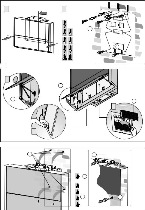
Carefully read the following important information regarding installation safety and maintenance. Keep this information booklet accessible for further consultations. The appliance has been designed for use in the ducting version (air exhaust to the outside – Fig.1B), filtering version (air circulation on the inside – Fig.1A) or with external motor (Fig.1C).
SAFETY PRECAUTION
1. Take care when the cooker hood is operating simultaneously with an open fireplace or burner that depend on the air in the environment and are supplied by other than electrical energy, as the cooker hood removes the air from the environment which a burner or fireplace need for combustion. The negative pressure in the environment must not exceed 4Pa (4x10⁻⁵ bar). Provide adequate ventilation in the environment for a safe operation of the cooker hood.
Follow the local laws applicable for external air evacuation.
Before connecting the model to the electricity network:
-Control the data plate (positioned inside the appliance) to ascertain that the voltage and power correspond to the network and the socket is suitable. If in doubt ask a qualified electrician.
-If the power supply cable is damaged, it must be replaced with another cable or a special assembly, which may be obtained direct from the manufacturer or from the Technical Assistance Centre.
-This device must be connected to the supply network through either a plug fused 3A or hardwired to a 2 phase spur protected by 3A fuse.
2. Warning!
In certain circumstances electrical appliances may be a danger hazard.
A)Do not check the status of the filters while the cooker hood is operating.
B)Do not touch bulbs or adjacent areas, during or straight after prolonged use of the lighting installation.
C)Flambè cooking is prohibited underneath the cooker hood.
D)Avoid free flame, as it is damaging for the filters and a fire hazard.
E)Constantly check food frying to avoid that the overheated oil may become a fire hazard.
F)Disconnect the electrical plug prior to any maintenance.
G)This appliance is not intended for use by young children or infirm persons without supervision.
H)Young children should be supervised to ensure they do not play with the appliance
I)There shall be adequate ventilation of the room when the rangehood is used at the same time as appliances burning gas or other fuels.
L)There is a risk of fire if cleaning is not carried out in accordance with the instructions.
This appliance conforms to the European Directive EC/2002/96, Waste Electrical and Electronic Equipment (WEEE). By making sure that this appliance is disposed of in a suitable manner, the user is helping to prevent potential damage to the environment or to public health.
The symbol on the product or on the accompanying
paperwork indicates that the appliance should not be
 treated as domestic waste, but should be delivered to a suitable electric and electronic appliance recycling collection point. Follow local guidelines when disposing of waste. For more information on the treatment, re-use and recycling of this product, please contact your local authority, domestic waste collection service or the shop where the appliance was purchased.
INSTALLATION INSTRUCTIONS
•Assemblyandelectricalconnectionsmustbecarriedout by specialised personnel.
•Wear protective gloves before proceeding with the installation.
•Electric Connection:
Note! Verify the data label placed inside the appliance:
-If the symbol 


 appears on the plate, it means that no earth connection must be made on the appliance, therefore follow the instructions concerning insulation class II.
-If the symbol 


 DOES NOT appear on the plate, follow the instructions concerning insulation class I.
Insulation class II
-The appliance has been manufactured as a class II, therefore no earth cable is necessary. The plug must be easily accessible after the installation of the appliance. If the appliance is equipped with power cord without plug, a suitably dimensioned omnipolar switch with 3 mm minimum opening between contacts must be fitted between the appliance and the electricity supply in compliance with the load and current regulations.
-The connection to the mains is carried out as follows: BROWN = L line
BLUE = N neutral.
Insulation class I
This is a class I, appliance and must therefore be connected to an effiecient earthing system.
-The appliance must be connected to the electricity supply as follows:
BROWN = L line BLUE = N neutral
YELLOW/GREEN = earth.
The neutral wire must be connected to the terminal with the N symbol while the YELLOW/GREEN, wire must be connected to the terminal by the earth symbol .
When connecting the appliance to the electricity supply, make sure that the mains socket has an earth connection. After fitting the ducted cooker hood, make sure that the electrical plug is in a position where it can be accessed easily. If the appliance is connected directly to the electricity supply, an omnipolar switch with a minimum contact opening of 3 mm must be placed in between the two; its size must be suitable for the load required and it must comply with current legislation.
• The minimum distance between the support surfaces of the cooking pots on the cooker top and the lowest part of the cooker hood must be at least 48 cm. If a connection tube composed of two parts is used, the upper part must be placed outside the lower part. Do not connect the cooker hood exhaust to the same conductor used to circulate hot air
- 8 -

or for evacuating fumes from other appliances generated by other than an electrical source. Before proceeding with the assembly operations, remove the anti-grease filter(s) (Fig.5B) so that the unit is easier to handle.
-In the case of assembly of the appliance in the suction version prepare the hole for evacuation of the air.
•We recommend the use of an air exhaust tube which has the same diameter as the air exhaust outlet hole. If a pipe with a smaller diameter is used, the efficiency of the product may be reduced and its operation may become noisier.
•ATTENTION!Remove screws“F”(Fig. 2) before plugging in the appliance. These screws fasten down the counterweight, required for opening the front panel, during transport of the appliance. The screws may be on one or both sides of the hood, depending on the version. A label, or possibly several, indicate the location of the screws (Fig.2A).
•There is a manual or electronic vent on the front of the appliance for increasing the extraction capacity.
- If the vent on the front of the appliance is manual, pull the
panel outwards (Fig.3A).
- If the vent on the front of the appliance is electronic, press button D for about four seconds (Fig.17).
• Wall mounting:
-Mark the lower part of the back of the hood on the wall, Fig.4A (taking into account the minimum distance from the hob).
-Position the fixing template on the wall, making sure that the line coincides with the line previously made on the wall.
-Mark the fixing holes and cut them into the material (Fig.4B).
-Fasten the 7 rawl bolts and the 2 screws C without tightening them fully (Fig.4B).
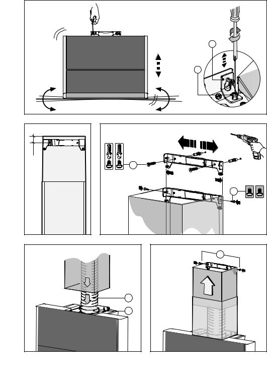
-Position the appliance at the wall (Fig.6).
-Make sure the 2 levelling screws J are tightened (Fig.7).
-Align the appliance horizontally using the two levelling screws J (Fig.7).
-When you have done the above, open panel K (Fig.5) and remove the anti-grease filter (Fig.5B). It is now possible to fasten the hood on definitively by tightening screws C and D (Fig.6).
-For easy accessibility to the motor unit in the case of assistance, after having levelled and fixed the appliance definitively, we recommend that the brackets are removed (Fig.7A).
-When carrying out the fixing operations, use only screws and screw anchors suited to the type of wall (e.g. reinforced concrete, plasterboard etc.).
-If the screws and screw anchors are supplied with the appliance, make sure that they are suited to the type of wall to which the hood must be fixed.
• Installation of models without decorative ducts:
Extractor hood
-Unclip the canopy M and remove the grille E (Fig.14A).
-Pass the power supply cable through the slot in the canopy M, as indicated in Fig.14B.
-Taking the grommet H, position it between the power cable and the slot.
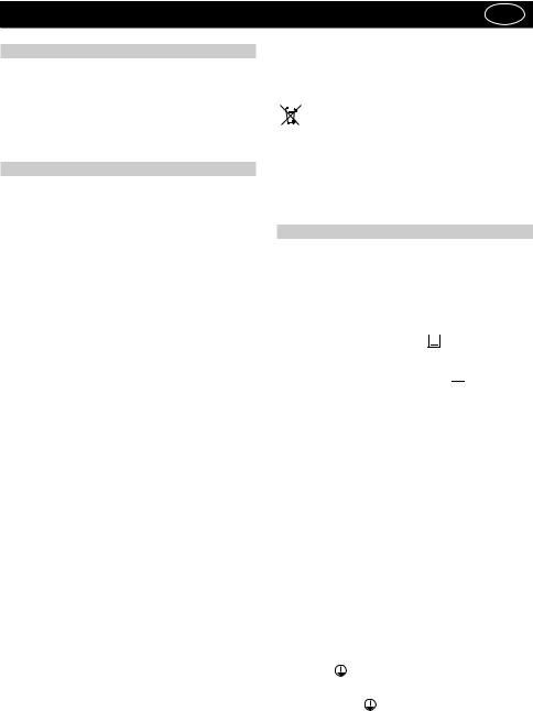
-Warning: the cooker hood may be installed with the air exhaust outlet at the rear, by removing bracket X with the motor and rotating it, as illustrated in Fig.12.
The wall mounting bracket Y should also be removed and fixed as illustrated in Fig.12, using the same screws.
-Connect the flexible hose L (not supplied) to the hood, so that it is aligned with the air exhaust outlet.
If the air exhaust is on top, use Fig.13A as a guide; otherwise, if it is at the rear, use Fig.13B as a guide.
-Fix the small cupola M and the grille E making sure that is it perfectly hooked on to the fastening pins G (Fig.13B).
-Filtering version:
-Unclip the canopy M and remove the grille E (Fig.14A).
-Pass the power supply cable through the slot in the canopy M, as indicated in Fig.14B.
-Taking the grommet H, position it between the power cable and the slot.
-To insert the active carbon filters iin the hood, undo the support G (Fig.5A). Open and lift panel K. Remove the anti-grease filter by pulling the handle as shown in Fig.5B. Hold the active carbon filters Z and fit them in as shown in Fig.5C.
-Fix the small cupola M and the grille E making sure that is it perfectly hooked on to the fastening pins G (Fig.13B).
• Installation of models with decorative ducts:
-Extractor hood
-The fairing M should be removed before installing decorative ducts (Fig.14A).
-Make sure the electrical power supply is within the measurements of the decorative connector.
-If your appliance is to be installed in the ducting version or in the version with external motor, prepare the air exhaust opening.
-Adjust the width of the support bracket of the top connector (Fig.9).
-Next, fasten it onto the wall making sure it is perfectly aligned with the hood, using the screws A (Fig.9). It must be at the correct distance from the ceiling, as shown in Fig.8.
-Connect flange F to the air exhaust hole using flexible hose L (Fig.10).
-Slide the top connector inside the lower duct and place this on the body (Fig.11).
-Pull out the top duct as far as the bracket and secure it using screws B (Fig.11).
-Filter version:
Attention!
-If you wish to turn your EXTRACTOR hood into a FILTER one, you need to contact your retailer to order either nonregenerative active carbon filters (Fig.5C) or regenerative active carbon filters (Fig.15).These are available as accessories.
• On request:
-The version with manual front vent can be equipped, on request, with an “ambient light”. This function is activated by pressing button “D” (Fig.17) for about 4 seconds. To turn off the light, simply press and hold the same button for about 4 seconds.
USE AND MAINTENANCE
•We recommend that the cooker hood is switched on before any food is cooked. We also recommend that the appliance is left running for 15 minutes after the food is cooked, in order to thoroughly eliminate all contaminated air.
The effective performance of the cooker hood depends on constant maintenance; the anti-grease filter and the active carbon filter both require special attention.
•The anti-grease filter is responsible retaining the grease
particles suspended in the air, therefore it is subject to clogging with variable frequency according to the use of the appliance.
- To prevent the danger of possible fires, at least every 2
- 9 -
months one must wash the anti-grease filters by hand using non-abrasive neutral liquid detergents or in the dishwasher at low temperatures and on short cycles.
- After a few washes, colour alterations may occur. This does not give the right to claim their replacement.
•The active carbon filters are used to purify the air that is sent back into the room and its function s to mitigate the unpleasant odours produced by cooking.
- The non-regenerable active carbon filters must be replaced at least every 4 months. The saturation of the active charcoal depends on the more or less prolonged use of the appliance, on the type of kitchen and on the frequency with which antigrease filter is cleaned.
- Regenerable active charcoal filters must be washed by hand, with non abrasive neutral detergents, or in the dishwasher at a maximum temperature of 65°C (the washing cycle must be complete without dishware). Remove excess water without damaging the filter, remove the plastic parts, and let the mat dry in the oven for at least 15 minutes approximately at a maximum temperature of 100°C. To keep the regenerable charcoal filter functioning efficient this operation must be repeated every 2 months. These must be replaced at least every 3 years or when the mat is damaged.
•Beforeremountingtheanti-greasefiltersandtheregen- erable active charcoal filters it is important that they are completely dry.
•Clean the hood frequently, both internally and externally, using a cloth dampened with denatured alcohol or neutral liquid detergents that are non abrasive.
•The lighting .system is designed for use during cooking and not for the prolonged general lighting of the room. The prolonged use of the lighting system significantly decreases the average duration of the bulbs.
•If the appliance is equipped with courtesy lights it is possible to use them for general room lighting for a prolonged amount of time.
•Attention: The non compliance with the hood cleaning
warnings and with the replacement and cleaning of the filters entails risk of fires. One therefore recommends keeping to the suggested instructions.
• Replacing halogen light bulbs (Fig.16.1):
To replace the halogen light bulbs B, remove the glass pane C using a lever action on the relevant cracks.
Replace the bulbs with new ones of the same type. Caution: Do not touch the light bulb with bare hands.
• Replacing LED lamps (Fig.16.2):
If the appliance version is with LED lamps, the intervention of a specialised technician is necessary to replace them.
• Commands (Fig.17):
NOTE: With this control it is possible to manage the appliance also with a remote control to be requested as accessory.
Power Button (A) = the on / off button switches on and off the whole hood (motor and lights).
By pressing the button the motor starts at 1st speed.
Fan Speed button (B) = From the OFF position, press once for the 1st speed, twice for the 2nd speed and three times for the 3rd speed. In order to activate the intensive speed, press the button for 5 seconds regardless of the status of the hood. For each speed only the led indicating the set speed will turn on. The intensive speed is indicated by the flashing of the led indicating speed 3. The duration of the intensive speed is 10 minutes; after this time the hood goes back to the last set speed.
In order to remove the intensive speed press the power button and the hood will switch off, or press the Fan speed button and the speed goes back to the previously set one. Speed of the hood with cyclic trend.
Light button (C)= There are three light levels: High, medium, low.
From the off position press once for the high level, twice for the medium level, three times for the low level and four times to turn the lights off.
The level of the lights has a cyclic trend: High, medium, low, off. Timer button (D) = With any type of speed (excluding the intensive speed), by pressing the button, the timer function is activated for 15 minutes. After this time has elapsed the hood will turn off (motor and any light on).
Lights indicator (E) =The lights indicator will switch on when the lights are on at any level.
Filters indicator (F) = After 30 minutes of operation, the led of the filters indicator will switch on, not flashing indicating that the anti-grease filters have to be washed.To reset the function (with the hood off), press the Fan speed button for 5 seconds. After this operation, the led of the filters indicator turns off and the setting of the 30 hours starts again from the beginning. After 120 hours the led will flash continuously. This means that the carbon filters have to be replaced (if present).To reset the function (with hood off) press the Fan speed button for 5 seconds. After this operation, the led of the indicator turns off and the setting starts again from the beginning.
Clean air indicator (G) = With the hood off, press the Power button (A) for 5 seconds to activate the clean air function.This will switch on the motor at speed 1 for 10 minutes every hour. The light indicator will switch on without flashing and the led of the 1st speed will switch on. In the remaining 50 minutes the light indicator will flash. The function can be deactivated by pressing any button except for the lights one.
THE MANUFACTURER DECLINES ALL RESPONSIBILITY FOR EVENTUAL DAMAGES CAUSED BY BREACHING THE ABOVE WARNINGS.
- 10 -
ČESKY |
|
|
CZ |
||
ÚVOD’ |
přispívá k předcházení případným negativním následkům na |
||||
|
životní prostředí a na zdraví. |
|
|
||
Přečtěte si pozorně obsah návodu, protože poskytuje dů- |
Symbol na výrobku nebo na přiložené dokumentaci |
||||
ležité informace týkající se bezpečné instalace, používání i |
|||||
poukazuje na to, že se s tímto výrobkem nesmí zacházet |
|||||
údržby zařízení. Uchovejte si návod pro jakoukoliv budou- |
|||||
jako s běžným domovním odpadem, ale musí se odeslat |
|||||
cí potřebu. Přístroj je určen k odsávání (odvádění vzduchu |
|||||
do vhodné sběrny určené pro recyklaci elektrických a |
|||||
ven – Obr.1B), filtrování (recyklace vzduchu v místnos- |
|||||
elektronických zařízení. Zařízení se musíte zbavit v souladu |
|||||
ti – Obr.1A) nebo k použití s externě umístěným motorem |
|||||
s místními předpisy pro likvidaci odpadu.Podrobnější infor- |
|||||
(Obr.1C). |
|||||
mace o zacházení s tímto výrobkem, jeho opětovným použi- |
|||||
|
|||||
BEZPECNOSTNÍ OPATRENÍ |
tím a recyklací můžete získat, když se obrátíte na příslušný |
||||
|
místní úřad, sběrnou službu domovního odpadu nebo ob- |
||||
1. Vyžaduje se opatrnost, jestliže jsou současně v činnosti |
chod, ve kterém jste výrobek zakoupili. |
|
|||
|
|
|
|
||
odsávač par a jiný hořák nebo tepelné zařízení závisející na |
NÁVOD K INSTALACI |
|
|
||
vzduchu místnosti a napájené jinou energií než elektrickou, |
|
|
|
|
|
protože odsávač par spotřebovává vzduch z okolí, který |
• Operace spojené s montáží a elektrická napojení musí |
||||
hořák nebo jiné tepelné zařízení potřebují ke spalování. Ne- |
|||||
být provedeny pouze odborným personálem. |
|||||
gativní tlak nesmí překročit 4Pa (4x10⁻⁵ bar). K bezpečnému |
|||||
• Používat ochranné rukavice pro provádění operací |
|||||
provozu je tedy nutná odpovídající ventilace místnosti. Při |
|||||
montáže. |
|
|
|
||
odvádění vzduchu do vnějšího prostředí je nutné se řídit |
|
|
|
||
|
|
|
|
||
platnými předpisy Vaší země. |
• Elektrické zapojení: |
|
|
||
|
|
|
|||
Před napojením modelu na elektrickou síť: |
Poznámka! Zkontrolujte štítek umístěný uvnitř zařízení: |
||||
-Když se na štítku nachází symbol |
, znamená to, že zaří- |
||||
Zkontrolujte tabulku s údaji umístěnou uvnitř přístroje a |
|||||
zení nesmí být uzemněno, postupujte tudíž podle pokynů |
|||||
ověřte si, že napětí a výkon odpovídají místní síti a rovněž |
|||||
týkajících se třídy izolace II. |
|
|
|||
zásuvka je vhodná. V případě jakékoliv pochyby se poraďte |
|
|
|||
-Když na štítku NENÍ uveden symbol |
, postupujte dle |
||||
s kvalifikovaným elektrikářem. |
|||||
pokynů týkajících se třídy izolace I. |
|
|
|||
- Je-li napájecí kabel poškozen, musí být nahrazen speciál- |
|
|
|||
|
|
|
|
||
ním kabelem nebo sadou, které jsou k dispozici u výrobce |
Třída izolace II |
|
|
|
|
nebo v jeho servisním středisku. |
|
|
|
||
Zařízení je vyrobeno v II. třídě, a proto žádný vodič nesmí |
|||||
- Připojte zařízení k napájení prostřednictvím zástrčky s po- |
|||||
být uzemněn. |
|
|
|
||
jistkou 3A nebo ke dvěma vodičům dvou fází, chráněným |
|
|
|
||
Po instalaci zařízení musí být zástrčka snadno přístupná. |
|||||
pojistkou 3A. |
|||||
V případě, že je zařízení vybaveno kabelem bez zástrčky, je |
|||||
|
|||||
2. Upozornění! |
pro jeho připojení do elektrického rozvodu třeba mezi zaří- |
||||
zení a elektrický rozvod zapojit omnipolární stykač s mini- |
|||||
V některých situacích mohou být elektrická zařízení |
|||||
mální vzdáleností kontaktů 3 mm, navržený pro příslušnou |
|||||
zdrojem nebezpečí. |
|||||
zátěž a odpovídající platným normám. |
|
|
|||
A) Nekontrolujte stav filtrů, zatímco je odsavač v činnos- |
|
|
|||
Napojení k elektrické síti musí být provedeno následovně: |
|||||
ti. |
|||||
HNĚDÁ = L vodič |
|
|
|
||
B) Nedotýkejte se žárovek a přilehlých prostor během |
|
|
|
||
MODRÁ = N neutrální vodič. |
|
|
|||
dlouhodobého použití osvětlení nebo bezprostředně po |
|
|
|||
|
|
|
|
||
něm. |
Třída izolace I |
|
|
|
|
C) Je zakázáno připravovat jídla na plameni pod odsa- |
|
|
|
||
Toto zařízení je vyrobeno ve třídě I, a proto musí být připojeno |
|||||
vačem. |
|||||
k uzemnění. |
|
|
|
||
D) Vyhněte se použití volných plamenů, protože poško- |
|
|
|
||
Připojení k elektrické síti musí být provedeno následovně: |
|||||
zují filtry a mohou způsobit požár. |
|||||
HNĚDÝ = L fázový vodič |
|
|
|||
E) Udržujte neustále pod kontrolou smažení jídel, aby se |
|
|
|||
MODRÝ = N nulový vodič |
|
|
|||
zabránilo vznícení rozpáleného oleje. |
|
|
|||
ŽLUTO/ZELENÝ = |
zemnicí vodič. |
|
|
||
F) Před zahájením údržby odpojte zástrčku ze zásuvky |
|
|
|||
Nulový vodič musí být připojen ke svorce označené symbolem |
|||||
elektrického rozvodu. |
|||||
N, zatímco ŽLUTO/ZELENÝ vodič musí být připojen ke svorce |
|||||
G) Zařízení není určeno pro použití dětmi nebo nesvé- |
|||||
nacházející se v blízkosti symbolu uzemnění . |
|||||
právnými osobami bez dozoru. |
|||||
Během operace elektrického zapojení se ujistěte, zda je |
|||||
H) Dohlížejte na děti, abyste si byli jisti, že si nehrají se |
|||||
elektrická zásuvka vybavena uzemněním. Po uskutečnění |
|||||
zařízením. |
|||||
montáže odsavače dávejte pozor, aby byla poloha zástrčky |
|||||
I) Když je odsavač používán současně se zařízeními spa- |
|||||
elektrického přívodu snadno dostupná. V případě přímého |
|||||
lujícími plyn nebo jiná paliva, místnost se musí vhodně |
|||||
zapojení k elektrické síti je třeba mezi zařízení a elektrickou |
|||||
větrat. |
|||||
síť zapojit omnipolární stykač s minimální vzdáleností kon- |
|||||
L) Když nebudou řádně provedeny úkony údržby, existu- |
|||||
taktů 3 mm, navržený pro příslušnou zátěž a odpovídající |
|||||
je riziko vzniku požáru. |
|||||
platným normám. |
|
|
|
||
|
|
|
|
||
Toto zařízení je označeno v souladu s Evropskou směrnicí 2002/96/ES,Waste Electrical and Electronic Equipment (WEEE). Tím, že se uživatel ujistí o správné likvidaci tohoto výrobku,
• Minimální vzdálenost mezi opěrnou plochou varných nádob na varném zažízení a nejnižším bodem kuchyňského krytu musí být alespoň 48 cm. Vývod odsavače nesmí být napojen
- 11 -

na vývod, ve kterém cirkuluje teplý vzduch, nebo který je používán k odvádění kouře ze zařízení napájených jinou energií než elektrickou. Před zahájením montáže vyjměte z odsavače tukový filtr (Obr.5B). Usnadníte si tak manipulaci s přístrojem. - V případě montáže přístroje ve verzi odsávače je třeba připravit otvor k evakuaci vzduchu.
•Doporučuje se použít trubku pro odvádění vzduchu se stejným průměrem jako hrdlo výstupu vzduchu. Použití redukce by mohlo negativně ovlivnit vlastnosti výrobku a zvýšit hlučnost.
•POZOR! Před připojením přístroje k elektrické síti odstraňte šrouby “F” (Obr.2). Ty slouží k zablokování protizávaží, nezbytného pro otevření předního panelu, během přepravy přístroje. V závislosti od modelu, který vlastníte, mohou být šrouby na jedné straně nebo na obou stranách odsavače par. Šrouby jsou označeny jedním nebo více štítky (Obr.2A).
•Pro lepší sací schopnost je přístroj vybaven předním otvíráním , manuálním nebo elektronickým.
- Je-li přístroj vybaven předním manuálním otvíráním,
potáhněte dvířka směrem ven (Obr.3A).
- Je-li přístroj vybaven předním elektronickým otvíráním, stiskněte tlačítko D po dobu asi 4 vteřiny (Obr.18).
• Montáž na stěnu
-Narýsujte spodní stranu zadní části odsavače na zeď Obr.4A (s ohledem na minimální vzdálenost od varné desky).
-Umístěte upevňovací šablonu na zeď, ujistěte se, že linie se překrývá s linií předtím vyznačenou na zdi.
-Vyznačte a vyvrtejte upevňovací díry (Obr.4B).
-Upevněte 7 kotvících hmoždinek a 2 šrouby C bez úplného dotažení (Obr.4B).
-Umístěte přístroj na zeď (Obr.6).
-Ujistěte se, že 2 stavěcí šrouby J jsou utažené (Obr.7).
-Vyrovnejte přístroj do vodorovné polohy pomocí dvou stavěcích šroubů J (Obr.7).
-Po nastavení otevřete panel K (Obr.5) a vyjměte protitukový filtr (Obr.5B), pak bude možné definitivně upevnit odsavač pomocí šroubů C a D (Obr.6).
-Pro snadnější přístup k motoru v případě servisního zásahu doporučujeme po vyrovnání a definitivním upevnění přístroje odstranit podpěry (Obr.7a).
-Pro různé montážní podmínky použijte příslušné typy šroubů a hmoždinek, které budou odpovídat typu zdiva (např. armovaný beton, sádrokarton atd.).
-Budou-li šrouby a hmoždinky dodány jako součást produktu, ujistěte se, zda odpovídají typu zdiva, na něž má být odsavač namontován.
• Instalace pro modely bez estetických komínů
-Odsávací verze
-Odepněte vrchlík M a sejměte mřížku E (obr. 14A).
-Provlečte napájecí kabel podélným otvorem vrchlíku M, naznačeným na obr. 14B.
-Uchopte kabelovou průchodku a umístěte ji mezi napájecí kabel a podélný otvor.
-Upozornění: Odsavač lze namontovat také s výstupem vzduchu v zadní části, po demontáži třmene X s motorem a jeho otočení podle nákresu na obr. 12.
Odmontujte také třmen pro upevnění na stěnu Y a umístěte jej způsobem znázorněným na obr. 12 s použitím stejným šroubů.
-Připojte hadici L (není součástí zařízení) k odsavači v závislosti na zvolené poloze otvoru pro výstup vzduchu.
Ohledně horního výstupu vzduchu vycházejte z obr. 13A, zatímco ohledně zadního výstupu vzduchu vycházejte z ob- r.13B.
-Umístěte vrchlík M a mřížku E, dávejte přitom pozor, aby se perfektně nasadili na fixující čepy G (Obr.13B).
-Filtrační verze
-Odepněte vrchlík M a sejměte mřížku E (obr. 14A).
-Provlečte napájecí kabel podélným otvorem vrchlíku M, naznačeným na obr. 14B.
-Uchopte kabelovou průchodku a umístěte ji mezi napájecí kabel a podélný otvor.
-Pro vložení filtrů s aktivním uhlíkem do odsavače uvolněte podpěrný suport G (Obr.5A). Otevřete a zvedněte panel K. Vyjměte protitukový filtr zatažením za kliku, jak je znázorněno na Obr.5B. Vemte filtry s aktivním uhlím Z a umístěte je, jak je znázorněno na Obr.5C.
-Umístěte vrchlík M a mřížku E , dávejte přitom pozor, aby se perfektně nasadili na fixující čepy G (Obr.13B).
• Instalace pro modely s estetickými komíny
-Odsávací verze
-Před instalací estetických komínů je třeba provést demontáž vrchlíků M (obr. 14A).
-Přiveďte elektrické napájení do prostoru dekorativního komínu.
-Má-li být váš přístroj nainstalován ve verzi odsávání nebo v provedení s externě umístěným motorem, proveďte otvor pro odtah vzduchu.
-Seřiďte šířku opěrného třmene horního estetického komínu (Obr. 9).
-Následně jej připevněte na zeď pomocí šroubů tak, aby byl v osi s vaším odsavačem A (Obr.9) a dodržujte vzdálenost od stropu znázorněnou na Obr.8.
-Prostřednictvím hadice L připojte přírubu F k otvoru pro odvádění vzduchu (Obr. 10).
-Zasuňte horní estetický komín dovnitř spodního estetického komínu a opřete jej o rám (Obr. 11).
-Vyvlečte horní estetický komín až po třmen a upevněte jej prostřednictvím šroubů B (Obr. 11).
-Filtrační verze:
Pozor!
-Pro proměnu odsavače z verze ODSÁVACÍna verzi FILTRAČNÍ se musí neregenerovatelné filtry s aktivním uhlíkem (Obr.5C) nebo regenerovatelné filtry s aktivním uhlíkem (Obr.15) objednávat u vašeho prodejce jako příslušenství přístroje.
• Volitelný prvek:
-Pro verzi s manuálním předním otvíráním je možné požádat o “osvětlení prostředí”. Je možné aktivovat tuto funkci stiskem tlačítka “D” (Obr.18) po dobu asi 4 vteřiny. Pro deaktivaci osvětlení stiskněte opětovně stejné tlačítko po dobu asi 4 vteřiny.
POUŽITÍ A ÚDRŽBA
•Doporučujeme uvést zařízení do činnosti ještě před zahájením přípravy jakéhokoli jídla. Doporučujeme ponechat zařízení v činnosti i po dobu 15 minut po ukončení přípravy jídel, aby byl kompletně odveden zapáchající vzduch. Správná činnost odsavače je podmíněna správnou a nepřetržitou údržbou; zvláštní pozornost je třeba věnovat protitukovému filtru a filtru s aktivním uhlím.
•Protitukový filtr má za úkol zachycovat mastné částice
nacházející se ve vzduchu, proto je v průběhu proměnné doby vystaven ucpávání; tato doba závisí na používání zařízení.
- 12 -
-Abyste předešli případnému nebezpečí požáru, je nutné nejméně jednou za dva měsíce nutné propláchnout filtry proti mastnotě v ruce pomocí neutrálních neabrazivních čisticích prostředků nebo v myčce na nádobí při nízkých teplotách v krátkém mycím programu.
-Po několika mytích může dojít ke změně barvy. Tento jev neopravňuje k reklamaci pro eventuální výměnu.
• Filtry s aktivním uhlíkem slouží pro pročištění vzduchu,
který se vypouští do prostředí a pohlcují nepříjemné zápachy, které vznikají během vaření.
-Aktivní uhlíkové filtry, které nelze regenerovat, je zapotřebí měnit každé 4 měsíce. Saturace aktivního uhlíku závisí více- -méně od délky používání přístroje, typu kuchyně a pravidelnosti, se kterou se provádí čištění filtru proti mastnotě.
-Aktivní uhlíkové filtry, které lze regenerovat, je možné mýt v rukou pomocí čistících neutrálních a neabrazivních prostředků, anebo je možné je mýt v myčce na nádobí s maximální teplotou 65°C (cyklus mytí se musí provádět bez nádobí). Odstraňte přebytek vody bez toho, že byste poškodili filtr, odstraňte části z plastů a nechte vysušit podložku v rouře po dobu přibližně 15 minut o teplotě maximálně 100°C. Pro udržování funkčnosti uhlíkového filtru s možností regenerace je zapotřebí zopakovat tuto operaci každé 2 měsíce. Tyto filtry se musí vyměnit jednou za 3 roky anebo když je podložka poškozena.
• Před opětovným namontováním filtru proti mastnotě a aktivních uhlíkových filtrů, které lze regenerovat, je důležité, aby byli pořádně suché.
• Opakovaně čistěte odsavač, zevnitř i zvenčí, s použitím hadru navlhčeného v denaturovaném lihu nebo neabrazivních tekutých čisticích prostředcích.
•Osvětlení je navrženo pro použití během vaření a ne pro dlouhodobější použití za účelem osvětlení okolního prostředí. Dlouhodobější použití osvětlení výrazně snižuje průměrnou životnost žárovek.
•Pokud je přístroj vybaven osvětlením prostředí, toto může být používáno pro všeobecné dlouhodobé osvětlování daného prostředí.
•Pozor: nedodržování pokynů k čištění odsavače a výměny a čištění filtrů zapříčinit rizika požáru. Doporučuje se proto dodržovat tyto pokyny.
•Výměna halogenových žárovek (Obr.16.1):
Při výměně halogenových žárovek B sejměte sklíčko C po jeho nadzvednutí v místě příslušných otvorů.
Žárovky nahraďte novými žárovkami stejného druhu. Upozornění: nedotýkejte se žárovky holýma rukama.
• Výměna žárovek LED (Obr.16.2):
Je-li verze výrobku vybavena žárovkami LED pro jejich výměnu je potřebný zásah specializovaného technika.
• Ovládání (Obr.17):
POZNÁMKA: tímto ovládáním je možné kontrolovat přístroj i pomocí dálkového ovládání, které si můžete zakoupit jako příslušenství.
Tlačítko Power (A) = Zapínací/vypínací tlačítko zapne a vypne celý odsavač (motor a světla).
Aktivací tohoto tlačítka se spustí 1. rychlostní stupeň motoru. Tlačítko Fan speed (B) = Z polohy OFF ho stiskněte jednou pro 1. rychlostní stupeň, dvakrát pro 2. rychlostní stupeň a třikrát pro 3. rychlostní stupeň. Pro zařazení intenzivní rychlosti stiskněte a držte stisknuté tlačítko 5 sekund nezávisle na stavu, ve kterém se odsavač nachází. U každého rychlostního stupně se rozsvítí pouze kontrolka LED signalizující nastavenou rychlost. Intenzivní rychlost je signalizována kontrolou LED 3. rychlostního stupně, která bliká. Intenzivní rychlost trvá 10
minut. Poté se odsavač vrátí k poslední nastavené rychlosti. Pro vypnutí intenzivní rychlosti stiskněte tlačítko Power a odsavač se vypne, nebo stiskněte tlačítko Fan speed a dojde k obnovení rychlosti nastavené v předchozí fázi.
Tlačítko light (C) = Stupně osvětlení jsou tři: vysoký, střední a nízký.
Z polohy OFF zatlačte jednou pro aktivaci vysokého stupně, dvakrát pro aktivaci středního stupně, třikrát pro aktivaci nízkého stupně a čtyřikrát pro vypnutí světel.
Stupeň osvětlení funguje v cyklickém pořadí: vysoký, střední, nízký, vypnuto.
POZOR! Tato funkce je k dispozici pouze pro halogenové žárovky, NIKOLIV pro žárovky LED.
Tlačítko timer (D) = Jestliže stisknete toto tlačítko s jakoukoliv zařazenou rychlostí (kromě intenzivní rychlosti), aktivuje se funkce Timer (na 15 minut). Po uplynutí této doby se odsavač vypne (motor a případně zapnutá světla).
Jestliže je výrobek opatřen zvláštním příslušenstvím jako zdvořilostní nebo boční osvětlení, pro jejich zapnutí stačí stisknout a držet stisknuté tlačítko Timer po dobu 4 sekund. Pro jejich vypnutí proveďte stejnou operaci.
Kontrolka osvětlení (E) = Kontrolka osvětlení se rozsvítí v případě rozsvícení osvětlení (jakýkoliv stupeň).
Kontrola filtrů (F) = Po 30 hodinách provozu se rozsvítí LED kontrolky filtrů, což značí, že je nutné vyčistit protitukové filtry. Funkce se resetuje (s vypnutým odsavačem) stisknutím tlačítka Fan speed na 5 sekund. Po provedení této operace se signalizační LED filtrů vypne a nastavení 30 h se spustí znovu od nuly. Po 120 hodinách začne kontrolka LED blikat nepřetržitě. To znamená, že je nutné vyměnit uhlíkové filtry (jsou-li namontovány). Funkce se resetuje (s vypnutým odsavačem) stisknutím tlačítka Fan speed na 5 sekund. Po provedení této operace se signalizační LED vypne a nastavení se spustí znovu od nuly.
Kontrolka čistého vzduchu (G) = Jestliže stisknete (s vypnutým odsavačem) na 5 sekund tlačítko Power (A), aktivuje se funkce Clean air. Tato funkce zapne motor (1. rychlostní stupeň) na 10 minut (každou hodinu). Rozsvítí se kontrolka a zůstane svítit a dále se rozsvítí LED kontrolka 1. rychlostního stupně. Během dalších 50 minut bude kontrolka blikat. Funkce se vypne stisknutím jakéhokoliv tlačítka s výjimkou světel.
VÝROBCE ODMÍTÁ JAKOUKOLIV ZODPOVĚDNOST ZA ŠKODY ZPŮSOBENÉ NEDODRŽENÍM UVEDENÝCH UPOZORNĚNÍ.
- 13 -
DANSK |
DK |
GENERELLE OPLYSNINGER
Læs omhyggeligt indholdet af denne brugsanvisning, da den giver vigtige oplysninger vedrørende sikkerheden ved installering, brug og vedligeholdelse. Opbevar brugsanvisningen til senere brug. Apparatet er udarbejdet til at kunne fungere; udsugende (udledning af luft til eksterne omgivelser Fig.1B) filtrerende (intern cirkulation af luft Fig.1A) og med udvendig motor. (Fig.1C).
OPLYSNINGER VEDRØRENDE SIKKERHED
1. Udvis forsigtighed hvis der samtidigt med emhætten er en varmekilde eller flamme i funktion, som er afhængig af luften i omgivelserne og forsynet med energi, der ikke er elektrisk, eftersom emhætten fjerner den luft fra omgivelserne, som flammen eller varmekilden har brug for til forbrænding. Det negative tryk i lokalet må ikke overstige 4 Pa (4x10 -5 bar). For størst mulig sikkerhed, sørg for en passende ventilation af rummet. Hvad angår udsugningen til eksterne omgivelser følg de gældende normer.
Før modellen tilsluttes el-nettet:
-Kontrollèr informationsetiketten (placeret indeni apparatet), for at sikre, at spændingen og styrken er i overensstemmelse med el-nettet og at stikkontakterne er egnede. Hvis De er i tvivl, konsultèr en kvalificeret elektriker.
-Hvis forsyningsledningen er beskadiget, skal den udskiftes med en ledning eller en særlig samling fra fabrikanten eller et autoriseret servicecenter.
-Tilslut forsyningsenheden ved hjælp af et stik med en 3A sikring eller til de to tofaseledninger, som er beskyttet af en 3A sikring.
2. Pas på!
I nogle situationer kan elektriske apparater udgøre en fare.
A)Undgå at kontrollere filtrenes tilstand mens emhætten er i funktion.
B)Rør ikke ved pærer eller tilstødende områder under eller lige efter længerevarende brug af belysningsanlægget.
C)Det er ikke tilladt at tilberede madvarer for åben ild under emhætten.
D)Undgå åben ild, da det kan beskadige filtrene og medføre fare for brand.
E)Hold altid øje med maden under friturestegning for at undgå, at olien antændes.
F)Træk stikket ud af stikkontakten, inden der foretages vedligeholdelse.
G)Apparatet må ikke bruges af børn eller af personer, der ikke har de mentale eller fysiske egenskaber til korrekt brug, uden overvågning.
H)Hold øje med børnene for at sikre, at de ikke leger med apparatet.
I)Når emhætten anvendes samtidigt med apparater, der bruger gas eller andre brændstoffer, skal rummet have tilstrækkelig udluftning.
L)Hvis rengøring ikke udføres i overensstemmelse med anvisningerne, kan det medføre brandfare.
Dette apparat er udviklet i overensstemmelse med det europæiske direktiv 2002/96/EF om affald af elektrisk og
elektronisk udstyr (WEEE). Ved at sikre sig, at dette produkt bortskaffes på korrekt vis, bidrager brugeren til at forhindre eventuelle negative miljømæssige og sundhedsmæssige påvirkninger.
 Symbolet på produktet eller på dokumentationen, der følger med produktet, angiver, at produktet ikke skal
  behandles som husholdningsaffald, men at det skal bortskaffes på passende vis på genbrugsstationer til
elektriske og elektroniske apparater. Apparatet skal bortskaffes i overensstemmelse med de gældende regler for bortskaffelse af affald. For yderligere oplysninger om håndtering, genvinding og genbrug af dette produkt, bedes man kontakte de lokale myndigheder, teknisk forvaltning eller forretningen, hvor produktet er købt.
INSTRUKTION VED INSTALLERING
•Monteringenogudførelsenafdeelektriskeforbindelser, skal udføres af specialiseret personale.
•Inden man går frem med monteringen, skal man iføre sig beskyttelseshandsker.
•Den elektriske forbindelse:
Bemærk! Kontroller typeskiltet inden i apparatet.
-Hvis der på skiltet findes symbolet  , betyder det, at apparatet ikke skal jordes. Følg anvisningerne for isoleringsklasse II.
-Hvis der på skiltet IKKE vises symbolet  , skal man følge anvisningerne for isoleringsklasse I.
Isoleringsklasse II
Apparatet er udarbejdet i klasse II, derfor skal der ikke tilsluttes et kabel til jordforbindelsen.
Man skal nemt kunne nå ind til stikket efter installation af apparatet.
Hvis apparatet er udstyret med ledning uden stik, skal man ved tilkobling til strømforsyningen sørge for, at der mellem apparatet og strømforsyningen er installeret en flerpolet afbryder med en åbning på minimum 3 mm mellem kontakterne, som passer til belastningen og overholder de gældende regler.
Tilslutning til el-nettet skal udføres som følgende: BRUN = L Linje
BLÅ = N Neutal.
Isoleringsklasse I
Dette apparat er konstrueret i klasse I og skal derfor tilsluttes til et stik med jordforbindelse.
Tilslutningen til strømforsyningen skal udføres på følgende måde:
BRUN = L Linje
BLÅ = N Neutal GUL/GRØN = jord.
Den neutrale ledning skal tilsluttes til klemrækken med symbolet N mens den GUL/GRØNNE skal tilsluttes til klemrækken ud for jordsymbolet .
Når den elektriske tilslutning udføres, skal man sikre sig, at strømstikket har jordforbindelse. Efter montering af emhætten skal man sikre sig, at stikkontakten nemt kan nås. Ved direkte tilslutning til strømforsyningen skal der mellem apparatet og strømforsyningsnettet monteres en flerpolet afbryder med en minimumsafstand mellem kontakterne på 3 mm, der kan klare belastningen og overholder de gældende regler.
- 14 -
 Loading...