

Page 1
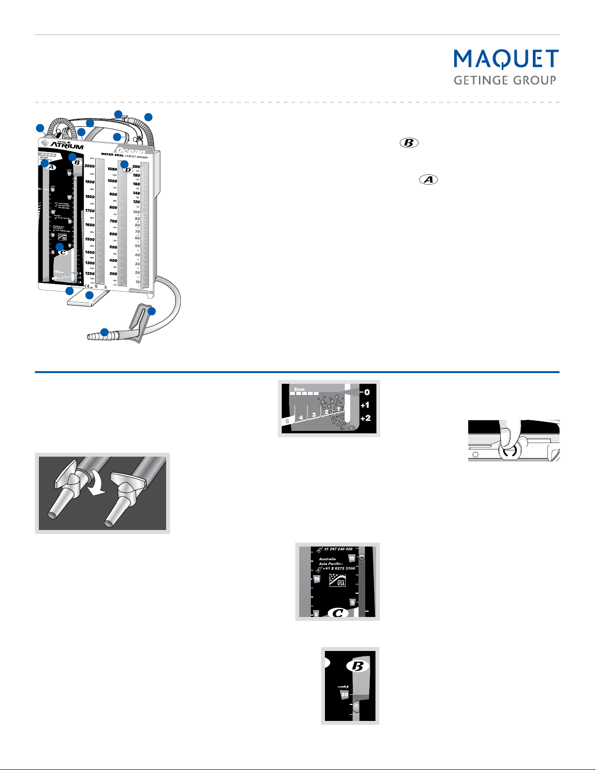
Atrium OCEAN
Water Seal Chest Drain
I
F
A
C
E
G
B
K
H
L
N
J
A Suction Control Chamber
B Water Seal Chamber
D
C Air Leak Monitor
D Collection Chamber
E Easy-to-Grip Handle
F Positive Pressure Release Valve
G Manual High Negativity Vent
H Multi-position Hangers
I In-line Connector
J Needleless Access Port
K Patient Pressure Float Ball
L Swing Out Floor Stand
M Patient Tube Clamp
N Patient Connector
M
What to check during system operation
• Suction control stopcock
The suction control stopcock regulates vacuum to the
chest drain. It provides effective control of suction control
bubbling and allows efficient use with any unregulated
suction source. The stopcock must be ON for initial system
set up and should not be turned OFF during patient use.
During patient transport or when suction is not
operating, it is not recommended to turn the stopcock
off or to clamp off suction tube.
ON
• Verifying system operation
Water seal and suction control chambers must be filled
and maintained to prescribed levels to ensure proper
operation and should be checked regularly when used for
extended periods. Water seal should be maintained at 2
cm line and suction control chamber should bubble gently
when connected to suction. Adjust stopcock or suction
source as needed to increase or decrease suction control
bubbling. As required, additional water may be added by
a 19 gauge or smaller needle and syringe via the grommet
located on the back.
• Placement of unit
Always place chest drain below the patient’s chest in an
upright position. To avoid accidental knock-over, open
the floor stand for secure placement on floor or hang the
system bedside with the hangers provided.
• Recording drainage volume
The collection chamber incorporates a writing surface with
easy-to-read fluid level graduations. Please refer to individual product inserts for specific model graduations.
• Observing water seal for patient air leaks
When air bubbles are observed going from right to left in
the air leak monitor, this will confirm a patient air leak.
OFF
Continuous
bubbling in the
water seal air leak
monitor will confirm a
persistent air leak.
Intermittent
bubbling with float
ball oscillation will
confirm the presence of an intermittent air leak.
No bubbling with minimal float ball oscillation at bottom of
water seal will indicate no air leak is present.
• Graduated air leak monitor
For those models with a graduated air leak monitor, air leak
bubbling can range from 1 (low) to 5 (high). Air bubbles
create an easy to follow air leak pattern for monitoring
patient air leak trends.
• Observing graduated water seal column for changes
in patient pressure
Patient pressure can be determined by observing the
level of the blue water
and small float ball in the
graduated water seal
column. With suction
operating, patient
pressure will equal the
suction control setting
plus the graduated water
seal column level only.
For gravity drainage (no
suction) patient pressure will equal the graduated water seal
column level only.
• High negativity float valve
The high negativity float valve,
with its controlled release action,
enables the thoracic patient to draw
as much intrathoracic pressure as
is required during each respiratory
cycle. During prolonged episodes
of extreme negative pressure, the
controlled release system will automatically relieve excess vacuum to
a lower pressure level.
• Set up
Step 1. Fill water seal to 2 cm line
Hold funnel down and fill to the top. Raise funnel to
empty water into water seal to 2 cm line.
Step 2. Fill suction control to desired pressure level(A)
Remove the tethered vent plug, pour water, and
replace vent plug.
Step 3. Connect chest drain to patient
Connect chest drain to patient prior to initiating suction.
Step 4. Connect chest drain to suction
To apply suction, connect suction source line directly
to the suction control stopcock or suction connector
provided. Adjust the suction control stopcock or
suction control source as needed to increase or
decrease suction control bubbling.
Have a question or need help in a hurry?
Call Maquet toll free at 1-800-528-7486.
• Manual high negativity vent
To lower the height of the water seal column or to lower
patient pressure when connected to suction, depress the
manual vent located on top of the drain until the float valve
releases and the water column returns to the desired level.
Do not use manual
vent to lower water
seal column when suction is not operating or
when the patient is on
gravity drainage.
• To prescribe suction pressure greater than -20 cmH
Suction pressure greater than -20 cmH2O can be imposed
directly by a graduated wall regulator or portable pump
by taping over the vent-plug with non-porous tape and
reading vacuum pressure directly from regulator or pump.
Vacuum pressures greater than -40 mmHg are not
recommended.
• Sampling patient drainage
Sampling of patient drainage must be in accordance with
approved hospital infection control standards. Selected
models include a needleless Luer port on the patient tube
connector for sampling patient drainage. Alcohol swab the
Luer port prior to syringe attachment (no needle). Fluid
samples can also be taken directly from the patient tube
by forming a temporary dependent loop and inserting a
19 gauge needle at an oblique angle. Alcohol swab the
patient tube prior to inserting syringe at a shallow angle.
Do not puncture patient tube with an 18 gauge or larger
needle.
• Positive pressure protection
The positive pressure release valve, located on top of
drain, opens to release accumulated positive pressure. Do
not obstruct the positive pressure release valve.
• System disconnection
For models equipped with an in-line connector, close
patient tube clamp prior to dis connecting chest drain
patient tube from patient. Clamp off all indwelling thoracic
catheters prior to disconnecting chest drain from patient.
• System disposal
Disposal of chest drain and its contents should be in
accordance with all applicable regulations.
Do not vent when suction Is not operating
0
2
Page 2

Troubleshooting
What happens when:
•There is no bubbling in the suction
control chamber?
Check to be sure the suction tubing is connected to the chest drain and to the wall
regulator and the suction source is turned
on. Adjusting the suction control stopcock is
required for constant gentle bubbling.
• There is vigorous bubbling in the suction
control chamber?
Vigorous bubbling causes quicker evaporation and produces excessive noise. Constant,
gentle bubbling is all that is required to impose
the prescribed amount of suction. The suction control stopcock, located on the suction
tubing, can be used to adjust bubbling. The
suction source regulator can also be adjusted
to turn suction control bubbling up or down.
Should the suction control stopcock be
turned off for gravity drainage or for patient
transport?
No. The patient is protected two ways; first
by the one-way valve created by the water
seal to maintain the desired patient vacuum
pressure, and second, the patient is protected
by the integral positive pressure valve in the
event the stopcock is turned off. It is not
necessary to turn off the stopcock, clamp, or
cap the suction line during gravity drainage or
patient transport. Both the water seal and the
positive pressure valve provide patient protection when either the suction line or stopcock
remain open or closed.
How can I connect multiple chest drains to
one suction source easily?
With models equipped with a suction control
stopcock, connection of two or more chest
drains to a common suction source is made
easier. Place a 1/4” x 1/4” x 1/4” Y connector
on the wall suction tubing.
Cut chest drain
suction line and
Illustration 1.
insert stopcock
into open tubing
Now you have two open ends of suction line
tubing for the Y connector to be placed. Turn
on suction and adjust the suction control
stopcock on each drain to achieve constant,
gentle bubbling with each.
Illustration 2.
Insert
Insert “Y”
How do I confirm my patient has an air leak
when there is:
•No bubbling in the water seal?
If there are no air bubbles observed going
from right to left in the air leak monitor, there
is no patient air leak. In order to confirm that
your patient’s chest catheter(s) are patent,
temporarily turn suction off and check for
oscillation of the patient pressure float ball in
the water seal column coinciding with patient
respiration.
•Bubbling present in the water seal?
Whenever constant or intermittent bubbling is
present in the water seal air leak monitor, this
will confirm an air leak is present. Oscillation
of the patient pressure float ball at the bottom
of the water seal without bubbling will indi-
cate no apparent air leak. Bubbling from right
to left must be present to confirm an air leak.
To determine the source of the air leak (patient
or catheter connection), momentarily clamp
the patient tube close to the chest drain and
observe the water seal. If bubbling stops, the
air leak may be from the catheter connections
or the patient’s chest. Check the catheter
connectors and patient dressing for a partially
withdrawn catheter. If bubbling continues after
temporarily clamping the patient tube, this will
indicate a system air leak requiring system
replacement.
If the chest drainage system has been
knocked over, can I use it and what should
I do?
After a chest drainage system has been knocked over, set it upright and immediately
check the fluid levels of the water seal and
suction control chambers for proper volumes.
We provide convenient dia phragms for access
with a 20 gauge or smaller needle and syringe
to adjust the water level in each chamber, if
required. Alcohol swab the needle access area
and aspirate any overfill that may have occurred. If the water seal has an inadequate fluid
level, simply replace the lost volume. If a significant amount of blood has entered the water
seal, it may be advisable to change the system
for a new one.
How do I lower the water seal column?
Changes in your patient’s pressure will be
reflected by the height of the water in the
water seal column. These changes are usually
due to mechanical means such as milking or
stripping patient drainage tubes, or simply by
deep inspiration by your patient after all air
leaks have subsided. If desired, the height of
the water column and patient pressure can be
reduced by temporarily depressing the filtered
manual vent, located on top of the drain, until
the float valve releases and the water column
lowers to the desired level. Do not lower water
seal column when suction is not operating or
when patient is on gravity drainage.
Is it normal for the patient pressure float
ball to fluctuate up and down (tidal) near the
bottom of the water seal column?
Yes. Once your patient’s air leak is resolved,
you will generally observe moderate tidaling in
the water seal column. Increases in intrathoracic pressure will cause the water level to rise
(the ball rises) during patient inspiration and
will lower or decrease (the ball drops) during
expiration. This diagnostic tool will help to
confirm patency of your patient’s catheter(s).
Minor “bouncing” of the water seal level can
also be caused by vigorous bubbling of the
suction control chamber. To accurately assess
patient catheter patency, momentarily occlude
suction to stop the suction control chamber
bubbling and observe the water seal’s physiological response.
How do I dispose of the system?
Disposal of chest drain and its contents
should be in accordance with all applicable
regulations.
Cut the drain suction tubing where indicated
in Illustration 1. Now invert the cut sections of
suction tubing as shown in Illustration 2 and
insert them into the suction tubing remaining
on the chest drain.
Have a question or need help in a hurry?
Call Maquet toll free at 1-800-528-7486.
Maquet Medical Systems USA | 45 Barbour Pond Drive, Wayne, NJ 07470 | www.maquetusa.com MCV00033029 REVA
M Atrium Ocean Chest Drain is manufactured by Atrium Medical Corporation, 5 Wentworth Drive, Hudson NH 03051 603-880-1433. • Protected by the following international and U.S. patent(s): http://patents.maquet.com. • Y CAUTION: Federal (US) law restricts
this device to sale by or on the order of a physician. • Maquet is a Trademark and/or Registered Trademark of Maquet GMBH, its subsidiaries, and/or affiliates in the United States and/or other countries. • Maquet is registered in U.S. Patent and Trademark Office.
• Ocean and Atrium are Trademarks and/or Registered Trademarks of Atrium Medical Corp., its subsidiaries, and/or affiliates in the United States and/or other countries. • Ocean and Atrium are registered in U.S. Patent and Trademark Office. All other company or
product names are the trademarks or registered trademarks of their respective holders. • Copyright 2015 Atrium Medical Corp. or its affiliates. • All rights not expressly granted are reserved. • 03/15 • Part No. 010394 Rev AA Letter. Refer to Instructions for Use for
current indications, warnings, contraindications, and precautions.
 Loading...