


DINAMAP®
ProCare Monitor
Operation Manual


Contents |
|
Introduction |
|
About the DINAMAP® ProCare Monitor ............................................................ |
7 |
Indications ................................................................................................................... |
7 |
Contraindications ....................................................................................................... |
7 |
Warnings ...................................................................................................................... |
8 |
Cautions ....................................................................................................................... |
9 |
Product Compliance ............................................................................................... |
10 |
Symbols....................................................................................................................... |
11 |
Getting Started |
|
Unpacking the Monitor and Accessories ........................................................... |
15 |
Setting up BP Connections .................................................................................... |
15 |
Setting up SpO2 Connections .............................................................................. |
16 |
Setting up Temperature Connections ................................................................... |
6 |
Setting up the Printer (Installing the Paper) ....................................................... |
17 |
Power Sources .......................................................................................................... |
17 |
Powering the Monitor: Battery and DC Supply ................................................ |
17 |
Configuration Mode Settings ................................................................................. |
19 |
Setting the Date and Time ..................................................................................... |
20 |
Procedures ............................................................................................. |
20 |
Inflation Pressure Default Settings (Refer to the BP Section for options) .... |
21 |
Procedures ............................................................................................. |
21 |
Alarm Default Settings (Refer to Alarms Section for options)......................... |
21 |
SPO2 Configuration Settings ................................................................................. |
22 |
Procedure for units with Nellcor® Technology |
|
(Refer to the Nellcor® section for options) ................................. |
22 |
Procedure for units with Masimo® Technology |
|
(Refer to the Masimo® section for options) ................................ |
22 |
Product Overview |
|
Buttons ....................................................................................................................... |
25 |
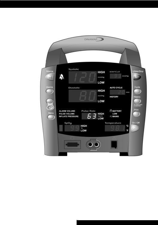
Front Panel ................................................................................................................ |
27 |
Rear Panel ................................................................................................................. |
29 |
Left-Side Panel .......................................................................................................... |
30 |
Right-Side Panel ........................................................................................................ |
30 |
Windows .................................................................................................................... |
31 |
Indicators ................................................................................................................... |
31 |
Operating Modes .................................................................................................... |
31 |
Entering Configuration Mode ............................................................ |
31 |
Parameter Modes .................................................................................................... |
32 |
User Modes ............................................................................................................... |
32 |
Sounds ........................................................................................................................ |
33 |
Power Sources .......................................................................................................... |
34 |
Specifications ............................................................................................................ |
35 |
Mechanical ............................................................................................ |
35 |
Power Requirements ........................................................................... |
35 |
Environmental ....................................................................................... |
36 |
Printer |
|
Description ................................................................................................................ |
41 |

Installing the Paper .................................................................................................. |
41 |
Print Button ............................................................................................................... |
41 |
Printer Alarms ........................................................................................................... |
42 |
Storage ....................................................................................................................... |
42 |
Alarms |
|
Cautions ..................................................................................................................... |
42 |
Alarm Codes ............................................................................................................. |
45 |
Adjusting Alarm Limits ............................................................................................ |
45 |
Alarms Button ....................................................................................... |
45 |
Adjusting the Alarm Volume ................................................................................. |
46 |
Silencing and Acknowledging an Alarm ............................................................. |
46 |
Silence Button ....................................................................................... |
46 |
Alarm Sounds ........................................................................................................... |
46 |
Alarm Detection and Priorities .............................................................................. |
47 |
Limit Alarms ........................................................................................... |
47 |
Parameter Status Alarms ..................................................................... |
48 |
Printer Alarms ........................................................................................ |
48 |
Memory Alarms .................................................................................... |
48 |
Battery Alarms ........................................................................................ |
48 |
System Failure Alarms ......................................................................... |
49 |
Specifications ............................................................................................................ |
50 |
Alarm Message Code Table .................................................................................. |
50 |
History |
|
Description ................................................................................................................ |
55 |
Buttons Associated with History ........................................................................... |
55 |
Erasing Stored History ......................................................................... |
55 |
Windows Associated with History ....................................................................... |
56 |
Indicators Associated with History ...................................................................... |
56 |
BP |
|
Description ................................................................................................................ |
59 |
General Warnings .................................................................................................... |
60 |
General Cautions ..................................................................................................... |
61 |
General Notes ....................................................................................... |
61 |
Buttons Associated with BP ................................................................................... |
62 |
Windows Associated with BP ............................................................................... |
63 |
Indicators Associated with BP ............................................................................... |
63 |
Parameter Modes .................................................................................................... |
63 |
BP Modes of Operation ......................................................................................... |
64 |
Manual BP Determinations ................................................................ |
64 |
Auto Cycle Determinations ................................................................ |
64 |
STAT BP Determinations .................................................................... |
65 |
User Settings ............................................................................................................. |
66 |
Mode Settings ....................................................................................... |
66 |
Limit Settings ......................................................................................... |
66 |
Neonate Settings ..................................................................... |
66 |
Menu Settings ........................................................................................................... |
67 |
Sounds Associated with BP ................................................................................... |
67 |

|
Contents |
Procedures ................................................................................................................ |
67 |
Cuff Connections ................................................................................. |
69 |
Quick-Disconnect .................................................................... |
69 |
Air Hose .................................................................................... |
69 |
Neonate Air Hose ................................................................... |
70 |
Alarms ........................................................................................................................ |
70 |
Critikon US Patents .............................................................................. |
70 |
Specifications ............................................................................................................ |
71 |
Factory Default Settings ...................................................................... |
71 |
SpO2 |
|
NELLCOR® OxiMax® SpO2 ................................................................................ |
75 |
Description ................................................................................................................ |
75 |
General Warnings .................................................................................................... |
76 |
General Cautions ..................................................................................................... |
76 |
General Notes .......................................................................................................... |
77 |
Configuration Settings Associated with SpO2 .................................................. |
77 |
Buttons Associated with SpO2 ............................................................................. |
78 |
Windows Associated with SpO2 .......................................................................... |
78 |
Indicators Associated with SpO2 ......................................................................... |
78 |
Parameter Modes .................................................................................................... |
78 |
User Settings ............................................................................................................. |
79 |
Limit settings .......................................................................................... |
79 |
Menu Settings ........................................................................................................... |
79 |
Sounds Associated with SpO2 .............................................................................. |
79 |
Procedures ................................................................................................................ |
79 |
Warnings .................................................................................................................... |
80 |
Patient safety ......................................................................................... |
80 |
Cautions ..................................................................................................................... |
80 |
Patient safety ......................................................................................... |
80 |
Alarms ........................................................................................................................ |
81 |
Troubleshooting .................................................................................... |
82 |
Specifications ............................................................................................................ |
85 |
Measurement Range ........................................................................... |
85 |
Accuracy and Motion Tolerance ...................................................... |
85 |
Saturation .................................................................................. |
85 |
Pulse Rate................................................................................. |
85 |
NELLCOR® Sensor Accuracy ............................................................ |
85 |
OxiMax® ................................................................................... |
85 |
OxiCliq® ................................................................................... |
85 |
Reusable Sensor Models ....................................................... |
86 |
Factory Default Settings ...................................................................... |
86 |
NELLCOR® Patents ............................................................................. |
87 |
Masimo Set® SpO2 ................................................................................................ |
89 |
Description ................................................................................................................ |
89 |
General Cautions ..................................................................................................... |
90 |
General Notes .......................................................................................................... |
92 |
Configuration Settings Associated with SpO2 .................................................. |
92 |
Buttons Associated with SpO2 ............................................................................. |
93 |
Windows Associated with SpO2 .......................................................................... |
93 |
Indicators Associated with SpO2 ......................................................................... |
93 |

Parameter Modes .................................................................................................... |
93 |
User Settings ............................................................................................................. |
94 |
Limit settings .......................................................................................... |
94 |
Menu Settings ........................................................................................................... |
94 |
Sounds Associated with SpO2 .............................................................................. |
94 |
Procedures ................................................................................................................ |
94 |
Warnings .................................................................................................................... |
95 |
Patient safety ......................................................................................... |
95 |
Cautions ..................................................................................................................... |
95 |
Patient safety ......................................................................................... |
95 |
Alarms ........................................................................................................................ |
96 |
Troubleshooting .................................................................................... |
97 |
Specifications ......................................................................................................... |
100 |
Measurement Range ........................................................................ |
100 |
Accuracy and Motion Tolerance ................................................... |
100 |
Saturation ............................................................................... |
100 |
Pulse Rate .............................................................................. |
100 |
Masimo® Sensor Accuracy ................................................ |
101 |
LNOP ...................................................................................... |
101 |
Resolution .............................................................................. |
101 |
Low Perfusion Performance ............................................... |
101 |
Interfering Substances ...................................................................... |
101 |
Factory Default Settings ................................................................... |
102 |
Masimo Patents ................................................................................. |
102 |
TURBO TEMP® |
|
Description ............................................................................................................. |
105 |
Predictive Mode ................................................................................ |
105 |
Monitor Mode ................................................................................... |
106 |
General Warning .................................................................................................. |
106 |
General Cautions .................................................................................................. |
106 |
Configuration Settings Associated with Temperature ................................... |
107 |
Buttons Associated with Temperature ............................................................. |
107 |
Windows Associated with Temperature .......................................................... |
107 |
Indicators Associated with Temperature ......................................................... |
107 |
Measurement in Progress Indicators ............................................. |
107 |
Predictive Mode ................................................................... |
107 |
Measurement NOT in Progress Indicators .................................. |
108 |
Parameter Modes ................................................................................................. |
109 |
User Settings .......................................................................................................... |
109 |
Menu Settings ........................................................................................................ |
109 |
Sounds Associated with TURBO TEMP® .................................................... |
109 |
Procedures for Oral Predictive Mode Determinations ................................. |
109 |
Procedures for Rectal Predictive Mode Determinations ............................. |
110 |
Procedures for Monitor Mode Determinations |
|
(Axillary Determinations) .................................................................................. |
111 |
Alarms ..................................................................................................................... |
113 |
Specifications ......................................................................................................... |
114 |
Factory Default Settings ................................................................... |
114 |
IVAC® Patents ................................................................................... |
114 |

Contents |
|
Pulse Rate |
|
Description ............................................................................................................. |
117 |
General Notes ....................................................................................................... |
117 |
Buttons Associated with Pulse Rate .................................................................. |
117 |
Windows Associated with Pulse Rate .............................................................. |
118 |
Indicators Associated with Pulse Rate .............................................................. |
118 |
Parameter Modes ................................................................................................. |
118 |
User Settings .......................................................................................................... |
118 |
Limit settings ....................................................................................... |
118 |
Menu Settings ........................................................................................................ |
118 |
Sounds Associated with Pulse Rate .................................................................. |
118 |
Alarms ..................................................................................................................... |
119 |
SpO2 Associated Alarms (If SpO2 is the source) .......... |
119 |
BP Associated Alarms (If BP is the source) ..................... |
119 |
Specifications ......................................................................................................... |
120 |
Factory Default Settings ................................................................... |
120 |
Appendix A: Principles of Noninvasive Blood Pressure |
|
Determination |
|
Principles of Noninvasive Blood Pressure Determination ........................... |
123 |
Systolic Search ................................................................................... |
124 |
Reference Used to Determine NIBP Accuracy .......................... |
125 |
DINAMAP® Monitors With Intra-Arterial Reference |
|
(DINAMAP® Classic Technology) ................................. |
125 |
DINAMAP® Monitors With Auscultatory Reference |
|
(DINAMAP® Auscultatory Technology) ....................... |
125 |
Appendix B: Maintenance |
|
Maintenance .......................................................................................................... |
129 |
Cleaning the Monitor ....................................................................... |
129 |
Materials ................................................................................. |
129 |
Cuff Cleaning and Disinfection ...................................................... |
129 |
General ................................................................................... |
129 |
Materials ................................................................................. |
130 |
Procedure ............................................................................... |
130 |
Temperature Devices ....................................................................... |
130 |
SpO2 Sensors ..................................................................................... |
131 |
Storage and Battery Care .................................................................................... |
131 |
Replacing the Battery ....................................................................... |
132 |
General Caution .................................................................................................... |
133 |
Fuses ........................................................................................................................ |
133 |
Calibration .............................................................................................................. |
133 |
Leak Testing ........................................................................................................... |
134 |
Disposal of Product Waste ................................................................................. |
134 |
Batteries ............................................................................................... |
134 |
Patient Applied Parts ........................................................................ |
134 |
Packaging Material ............................................................................ |
135 |
Monitor ................................................................................................ |
135 |

Appendix C: Connection Details |
|
Connection Details ............................................................................................... |
139 |
Host Port Connector (rear panel) .................................................. |
139 |
Appendix D: Warranty, Service, and Spare Parts |
|
Warranty, Service, and Spare Parts ................................................................... |
143 |
Warranty ................................................................................................................. |
143 |
Assistance and Parts ............................................................................................. |
143 |
Repairs ..................................................................................................................... |
144 |
Packing Instructions ............................................................................................. |
144 |
Service Manuals .................................................................................................... |
144 |
Appendix E: Reorder Codes |
|
Reorder Codes ...................................................................................................... |
147 |
DINAMAP®
ProCare Monitor
Operation Manual
1
DINAMAP® ProCare Monitor
2

DINAMAP® ProCare Monitor
Operation Manual
This manual is for DINAMAP ProCare Monitors models 100, 200, 300, and 400, with or without printers.
•ProCare 100: BP, Pulse
•ProCare 200: BP, Pulse, and Temp
•ProCare 300: BP, Pulse, and SpO2
•ProCare 400: BP, Pulse, Temp, and SpO2
The model of the Monitor determines which parameters are in your monitor. Please refer to applicable sections.
Reissues and Updates
Changes occurring between issues are addressed through Change Information Sheets, Addendums, and replacement pages. If a Change Information Sheet does not accompany this manual, it is correct as printed.
Errors and Omissions
If errors or omissions are found in this manual, please notify: GE Medical Systems Information Technologies
Technical Publications
4502 Woodland Corporate Boulevard Tampa, FL 33614
1-800-558-7044
Part No. 2009360-001 C
The content of this document including all figures and drawings is proprietary information of GE Medical Systems Information Technologies, provided solely for purposes of operation, maintenance or repair, and dissemination for other purposes or copying thereof is prohibited without prior written consent by GE Medical Systems Information Technologies, Tampa, Florida.
Illustrations may show design models; production units may incorporate changes.
3

Hierarchy of Warnings and Cautions
A general warning is a statement that alerts the user to the possibility of injury, death, or other serious adverse reactions associated with the misuse of the device. A warning relates to steps in a procedure.
A general caution is a statement that alerts the user to the possibility of a problem with the device associated with its use or misuse. Such problems include device malfunction, device failure, damage to the device or damage to other property. A caution relates to steps in a procedure.
© Copyright 2002, 2004. GE Medical Systems Information Technologies. All rights reserved.
World Headquarters
GE Medical Systems
Information Technologies, Inc.
8200 West Tower Avenue
Milwaukee, WI 53223 USA
Tel: |
+ 1 414 355 5000 |
|
|
1 |
800 558 5120 (US only) |
Fax: |
+ |
1 414 355 3790 |
European Representative
GE Medical Systems
Information Technologies GmbH
Munzinger Straße 3-5
D-79111 Freiburg
Germany
Tel: |
+ 49 761 45 43 |
- 0 |
Fax: |
+ 49 761 45 43 |
- 233 |
Asia Headquarters
GE Medical Systems
Information Technologies Asia; GE (China) Co., Ltd.
24th Floor, Shanghai MAXDO Center,
8 Xing Yi Road, Hong Qiao Development Zone
Shanghai 200336, P.R. China
Tel: |
+ 86 21 5257 4650 |
|
Fax: |
+ 86 21 5208 2008 |
|
|
4 |
|
|
|
|
|
|
|

Introduction

6

Introduction
About the DINAMAP® ProCare Monitor
The ProCare Monitor provides a small, portable, easy-to-use monitoring alternative for sub-acute hospital and nonhospital settings. The battery-operated Monitor offers noninvasive determination of systolic blood pressure, diastolic blood pressure, mean arterial pressure, pulse rate, oxygen saturation, and temperature. Monitors are available with or without integrated printers. ProCare Monitors are intended for use in various markets, from the physician’s office to sub-acute triage and medical/surgical units.
•ProCare 100: BP, Pulse
•ProCare 200: BP, Pulse, and Temp
•ProCare 300: BP, Pulse, and SpO2
•ProCare 400: BP, Pulse, Temp, and SpO2
The model of the Monitor determines which parameters are in your monitor. Please refer to applicable sections.
Using the ProCare Monitor, a clinician can view, print, and recall clinical data that is derived from each parameter. The Monitor is also capable of alerting the clinician to changes in the patient’s condition or when it is unable to effectively monitor the patient’s condition. All of the main operations of the ProCare Monitor are easy-to-use and only a button-touch away. Please review the factory default settings and, where applicable, enter settings appropriate for your use.
Indications
The ProCare Monitor is intended to monitor one patient at a time in a clinical setting.
Contraindications
This device is not designed, sold, or intended for use except as indicated.
Federal law (U.S.A.) restricts this device to sale by or on the order of a physician.
7

Warnings
•Do not use the ProCare Monitor in the presence of magnetic resonance imaging (MRI) devices. There have been reports of sensors causing patient burns when operating in an MRI environment.
•Do not use the Monitor in the presence of flammable anesthetics.
•To help prevent unintended current return paths with the use of high frequency (HF) surgical equipment, ensure that the HF surgical neutral electrode is properly connected.
•To avoid personal injury, do not perform any servicing unless qualified to do so.
•WARNING: These Monitors should not be used on patients who are connected to cardiopulmonary bypass machines.
•If powering the Monitor from an external power adapter or converter, use only GE Medical Systems
Information Technologies-approved power adapters and converters.
•The Monitor does not include any user-replaceable fuses. Refer servicing to qualified service personnel.
•To reduce the risk of electric shock, do not remove the cover or the back. Refer servicing to a qualified service person.
•If the accuracy of any determination reading is questionable, first check the patient’s vital signs by alternate means and then check the ProCare Monitor for proper functioning.
•Use of portable phones or other radio frequency (RF) emitting equipment near the system may cause unexpected or adverse operation.
•The equipment or system should not be used adjacent to, or stacked with, other equipment. If adjacent or stacked use is necessary, the equipment or system should be tested to verify normal operation in the configuration in which it is being used.
•The use of accessories, transducers and cables other than those specified may result in increased emissions or decreased immunity performance of the equipment or system.
8

Introduction
Cautions
•Do not use replacement batteries other than the type supplied with the Monitor. Replacement batteries are available from GE Medical Systems - Accessories and Supplies.
•The ProCare Monitor is designed to conform to Electromagnetic Compatibility (EMC) standard IEC 601-1-2, 1993 and will operate accurately in conjunction with other medical equipment which also meets this requirement. To avoid interference problems affecting the Monitor, do not use the Monitor in the presence of equipment which does not conform to these specifications.
•Place the ProCare Monitor on a rigid, secure surface. Monitor must only be used with mounting hardware, poles, and stands recommended by GE Medical Systems Information Technologies.
•The weight of the accessory basket contents should not exceed 5 lb (2.7kg).
•Arrange the external AC/DC power converter, air hoses, and all cables carefully so they do not constitute a hazard.
•Verify calibration of BP parameter (temp and pulse oximeter do not require calibration). Ensure that the display is functioning properly before operating the ProCare Monitor.
•Do not immerse the Monitor in water. If the Monitor is splashed with water or becomes wet, wipe it immediately with a dry cloth.
•Do not gas sterilize or autoclave.
•The ProCare Monitor, when used with GE Medical Systems Information Technologies-approved applied parts and accessories, is protected against defibrillator damage.
Note
•The electromagnetic compatibility profile of the ProCare Monitor may change if accessories other than those specified for use with the ProCare Monitor are used.
9

Product Compliance
The DINAMAP® ProCare Monitor is classified in the following categories for compliance with IEC 601-1:
•Internally powered or Class II when powered from external supply
•Transportable
•For continuous operation
•Not suitable for use in the presence of flammable anesthetics
•Not for use in the presence of an oxygen-enriched atmosphere (oxygen tent)
•Type BF applied parts
•IPX1, degree of protection against ingress of water
•Sterilization/Disinfection, see Appendix B
•Software is developed in accordance with IEC 601-1-4.
•This equipment is suitable for connection to public mains via power adaptors as defined in CISPR 11.
•The SpO2 parameter conforms to EN 865:1997 with the exception of Clauses 36, 48, sub-clause 51.108.1and to ISO 9919.
•Defibrillation protected. When used with the recommended accessories, the Monitor is protected against the effects of defibrillator discharge. If monitoring is disrupted by the defibrillation, the Monitor will recover.
DINAMAP® PROCARE MONITOR
CLASSIFIED WITH RESPECT TO ELECTRIC SHOCK, FIRE AND MECHANICAL AND OTHER SPECIFIED HAZARDS ONLY IN ACCORDANCE WITH CAN/CSA C22.2 NO.
601.1. ALSO EVALUATED TO IEC-601-2-30.
|
This product conforms with the essential requirements |
|
of the Medical Device Directive. Accessories without |
|
the CE mark are not guaranteed to meet the Essential |
0086 |
Requirements of the Medical Device Directive. |
|
10
Symbols
The following symbols are associated with the ProCare Monitor.
Note: The model of the Monitor determines which symbols appear on it.
Attention, consult accompanying documents
Silence
Alarms
+ / - Increase / decrease adjustable settings
Menu
Inflate/Stop
Cycle
History
On/Off
Battery Power
External communications port connector
Charging
Defibrillator-proof type BF equipment
External DC power input
Class II equipment according to IEC 60536
11

Packaging label depicting the transportation and storage atmospheric pressure range of 500 to 1060 hPa.
IPX1
The DINAMAP® ProCare Monitor is protected against vertically falling drops of water and conforms with the IEC 529 standard at level of IPX1. Vertically falling drops shall have no harmful effects to the Monitor.
12

Getting Started

14
Getting Started
Unpacking the Monitor and Accessories
Before attempting to use the ProCare Monitor, take a few minutes to become acquainted with the Monitor and its accessories. Unpack the items carefully. This is also a good time to check for any damage or accessory shortage. If there is a problem or shortage, contact GE Medical Systems
Information Technologies.
It is recommended that all the packaging be retained, in case the Monitor must be returned for service in the future.
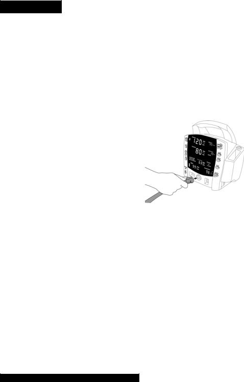
Setting up BP Connections
1.Connect the end of the air hose that has quick-release clips to the BP connector on the front of the Monitor. Make sure that the hose is not kinked or compressed.
Note: To disconnect the hose from the
Monitor, squeeze the quick-release clips together and pull the plug from the BP connector.
2.Select appropriate cuff size. Measure patient’s limb and select appropriately sized cuff according to size marked on cuff or cuff packaging. When cuff sizes overlap for a specified circumference, choose the larger size cuff.
Precaution: Accuracy depends on use of proper size cuff.
3.Inspect cuff for damage. Replace cuff when aging, tearing, or weak closure is apparent. Do not inflate cuff when unwrapped.
Precaution: Do not use cuff if damaged.
4.Connect the cuff to the air hose. Refer to the BP section for complete cuff connection instructions.
Warning: It is mandatory that the appropriate hose and cuff combination be used. Any attempt to modify the hose will inhibit the Monitor from switching between the neonatal and adult measurement modes.
Note: Care should be taken in reconnecting the cuff to a hose, ensuring that threads of the cuff and hose are in alignment and no cross-threading occurs.
15
5.Refer to the BP section of this manual for complete instructions on taking an accurate BP determination.
Note: Use only CRITIKON® Blood Pressure Cuffs. The size, shape, and bladder characteristics can affect the performance of the instrument. Inaccurate readings may occur unless CRITIKON® Blood Pressure Cuffs are used.
Refer to Appendix E for reorder codes.
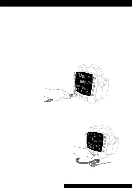
Setting up SpO2 Connections
1.Plug the appropriate SpO2 sensor into the SpO2 sensor extension cable.
2.Then plug the SpO2 sensor extension cable into the SpO2 sensor connector on the Monitor.
3.Refer to the applicable SpO2 section of this manual for complete instructions on monitoring SpO2.
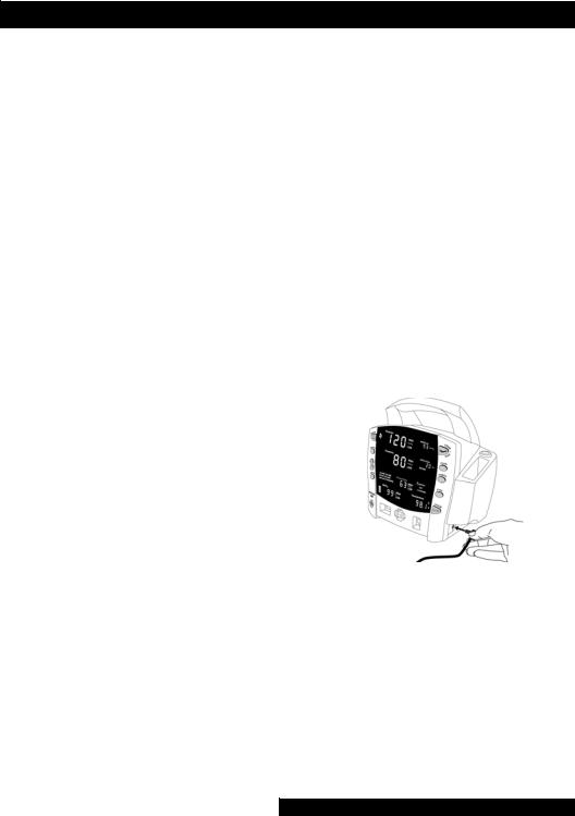
Setting up Temperature Connections
1.Connect the temperature probe cable to the temperature probe connector on the Monitor.
2.Insert the temperature probe into the probe holster at the side of the Monitor.
3.Refer to the
TURBO TEMP®
section of this manual for complete instructions on taking a temperature reading.
16

Getting Started
Setting up the Printer (Installing the Paper)
1.With the Monitor powered on, turn it so that the side with the printer is facing you.
2.While grasping the side of the Monitor, lift the printer door open by placing your thumb in the indented area and pulling. The printer door will pop open.
3.Place the roll of paper into the compartment so that the end of the paper comes off the right-side of the roll (paper is wound around the roll clockwise). Push the roll all the way to the back of the printer cavity, making sure the paper extends out of the printer cavity at least two inches. 4.Firmly press the door to close it. 5.Refer to the Printer section of this manual for complete instructions.
Power Sources
The ProCare Monitor is designed to operate from an internal leadacid battery (see “Specifications” in Product Overview section).
Notes
•The ProCare Monitor is not designed to operate without an internal battery.
•Be sure to unplug the Monitor before transport.
Powering the Monitor: Battery and DC Supply
Prior to each use, inspect the power supply cord to ensure proper connection and condition.
Before the ProCare Monitor is used for the first time, the battery should be charged in the Monitor for at least 8 hours.
17
With external DC power connected, the green CHARGING indicator will light to indicate that the battery is charging.
When the Monitor is operating on battery power and the BATTERY LOW alarm is not active, the BATTERY indicator is backlit green. When the Monitor is operating on battery power and the BATTERY LOW alarm is active, the BATTERY indicator flashes green, the LOW indicator flashes amber, and the medium priority alarm sounds until it is acknowledged. Press the Silence button to acknowledge this alarm. Once it is acknowledged, the indicators continue to flash, but the audible alarm is silenced for 10 minutes. Once the BATTERY LOW condition becomes active, the Monitor should be connected to a DC power supply to recharge the battery (refer to “Power Requirements” in Product Overview section). If the Monitor continues to be used without charging the battery, the Monitor eventually enters a fail-safe mode (E13: BATTERY TOO LOW TO OPERATE). Refer to the Alarms Section for information of an E13 error code.
Battery charging will take place as long as the Monitor remains connected to an external DC power source.
Notes
•To prolong the life of the battery, keep the Monitor connected to a DC power supply
whenever possible. NEVER allow the battery to become
completely discharged. A fully charged battery will power the Monitor for approximately 5 hours. To ensure full charge cycles, replace only with a recommended battery. If the Monitor is to be stored for some time, first charge the battery and then remove it and store it separately from the Monitor.
18

Getting Started
Turning the Monitor On and Off
To turn the ProCare Monitor on, push the power On/Off button.
As the Monitor powers up, it will run a short self-test routine, which will flash all the indicator lights and then beep the warning speaker.
To turn the Monitor off, push the power On/Off button again. This will terminate any measurements that may be in progress and automatically deflate the cuff.
Note: Pressing and holding the On/Off button for 15 seconds will reset the CPU processor. After resetting the CPU processor, check all the unit configuration settings.
Configuration Mode Settings
Monitor settings such as HIGH/LOW alarm settings changed in the Clinical Mode will not be retained after the monitor is powered off. To retain alarm and parameter settings, the changes must be done in the configuration mode. Date/Time settings are also entered in the configuration mode.
To enter the configuration mode: with the Monitor off, press and hold the Menu button at the same time as pressing and holding the On/Off button for 3 seconds. The Monitor enters the configuration mode.
As the monitor turns on in the configuration mode, a brief display appears showing the software revision and the BP technology of the Monitor. These displays appear only during the first part of the power up sequence and are not selectable and cannot be changed.
Display |
Window |
Major software revision |
Systolic |
Minor software revision |
Diastolic |
Type of BP technology |
min |
19

The Menu selections appear in the following order. Refer the each manual section for settings options.
Note: Menu selections for a Masimo unit have three SpO2 settings. Refer to the Masimo SpO2 section for options.
Setting: |
Window |
LED Display |
• Inflate |
|
|
Pressure: |
Diastolic |
XXX (numeric) |
• SpO2 Mode: |
SpO2 |
|
• SpO2 Sat: |
SpO2 |
|
• SpO2* Sensitivity: |
SpO2 |
|
• Temp: |
°C or °F |
|
• Year: |
Systolic |
|
• Month: |
MAP/Cuff |
|
• Day: |
Diastolic |
|
• Hour: |
min |
|
• Minute: |
min |
|
• Mode: |
Systolic |
|
*Masimo units only |
|
|
Setting the Date and Time
To set the date and time on the ProCare Monitor, you must access the configuration mode. Press MENU to skip the default settings that do not require changes. The following list shows the windows in which the date/time settings appear.
Setting: |
Window |
LED Display |
• Year: |
Systolic |
|
• Month: |
MAP/Cuff |
|
• Day: |
Diastolic |
|
• Hour: |
min |
|
• Minute: |
min |
|
Procedures
1.Press the Menu button to move from one setting to another. Use the +/- buttons to increment or decrement the setting.
20
 Loading...