


 Loading...
Pressure measurement for research & industry
Druck Limited
Fir Tree Lane
Groby
Leicester LE6 0FH
England
Tel: 0116 231 7100
CERTIFICATE RELATED DRAWING
NOT TO BE MODIFIED WITHOUT
THE APPROVAL OF THE CERTIFICATION ENGINEER
APPROVED: |
M T CONCANNON |
CERTIFICATES: |
Baseefa10ATEX0010X |
|
Baseefa10ATEX0012X |
|
IECEx BAS 10.0002X |
|
IECEx BAS 10.0004X |
DPI 620-IS
Advanced Modular Calibrator
User Manual
K0460
Druck Limited 2010
This document is the property of Druck Limited and may not, either in part or whole, be copied or otherwise reproduced, communicated in any way to third parties, nor stored in any data processing system, without the express written authority of Druck Limited.
Page 1 of 98 |
K0460 Issue 1 |

|
|
|
|
|
Amendment Record |
||
|
|
|
|
|
|
|
|
|
|
|
|
|
|
|
|
|
Iss No |
Date |
C/N No |
Originator |
Typed |
Workflow |
Amendments |
|
|
||||||
|
|
|
|
|
|
No. |
|
|
1 |
21/07/10 |
N/A |
Robert Lee |
Robert Lee |
149146 |
New document |
|
|
|
|
|
|
|
|
|
|
|
|
|
|
|
|
|
|
Approvals |
|
|
|
|
|
|
|
|
|
|
Engineering |
Engineering (Certification) |
|
|
G DOCHERTY |
M CONCANNON |
|
|
|
|
|
|
Marketing |
Technical Communications |
|
|
M SHELTON |
R LEE |
|
|
|
|
|
|
|
|
|
Page 2 of 98 |
K0460 Issue 1 |
Print Instructions: K0460
•Finished Size: A5 Portrait (148 x 210 mm)
•Print in colour throughout (covers + text), saddle stitched.
•Cover to 285 gsm, content to 100 gsm.
THIS HARDCOPY IS NOT TO BE USED AS CAMERA COPY.
Page 3 of 98 |
K0460 Issue 1 |
Page 4 of 98 |
K0460 Issue 1 |
GE
Measurement & Control Systems
Druck DPI 620-IS
advanced modular calibrator
user manual - K0460
Issue 1
Quick reference data
A1.1 DPI 620-IS: Channel 1 (CH1)
Measure (M) / Source (S) / Power (P)
±30 V (M) |
±55 mA (M) |
|
|
0 to 12 V (S) |
0 to 24 mA (S) |
|
|
±2000 mV (M) |
8 RTDs (M/S): Pt1000, Pt500, Pt200, Pt100(385), |
0 to 2000 mV (S) |
Pt50, D 100, Ni 100, Ni 120 |
|
|
0 to 4000 Ω (M/S) |
12 Thermocouples (M/S): K, J, T, B, R, S, E, N, L, U, C, D |
|
|
0 to 5 kHz (M/S) |
|
|
|
Switch (M) |
|
|
|
Pulse counting and |
|
sourcing up to 5k. |
|
|
|
A1.2 DPI 620-IS: Channel 2 (CH2)
±30 V (M) |
0 to 20 mA (S) |
|
|
±2000 mV (M) |
24 V nominal; maximum: 20 mA |
|
|
±55 mA (M) |
Switch (M) |
|
|
A1.3 DPI 620-IS + MC 620-IS + PM 620-IS
Pressure* (M)
Gauge: 25 mbar to 200 bar (0.36 to 3000 psi).
Absolute: 350 mbar to 1000 bar (5 to 15000 psi).
Note: Maximum pneumatic pressure: 500 bar (7250 psi).
*Caution: To prevent damage to the PM 620-IS module, only use it within the specified pressure limit on the label.
Copyright
Trademarks
© 2010 General Electric Company. All rights reserved.
Microsoft and Windows are either registered trademarks or trademarks of Microsoft Corporation in the United States and/or other countries.
HART® is a registered trademark of the HART
Communications Foundation.
All product names are trademarks of their respect ive companies.
ii

Issue 1
Safety
General warnings
Before using the instrument, read and understand all the related data. This includes: the applicable local safety procedures, this publication, and the instructions for any accessories/options/equipment.
 WARNING
Electrical warnings
Pressure warnings
•It is dangerous to ignore the specified limits for the instrument or its related accessories. Do not use the instrument or accessory if it is not in its normal condition. Use the applicable protection and obey all safety precautions.
•To prevent electrical shocks or damage to the instrument, do not connect more than 30V between the terminals, or between the terminals and the ground (earth).
•This instrument uses a Ni-MH battery pack. To prevent an explosion or fire, do not short circuit, do not disassemble, keep it safe from damage. For operating conditions, see Table 11-1.
•To prevent battery leakage or heat generation, only use the battery charger and power supply in the temperature range 0 to 40°C (32 to 104°F). For operating conditions, see Table 11-1.
•To make sure the display shows the correct data, disconnect the test leads before setting the power to on or change to another measure or source function.
When using a pressure option with the DPI 620-IS calibrator, these warnings are also applicable:
•Some liquid and gas mixtures are dangerous. This includes mixtures that occur because of contamination. Make sure that the equipment is safe to use with the necessary media.
•Pressurized gases and fluids are dangerous. Before connecting or disconnecting pressure equipment, safely release all the pressure.
•To prevent a dangerous release of pressure, make sure that all the related pipes, hoses and equipment have the correct pressure rating, are safe to use and are correctly attached.
[EN] English - K0460 |
Safety iii |
Issue 1
|
• It is dangerous to attach an external source of pressure |
|
to a PM 620-IS series pressure station. Use only the |
|
specified mechanisms to set and control the pressure |
|
in the pressure station. |
Cautions |
To prevent damage to the display, do not use sharp |
|
objects on the touch-screen. |
|
To prevent damage to the PM 620-IS module, only use it |
|
within the specified pressure limit on the label. |
|
Before starting an operation or procedure in this publication, |
|
the user must have the necessary skills (if necessary, with |
|
qualifications from an approved training establishment). Follow |
|
good engineering practice at all times. |
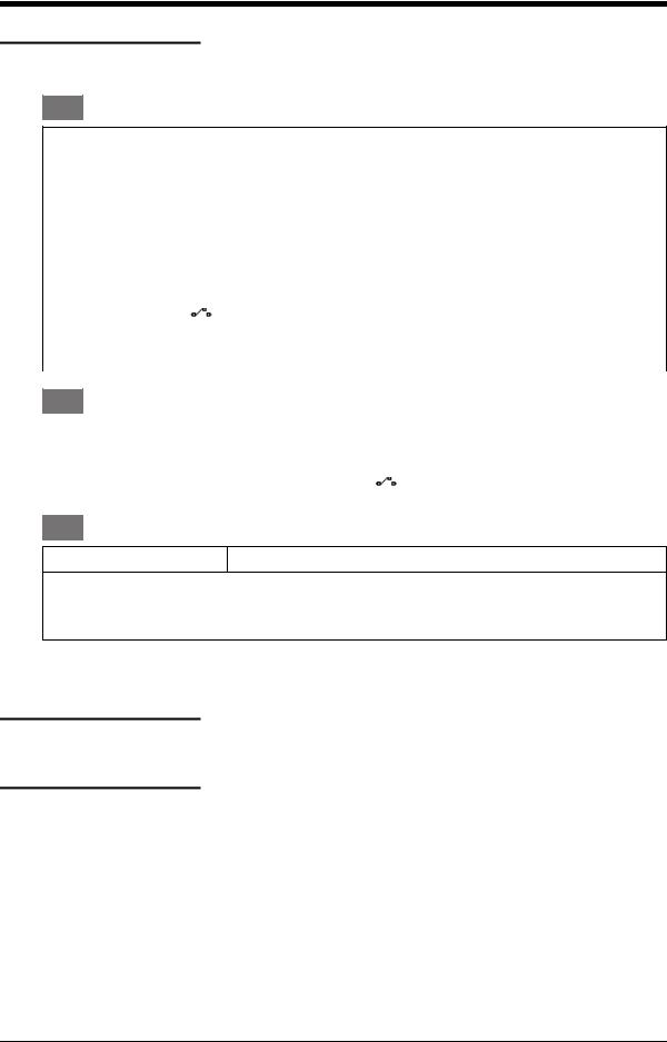
Marks and symbols on the instrument
Complies with European |
|
|
Warning - refer to the |
Union directives |
|
|
manual |
|
|
|
|
Read the manual |
|
|
USB port: Mini type B |
|
|
|
connector |
|
|
|
|
Ground (Earth) |
|
|
ON/OFF |
|
|
|
|
Do not dispose of this product as household waste. Refer to Chapter 9 (Maintenance procedures).
More marks and symbols are specified in this manual: electrical marks, display symbols (Chapter 1); pressure related marks and symbols (Chapter 4).
iv Safety |
K0460 - [EN] English |

Issue 1
Overview
DPI 620-IS
MC 620-IS
PM 620-IS
Pressure calibrator
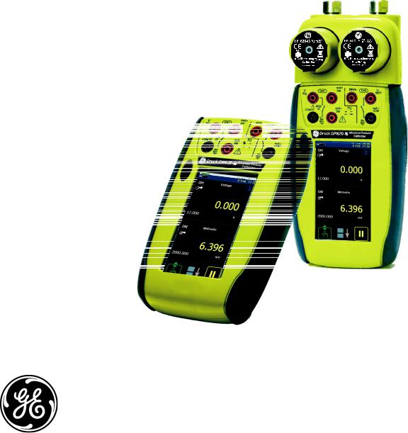
The intrinsically safe, advanced modular calibrator (AMC) is part of a set of hand-held modules that can be quickly put together to include a wide range of calibrator functions.
Advanced modular calibrator, DPI 620-IS (this user manual): This is a battery-powered instrument for electrical measure and source operations and HART® communications; see Table A1 (front cover). It also supplies the power and user interface functions for all the add-on modules. Use the touch-screen to display up to six different parameters.
Pressure module carrier, MC 620-IS (this user manual):
This attaches to the DPI 620-IS calibrator to make a fully integrated pressure indicator instrument. To measure and display pneumatic or hydraulic pressures, up to two interchangeable pressure modules can be used at a time.
When not in use fit blanking device (part number 191-369).
Pressure modules, PM 620-IS (this user manual):
Optional item. These modules attach to the pressure module carrier (MC 620-IS) or to a pressure station (PV 62x-IS) to give the DPI 620-IS calibrator the necessary pressure measurement functionality. They are fully interchangeable “plug and play” modules with no initial set-up or user calibration.
Pressure stations, PV 62x-IS (user manual - K0462:
Optional item. To make a fully integrated pressure calibrator, attach the DPI 620-IS calibrator to one of the three pressure stations:
•two pneumatic pressure stations gives an accurate and controlled pressure and vacuum conditions:
PV 621-IS: -950 mbar to 20 bar (-13.5 to 300 psi) version PV 622-IS: -950 mbar to 100 bar (-13.5 to 1500 psi) version
•one hydraulic pressure station gives an accurate and controlled hydraulic pressure conditions:
PV 623-IS: 0 to 1000 bar (15000 psi)
The advanced modular calibrator (AMC-IS) and the pressure module (PM 620-IS) are part of a set of hand-held modules that can be quickly put together to include a wide range of calibrator functions.
To give the attached equipment overpressure protection, there are pressure relief valves (PRV) available for all the pressure stations.
[EN] English - K0460 |
Overview v |

Issue 1
Summary of functions
Software (this user manual): The DPI 620-IS calibrator includes the following software:
• documenting software • HART® communications software
Other accessories and options: For part numbers (P/N), refer to Section 1.4 (Accessories).
This table gives a summary of the available functions with the DPI 620-IS calibrator.
DPI 620-IS - Calibrator functions
Function
Easy to read, Active Matrix Organic Light Emitting Diode Display in colour.
No keys: the touch-screen has large buttons for finger operation.
Rechargeable NiMH battery with enhanced power control for prolonged battery life.
*Measure current (mA), voltage (Volts/mV), frequency (Hz/pulse count).
*Supply current (mA), voltage (Volts/mV), frequency (Hz/pulse count).
*Measure/simulate:
-a Resistance Temperature Detector (RTD): Ω or °C/°F
-a thermocouple (TC): mV or °C/°F
-a resistor (Ω)
Cold Junction (CJ) compensation: Automatic/Manual.
Step/Ramp functions: Automatic/Manual.
Switch test and condition indicator (open/closed).
Language selection (see Section 2.8 (Menu sequence)).
Universal Serial Bus (USB) communications ports: For computer communications, external modules.
† Windows® CE operating system.
** Measure pressure/Leak test: See pressure accessories.
Documenting software to give an analysis of a device calibration.
Set-up function to save and recall personal settings, instrument calibration settings and other standard instrument operations.
vi Summary of functions |
K0460 - [EN] English |
Issue 1
DPI 620-IS - Calibrator functions (Continued)
Function
HART® (Highway Addressable Remote Transducer) communications software to set up and calibrate devices that use the HART field communications protocol.
Other functions: Hold, maximum/minimum/average, filter, tare, adjustable backlight, alarm indication (on the display), automatic power off.
*Refer to the datasheet
**Optional item
† Factory configured
About this manual
Example buttons:
This user manual is set up for use on a computer or similar device that has the necessary software to read a Portable Document Format (PDF) file.
It is supplied as a PDF on a compact disc (CD) but can be copied or saved onto a computer or similar device that has the necessary PDF software.
To navigate between related items of information, the user manual includes cross references and links (shown in blue); for example:
•text cross references: ... Figure 1-1; Table 11-1; Chapter 1; Section 1.4 (Accessories)
Note: Moving the PDF software cursor over an item that has a link, the cursor symbol normally changes.
Click on a link, and the PDF software shows the applicable page. To help navigate through the links use, the PDF software which usually includes these buttons:
Previous view: To go back to a previous page selection.
Next view: In a sequence of page selections, this moves forward to the next page.
Note: Different software versions have different buttons. In some versions, it is also necessary to set up the “View” to include these “Tools” in the “Page Navigation Toolbar”; refer to the PDF software documentation.
[EN] English - K0460 |
About this manual vii |

Issue 1
viii About this manual |
K0460 - [EN] English |

Issue 1
Table of Contents
Quick reference data . . . . . . . . . . . . . . . . . . . . . . . . . . . . . . . . . . . . . . . . . . . . . . . . . . . . . . . .ii Trademarks . . . . . . . . . . . . . . . . . . . . . . . . . . . . . . . . . . . . . . . . . . . . . . . . . . . . . . . . . . . . . . .ii Safety. . . . . . . . . . . . . . . . . . . . . . . . . . . . . . . . . . . . . . . . . . . . . . . . . . . . . . . . . . . . . . . . . . . iii Overview . . . . . . . . . . . . . . . . . . . . . . . . . . . . . . . . . . . . . . . . . . . . . . . . . . . . . . . . . . . . . . . . .v Summary of functions . . . . . . . . . . . . . . . . . . . . . . . . . . . . . . . . . . . . . . . . . . . . . . . . . . . . . . vi About this manual . . . . . . . . . . . . . . . . . . . . . . . . . . . . . . . . . . . . . . . . . . . . . . . . . . . . . . . . . vii Table of Contents . . . . . . . . . . . . . . . . . . . . . . . . . . . . . . . . . . . . . . . . . . . . . . . . . . . . . . . . . . ix
Chapter 1: Instrument parts, accessories and options
1.1 Introduction . . . . . . . . . . . . . . . . . . . . . . . . . . . . . . . . . . . . . . . . . . . . . . . . . . . . . . . . 1-1 1.2 The instrument. . . . . . . . . . . . . . . . . . . . . . . . . . . . . . . . . . . . . . . . . . . . . . . . . . . . . . 1-1 1.3 The display . . . . . . . . . . . . . . . . . . . . . . . . . . . . . . . . . . . . . . . . . . . . . . . . . . . . . . . . . 1-3 1.4 Accessories . . . . . . . . . . . . . . . . . . . . . . . . . . . . . . . . . . . . . . . . . . . . . . . . . . . . . . . . 1-4
Chapter 2: Prepare the instrument
2.1 Introduction . . . . . . . . . . . . . . . . . . . . . . . . . . . . . . . . . . . . . . . . . . . . . . . . . . . . . . . . 2-1 2.2 Initial checks . . . . . . . . . . . . . . . . . . . . . . . . . . . . . . . . . . . . . . . . . . . . . . . . . . . . . . . 2-1 2.3 Initial procedures. . . . . . . . . . . . . . . . . . . . . . . . . . . . . . . . . . . . . . . . . . . . . . . . . . . . 2-1 2.4 Power supply . . . . . . . . . . . . . . . . . . . . . . . . . . . . . . . . . . . . . . . . . . . . . . . . . . . . . . . 2-1 2.5 The battery . . . . . . . . . . . . . . . . . . . . . . . . . . . . . . . . . . . . . . . . . . . . . . . . . . . . . . . . . 2-2
2.5.1 Battery condition . . . . . . . . . . . . . . . . . . . . . . . . . . . . . . . . . . . . . . . . . . . . . . . 2-2 2.5.2 Install the battery . . . . . . . . . . . . . . . . . . . . . . . . . . . . . . . . . . . . . . . . . . . . . . 2-2 2.5.3 Charge the battery . . . . . . . . . . . . . . . . . . . . . . . . . . . . . . . . . . . . . . . . . . . . . 2-3 2.5.4 Charge times . . . . . . . . . . . . . . . . . . . . . . . . . . . . . . . . . . . . . . . . . . . . . . . . . 2-3 2.5.5 Operating time . . . . . . . . . . . . . . . . . . . . . . . . . . . . . . . . . . . . . . . . . . . . . . . . 2-4
2.6 |
Power on or off . . . . . . . . . . . . . . . . . . . . . . . . . . . . . . . . . . . . . . . . . . . . . . . . . . . . . |
2-4 |
|
2.7 |
Display operation. . . . . . . . . . . . . . . . . . . . . . . . . . . . . . . . . . . . . . . . . . . . . . . . . . . . |
2-4 |
|
|
2.7.1 Change items in a list . . . . . . . . . . . . . . . . . . . . . . . . . . . . . . . . . . . . . . . . . . . |
2-5 |
|
|
2.7.2 |
Change numeric values . . . . . . . . . . . . . . . . . . . . . . . . . . . . . . . . . . . . . . . . . |
2-5 |
|
2.7.3 |
Enter text . . . . . . . . . . . . . . . . . . . . . . . . . . . . . . . . . . . . . . . . . . . . . . . . . . . . |
2-6 |
|
2.7.4 |
Maximise/minimise a window . . . . . . . . . . . . . . . . . . . . . . . . . . . . . . . . . . . . . |
2-6 |
2.8 Menu sequence . . . . . . . . . . . . . . . . . . . . . . . . . . . . . . . . . . . . . . . . . . . . . . . . . . . . . 2-7
2.8.1 Procedure to set the basic operations: . . . . . . . . . . . . . . . . . . . . . . . . . . . . . . 2-8 2.8.2 Procedure to see the instrument status . . . . . . . . . . . . . . . . . . . . . . . . . . . . . 2-9 2.8.3 Procedures to make Task selections . . . . . . . . . . . . . . . . . . . . . . . . . . . . . . . 2-9 2.8.4 Set a function . . . . . . . . . . . . . . . . . . . . . . . . . . . . . . . . . . . . . . . . . . . . . . . . 2-11 2.8.5 Set the units . . . . . . . . . . . . . . . . . . . . . . . . . . . . . . . . . . . . . . . . . . . . . . . . . 2-12 2.8.6 Set up a utility:Maximum/Minimum/Average example . . . . . . . . . . . . . . . . . 2-12
[EN] English - K0460 |
Table of Contents ix |

Issue 1
2.9 Measure and source operations. . . . . . . . . . . . . . . . . . . . . . . . . . . . . . . . . . . . . . . 2-13
2.9.1 Set the Process options (measure) . . . . . . . . . . . . . . . . . . . . . . . . . . . . . . . 2-14 2.9.2 Set the Automation options (source) . . . . . . . . . . . . . . . . . . . . . . . . . . . . . . 2-16 2.9.3 Set the Observed settings (source) . . . . . . . . . . . . . . . . . . . . . . . . . . . . . . . 2-17
2.10 The Advanced menu options . . . . . . . . . . . . . . . . . . . . . . . . . . . . . . . . . . . . . . . . . 2-18
2.10.1 Advanced: Calibration options . . . . . . . . . . . . . . . . . . . . . . . . . . . . . . . . . . . 2-18 2.10.2 Advanced Setup options. . . . . . . . . . . . . . . . . . . . . . . . . . . . . . . . . . . . . . . . 2-19
2.11 The Help menu . . . . . . . . . . . . . . . . . . . . . . . . . . . . . . . . . . . . . . . . . . . . . . . . . . . . . 2-20
Chapter 3: Electrical and IDOS operations
3.1 Introduction . . . . . . . . . . . . . . . . . . . . . . . . . . . . . . . . . . . . . . . . . . . . . . . . . . . . . . . . 3-1 3.2 Measure and source operations. . . . . . . . . . . . . . . . . . . . . . . . . . . . . . . . . . . . . . . . 3-1
3.2.1 Procedure overview . . . . . . . . . . . . . . . . . . . . . . . . . . . . . . . . . . . . . . . . . . . . 3-1 3.2.2 Example procedure: Measure or source current . . . . . . . . . . . . . . . . . . . . . . 3-2 3.2.3 Example procedure: Measure DC voltage . . . . . . . . . . . . . . . . . . . . . . . . . . . 3-3 3.2.4 Example procedure: Source DC voltage (CH1) . . . . . . . . . . . . . . . . . . . . . . . 3-3 3.2.5 Example procedure: Measure or source frequency signals . . . . . . . . . . . . . . 3-4 3.2.6 Example procedure: Measure or simulate an RTD (or Resistance) . . . . . . . . 3-5 3.2.7 Example procedure: Measure or simulate a thermocouple (or TC mV) . . . . . 3-6 3.2.8 Example procedure: Switch test . . . . . . . . . . . . . . . . . . . . . . . . . . . . . . . . . . . 3-8
3.3 Error indications . . . . . . . . . . . . . . . . . . . . . . . . . . . . . . . . . . . . . . . . . . . . . . . . . . . 3-10
Chapter 4: Pressure indicator operation (MC 620-IS)
4.1 Introduction . . . . . . . . . . . . . . . . . . . . . . . . . . . . . . . . . . . . . . . . . . . . . . . . . . . . . . . . 4-1 4.2 Parts and assembly . . . . . . . . . . . . . . . . . . . . . . . . . . . . . . . . . . . . . . . . . . . . . . . . . . 4-1
4.2.1 Assembly instructions . . . . . . . . . . . . . . . . . . . . . . . . . . . . . . . . . . . . . . . . . . . 4-2
4.3 Pressure connections . . . . . . . . . . . . . . . . . . . . . . . . . . . . . . . . . . . . . . . . . . . . . . . . 4-2
4.3.1 Procedure (to attach external equipment) . . . . . . . . . . . . . . . . . . . . . . . . . . . 4-2
4.4 Measure pressure . . . . . . . . . . . . . . . . . . . . . . . . . . . . . . . . . . . . . . . . . . . . . . . . . . . 4-3
4.4.1 Procedure overview . . . . . . . . . . . . . . . . . . . . . . . . . . . . . . . . . . . . . . . . . . . . 4-3 4.4.2 Set-up a Leak Test . . . . . . . . . . . . . . . . . . . . . . . . . . . . . . . . . . . . . . . . . . . . . 4-4 4.4.3 Set the pressure module to zero. . . . . . . . . . . . . . . . . . . . . . . . . . . . . . . . . . . 4-5 4.4.4 Example procedure: Measure pressure . . . . . . . . . . . . . . . . . . . . . . . . . . . . . 4-5
4.5 Error indications . . . . . . . . . . . . . . . . . . . . . . . . . . . . . . . . . . . . . . . . . . . . . . . . . . . . 4-6
Chapter 5: Instrument communications
5.1 Introduction . . . . . . . . . . . . . . . . . . . . . . . . . . . . . . . . . . . . . . . . . . . . . . . . . . . . . . . . 5-1 5.2 Connect to a computer (USB). . . . . . . . . . . . . . . . . . . . . . . . . . . . . . . . . . . . . . . . . . 5-1
x Table of Contents |
K0460 - [EN] English |

Issue 1
Chapter 6: Datalog operation
6.1 Introduction . . . . . . . . . . . . . . . . . . . . . . . . . . . . . . . . . . . . . . . . . . . . . . . . . . . . . . . . 6-1 6.2 Set-up . . . . . . . . . . . . . . . . . . . . . . . . . . . . . . . . . . . . . . . . . . . . . . . . . . . . . . . . . . . . . 6-1 6.3 Data Logging . . . . . . . . . . . . . . . . . . . . . . . . . . . . . . . . . . . . . . . . . . . . . . . . . . . . . . . 6-3 6.4 Data handling . . . . . . . . . . . . . . . . . . . . . . . . . . . . . . . . . . . . . . . . . . . . . . . . . . . . . . . 6-3
Chapter 7: Documenting functions
7.1 Introduction . . . . . . . . . . . . . . . . . . . . . . . . . . . . . . . . . . . . . . . . . . . . . . . . . . . . . . . . 7-1 7.2 Analysis . . . . . . . . . . . . . . . . . . . . . . . . . . . . . . . . . . . . . . . . . . . . . . . . . . . . . . . . . . . 7-1 7.3 Run a procedure . . . . . . . . . . . . . . . . . . . . . . . . . . . . . . . . . . . . . . . . . . . . . . . . . . . . 7-2
Chapter 8: HART® device operations
8.1 Introduction . . . . . . . . . . . . . . . . . . . . . . . . . . . . . . . . . . . . . . . . . . . . . . . . . . . . . . . . 8-1
8.2 About HART . . . . . . . . . . . . . . . . . . . . . . . . . . . . . . . . . . . . . . . . . . . . . . . . . . . . . . . . 8-1
8.3 HART Connections . . . . . . . . . . . . . . . . . . . . . . . . . . . . . . . . . . . . . . . . . . . . . . . . . . 8-7
8.3.1 Power supply from the calibrator . . . . . . . . . . . . . . . . . . . . . . . . . . . . . . . . . . 8-7 8.3.2 External loop power . . . . . . . . . . . . . . . . . . . . . . . . . . . . . . . . . . . . . . . . . . . . 8-8 8.3.3 Communicator attached to a network . . . . . . . . . . . . . . . . . . . . . . . . . . . . . . . 8-9 8.3.4 Failed to find device . . . . . . . . . . . . . . . . . . . . . . . . . . . . . . . . . . . . . . . . . . . 8-10
Chapter 9: Maintenance procedures
9.1 Introduction . . . . . . . . . . . . . . . . . . . . . . . . . . . . . . . . . . . . . . . . . . . . . . . . . . . . . . . . 9-1 9.2 Clean the unit . . . . . . . . . . . . . . . . . . . . . . . . . . . . . . . . . . . . . . . . . . . . . . . . . . . . . . . 9-1 9.3 Replace the batteries. . . . . . . . . . . . . . . . . . . . . . . . . . . . . . . . . . . . . . . . . . . . . . . . . 9-1
Chapter 10: Calibration procedures
10.1 Introduction . . . . . . . . . . . . . . . . . . . . . . . . . . . . . . . . . . . . . . . . . . . . . . . . . . . . . . . 10-1 10.2 Before starting . . . . . . . . . . . . . . . . . . . . . . . . . . . . . . . . . . . . . . . . . . . . . . . . . . . . . 10-1 10.3 Selection sequence . . . . . . . . . . . . . . . . . . . . . . . . . . . . . . . . . . . . . . . . . . . . . . . . . 10-2 10.4 Procedures (CH1/CH2): Current (measure). . . . . . . . . . . . . . . . . . . . . . . . . . . . . . 10-3 10.5 Procedures (CH1/CH2): Current (source) . . . . . . . . . . . . . . . . . . . . . . . . . . . . . . . 10-3 10.6 Procedures (CH1/CH2): DC mV/Volts (measure). . . . . . . . . . . . . . . . . . . . . . . . . . 10-5 10.7 Procedures (CH1 mV (measure)/Volts (source) . . . . . . . . . . . . . . . . . . . . . . . . . . 10-6 10.8 Procedures (CH1): Frequency (measure/source) . . . . . . . . . . . . . . . . . . . . . . . . . 10-7 10.9 Procedures (CH1): Frequency amplitude (source) . . . . . . . . . . . . . . . . . . . . . . . . 10-9 10.10 Procedures (CH1): Resistance (measure) . . . . . . . . . . . . . . . . . . . . . . . . . . . . . 10-10 10.11 Procedures (CH1): Resistance (source) . . . . . . . . . . . . . . . . . . . . . . . . . . . . . . 10-11 10.12 Procedures (CH1): TC mV (measure or source) . . . . . . . . . . . . . . . . . . . . . . . . 10-12 10.13 Procedures (CH1): CJ (measure) . . . . . . . . . . . . . . . . . . . . . . . . . . . . . . . . . . . . 10-13 10.14 Procedures (CH1): Pressure indicator modules (PM 620-IS). . . . . . . . . . . . . . 10-14
[EN] English - K0460 |
Table of Contents xi |

Issue 1
Chapter 11: General specification
11.1 Introduction . . . . . . . . . . . . . . . . . . . . . . . . . . . . . . . . . . . . . . . . . . . . . . . . . . . . . . . 11-1
Customer service. . . . . . . . . . . . . . . . . . . . . . . . . . . . . . . . . . . . . . . . . . . . . . . . . . . . . Back cover
xii Table of Contents |
K0460 - [EN] English |
1.1Introduction
1.2The instrument
Chapter 1: Instrument parts, accessories and options
This chapter gives a description of the different parts of the instrument and the accessories/options available.
2 |
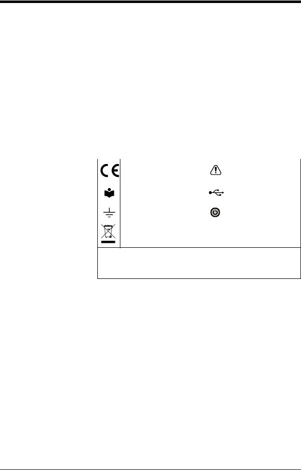
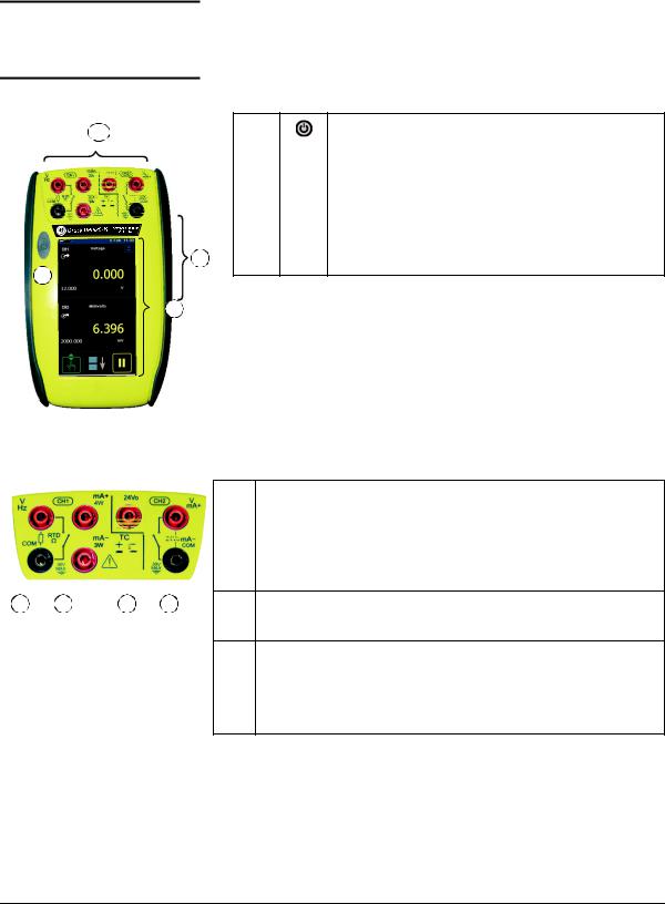
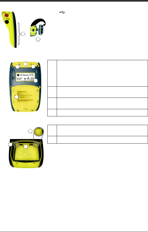
1. |
|
On or off button. Refer to “Quick Reference”. |
|
|
|
|
|
|
|
|
|
2. |
CH1 |
Connectors for Channel 1 |
|
|
|
|
|
|
CH2 |
Connectors channel 2 |
|
|
|
|
|
3. |
USB |
Connector. |
|
|
|
|
3 |
4. |
|
Display screen. |
1
4
Figure 1-1: General view of the instrument
2 |
a |
b |
c |
Figure 1-2: CH1/CH2 connections
2a Channel 1 (CH1) connectors for:
V: volts/mV DC; Hz: frequency and counts/min, counts/hour (cpm/cph); Ω: resistance; RTD: 2-wire, 3-wire (3W), 4-wire (4W) resistance temperature detectors;  : switch operation; mA+, mA-: current. Refer to Chapter 3 (Electrical operations).
2b Channel 1 (CH1) connectors for thermocouples (TC). Refer to Chapter 3.
2c Isolated channel 2 (CH2) connectors for:
V: volts/mV DC; mA+, mA-: current; 24Vo: 24V loop power supply;  : switch operation; refer to Chapter 3. For HART connections,
refer to Chapter 8.
[EN] English - K0460 |
Instrument parts, accessories and options 1-1 |
Issue 1
3. |
: USB mini Type B connector for communication with a |
|
computer. |
|
|
|
|
3
5
Figure 1-3:
The USB connector
7 |
5. |
Cover for the USB connector (Figure 1-3). For IP65, press it fully |
|
6 |
6 |
|
into the recess over the connectors. |
|
|
|
|
|
6. |
Two connection points to attach the pressure module carrier |
|
|
8 |
|
(MC 620-IS); refer to Chapter 4 (Pressure indicator operation |
|
|
(MC 620-IS)). |
|
|
|
|
|
7.Electrical connections for the pressure module carrier (MC 620-IS) or a pressure station (PV 62x-IS).
9
8.Label: model, date of manufacture (DoM: month/year), serial number (S/N); manufacturer: name, address, website
9.Compartment cover for the battery.
Figure 1-4: Bottom view (cover attached)
10.Two position guides for the battery. Refer to Section 2.5.2 (Install
10 |
the battery). |
11.Electrical connections for the battery.
10
11
Figure 1-5: Bottom view (cover/battery removed)
1-2 Instrument parts, accessories and options |
K0460 - [EN] English |
Issue 1
1.3 The display
This is a OLED with a colour display with a touch-screen. To make a selection, lightly tap on the applicable display area with a finger; see Section 2.7 (Display operation).
a |
c |
b |
||
1 |
|
|
f |
|
|
|
|||
d |
e |
|||
|
||||
2
g 
h
3
4
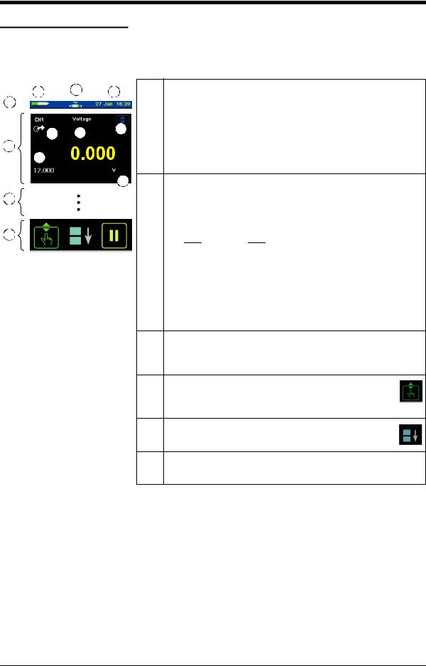
Figure 1-6: Example display
1.Status bar: This includes:
a. Battery indicator |
b. Date and time |
c.Indicators for a Pressure connection, a HART protocol resistor, Datalog and wireless operation; for example:
 : Pressure;
  : HART
2.CH1: Window for the channel 1 settings and values; see Section 2.8.1.
d. Measure or source indication:

 : Measure;
 : Source
e.Function (voltage, current, pressure ...)
f.Source process indicator; for example:
 : Nudge;
  : Span check;
  : Ramp
g. Full scale (FS) range |
h. Function units |
3.Other windows: The number of windows seen on the display is set by the number of task selections and external modules you are working with (maximum: 6); see Section 2.7.
4.Tap this button to set up the Task, set up the instrument (Configure) and to access Help (?). see Section 2.8 (Menu sequence).
5.Tap this button to maximise each of the available windows in sequence; see Section 2.7.4
6.Pause (II) or Play (X): Tap (II) to hold (freeze) all the data on the display. To release the display and continue, tap (X).
[EN] English - K0460 |
Instrument parts, accessories and options 1-3 |
Issue 1
1.4 Accessories
1 |
2 |
3 |
|
4 |
6 |
|
|
5 |
|
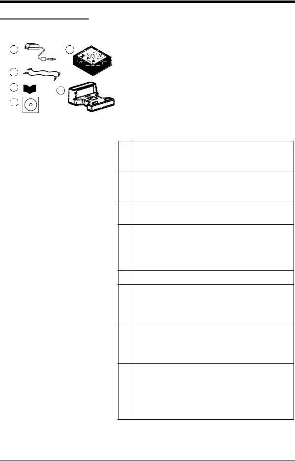
Figure 1-7: Accessories included
1. |
IO620IS-CHARGER |
|
|
2. |
IO620-IS BATTERY. Ni-MH battery |
|
|
3. |
209-539. Set of six electrical test leads |
|
|
4. |
K0461. Safety and quick reference guide |
|
|
5. |
UD-0004. CD with the user manual |
|
|
6. |
IO620IS CRADLE |
|
|
7.IO620-CASE-1. Fabric carry case with a belt loop, shoulder strap and a large pocket for accessories. It can hold one DPI 620-IS calibrator.
8.IO620-CASE-2. Fabric carry case. It can hold a set of units: one DPI 620-IS calibrator; one MC 620-IS module carrier; PM 620-IS modules and related accessories.
9.IO620-USB-PC. USB mini Type B cable to connect the DPI 620-IS calibrator to a computer.
10.IO620-FIELD-CAL. Intecal field calibration manager. Use the documenting functions in the calibrator with elements of the Intecal database; set-up new device records and procedures; upload Intecal data to your computer database.
11.Pressure modules (PM 620-IS); refer to the datasheet.
12.Pneumatic hose kit rated to 400 bar (5800 psi) with “Quick fit” connectors for the test port.
IO620-HOSE-P1-IS: 1 metre (≈ 39”) IO620-HOSE-P2-IS: 2 metre (≈ 78”)
13.Hydraulic hose kit rated to 1000 bar (15000 psi) with “Quick fit” connectors for the test port. IO620-HOSE-H1-IS: 1 metre (≈ 39”) IO620-HOSE-H2-IS: 2 metre (≈ 78”)
14.Pressure adaptor sets designed for the MC 620-IS, PV 62x-IS and the hose kits:
IO620-BSP: G1/8, G1/4 male; G1/4, G3/8 and G½ female IO620-NPT: 1/8NPT, ¼NPT male, ¼NPT, 3/8NPT, and ½NPT female
IO620-MET: M14 x 1.5 and M20 x 1.5 female
1-4 Instrument parts, accessories and options |
K0460 - [EN] English |
Issue 1
[EN] English - K0460 |
Instrument parts, accessories and options 1-5 |

Issue 1
1-6 Instrument parts, accessories and options |
K0460 - [EN] English |

Chapter 2: Prepare the instrument
2.1 Introduction
This chapter gives a description of these items:
• the initial checks and procedures
•
•
•
•
•
the available power options
the battery and related procedures (install and charge)
the start-up procedures
the menu structure and options
the Process and Automation options available for the
measure and source ( 


 )functions
2.2Initial checks
2.3Initial procedures
Before using the instrument for the first time:
•Make sure that there is no damage to the instrument, and that there are no parts missing; see Figure 1-7.
•Remove the plastic film that protects the display. Use the tag ( ) in the top right-hand corner.
Before using the instrument for the first time, complete these procedures:
• Charge the battery (Section 2.5.3).
|
• Install the fully-charged battery (Section 2.5.2). Then refit |
|
the cover. |
|
• To make sure that the calibration schedule works correctly, |
|
set the date and time; see Section 2.8 (Menu sequence). |
|
|
2.4 Power supply |
This instrument is battery powered: |
|
Ni-MH battery (Section 2.5): All the instrument functions are |
|
available with a fully-charged battery. |
[EN] English - K0460 |
Prepare the instrument 2-1 |
Issue 1
2.5 The battery
 WARNING
•This instrument uses the GE specified, Ni-MH battery pack. To prevent an explosion or fire, do not short circuit, do not disassemble, keep it safe from damage. For operating conditions, see Table 11-1.
•Charge the GE specified battery in a safe area, using the GE supplied charger and cradle.
•To prevent battery leakage or heat generation, only use the battery charger and cradle in the temperature range 0 to 40°C (32 to 104°F). For operating conditions, see Table 11-1.
For a full battery specification, refer to Table 11-1.
2.5.1 Battery condition On receipt of a new DPI 620-IS calibrator, the battery will be partly-charged. We recommend that it is fully-charged (Section 2.5.3).
Charge indications After switching on, the battery symbol at the top of the display shows the charge condition in 10% increments.
To get an accurate indication (1% increments), use the Configuration menu; see Section 2.8.2 (Procedure to see the instrument status).
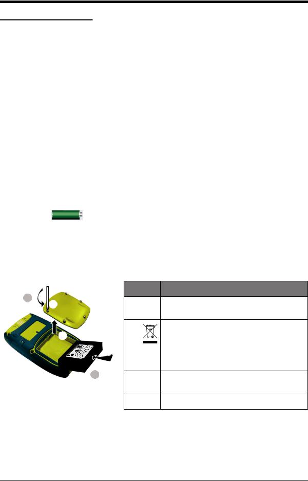
2.5.2 Install the battery
|
|
Step |
Procedure |
1 |
|
1. |
When the power is off, loosen the five screws (a) |
a |
|
||
|
|
|
and remove the cover (b). |
|
|
|
If necessary, turn the instrument over and collect |
|
b |
|
the discharged battery. |
|
|
|
If the battery does not hold a charge, discard it |
|
|
|
safely. Obey all the local health and safety |
|
|
|
procedures. |
|
2 |
2. |
Install the new fully-charged battery in the |
|
|
||
|
|
|
compartment. |
|
|
3. |
Refit the cover. |
2-2 Prepare the instrument |
K0460 - [EN] English |
Issue 1
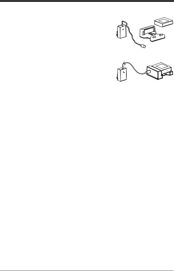
2.5.3 Charge the battery
2.5.4 Charge times
Fully-charge the battery, using the charger and cradle, in a safe area.
•The battery pack [a] (part number: IO620IS – Battery) will be partly-charged, it is recommended to fully charge the battery pack before using the instrument:
•Connect the charger [b] (part number: IO620IS-Charger) to a power supply.
[a]
[b]
[c]
 [d]
[d]
•Connect the charger to the cradle [c] (part number: IO620IS-Cradle).
•Correctly insert the battery into the cradle (making sure the battery pack label faces upwards).
•The battery charger LED [d] indicates the different charge states. When the LED shows green the battery pack is fully-charged and ready to use. The battery pack takes approximately 8 hours to fully charge.
Charge method |
Charge time (to full capacity) |
|
|
External battery charger |
≈ 6.5 hours |
|
|
During the charge cycle the charger LED indicator changes colour:
LED Indicator |
Mode |
|
|
Yellow |
Battery not connected |
|
|
Yellow |
Battery initialisation and analysis |
|
|
Orange |
Fast charge |
|
|
Green with intermittent yellow |
Top-off charge |
flash |
|
|
|
Green |
Trickle charge |
|
|
Alternating orange - green |
Error |
|
|
[EN] English - K0460 |
Prepare the instrument 2-3 |
Issue 1
2.5.5 Operating time
Operation |
Battery duration |
|
|
Continuous operation (measure) |
> 10 hours |
|
|
Continuous operation (measure and |
> 6 hours |
source with loop power on) |
|
|
|
Power save options
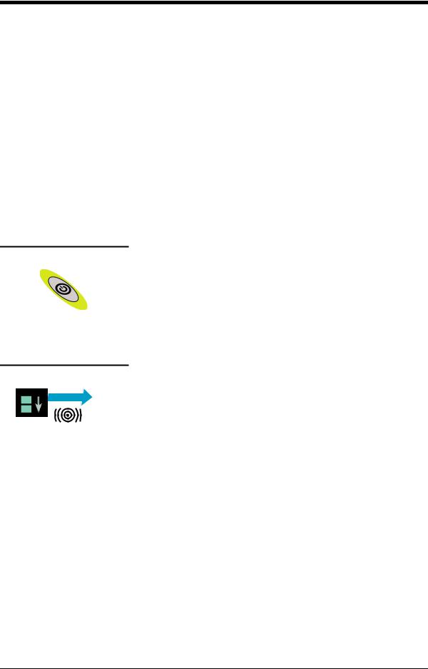
2.6Power on or off
2.7Display operation
TAP
These are typical operating times for a new, fully-charged Ni-MH battery pack with these settings:
•Backlight Intensity set to 80% (Default: 80%).
•Backlight Timeout set to 2 hours (Default: 2 minutes).
To get the best battery duration, set a low value for the
Backlight Intensity (40%) and a short Timeout; see Section 2.8.1 (Procedure to set the basic operations:).
To set the instrument power on, press and hold this button down until the display comes on (≈ 2 seconds). During the power on sequence, the instrument shows a timer and then shows the applicable data.
To set the instrument power off, press and hold this button. When the power is off, the last set of configuration options stays in memory.
This instrument has a touch-screen. To make a selection, lightly tap on the applicable display area (window, button, option) with a finger.
Caution: To prevent damage to the display, do not use sharp objects on the touch-screen.
The number of windows shown on the display is set by the number of task selections and external modules enabled (maximum: 6); see Section 2.8.3 (Procedures to make Task selections).
2-4 Prepare the instrument |
K0460 - [EN] English |

Issue 1
2.7.1 Change items in a list
B |
To change an item in a list, you have these options: |
|
|
|
|
A |
• |
tap on the item you want to use A . |
C |
||
|
• |
tap on the ▲ or ▼ button B . |
|
• |
tap on one of the horizontal bars beside the list C |
|
|
(if applicable). |
Accept: To accept the selection and go back to the previous display, tap this button. If necessary, tap this button on all subsequent displays until you get back to the start.
Cancel: To cancel the selection and go back to the previous display, tap this button
2.7.2 Change numeric values
There are numeric key-pad displays for these items:
•
•
•
•
dates and times
set-point values
source Automation processes (Nudge, Span Check, ... )
calibration and other processes
Tap in the necessary value on the key-pad. If applicable, the key-pad includes the buttons for +/- and decimal point.
Backspace: To go back one character, tap this button. If it is not a date or time, it deletes the character.
Accept: To accept the specified value and go back to the previous display, tap this button.
Cancel: To cancel the specified value and go back to the previous display, tap this button.
[EN] English - K0460 |
Prepare the instrument 2-5 |

Issue 1
2.7.3 Enter text
There are alphanumeric key-pad displays for these items:
2
•Captions; see Section 2.8.4 (maximum: 15 characters; all characters permitted)
•Filenames (maximum: 10 characters; no special characters)
1.Tap in the applicable characters.
2.To accept the data and go back to the previous display, tap on the completed text in the data entry box.
1
Next key-pad: To use characters on the next key-pad (upper case > lower case > numeric), tap this button.
Delete: To delete the last character in the data entry box, tap this button.
Escape: If there are no characters in the data entry box, the Esc button replaces the Del button. To leave the key-pad and go back to the previous display, tap on the Esc button.
2.7.4 Maximise/minimise a window
There can be up to 6 functions on the display. To set a Process (measure operations), an Automation option (source operations), or other Settings maximise the applicable function:
Processes (measure operations 
 )
)
Maximise Minimise
*1
Automation (source operations 
 )
)
2
*1
* Alternative options for step
TAP
2-6 Prepare the instrument |
K0460 - [EN] English |

Issue 1
2.8 Menu sequence
Section 2.8.1
Section 2.8.2
Chapter 6
†
Chapter 7
Section 2.10
†Normally, this is only necessary for versions with the Windows CE operating system, Touch Screen enables the screen to be calibrated and re-centred.
[EN] English - K0460 |
Prepare the instrument 2-7 |
Issue 1
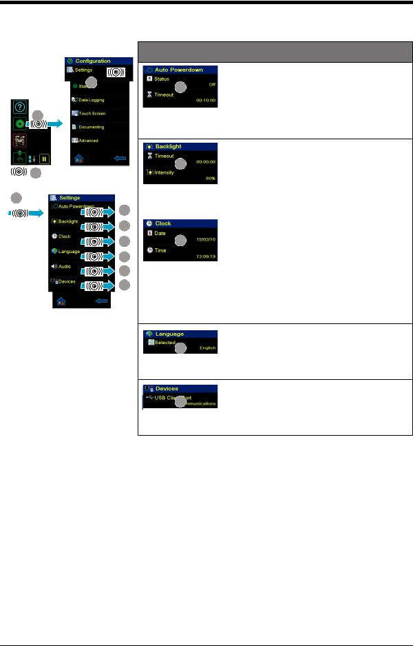
2.8.1 Procedure to set the basic operations:
Configuration
3
2
1
TAP
Settings
3
Description
|
Sets the power off automatically after the |
A |
specified Timeout period. To save the battery |
power, set this to On. |
Status: On or Off
Timeout: 00:02:00 to 01:00:00 hours:minutes:seconds (hh:mm:ss)
|
Sets the backlight. Low values save battery |
|
|
power; see Section 2.5.5 (Operating time). |
|
|
B |
|
|
Timeout: 00:02:00 to 02:00:00 hours:minutes:seconds (hh:mm:ss) |
|
A |
Intensity: 20, 40, 60, 80, 100% |
|
|
||
B |
Sets the date and time. The calibration function |
|
uses this to give calibration messages. |
||
|
||
C |
C |
D
EDate: day/month/year (dd/mm/yy) OR month/day/year (mm/dd/yy).
FThe format is factory configured. Time: 24 hour; hours:minutes:seconds (hh:mm:ss)
Sets the language.
D
Selected: English (Other languages to be released).
Sets the communications using the USB port.
F
Communications: Storage device, communications, active sync.
2-8 Prepare the instrument |
K0460 - [EN] English |
Loading...