


User Manual |
Druck DPI 620G-IS |
GE DigitalSolutions
Druck DPI620 Genii
Intrinsically Safe Calibrator
and Communicator Series
User Manual – 116M5464
© 2016 General Electric Company. All Rights Reserved. Specifications are subject to change without notice. GE is a registered trademark of General Electric Company. Other company or product names mentioned in this document may be trademarks or registered trademarks of their respective companies, which are not affiliated with GE

User Manual |
Druck DPI620G-IS |
Contents
1 Overview |
................................................................................................................. |
10 |
|
1.1 |
Equipment in the Box...................................................................................... |
10 |
|
1.2 |
Optional ................................................................................................Items |
11 |
|
1.3 |
Observance ....................................................................of the User Manual |
11 |
|
1.4 |
Safety .............................................................................................................. |
12 |
|
|
..................................................................... |
General Safety Precautions |
12 |
|
................................................. |
Operation in a Hazardous Environment |
13 |
|
................................................................................... |
General Warnings |
15 |
|
.................................................................................. |
Electrical warnings |
16 |
|
.................................................................................. |
Pressure Warnings |
18 |
1.5 |
Preparing ...............................................................................the Instrument |
19 |
|
1.6 |
Battery ...........................................................................................& Charger |
20 |
|
|
............................................................................... |
Charging the Battery |
20 |
|
............................................................................... |
Installing the Battery |
22 |
1.7 |
Power ..................................................................................................On/Off |
23 |
|
|
................................................................................................ |
Power On |
23 |
|
................................................................................................ |
Power Off |
24 |
|
................................................................ |
Power up from Standby Mode |
24 |
1.8 |
Operation ........................................................................................................ |
25 |
|
|
............................................................................. |
Dashboard Navigation |
25 |
|
................................................................. |
Set Date, Time and Language |
26 |
|
.................................................................................................... |
Themes |
26 |
|
......................................................................... |
DPI620G IS User Manual |
26 |
|
.............................................................................. |
Connection Diagrams |
26 |
22 Feb 2017 |
116M5464 Revision A |
Page 2 of 248 |
|

User Manual |
|
Druck DPI620G-IS |
|
|
|
Alarm Status............................................................................................ |
27 |
|
|
Operating Modes .................................................................................... |
28 |
1.9 |
Software and Firmware Upgrades .................................................................. |
29 |
|
|
|
Viewing Software Revision...................................................................... |
29 |
|
|
Upgrading the Unit Software .................................................................. |
29 |
|
|
Upgrading the HART Device Library........................................................ |
31 |
1.10 |
Maintenance ................................................................................................... |
33 |
|
|
|
Cleaning................................................................................................... |
33 |
1.11 |
Instrument Return .......................................................................................... |
34 |
|
|
|
Returned Material Procedure for USA.................................................... |
34 |
|
|
Returned Goods Procedure for Europe .................................................. |
35 |
|
|
Instrument Disposal in the European Union........................................... |
36 |
1.12 Packaging for Storage or Transportation........................................................ |
37 |
||
|
|
Environment............................................................................................ |
37 |
1.13 |
Marks and Symbols ......................................................................................... |
37 |
|
2 Electrical Operations............................................................................................... |
38 |
||
2.1 |
Measure & Source Functions.......................................................................... |
38 |
|
2.2 |
Basic Calibrator Operation.............................................................................. |
39 |
|
|
|
Saving Tasks ............................................................................................ |
39 |
|
|
Electrical Tasks ........................................................................................ |
40 |
|
|
Favourites................................................................................................ |
42 |
|
|
Custom Task............................................................................................ |
43 |
2.3 |
Function Utility Options .................................................................................. |
46 |
|
|
|
Max/Min ................................................................................................. |
46 |
|
|
Switch Test .............................................................................................. |
47 |
|
|
Relief Valve.............................................................................................. |
48 |
2.4 |
Measurement Display Options ....................................................................... |
50 |
|
22 Feb 2017 |
116M5464 Revision A |
Page 3 of 248 |
|

User Manual |
Druck DPI620G-IS |
|
2.5 |
Measure and Source Operations .................................................................... |
52 |
2.6 |
Example Procedure: Measure or Source Current ........................................... |
54 |
|
Example Procedure: Measure or Source Current, CH1........................... |
54 |
|
Example Procedure: Measure or Source Current, CH2........................... |
55 |
2.7Example Procedure: Measure or Source Current with Internal 15V Loop
Power, CH2 |
................................................................................................................. |
|
56 |
|
|
|
Example Procedure: Measure Current, Internal Loop Power, CH2 ........ |
57 |
|
|
|
Example Procedure: Source Current with Internal Loop Power, CH2 .... |
58 |
|
2.8 |
Example Procedure: Measure DC Voltage ...................................................... |
|
59 |
|
|
|
Example Procedure: Measure DC Voltage, CH1 ..................................... |
|
59 |
|
..................................... |
Example Procedure: Measure DC Voltage, CH2 |
|
60 |
2.9 |
Example .................................................Procedure: Source DC Voltage, CH1 |
|
61 |
|
2.10 |
Example .........................Procedures: Measure or Source Frequency Signals |
|
62 |
|
|
................................... |
Example Procedure: Measure Frequency Signals |
|
62 |
|
...................................... |
Example Procedure: Source Frequency Signals |
|
63 |
2.11 |
Example ..................................................Procedure: Measure/Simulate RTD |
|
64 |
|
|
............ |
Example Procedure: Measure/Simulate a RTD, 4 Wire Method |
64 |
|
|
............................ |
Example Procedure: Measure a RTD, 3 Wire Method |
|
66 |
|
............................ |
Example Procedure: Measure a RTD, 2 Wire Method |
|
67 |
2.12 |
Example ...................Procedure: Measure or Simulate a Thermocouple (TC) |
|
68 |
|
2.13 |
Example .....................................................................Procedure: Switch Test |
|
70 |
|
2.14 |
Error ..............................................................................................Indications |
|
73 |
|
3 Pressure ...............................................................Indicator Operation (MC620 IS) |
|
74 |
||
3.1 |
Parts .........................................................................................and Assembly |
|
75 |
|
|
............................................................................. |
Assembly Instructions |
|
77 |
3.2 |
Pressure .....................................................................................Connections |
|
78 |
|
|
............................................ |
Procedure (Attaching External Equipment) |
|
78 |
22 Feb 2017 |
116M5464 Revision A |
Page 4 of 248 |
||

User Manual |
|
Druck DPI620G-IS |
||
|
3.3 |
Procedure Overview |
....................................................................................... |
80 |
|
3.4 |
Set up a Leak Test ........................................................................................... |
|
83 |
|
3.5 |
Set the Pressure Module ....................................................................to Zero |
85 |
|
|
3.6 |
Error Indications.............................................................................................. |
|
86 |
4 |
Data Logging Operation .......................................................................................... |
|
87 |
|
|
4.1 |
Set up.............................................................................................................. |
|
89 |
|
4.2 |
Operation ........................................................................................................ |
|
91 |
|
4.3 |
File Review ...................................................................................................... |
|
91 |
|
4.4 |
Chart View....................................................................................................... |
|
92 |
|
4.5 |
File Management ............................................................................................ |
|
93 |
|
|
Erase........................................................................................................ |
|
93 |
|
|
Memory Status........................................................................................ |
|
93 |
|
|
Download Files........................................................................................ |
|
94 |
|
4.6 |
Data Format .................................................................................................... |
|
95 |
5 |
Documentation ....................................................................................................... |
|
96 |
|
|
5.1 |
Analysis ........................................................................................................... |
|
96 |
|
5.2 |
Set up.............................................................................................................. |
|
98 |
|
|
Define the Reference ................................................................Channel |
99 |
|
|
|
Define each Input ....................................................................Channel |
100 |
|
|
5.3 |
Analysis Function .......................................................................................... |
|
102 |
|
5.4 |
Run Procedure .............................................................................................. |
|
103 |
|
|
Sequence to Upload ...............................................and Download File |
104 |
|
6 |
HART® Operations................................................................................................. |
|
105 |
|
|
6.1 |
HART® Menu Operations .............................................................................. |
105 |
|
|
6.2 |
Start up ......................................................................................................... |
|
106 |
|
6.3 |
HART® Connections....................................................................................... |
|
107 |
|
6.4 |
Power Supply from the ................................................................Calibrator |
107 |
|
22 Feb 2017 |
116M5464 Revision A |
Page 5 of 248 |
||
User Manual |
|
Druck DPI620G-IS |
||
|
6.5 |
External Loop Power |
..................................................................................... |
108 |
|
6.6 |
Communicator Attached to a Network......................................................... |
109 |
|
|
6.7 |
Use of Test Connections ............................................................................... |
110 |
|
|
6.8 |
Viewing Primary Variables ............................................................................ |
111 |
|
|
|
Device Polling........................................................................................ |
|
112 |
|
|
Viewing HART® ...............................................................Configuration |
114 |
|
|
6.9 |
Start HART® SDC Application ........................................................................ |
115 |
|
|
6.10 |
HART® Toolbar .............................................................................................. |
|
117 |
|
6.11 |
Data Display .................................................................................................. |
|
118 |
|
6.12 |
Editing Values................................................................................................ |
|
119 |
|
6.13 |
Executing Methods ....................................................................................... |
|
121 |
|
|
Method Example ..................................................................Self test |
122 |
|
|
|
Method Example ............................................................Analog Trim |
123 |
|
|
6.14 |
Preferences ................................................................................................... |
|
125 |
|
6.15 |
Failed to find Device ..................................................................................... |
|
126 |
7 |
HART® Offline........................................................................................................ |
|
127 |
|
|
7.1 |
Introduction .................................................................................................. |
|
127 |
|
7.2 |
Start up ......................................................................................................... |
|
127 |
|
7.3 |
Start HART® Offline ....................................................................................... |
|
128 |
|
7.4 |
Create an Offline Configuration.................................................................... |
130 |
|
|
7.5 |
Browse an Offline Configuration................................................................... |
131 |
|
|
7.6 |
Edit an Offline Configuration ........................................................................ |
132 |
|
|
7.7 |
Saving the Configuration............................................................................... |
133 |
|
|
7.8 |
Uploading the Configuration ........................................................................ |
134 |
|
|
7.9 |
Working with Saved Configurations ............................................................. |
134 |
|
|
7.10 |
Delete HART Configuration........................................................................... |
134 |
|
8 |
Foundation™ Fieldbus........................................................................................... |
|
135 |
|
22 Feb 2017 |
116M5464 Revision A |
Page 6 of 248 |
||

User Manual |
|
Druck DPI620G-IS |
||
8.1 |
Introduction .................................................................................................. |
|
135 |
|
8.2 |
FOUNDATION Fieldbus Configurations......................................................... |
|
135 |
|
8.3 |
Start up.......................................................................................................... |
|
136 |
|
|
|
FOUNDATION™ Fieldbus Connections.................................................. |
|
138 |
8.4 |
FOUNDATION™ Fieldbus Application – Connecting to a Network ............... |
142 |
||
|
|
FOUNDATION™ Fieldbus Toolbar ......................................................... |
|
143 |
|
|
Scanning For Devices ............................................................................ |
|
145 |
|
|
Context Sensitive Menu ........................................................................ |
|
148 |
|
|
Device State .......................................................................................... |
|
150 |
|
|
Troubleshooting Connection Problems ................................................ |
|
154 |
8.5 |
FOUNDATION™ Fieldbus Application – Communication.............................. |
|
155 |
|
|
|
Device Focus View................................................................................. |
|
155 |
|
|
Block Navigation Tree ........................................................................... |
|
158 |
|
|
Block Header Bar................................................................................... |
|
160 |
|
|
Folder Variables .................................................................................... |
|
162 |
|
|
Displaying Parameter Help.................................................................... |
|
164 |
|
|
Refreshing Data..................................................................................... |
|
165 |
|
|
Editing Variables ................................................................................... |
|
166 |
|
|
Methods................................................................................................ |
|
168 |
8.6 |
FOUNDATION™ Fieldbus Application My Block.......................................... |
|
169 |
|
8.7 |
FOUNDATION Fieldbus Application Exporting Variables............................ |
|
171 |
|
|
|
Viewing Exported Variables in Channel Window.................................. |
|
172 |
8.8 |
Application Settings ...................................................................................... |
|
173 |
|
|
|
Device Library........................................................................................ |
|
173 |
|
|
Options.................................................................................................. |
|
173 |
|
|
Advanced .............................................................................................. |
|
174 |
8.9 |
Function Finder ............................................................................................. |
|
175 |
|
22 Feb 2017 |
116M5464 Revision A |
Page 7 of 248 |
||

User Manual |
|
Druck DPI620G-IS |
|
9 PROFIBUS PA Fieldbus .......................................................................................... |
177 |
||
9.1 |
Introduction .................................................................................................. |
177 |
|
9.2 |
PROFIBUS Configurations.............................................................................. |
177 |
|
9.3 |
Start up ......................................................................................................... |
178 |
|
|
|
PROFIBUS Connections ......................................................................... |
180 |
9.4 |
PROFIBUS Application – Connecting to a Network....................................... |
184 |
|
|
|
PROFIBUS Toolbar................................................................................. |
185 |
|
|
Scanning For Devices ............................................................................ |
187 |
|
|
Context Sensitive Menu ........................................................................ |
190 |
|
|
Troubleshooting Connection Problems ................................................ |
192 |
9.5 |
PROFIBUS Application – Communication ..................................................... |
193 |
|
|
|
Device Focus View................................................................................. |
193 |
|
|
Block Navigation Tree ........................................................................... |
196 |
|
|
Block Header Bar................................................................................... |
198 |
|
|
Folder Variables .................................................................................... |
200 |
|
|
Displaying Parameter Help.................................................................... |
202 |
|
|
Refreshing Data..................................................................................... |
203 |
|
|
Editing Variables ................................................................................... |
204 |
9.6 |
PROFIBUS Application My Block ................................................................. |
206 |
|
9.7 |
PROFIBUS Application Exporting Variables................................................. |
208 |
|
|
|
Viewing Exported Variables in Channel Window.................................. |
209 |
9.8 |
Application Settings ...................................................................................... |
210 |
|
|
|
Device Library........................................................................................ |
210 |
|
|
Options.................................................................................................. |
210 |
|
|
Advanced .............................................................................................. |
211 |
9.9 |
Function Finder ............................................................................................. |
212 |
|
10 |
Calibration Procedures ..................................................................................... |
214 |
|
22 Feb 2017 |
116M5464 Revision A |
Page 8 of 248 |
|
User Manual |
Druck DPI620G-IS |
|||
10.1 |
|
Before Starting .............................................................................................. |
|
214 |
10.2 |
|
Selection Sequence ....................................................................................... |
|
217 |
10.3 |
|
Calibration Procedures (CH1/CH2): Current (measure)................................ |
|
218 |
10.4 |
|
Calibration Procedures (CH1/CH2): Current (source)................................... |
|
220 |
10.5 |
|
Calibration Procedures (CH1/CH2): DC mV/Volts (measure) ....................... |
|
221 |
10.6 |
|
Calibration Procedures (CH1): DC mV/Volts (source)................................... |
|
223 |
10.7 |
|
Calibration Procedures (CH1): Frequency (measure/source)....................... |
|
225 |
10.8 |
|
Calibration Procedure (CH1): Frequency, Pulse Amplitude (source)............ |
229 |
|
10.9 |
|
Calibration Procedure (CH1): Resistance (measure) (standard)................... |
231 |
|
10.10 |
Calibration Procedure (CH1): Resistance (measure) (True Ohms) ........... |
233 |
||
10.11 |
Calibration Procedures (CH1): Resistance (source) .................................. |
|
234 |
|
10.12 |
Calibration Procedures (CH1): TC mV (measure)...................................... |
|
236 |
|
10.13 |
Calibration Procedures (CH1): TC mV (source) ......................................... |
|
238 |
|
10.14 |
Calibration Procedures (CH1): CJ and CJ (TC method) (measure) ........... |
239 |
||
10.15 |
Calibration Procedures: Pressure Indicator Modules (PM 620 IS) .......... |
242 |
||
11 |
General Specification ........................................................................................ |
|
244 |
|
11.1 |
|
Introduction .................................................................................................. |
|
244 |
12 |
Manufacturer.................................................................................................... |
|
247 |
|
13 |
Display Icons ..................................................................................................... |
|
248 |
|
22 Feb 2017 |
116M5464 Revision A |
Page 9 of 248 |
User Manual |
Druck DPI620G-IS |
1Overview
The Druck DPI 620 Genii Intrinsically Safe (DPI620G-IS) is a battery-powered instrument for use in a hazardous area. It is capable of electrical measure and source operations, HART®, Foundation Fieldbus and Profibus digital communications. It also supplies the power and user interface functions for all optional items. The touch-screen can display up to five different parameters simultaneously.
This version of the manual is applicable to software revisions DK420 V3.00 and above.
1.1Equipment in the Box
The following items are supplied with the DPI620G-IS :
•Mains Adaptor for battery charger (IO620-PSU)
•Battery Charger Cradle (IO620G-IS-CHARGER)
•Li-Ion battery pack (IO620G-IS-BATTERY)
•Set of six test leads
•Intrinsic Safety and Quick Start Guide
•Stylus
22 Feb 2017 |
116M5464 Revision A |
Page 10 of 248 |
User Manual |
Druck DPI620G-IS |
1.2Optional Items
The items that follow are optional items which can be used with the DPI620G-IS:
•Pressure Module Carrier, MC 620-IS: this attaches directly to the DPI620G-IS to make a fully integrated pressure instrument.
•Pressure Module, PM 620-IS: this attaches to the pressure module carrier (MC620-IS) or a Pressure Station (PV62X)-IS to enhance the pressure measurement functionality.
•Pressure Stations, PV 62X-IS: if the DPI620G-IS is installed in a Pressure Station, it becomes a fully integrated pressure calibrator.
1.3Observance of the User Manual
This manual contains safety and battery installation information for the DPI620G-IS. It is the responsibility of the customer, to make sure that all personnel operating and maintaining the equipment are correctly trained and qualified. Before operating or using the equipment read and obey all sections, including all WARNINGS and CAUTIONS given in the sections below and in the Quick Start Guide.
22 Feb 2017 |
116M5464 Revision A |
Page 11 of 248 |

User Manual |
Druck DPI620G-IS |
1.4Safety
General Safety Precautions
Read and obey all the operator's local Health and Safety regulations and Safe Working Procedures or Practices. When performing a procedure or task:
•Use only the approved tools, consumable materials and spares to operate and maintain the equipment.
•Read and obey all applicable WARNING signs.
•Make sure that:
All work areas are clean and clear of unwanted tools, equipment and materials.
All unwanted consumable materials are discarded in accordance with local health and safety and environmental regulations.
22 Feb 2017 |
116M5464 Revision A |
Page 12 of 248 |

User Manual |
Druck DPI620G-IS |
Operation in a Hazardous Environment
The DPI620G-IS can be operated in a Hazardous Area, subject to the restrictions specified in its classification:
 II 1 G
Ex ib IIC T4 Gb (-10°C ≤ Ta ≤ +50°C).
For full details, refer to the ‘Intrinsic Safety and Quick Start’ guide.
Use only Druck battery pack part number IO620G-IS- BATTERY.
Special Conditions for Safe Use
1.The DPI620G-IS USB Client Connection must be
connected to apparatus within a Safe Area with Um = 254V.
2.When a remote sensor is powered using the Channel 2,
15V, Uo loop supply, the remote sensor must be disconnected from all other sources of power
3.The Channel 2, V terminals can be connected to a FISCO system if the power for the system is provided from the
DPI620G-IS Channel 2, 15V, Uo loop supply and the electrical parameters of the field devices are compatible with those of the DPI620G-IS.
4.The DPI620G-IS should not be connected to a powered FISCO system unless its defined electrical parameters are compatible with the DPI620G-IS
22 Feb 2017 |
116M5464 Revision A |
Page 13 of 248 |
User Manual |
Druck DPI620G-IS |
5.The re-chargeable battery pack must be removed from the DPI620G-IS for recharging in a Safe Area using only
the charging contacts and the GE charger with Um = 254V. No connections must be made to the IS outputs.
6.The re-chargeable battery pack may be removed from, or replaced in, a DPI620G-IS within a Hazardous Area.
7.The ambient temperature is restricted to between -10°C and +50°C.
8.Both the MC620-IS Dual Pressure Module Carrier and the PV62X-IS Series Pressure Station have locations for one or two Pressure Modules to be screwed in. Before connection of the MC620-IS or PV62X-IS to the DPI620GIS, a PM620-IS Pressure Module or a protection cap (Part No. 191-369) must be screwed into any vacant location, and must remain in position until the assembly is removed from the DPI620G-IS.
9.The lower ambient temperature is limited to -10°C.
22 Feb 2017 |
116M5464 Revision A |
Page 14 of 248 |

User Manual |
Druck DPI620G-IS |
General Warnings
•Do not use tools on the instrument that might cause incendive sparks – this could cause an explosion if used in a Hazardous Area.
•Provide additional protection for equipment that may be damaged in service.
•It is dangerous to ignore the specified limits for the instrument or its related accessories. This can cause injuries.
•Use equipment only for the purpose for which it is provided.
•If the equipment is used in a manner not specified by the manufacturer, the protection provided by the equipment may be impaired.
•Make sure all equipment is serviceable.
•Wear all applicable Personal Protective Equipment (PPE).
•Do not use sharp objects on the touch-screen.
22 Feb 2017 |
116M5464 Revision A |
Page 15 of 248 |

User Manual |
Druck DPI620G-IS |
Electrical warnings
•To prevent electrical shocks or damage to the instrument, do not connect more than 30V CAT I between the terminals, or between the terminals and the ground (earth). Any connection must be compliant with the terminal input/output parameters.
•External circuits should have appropriate insulation to the mains.
•This instrument uses a Lithium-Ion (Li-Ion) battery pack. To prevent an explosion or fire, do not short circuit, do not disassemble, and keep safe from damage.
•To prevent an explosion or fire, use only the GE specified battery (IO620G-IS-BATTERY), power supply (Part: IO620PSU) and battery charger (Part: IO620G-IS-CHARGER).
•To prevent battery leakage or heat generation, only use:
-the battery charger (IO620G-IS-CHARGER ) and power supply IO620-PSU in the temperature range 0°C to 40°C (32°C to 104°F).
•The power supply IO620-PSU input range is 100 – 240Vac +/-10%, 50 to 60Hz, 250mA, installation category CAT II.
•Note that the operating and storage temperature range of the power supply (IO620-PSU) does not match that of the DPI620G-IS battery charger. (IO620-PSU operating temperature range 0°C to +40°C, storage temperature range -40°C to +70°C).
•Position the power supply so as not to obstruct the supply disconnecting device.
22 Feb 2017 |
116M5464 Revision A |
Page 16 of 248 |

User Manual |
Druck DPI620G-IS |
•The DC input to the DPI620G-IS battery charger is rated at 5V (+/-5%). Maximum current 2 Amps.
•Equipment is suitable for short-term and long-term TEMPORARY OVERVOLTAGES that may occur between the line conductor and earth in electrical installations.
•To make sure the display shows correct data, disconnect the test leads before power is set to on or changing to another measure or source function.
•Keep leads free from all contaminants.
The following summary of installation and measurement overvoltage categories are derived from IEC61010-1. The overvoltage categories indicate the severity of overvoltage transients
Overvoltage Description Category
Overvoltage category I has the least severe overvoltage transients. Generally CAT I
CAT I equipment is not designed to be directly connected to the mains supply. Examples of CAT I equipment are process loop powered devices
Overvoltage category II describes an electrical CAT II installation where typically single phase
equipment is connected. Examples of such equipment are appliances and portable tools.
22 Feb 2017 |
116M5464 Revision A |
Page 17 of 248 |

User Manual |
Druck DPI620G-IS |
Pressure Warnings
•Some liquid and gas mixtures are dangerous. This includes mixtures that occur because of contamination. Make sure that the equipment is safe to use with the necessary media.
•To prevent a dangerous release of pressure, isolate and bleed the system before disconnecting a pressure connection.
•To prevent a dangerous release of pressure, make sure that all the related pipes, hoses and equipment have the correct pressure rating, are safe to use and are correctly attached.
•To prevent damage to the DPI620G-IS, only use it within the specified pressure limits.
•Do not exceed the maximum pressures stated in the appropriate component manual for the unit under test.
•Reduce pressure at a controlled rate when venting to atmosphere.
•Carefully de-pressurize all pipes to atmospheric pressure before disconnecting and connecting to the unit under test.
•Observe cleanliness when using the instrument.
•Severe damage can be caused if equipment connected to this instrument is contaminated.
•Connect only clean equipment to the instrument. To avoid any contamination, an external filter is recommended.
22 Feb 2017 |
116M5464 Revision A |
Page 18 of 248 |
User Manual |
Druck DPI620G-IS |
1.5Preparing the Instrument
On receipt of the instrument check the contents in the box, listed in Section 1.1. It is recommended to retain the box and packaging for future use.
22 Feb 2017 |
116M5464 Revision A |
Page 19 of 248 |

User Manual |
Druck DPI620G-IS |
1.6Battery & Charger
Charging the Battery
With reference to Figure 1-1 Battery & Charger:
1.Connect the DC power supply/AC Adaptor to the +5V DC connection [1] on the side of the battery charger cradle.
2.Insert the battery [2] into the charger cradle at a slight angle, then push and click into place. Tighten the thumb screws [3] to prevent accidental disconnection.
3.Switch on the mains power supply.
3
2 
LED1
LED2
1
Figure 1-1 Battery & Charger
22 Feb 2017 |
116M5464 Revision A |
Page 20 of 248 |
User Manual |
Druck DPI620G-IS |
Battery Charge/Charger Status is shown by LED1, LED2 on the cradle (ref. Figure 1-1). Status definitions are shown in Figure 1-2.
LED1 LED2
Figure 1-2 Battery Charge/Charger Status
Battery charge time is approximately 8 hours.
Note: To reset charger in fault condition it may be necessary to disconnect power.
22 Feb 2017 |
116M5464 Revision A |
Page 21 of 248 |

User Manual |
Druck DPI620G-IS |
Installing the Battery
With reference to Figure 1-3:
1.Slide the battery [1] onto the underside of the instrument [2].
2.Tighten the thumbscrews [3].
3 
1
2 
Figure 1-3 Installing the Battery
22 Feb 2017 |
116M5464 Revision A |
Page 22 of 248 |
User Manual |
Druck DPI620G-IS |
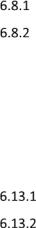
1.7Power On/Off
Power On
With reference to Figure 1-4: From OFF – momentarily press the power button [1] until the display GE logo appears.
NOTE: The GE Logo will appear briefly and then the display will go blank for a number of seconds while the instrument initialises.
Client USB
1 
Figure 1-4 DPI620G-IS Side View
22 Feb 2017 |
116M5464 Revision A |
Page 23 of 248 |

User Manual |
Druck DPI620G-IS |
Power Off
Press and Release the Power Button:
The POWERDOWN OPTIONS window will be displayed.
Figure 1-5 Power down Options
SWITCH OFF: Full power down of DPI620G-IS – recommended if the instrument is not going to be used for several hours (the instrument requires a full re-boot on next power up).
STANDBY: DPI620G-IS is placed in standby mode – reduced power consumption from operating mode – recommended if the instrument is to be inactive for short periods (the instrument has fast turn on from STANDBY mode).
Note: SWITCH OFF can also be achieved by pressing and holding the power button until the screen is blank.
Power up from Standby Mode
When powering up from standby mode the instrument always opens the last screen shown before it entered standby mode.
22 Feb 2017 |
116M5464 Revision A |
Page 24 of 248 |

User Manual |
Druck DPI620G-IS |
1.8Operation
Dashboard Navigation
The Dashboard is navigated by swiping a finger from top to bottom while touching the screen. Functions screens are navigated by swiping a finger from right to left while touching the screen.
Figure 1-6 Dashboard
Note: Fieldbus and Profibus are not installed on all units
22 Feb 2017 |
116M5464 Revision A |
Page 25 of 248 |

User Manual |
Druck DPI620G-IS |
Set Date, Time and Language
To access Date, Time and Language menus select:
DASHBOARD >> |
SETTINGS >> DATE |
|
>> TIME |
|
>> LANGUAGE |
Themes |
|
Two themes are available: Dark and Light; select the correct theme for the light level. Select:
DASHBOARD >> |
SETTINGS >> THEME |
DPI620G-IS User Manual
All the information required to operate the Druck DPI620GIS, is in the Help section of the Dashboard.
To access the User Manual::
DASHBOARD >> |
HELP >> MANUAL |
Connection Diagrams
Connection diagrams are included in the User manual and are also located at:
DASHBOARD >> HELP >> CONNECTIONS
22 Feb 2017 |
116M5464 Revision A |
Page 26 of 248 |
User Manual |
Druck DPI620G-IS |
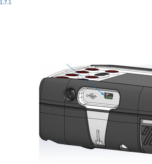
Alarm Status
An Alarm Status is indicated with a Red LED on the Status button in the DASHBOARD screen; and a Red LED on the Home button in other screens.
Figure 1-7 Alarm Indication
To View Alarms select:
DASHBOARD >>  STATUS >> ALARM STATE
Figure 1 8 Alarm State
Selecting the Alarm will clear the indication until the next power down.
22 Feb 2017 |
116M5464 Revision A |
Page 27 of 248 |

User Manual |
Druck DPI620G-IS |
Operating Modes
The DPI620G-IS can be used as follows:
•Calibrator (with independent functions on each of five channels).
-Data logging capabilities
-Documenting capabilities
•HART® Communicator.
•Foundation Fieldbus Communicator.
•Profibus Communicator.
22 Feb 2017 |
116M5464 Revision A |
Page 28 of 248 |

User Manual |
Druck DPI620G-IS |
1.9Software and Firmware Upgrades
Viewing Software Revision
The software revisions running on the DPI620G-IS can be viewed by selecting:
DASHBOARD >>  STATUS >> SOFTWARE BUILD
Note: If the software revision number is highlighted red then an upgrade is available.
Upgrading the Unit Software
1.Go to the website www.gemeasurement.com
The website contains .zip files for upgrading the Operating System (OS), Application, HART, and CH1 FPGA software. The software packages may be contained in one .zip file or may be in individual .zip files.
2.Follow the website instructions to download the .zip file(s) onto a PC local hard drive.
3.At the DPI620G-IS:
Select:
DASHBOARD >>  DEVICES >> USB CLIENT PORT
Select ‘Storage Device’ & return to the DASHBOARD
22 Feb 2017 |
116M5464 Revision A |
Page 29 of 248 |

User Manual |
Druck DPI620G-IS |
4.Connect the DPI620G-IS Client USB port to the PC (Ref: Figure 1-4).
A removable disk drive (for example ‘F:’) should appear at the PC, containing a folder named ‘Install’ at the root level (e.g. F:\Install).
5.At the PC:
If the removable drive does not include the ‘install’ folder, create one at the root level (e.g. F:\Install).
Navigate to the downloaded .zip file(s).
For each .zip file, extract the contents to the removable drive ‘Install’:
(right click .zip file >> select ‘Extract All’ >> follow the on-screen instructions)
6.When extraction is complete, remove the USB lead (otherwise the instrument will not upgrade).
NOTE: at the PC perform “Safely Remove Hardware and Eject Media” before removing the USB lead.
7.At the DPI620G-IS:
Select:
DASHBOARD >> |
ADVANCED |
Enter the S/W upgrade PIN: 5487
Select the required S/W upgrade
Follow the on-screen instructions
8.On completion of S/W upgrade(s), switch the unit off and then on.
9.Check for successful upgrade by returning to the DASHBOARD and viewing the S/W revision.
22 Feb 2017 |
116M5464 Revision A |
Page 30 of 248 |
 Loading...