


DHDSR46EG8WW
GE DHDSR46EG8WW, GHDN520ED1WS, GLDP280ED0WS, GLDP280ED1WS, GLDS560ED0WW Installation Guide
...
Installation
Instructions
Electric Drger
04
Questions on Installation? Call: 800.GE.CARES (US)
or visit our web site at: www.GEAppliances.com (US)
BEFORE YOU BEGIN
Readtheseinstructionscompletelyandcarefully.
• IMPORTANT- savethese instructions
for local inspector's use.
• IMPORTANT- Observeall governing
codesand ordinances.
• Noteto Installer - Besureto leavethese
instructionswith the customer.
• Noteto Customer - Keeptheseinstructions
with your Owner'sManualforfuture reference.
• Beforethe old dryeris removedfrom serviceor
discarded,removethe dryerdoor.
• inspectthe dryerexhaustoutletandstraighten
the outlet wallsif they arebent.
• Serviceinformationand thewiring dia-gram
arelocatedin the controlconsole.
• Donot allowchildrenonor inthe appliance.
Closesupervisionofchildren isnecessarywhen
the applianceisused nearchildren.
• installthedryer wherethe temperature is
aboveSO°Ffor satisfactory operationof the
dryercontrol system.
• Product failure due to improper installation
isnot covered under the warranty.
NOTE:Installation and service of this dryer
requires basic mechanical and electrical
skills. It is gour responsibilitg to contact
a qualified installer to make the electrical
connections.
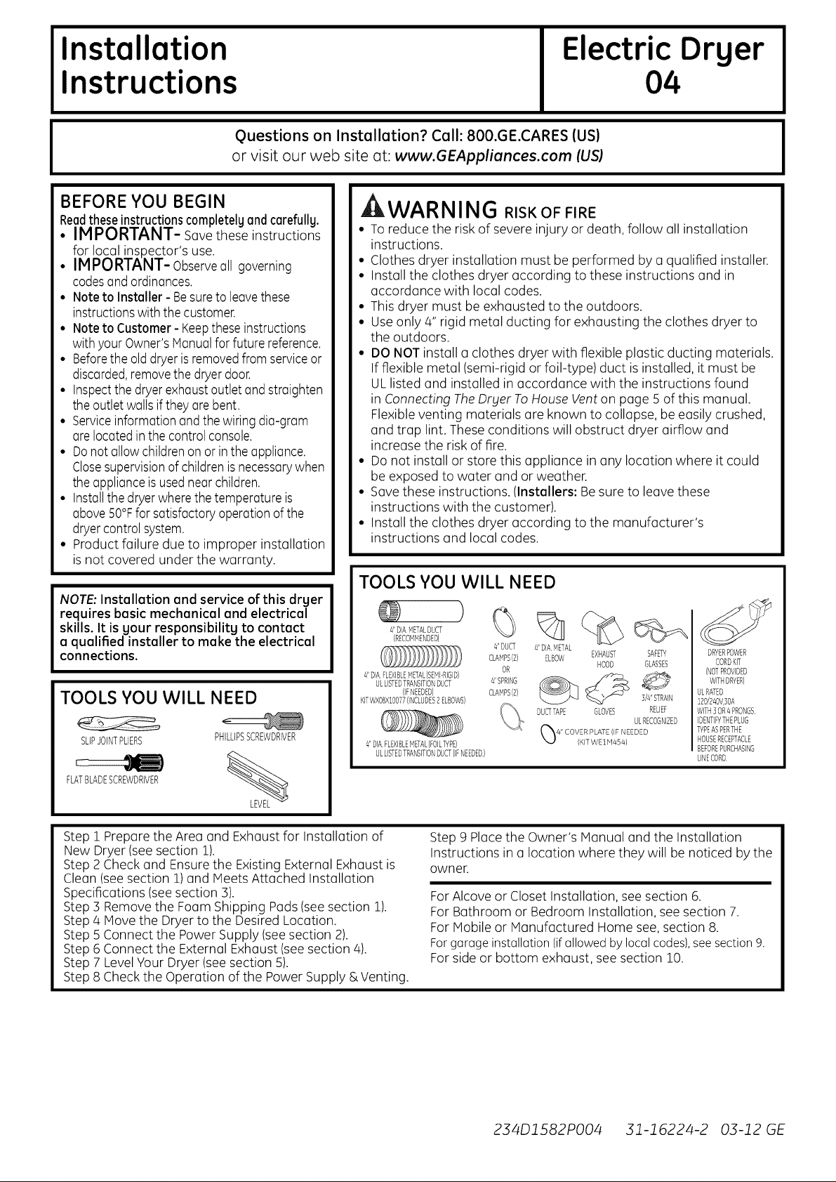
TOOLS YOU WILL NEED
SLIPJOINTPLIERS
FLATBLADESCREWDRIVER
PHILLIPSSCREWDRIVER
%
WARNING RISK OF FIRE
• Toreduce the riskof severe injury or death, follow all installation
instructions.
• Clothes dryer installation must be performed by a qualified installer.
• Install the clothes dryer according to these instructions and in
accordance with local codes.
• This dryer must be exhausted to the outdoors.
• Use only 4" rigid metal ducting for exhausting the clothes dryer to
the outdoors.
• DO NOT install a clothes dryer with flexible plastic ducting materials.
If flexible metal (semi-rigid or foil-type) duct is installed, it must be
ULlisted and installed in accordance with the instructions found
in Connecting TheDryer ToHouse Venton page 5 of this manual.
Flexible venting materials are known to collapse, be easily crushed,
and trap lint. These conditions will obstruct dryer airflow and
increase the risk of fire.
• Do not install or store this appliance in any location where it could
be exposed to water and or weather.
• Savethese instructions. (Installers: Besure to leave these
instructions with the customer).
• Install the clothes dryer according to the manufacturer's
instructions and local codes.
TOOLS YOU WILL NEED
)
41DIAMETALDUCT V/ll
(RECOMMENDED)
",,../..jj
# DUCT # DIA _v_ETAL
CLAMPS(2) ELBOW
OR
#SPRING
CLAMPS(2)
DUCTTAPE
41DIAFLEXIBLEMETAL(SEMDRIGID)
ULLISTEDTRANSITIONDUCT
(IFNEEDED)
KFWXBBXlOB77)INCLUDES2ELBOWS)
4'DIAFLEXIBLEMETAL(FOILTYPE)
ULLISTEDTRANSITIONDUCT(IFNEEDED)
EXHAUST
HOOD
GLOVES
SAFETY
GLASSES
]/#'STRAIN
RELIEF
ULRECOGNIZED
DRYERPOWER
CORDKIT
(NOTPROVIDED
WITHDRYER)
ULRATED
1BO/24OV]OA
WITH3OR4 PRONGS
IDENTIFYTHEPLUG
TYPEASPERTHE
HOUSERECEPTACLE
BEFOREPURCHASING
LINECORD
Step 1 Prepare the Area and Exhaust for Installation of
New Dryer (seesection 1).
Step 2 Check and Ensurethe Existing External Exhaust is
Clean (see section 1) and Meets Attached Installation
Specifications (see section 3).
Step 3 Remove the Foam Shipping Pads(see section 1).
Step 4 Move the Dryer to the Desired Location.
Step 5 Connect the Power Supply (see section 2).
Step 6 Connect the External Exhaust (seesection 4).
Step 7 LevelYour Dryer (seesection 5).
Step 8 Check the Operation of the Power Supply & Venting.
Step 9 Place the Owner's Manual and the Installation
Instructions in a location where they will be noticed by the
owner.
For Alcove or Closet Installation, see section 6.
For Bathroom or Bedroom Installation, see section 7.
For Mobile or Manufactured Home see, section 8.
For garage installation (if allowed by local codes), see section 9.
For side or bottom exhaust, see section 10.
234D1582PO04 31-16224-2 03-12 GE
Installation Instructions
Minimum Clearance Other Than Alcove or Closet Installation
Minimum clearance to combustible surfaces and for air opening are: 0 in. clearance both sides and ] in. rear.
Consideration must be given to provide adequate clearance for installation and service.
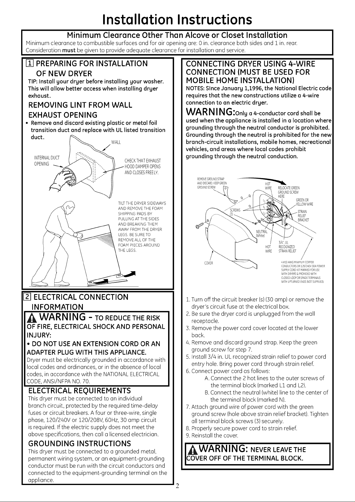
m PREPARING FOR INSTALLATION
OF NEW DRYER
TIP:Install your dryer before installing your washer.
This will allow better accesswhen installing dryer
exhaust.
REMOVING LINT FROM WALL
EXHAUST OPENING
• Remove and discard existing plastic or metal foil
transition duct and replace with UL listed transition
duct.
WALL
/
INTERNALDUCT
CHECKTHATEXHAUST
OPENING i- HOODDAHPEROPENS
ANDCLOSESFREEL?.
TILTTHE DRYERSIDEWAYS
AND REMOVETHE FOAM
SHIPPING PADS BY
PULLING ATTHE SIDES
AND BREAKINGTHEM
AWAY FROM THE DRYER
LEGS. BE SURE TO
REMOVEALL OF THE
FOAM PIECESAROUND
THE LEGS.
Izl ELECTRICAL CONNECTION
INFORMATION
WARNING - TOREDUCETHERISK
OF FIRE, ELECTRICAL SHOCK AND PERSONAL
INJURY:
• DO NOT USE AN EXTENSION CORD OR AN
ADAPTER PLUG WITH THIS APPLIANCE.
Dryer must be electrically grounded in accordance with
local codes and ordinances, or in the absence of local
codes, in accordance with the NATIONALELECTRICAL
CODE,ANSI/NFPANO.70.
ELECTRICAL REQUIREMENTS
This dryer must be connected to an individual
branch circuit, protected by the required time-delay
fuses or circuit breakers. A four or three-wire, single
phase, 120/240V or 120/208V, 60Hz, 30 amp circuit
is required. If the electric supply does not meet the
above specifications, then call a licensed electrician.
GROUNDING INSTRUCTIONS
This dryer must be connected to a grounded metal,
permanent wiring system, or an equipment-grounding
conductor must be run with the circuit conductors and
connected to the equipment-grounding terminal on the
appliance.
CONNECTING DRYER USING 4-WIRE
CONNECTION (MUST BE USED FOR
MOBILE HOME INSTALLATION)
NOTES:Since Jonuarg 1,1996, the National Electric code
requires that the new constructions utilize a 4-wire
connection to an electric dryer.
WARNING:onlua4-conductor cord shall be
used when the appliance is installed in a location where
grounding through the neutral conductor is prohibited.
Grounding through the neutral is prohibited for the new
branch-circuit installations, mobile homes, recreational
vehicles, and areas where local codes prohibit
grounding through the neutral conduction.
REHOVEGROUNDSTRAP
ANDDISCARDKEEPGREEN
GROUNDSCREW_" 7 WIRE RELOCATEGREEN
GROUNDSCREW
"4. _ HERE GREENOR
RELIEF
BRACKET
COVER
HOT
WIRE
3/4",UL
RECOGNIZED
STRAINRELIEF
4#10 AWGHINIHUH COPPER
CONDUCTORSOR120/240V 50APOWER
SUPPLYCORDKITHARKEDFORUSE
WITHDRYERS& PROVIDEDWITH
CLOSEDLOOPORSPADETERMINALS
WiTH UPTURNEDENDS(NOTSUPPLIED)
1.Turn off the circuit breaker (s)(30 amp) or remove the
dryer's circuit fuse at the electrical box.
2.Be sure the dryer cord is unplugged from the wall
receptacle.
3.Remove the power cord cover located at the lower
back.
4.Remove and discard ground strap. Keep the green
ground screw for step 7.
5.Install 3/4 in. ULrecognized strain relief to power cord
entry hole. Bring power cord through strain relief.
6.Connect power cord as follows:
A.Connect the 2 hot lines to the outer screws of
the terminal block (marked L1and L2).
B.Connect the neutral (white) line to the center of
the terminal block (marked N).
7.Attach ground wire of power cord with the green
ground screw (hole above strain relief bracket). Tighten
all terminal block screws (3)securely.
8.Properly secure power cord to strain relief.
9.Reinstall the cover.
WARNING: NEVER LEAVE THE
COVER OFF OF THE TERMINAL BLOCK.
I
2
Installation Instructions
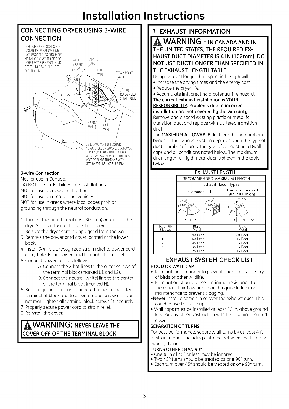
CONNECTING DRYER USING 3-WIRE
CONNECTION
iFREQUIRED,BYLOCALCODE,
INSTALLEXTERNALGROUND
(NOTPROVIDED)TOGROUNDED
METALCOLDWATERPiPEOR GREEN GROUND
OTHERESTABLISHEDGROUND GROUND STRAP
DETERMINEDBYAOUALIFIED SCREW
ELECTRICIAN. HOT
WIRE
q)
STRAINRELIEF
BRACKET
3/#',UL
RECOGNIZED
NEUTRAL
(White) HOT
WiRE
COVER
] #10 AWGMiNiMUMCOPPER
CONDUCTORSOR120/240V]0APOWER
SUPPLYCORDKITMARKEDFORUSE
WITHDRYERS&PROVIDEDWITHCLOSED
LOOPORSPADETERMINALSWITH
UPTURNEDENDS(NOTSUPPLIED).
3-wire Connection
Not for use in Canada.
DONOTuse for Mobile Home Installations.
NOTfor use on new construction.
NOTfor use on recreational vehicles.
NOTfor use in areas where local codes prohibit
grounding through the neutral conduction.
1.Turn off the circuit breaker(s) (30 amp) or remove the
dryer's circuit fuse at the electrical box.
2.Be sure the dryer cord is unplugged from the wall.
3. Remove the power cord cover located at the lower
back.
4. Install 3/4 in. ULrecognized strain relief to power cord
entry hole. Bring power cord through strain relief.
5.Connect power cord as follows:
A. Connect the 2 hot lines to the outer screws of
the terminal block (marked L1and L2).
B.Connect the neutral (white) line to the center
of the terminal block (marked N).
6.Be sure ground strap isconnected to neutral (center)
terminal of block and to green ground screw on cabi-
net rear.Tighten all terminal block screws (3)securely.
7.Properly secure power cord to strain relief.
8. Reinstall the cover.
I WARNING: NEVER LEAVE THE
COVER OFF OF THE TERMINAL BLOCK.
I
EXHAUST INFORMATION
WARNING -IN CANADAANDIN
THE UNITED STATES, THE REQUIRED EX-
HAUST DUCT DIAMETER IS 4 IN (102ram). DO
NOT USE DUCT LONGER THAN SPECIFIED IN
THE EXHAUST LENGTH TABLE.
Using exhaust longer than specified length will:
• Increase the drying times and the energy cost.
• Reducethe dryer life.
• Accumulate lint, creating a potential fire hazard.
The correct exhaust installation is YOUR
RESPONSIBILITY.Problems due to incorrect
installation are not covered by the warranty.
Remove and discard existing plastic or metal foil
transition duct and replace with ULlisted transition
duct.
The MAXIMUM ALLOWABLEduct length and number of
bends of the exhaust system depends upon the type of
duct, number of turns, the type of exhaust hood (wall
cap), and all conditions noted below. The maximum
duct length for rigid metal duct is shown in the table
below.
EXHAUST LENGTH
RECOMMENDED MAXIMUM LENGTH
Exhaust Hood Types
Recommended Use only for short
run installations
4" DIA.
4"I-- "-I I_21/2"
No.of 90° Rigid Rigid
Elbows Metal Metal
0 90 Feet 60 Feet
I 60 Feet 45 Feet
2 45 Feet 35 Feet
3 35 Feet 25 Feet
4 25 Feet 15 Feet
EXHAUST SYSTEM CHECK LIST
HOOD ORWALL CAP
• Terminate in a manner to prevent back drafts or entry
of birds or other wildlife.
• Termination should present minimal resistance to
the exhaust air flow and should require little or no
maintenance to prevent clogging.
•Never install a screen in or over the exhaust duct. This
could cause lint build up.
• Wall caps must be installed at least 12 in. above ground
level or any other obstruction with the opening pointed
down.
SEPARATIONOF TURNS
Forbest performance, separate allturns by at least 4 ft.
of straight duct, including distance between last turn and
exhaust hood.
TURNSOTHERTHAN 90°
• One turn of 45oor less may be ignored.
• Two 450turns should be treated as one 900turn.
• Eachturn over 450 should be treated as one 900turn.
3
 Loading...