

Page 1
5008
!!
!
Caution!
These Operating Instructions in pdfformat are for information only.
They are not a replacement for the
Operating Instructions supplied with
the machine/device and options.
Hemodialysis System
Operating Instructions
Software version: 3.52
Edition: 5/09.06
Part no.: M38 816 1
0123
Fresenius
Medical
Care
Page 2

Page 3

Table of Contents Page
1Index
2 Important Information
2.1 Important Information on the Operating Instructions............................................................ 2-1
2.2 Important Information on the System...................................................................................... 2-3
2.3 Addresses .................................................................................................................................. 2-8
3Design
3.1 Front View .................................................................................................................................. 3-1
3.2 Rear View ................................................................................................................................... 3-2
3.3 Lateral View, Left Side .............................................................................................................. 3-3
3.4 Lateral View, Right Side............................................................................................................ 3-4
3.5 Monitor Front ............................................................................................................................. 3-6
3.6 Monitor Rear .............................................................................................................................. 3-7
3.7 Extracorporeal Blood Module ..................................................................................................3-8
3.8 Extracorporeal Blood Module with Additional Functions ................................................... 3-12
3.9 Hydraulics ................................................................................................................................ 3-13
3.10 Hydraulics Connectors ........................................................................................................... 3-14
3.11 External Connection Options/Connection to Power Supply ............................................... 3-15
4 Graphical User Interface
4.1 After Turning Power on to the System .................................................................................... 4-1
4.2 Overview (Screen) ..................................................................................................................... 4-2
4.3 General Operation Philosophy.................................................................................................4-3
4.4 Examples for Data Entry (Treatment Data) ............................................................................. 4-7
4.5 Screen Saver.............................................................................................................................. 4-9
5 Preparation
5.1 Preparation using ONLINEplus™ ........................................................................................... 5-1
5.2 Preparation with Rinse Solution Bag .................................................................................... 5-17
5.3 Single-Needle (Option) Preparation Using ONLINEplus™ ................................................. 5-31
5.4 Single-Needle (Option) Preparation with Rinse Solution Bag............................................. 5-47
Fresenius Medical Care 5008 OP 5/09.06 iii
Page 4

Table of Contents Page
6 Treatment
6.1 TreatmentusingONLINEplus™ ................................................................................................. 6-1
6.2 Treatment (Prepared with Rinse Solution Bag) ...................................................................... 6-5
6.3 Single-Needle (Option) Treatment Using ONLINEplus™....................................................... 6-9
6.4 Single-Needle (Option) Treatment (Prepared with Rinse Solution Bag) ............................ 6-17
7 Reinfusion
7.1 Reinfusion using ONLINEplus™ .............................................................................................. 7-1
7.2 Reinfusion with Rinse Solution Bag ........................................................................................ 7-5
7.3 Single-Needle (Option) Reinfusion Using ONLINEplus™...................................................... 7-9
7.4 Single-Needle (Option) Reinfusion with Rinse Solution Bag ................................................ 7-9
8 Cleaning
8.1 Basic Requirements .................................................................................................................. 8-1
8.2 Connecting the Disinfectant Container ................................................................................... 8-2
8.3 Starting a Cleaning / Disinfection Program............................................................................. 8-3
8.4 Aborting a Cleaning / Disinfection Program ........................................................................... 8-4
8.5 Cleaning / Disinfection Program Complete............................................................................. 8-4
8.6 Checking for Residual Disinfectant ......................................................................................... 8-5
8.7 Surface Cleaning / Disinfection................................................................................................ 8-5
8.8 Turning the Hemodialysis System Off..................................................................................... 8-6
9 Alarm Processing
9.1 Messages (Information/Warning/Alarm).................................................................................. 9-1
9.2 Air Detected Below the Venous Bubble Catcher.................................................................... 9-2
9.3 Micro Bubbles Detected Below the Venous Bubble Catcher ................................................ 9-7
9.4 Management of Alarm Limits.................................................................................................. 9-14
9.5 Blood Leak ............................................................................................................................... 9-14
9.6 Conductivity ............................................................................................................................. 9-15
9.7 Manually Opening the Arterial Pressure Measurement Unit ............................................... 9-15
9.8 Power Failure (Outage) ........................................................................................................... 9-15
9.9 Screen Failure .......................................................................................................................... 9-17
iv Fresenius Medical Care 5008 OP 5/09.06
Page 5

Table of Contents Page
10 Other Functions
10.1 SYSTEM SCREEN Settings..................................................................................................... 10-1
10.2 Operator Setup ........................................................................................................................ 10-2
10.3 Emergency Button................................................................................................................. 10-26
10.4 Emptying / Changing the bibag
10.5 Changing the DIASAFE
10.6 Cleaning the Dialysate Particle Filter .................................................................................. 10-28
10.7 Collecting a Sample .............................................................................................................. 10-28
10.8 Removing Lines During Preparation ................................................................................... 10-28
10.9 Removing Lines During Treatment...................................................................................... 10-29
10.10 Circulation.............................................................................................................................. 10-30
10.11 Setting the Level in the Venous Bubble Catcher................................................................ 10-31
10.12 Single-Needle Click-Clack .................................................................................................... 10-32
®
plus ............................................................................................... 10-27
®
.......................................................................................... 10-26
11 System Description
11.1 Specifications .......................................................................................................................... 11-1
11.2 Storage ................................................................................................................................... 11-16
11.3 Transportation ....................................................................................................................... 11-16
11.4 Environmental Compatibility and Recycling ...................................................................... 11-17
11.5 System Description ............................................................................................................... 11-22
11.6 Blood Lines (Description)..................................................................................................... 11-34
11.7 Initial Start-Up ........................................................................................................................ 11-42
11.8 Technical Safety Checks and Technical Measurement Checks ....................................... 11-47
11.9 Definitions and Terms........................................................................................................... 11-52
11.10 Abbreviations......................................................................................................................... 11-53
11.11 Symbols.................................................................................................................................. 11-54
11.12 Consumables Symbols ......................................................................................................... 11-55
12 Consumables
12.1 To be Observed in Chapter Consumables ............................................................................ 12-1
12.2 Dialyzers................................................................................................................................... 12-1
12.3 Blood Lines .............................................................................................................................. 12-1
12.4 Disposable Syringes ............................................................................................................... 12-2
12.5 Hemodialysis Concentrates ...................................................................................................12-2
12.6 Dialysate Filter DIASAFE
Fresenius Medical Care 5008 OP 5/09.06 v
®
plus............................................................................................... 12-2
Page 6

Table of Contents Page
12.7 Surface Disinfection / Surface Cleaning................................................................................ 12-3
12.8 Disinfectants for the Hydraulics............................................................................................. 12-3
12.9 Disinfectant Indicators ............................................................................................................ 12-4
13 Certificates
13.1 EC Certificate ........................................................................................................................... 13-1
14 Appendix
14.1 Bibliography............................................................................................................................. 14-1
15 Option OCM (Online Clearance Monitoring)
15.1 To Be Observed Before Using the OCM ................................................................................ 15-1
15.2 Menu Overview ........................................................................................................................ 15-2
15.3 Checking/Setting the OCM Parameters ................................................................................. 15-3
15.4 Stability Criteria ....................................................................................................................... 15-4
15.5 Starting the OCM ..................................................................................................................... 15-4
15.6 Aborting the OCM .................................................................................................................... 15-4
15.7 Alarm Processing .................................................................................................................... 15-5
16 ONLINEplus™
16.1 Menu Overview ........................................................................................................................ 16-2
16.2 Preparation/Treatment/Reinfusion......................................................................................... 16-3
17 Option SN (Single-Needle)
17.1 Menu Overview ........................................................................................................................ 17-2
17.2 Preparation/Treatment/Reinfusion......................................................................................... 17-3
18 Option BPM (Blood Pressure Monitoring)
18.1 To Be Observed Before Using the BPM Option.................................................................... 18-1
18.2 Blood Pressure Cuffs / Pressure Tubing............................................................................... 18-1
18.3 Menu Overview ........................................................................................................................ 18-2
18.4 Applying the Blood Pressure Cuff ......................................................................................... 18-3
vi Fresenius Medical Care 5008 OP 5/09.06
Page 7

Table of Contents Page
18.5 Checking/Setting the Inflation Pressure/Alarm Limits......................................................... 18-3
18.6 Starting the Blood Pressure Measurement........................................................................... 18-4
18.7 Blood Pressure Measurement Completed ............................................................................ 18-4
18.8 Aborting the Blood Pressure Measurement ......................................................................... 18-5
18.9 Displaying Graphics and Blood Pressure History ............................................................... 18-5
19 Option CBPM
20 Option BTM (Blood Temperature Monitor)
20.1 To Be Observed Before Using the BTM Option.................................................................... 20-1
20.2 Menu Overview ........................................................................................................................ 20-2
20.3 Preparation............................................................................................................................... 20-3
20.4 Recirculation............................................................................................................................ 20-3
20.5 Temperature Control ............................................................................................................... 20-4
20.6 Displaying Graphics and BTM Events ................................................................................... 20-4
21 Option BVM (Blood Volume Monitor)
21.1 To Be Observed Before Using the BVM Option.................................................................... 21-1
21.2 Menu Overview ........................................................................................................................ 21-2
21.3 Preparation............................................................................................................................... 21-4
21.4 Calibration................................................................................................................................ 21-4
21.5 Measuring the RBV (Relative Blood Volume), Hemoglobin and Hematocrit ..................... 21-4
21.6 Displaying Graphics................................................................................................................ 21-5
21.7 Alarm Processing .................................................................................................................... 21-5
22 Network
22.1 To Be Observed Before Using the Network .......................................................................... 22-1
22.2 DataXchange Panel ................................................................................................................. 22-1
23 Options BLK, WET
23.1 To be Observed Before Using the BLK, WET Options......................................................... 23-1
23.2 BLK ........................................................................................................................................... 23-1
23.3 WET........................................................................................................................................... 23-2
Fresenius Medical Care 5008 OP 5/09.06 vii
Page 8

Table of Contents Page
24 Option smartbag
24.1 To Be Observed Before Using the smartbag Option............................................................ 24-1
24.2 Connecting the smartbag ....................................................................................................... 24-1
24.3 Removing the smartbag.......................................................................................................... 24-2
viii Fresenius Medical Care 5008 OP 5/09.06
Page 9

1 Index
How to use the index: Index entry 1-3, for example, refers to chapter 1, page 3
Chapter 1: Index
A
Abbreviations 11-53
ABD handling (air removal)
Acetate dialysis
5-50
Additional optional equipment
Addresses
Air bubble detector
Air removal
Alarm
9-1
Alarm limits, management
Alarm output (staff call)
Alarm override
Alarm processing
Anticoagulation
AquaUNO
Arterial blood line
11-38, 11-40
Arterial blood line (Single-Needle
part)
11-39, 11-41
Arterial injection site/collection site
11-34, 11-36, 11-38, 11-40
Arterial line, removing
Arterial measuring head (BTM)
3-12
Arterial occlusion clamp
Arterial patient connection
11-36, 11-38, 11-40
Arterial pressure
Arterial pressure dome
5-38, 5-54, 11-34, 11-36, 11-38,
11-40
Arterial pressure measurement
unit
3-8, 5-6, 5-8, 5-22, 5-24,
5-36, 5-38, 5-52, 5-54, 9-15,
11-22
Arterial pressure measurement
unit, opening manually
Audible alarm
Audible alarm suppression
Auto On
AutoFlow
10-18
5-4, 5-20, 5-34,
2-8
3-11, 11-11
9-3
11-7
9-1, 10-14
10-3
2-6, 3-15, 11-6
11-34, 11-36,
4-3
11-12
11-9
9-3
2-6
9-14
3-15
10-29
3-8
11-34,
5-8, 5-24,
9-15
11-6
Auto-Single-Needle
Auto-sub
10-21
11-13
B
Barrel holder with syringe detector
3-10
Battery
bibag®
11-27
bibag® port
bibag®, connecting
5-34, 5-50
bibag®, emptying/changing
Bibliography
Bicarbonate dialysis
5-33, 5-49
Bicarbonate flap
Bicarbonate suction tube (blue)
3-13
BLK
Blood alarms
Blood flow
Blood leak detector
Blood lines
Blood lines (description)
Blood lines with ONLINEplus™
11-34
Blood lines with ONLINEplus™
Single-Needle
Blood lines with rinse solution bag
11-36
Blood Lines with Single Needle
with rinse solution bags
Blood lines, removing
Blood pressure
Blood pressure cuff
Blood pressure cuffs
Blood pressure measurement
18-1
Blood pump
Body temperature control
11-16, 11-44
5-20, 5-34, 5-50, 7-3, 7-6,
3-13
5-4, 5-20,
14-1
5-3, 5-19,
3-13
23-1
11-23, 11-52
4-3
11-8
12-1
11-38
4-3, 11-13
3-12
18-1
3-8, 3-10, 10-2
10-26
11-34
11-40
7-3, 7-7
11-14
BPM 3-12, 10-24, 11-30, 18-1
BPM pressure port
Bracket (heparin pump)
Brake
3-3, 3-4
Brief description
BTM
3-12, 10-25, 11-25, 11-31,
20-1
BTM (arterial measuring head)
3-12
BTM (venous measuring head)
3-12
Bubble catcher
BVM
3-12, 10-24, 11-25, 11-32,
21-1
BVM measuring head
3-12
3-10
2-3
11-52
3-12
C
Card receptacle 3-7
Central delivery system (CDS)
5-4, 5-20, 5-34, 5-50
Certificates
Circulation
Clamping lever (heparin pump)
3-10
Cleaning (basic requirements)
Cleaning program
Cleaning programs
Concentrate flap
Concentrate rack
5-19, 5-33, 5-49
Concentrate suction tube (red)
3-13
Concentrate supply, selecting
5-19, 5-33, 5-49
Concentrates
5-49, 11-9
Conductivity
Conductivity alarm
Connection, venous pressure line
11-34, 11-36, 11-38, 11-40
Connector for BIC, blue
Connector for CDS 1, red
13-1
10-30
8-3, 8-4
11-8
3-13
3-3, 3-4, 5-3,
5-3, 5-19, 5-33,
11-52
9-15
8-1
5-3,
3-14
3-14
Fresenius Medical Care 5008 OP 5/09.06 1-1
Page 10

Chapter 1: Index
Connector for CDS 2, red 3-14
Connector postdilution
11-39
Connector pre/postdilution
(SafeLine™)
Connector predilution
11-39
Connector, SN pressure line
11-39, 11-41
Consumables
Contraindications
Course of the treatment
Cuff holder
11-35, 11-39
12-1
3-12
11-35,
11-35,
2-4
4-5
D
Data entry, examples (treatment
data)
4-7
Decalcification
Define options
Definitions and terms
Degreasing
Design
Dialysate couplings
Dialysate flow
Dialysate flow status indicator
Dialysate lines
5-41, 5-56
Dialysate menu
5-29, 5-42, 5-44, 5-57, 5-59
Dialysate parameters
5-42, 5-57, 6-3, 6-6, 6-13, 6-20
Dialysate particle filter, cleaning
10-28
Dialysate return line
Dialysate supply line
Dialysate temperature
Dialyzer
11-40
Dialyzer connector (arterial blood
line)
Dialyzer connector (venous blood
line)
Dialyzer holder
Dialyzer, emptying
Dialyzers
DIASAFE®plus
DIASAFE®plus, changing
3-1
11-34, 11-36, 11-38, 11-40
11-34, 11-36, 11-38, 11-40
12-3
10-15
11-52
12-4
3-5
11-9
4-2
3-4, 5-11, 5-26,
5-12, 5-14, 5-27,
5-12, 5-27,
3-4
3-4
11-9
11-34, 11-36, 11-38,
3-4, 3-5
7-2, 7-6
12-1
11-12, 12-2
10-27
Dimensions
Disclaimer of liability
Disinfectant connector, black
Disinfectant connector, yellow
3-14
Disinfectant container, connecting
8-2
Disinfectant indicators
Disinfectants
Disinfection
Disinfection program
Display failure sensor
Double-Needle
5-47, 6-1, 6-5, 7-1, 7-5
Duties of the responsible
organization
11-1
2-5
3-14
12-4
12-3
8-1
8-3, 8-4
3-6
5-1, 5-17, 5-31,
2-4
E
EBM 11-53
EcoFlow
11-10
Electrical safety
Electrical supply
Electromagnetic compatibility
(EMC)
EMC
Emergency
Emergency button
10-26
Emergency operation
Environmental compatibility
External connection options
3-15, 11-6
Extracorporeal blood module
(EBM)
5-24, 5-26, 5-38, 5-41, 5-54, 5-56
5-12, 5-27, 5-42, 5-57,
11-2
11-2
11-3, 11-53
11-3, 11-53
10-19
4-3, 10-19,
9-16, 9-17
11-17
3-2,
3-1, 3-8, 3-12, 5-8, 5-11,
F
Fan filter (service door) 3-2
Fields of application
Filter 1 - DIASAFE®plus
Filter 2 - ONLINEplus™
Filter chamber
Fixation for the plunger (heparin
pump)
3-10
Flow alarm
Flow diagram
11-11
2-4
3-4
3-4
3-4
11-26
Flush
11-8
Flush drain
Front view
Fuses
G
General operation philosophy 4-3
Graphical user interface
Grip handle (heparin pump)
Groove
Guarantee
Guarantee / warranty
3-14
3-1
11-2
3-8
2-5
H
Handle 9-16, 9-17
Handle for an emergency
operation
Header bar
Hemodialysis concentrates
Hemodialysis system, turning off
8-6
Hemodialysis system, turning on
5-1, 5-17, 5-31, 5-47
Heparin (menu)
5-60
Heparin line
11-41
Heparin menu
Heparin pump
11-22
Heparin pump parameters
5-30, 5-45, 5-60, 6-4, 6-7, 6-15,
6-21
Heparin status indicator
Heparin syringe
5-55, 11-35, 11-36, 11-39, 11-41,
12-2
Holder for disinfectant container
3-14
Holder for SN chamber
Hydraulics
Hydraulics connectors
3-10
4-4
5-15, 5-30, 5-45,
11-35, 11-36, 11-39,
4-3
3-8, 3-10, 11-12,
5-9, 5-25, 5-39,
3-1, 3-2, 3-13, 3-14
I
Identification 2-1
Indibag flap
3-13
4-1
3-10
2-5
12-2
5-15,
4-3
3-12
3-2, 3-14
1-2 Fresenius Medical Care 5008 OP 5/09.06
Page 11

Chapter 1: Index
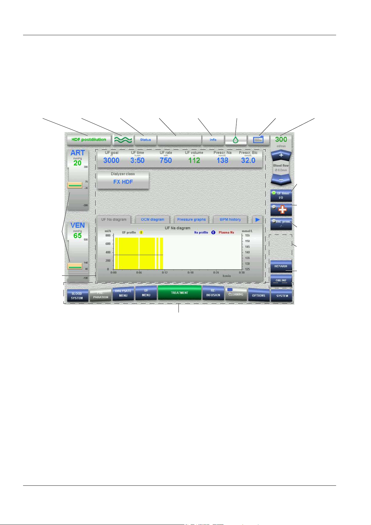
Info 4-3, 9-1
Infusion solution
Infusion solutions, administering
6-7, 6-22
Initial start-up
Intended use
International service
ISO-UF (Sequential therapy)
11-52
IV pole
3-4, 3-5
6-7, 6-22
2-6, 11-42
2-4
2-8
11-7,
K
Kinking warning 10-14
Kt/V
15-1
Kt/V warning
10-22
L
LAN (network) 3-15, 11-15, 22-1
Leakage sensor, extracorporeal
blood module
Leakage sensor, filter chamber
LED/keys
Level detector
Level, setting level in SN chamber
6-12
Level, setting the level in the
venous bubble catcher
Line guide
11-38, 11-40
Line guides
Line holder (for transport)
Line holder for SafeLine™
Lines, removing all
Lines, removing during
Preparation
Lines, removing during treatment
10-29
Loudspeaker
3-8
3-4
3-6
3-11, 11-11
10-31
3-10, 11-34, 11-36,
3-8
3-2
3-9
10-30
10-28
3-7
M
Manufacturer 2-8
Materials
Materials used
Menu buttons
Menu panel
Menu structure, design
11-17, 11-20
11-17
4-3
4-3
4-6
Message button
Messages
Micro bubbles
Micro bubbles removal
Micro bubbles, overriding
Miscellaneous
Monitor
Monitor arm
3-1, 3-6, 3-7
4-2
9-1
9-7
9-10
9-9
10-23
3-7
N
Network (LAN) 3-15, 11-15, 22-1
Numeric keypad
4-7
O
OCM 10-22, 11-13, 11-27, 15-1
OCM (menu)
Online (bolus)
ONLINE preparation
ONLINE preparation with SingleNeedle
ONLINEplus™
6-1, 6-9, 7-1, 7-9, 10-21, 11-24,
11-28, 16-1
Operating conditions
Operating mode
Operating mode indicator
Operating programs
Operator Setup
Optical detector
5-39, 5-55, 11-11
Outage (power failure)
Outlet line
Override conditions
Overview (screen)
15-3
6-2, 6-11, 10-21
5-1
5-31
3-9, 5-1, 5-31,
11-5
4-2
3-6
11-7
10-2
3-11, 5-9, 5-25,
9-15
3-14
11-6
4-2
P
Page setup 3-3, 3-4
Particle filter, dialysate
Patient ID (treatment data sheet)
4-3
Patient, connecting with ONLINE
6-1
Patient, connecting with ONLINE
and Single-Needle
Patient, disconnecting with
ONLINE
7-1
3-4
6-9
Patient, disconnecting with
ONLINE and Single-Needle
PatientCard
Potential equalization
Power connection (supply point)
3-2, 3-15
Power failure (outage)
Power failure and battery
operation
Power failure and depleted battery
9-16
Power switch
Preparation
Preparation with rinse solution bag
5-17
Pressure displays
Pressure holding test
Pressure tubing
Prime collection bag
Profiles
6-4, 6-6, 6-14, 6-21
Pulse
Pump segment
11-38, 11-40
Push handle
3-7, 10-20
9-15
3-15
5-1, 11-7
4-3
3-12, 18-2
5-13, 5-29, 5-43, 5-59,
11-14
11-34, 11-36,
3-2
R
Rear view 3-2
Recessed handle
Recirculating adapter (SafeLine™)
11-35, 11-39
Recirculation
Recirculation measurement
Recycling
Reinfusion
Repair
Residual disinfectant, checking
8-5
Restrictions
Rinse connector
Rinse port
Rinse port catch (grey)
Rinse solution bag
Rinse/reinfusion volume
Rocker switch
Room temperature
Rotor
11-17
7-1, 10-3
2-7
3-8
3-10
3-7
11-31
2-4
11-35, 11-39
11-36, 11-41
4-8
10-25
7-9
3-14, 11-42
9-15
11-8
11-37, 11-41
11-14
3-8
10-3
Fresenius Medical Care 5008 OP 5/09.06 1-3
Page 12

Chapter 1: Index
S
SafeLine™ 11-35, 11-39
SafeLine™ line guide
11-39
SafeLine™ pump segment
11-39
SafeLine™, connecting/retrofitting
10-30
SafeLine™, removing
Safety precautions
Safety precautions (basic)
Safety precautions (electric
hazards)
Safety precautions, signification
2-2
Sampling
Screen
Screen colors
Screen failure
Screen failure, no screen reaction
9-17
Screen failure, screen dark or
display distorted
Screen saver
Screen, cleaning
Selection screen
Service Central Europe
Service door
ServiceCard
Setting via numeric keypad
Setting via rocker switch
Settings, SYSTEM SCREEN
Setup
Shunt door
Shunt interlock
Side effects
Single programs
Single-Needle
11-25, 11-29, 11-53
Single-Needle Click-Clack
10-32, 11-12, 11-23
Single-Needle pressure port
Single-Needle pump
smartbag
SN chamber
SN line guide
2-6
10-28
3-6, 4-2
4-4
9-17
4-9
3-2
3-7
10-2
3-4, 3-5
2-4
3-12, 10-23, 11-13,
24-1
11-13, 11-39, 11-41
11-39, 11-41
11-35,
11-35,
10-29
2-5
2-5
9-17
8-5
4-1
2-8
4-7
4-8
10-1
3-4
10-18
10-23,
3-12
3-12
SN pressure line
SN pump segment
Sodium profiles
5-59, 6-4, 6-6, 6-14, 6-21
Specifications
Start-up requirements
Start-up screen
Status
4-2
Storage
Stroke volume
Substituate catch (blue)
Substituate connector
(SafeLine™)
Substituate port
Substituate pump
Substitution
Supply point
Surface cleaning
Symbols
System description
11-16
11-54
11-39, 11-41
11-39, 11-41
5-13, 5-29, 5-43,
11-1, 11-44
4-1
11-13
11-35, 11-39
3-8
3-8
10-21
3-2, 3-15
8-5, 12-3
11-1, 11-22
T
T1 test 11-7
Technical documentation
Technical measurement checks
(TMC)
2-6, 11-47, 11-54
Technical safety checks (TSC)
2-6, 11-47
Terms
11-52
TMC
2-6, 11-47, 11-54
Transmembrane pressure
11-53
Transportation
Tray for disinfectant container
Treatment
Treatment data sheet
TSC
2-6, 11-47, 11-54
Tubing system, inserting with
ONLINE
Tubing system, inserting with
ONLINE in case of Single-Needle
5-38
Tubing system, inserting with rinse
solution bag
Tubing system, inserting with rinse
solution bag in case of SingleNeedle
5-54
11-16
6-1
5-8
5-24
2-6
3-8
4-3
2-7
11-8,
3-14
Turning power off
Turning power on
5-47
Type label
11-1
8-6
5-1, 5-17, 5-31,
U
UF menu 5-13, 5-14, 5-28, 5-29,
5-43, 5-44, 5-58, 5-59
UF parameters
5-58, 6-3, 6-6, 6-14, 6-21
UF profiles
6-4, 6-6, 6-14, 6-21
UF Timer I/O
UFK-Messung
Ultrafiltration
User interface
UserCard
5-12, 5-28, 5-42,
5-13, 5-29, 5-43, 5-59,
4-3
11-9
10-13, 11-8
10-14
3-7
V
Venous blood line 11-35, 11-36,
11-38, 11-40
Venous bubble catcher
5-39, 5-55, 11-35, 11-36, 11-38,
11-40
Venous injection site/collection
site
11-34, 11-36, 11-38, 11-40
Venous line, removing
Venous measuring head (BTM)
3-12
Venous monitoring function
3-11
Venous occlusion clamp
Venous patient connection
11-36, 11-39, 11-40
Venous pressure
Venous pressure line
11-36, 11-38, 11-40
Venous pressure measurement
11-11
Venous pressure port
Venous transducer
Vent (mixing chamber)
Vent (water inlet chamber)
4-3
10-14
W
Warning 9-1
Warranty
2-5
5-9, 5-25,
10-29
3-8,
3-8
11-35,
11-34,
3-9
3-14
3-14
1-4 Fresenius Medical Care 5008 OP 5/09.06
Page 13

Water alarms 11-53
Water supply
Water supply (permeate)
Weekly programs
Weight
WET
23-1
11-44, 11-45
10-18
11-1
Chapter 1: Index
3-14
Fresenius Medical Care 5008 OP 5/09.06 1-5
Page 14

Chapter 1: Index
1-6 Fresenius Medical Care 5008 OP 5/09.06
Page 15

Chapter 2: Important Information
2 Important Information
2.1 Important Information on the Operating Instructions
2.1.1 How to Use the Operating Instructions
Identification The document can be identified by the following information on the title
page and on the labels, if any:
– Software version of the system
– Edition of the technical document
– Part number of the technical document
Page identification The page identification 1-3, for example, refers to Chapter 1, page 3.
Editorial information The editorial information 1/01.05, for example, refers to: 1. edition,
January 2005.
Changes Document changes will be released as new editions or supplements. In
general, this manual is subject to change without notice.
Importance of the
instructions
Description of the options Chapters 15 to 28 describe the operation of the options. For further
These Operating Instructions are part of the accompanying documents
and an integral part of the system. They contain information necessary
for the use of the system.
The Operating Instructions must be carefully studied before attempting
to operate the system.
Before the responsible organization may start operating the system, the
person responsible for the operation must have been instructed by the
manufacturer on how to use the system and must be thoroughly familiar
with the contents of the Operating Instructions.
The system may only be operated by persons certificated to have been
instructed on the proper operation and handling of the unit.
information please refer to the appropriate chapters. (e.g. The SN
Specifications are listed in chapter 11 System Description.)
Fresenius Medical Care 5008 OP 5/09.06 2-1
Page 16

Chapter 2: Important Information
2.1.2 Signification of the Safety Precautions
Explanation of the Caution and Note symbols used:
Caution
Advises the operator against certain procedures or actions that could
cause damage to the equipment or may have adverse effects on
individuals.
Note
Informs the operator that in case of a failure to follow the steps as
described, a specific function will be executed incorrectly or will not be
executed at all, or will not produce the desired effect.
2.1.3 Signification of the Highlight Symbol
Explanation on the following symbol:
Here you will find hints on easy handling.
2-2 Fresenius Medical Care 5008 OP 5/09.06
Page 17

2.2 Important Information on the System
2.2.1 Brief Description
Dialysis treatments with the hemodialysis system 5008 can be
performed without any additional equipment. The hemodialysis system
controls and monitors the dialysate circuit and the extracorporeal blood
circuit.
The monitor comprises of four keys. All entries are made via a highresolution color monitor (touch screen). The current treatment data are
shown on the display.
In the dialysate circuit, product water is heated, degassed, mixed with
hemodialysis concentrate, and delivered to the dialyzer. Inflowing and
outflowing quantities are balanced volumetrically. The pressure at the
dialyzer is adjusted depending on the ultrafiltration rate selected and the
type of dialyzer used.
Chapter 2: Important Information
The blood in the extracorporeal blood circuit is transported through the
dialyzer. The blood can be continuously heparinized. An air bubble
detector prevents infusion of air. Any dangerous loss of blood is
prevented by a blood leak detector, a fluid detector and by monitoring
the venous return pressure. The arterial pressure monitoring unit
detects an aspiration of the needle in the vessel.
The hemodialysis system 5008 is designed for both acetate dialysis and
bicarbonate dialysis. The mixing ratio, the Na
bicarbonate concentration may be programmed within certain limits.
The hemodialysis system allows programming of Na and UF profiles.
ISO-UF (ultrafiltration without dialysate flow) may be performed.
The dialysate flow can be adjusted from 100 to 1000 ml/min, in
increments of 100 ml/min. The AutoFlow function automatically
regulates the dialysate flow, depending on the dialyzer type and blood
flow.
The 5008 hemodialysis system reflects the latest state of technology. It
is equipped with all safety systems required for its function and for
patient safety. It complies with the requirements of EN 60601-1 (IEC
601-1). The BPM (optional) complies with the EN 1060-1 standard for
non-invasive sphygmomanometers, Part 1 General Requirements.
+
concentration and the
The 5008 hemodialysis system is classified as Class II b (MDD)
equipment.
Fresenius Medical Care 5008 OP 5/09.06 2-3
Page 18

Chapter 2: Important Information
2.2.2 Intended Use
O Fields of application
O Side effects
O Contraindications
The 5008 hemodialysis system is designed for performing chronic and
acute hemodialysis. It can be used in home dialysis, hemodialysis and
limited care centers and clinical hemodialysis.
Hemodialysis therapies occasionally cause hypotension, nausea,
vomiting and cramps in some patients. In addition, the package inserts
enclosed with the consumables (e.g. hemodialysis concentrates,
dialyzers) must be observed.
– Hyperkalemia (only with potassium-containing hemodialysis
concentrates)
– Hypokalemia (only with potassium-free hemodialysis concentrates)
– Uncontrollable coagulation anomalies
A different method of extracorporeal treatment may be indicated in
hemodynamically unstable patients.
O Restrictions
None
2.2.3 Target Group
The system may only be installed, operated and used by persons with
the appropriate training, knowledge and experience.
2.2.4 Duties of the Responsible Organization
The responsible organization assumes the following responsibilities:
– Compliance with the national or local installation, operation, use and
maintenance regulations
– Respect of the accident prevention regulations
– Correct and safe state of the system
– Permanent availability of the Operating Instructions
2-4 Fresenius Medical Care 5008 OP 5/09.06
Page 19

2.2.5 Disclaimer of Liability
2.2.6 Guarantee / Warranty
Chapter 2: Important Information
The system has been approved for use with the consumables and
accessories listed in the Operating Instructions.
Should the responsible organization wish to use other consumables
and accessories than those listed in the Operating Instructions, the
responsibility to ensure the correct function of the system lies
exclusively with the responsible organization. The applicable legal
regulations must be complied with (e.g. in Germany the Medical Device
Directive, MDD and the MPBetreibV = German regulation for the
operation of medical products).
The manufacturer does not assume any responsibility or liability for
personal injury or other damage and excludes any warranty for damage
to the system resulting from the use of non-approved or unsuitable
consumables or accessories.
O Guarantee
O Warranty
2.2.7 Safety Precautions
O Basic safety precautions
For guarantee refer to the respective sales contracts.
The customer's rights of warranty depend on the applicable legal
regulations.
Caution
When using a RO unit or CDS the following must be observed:
Operating Instructions of the RO unit or CDS used.
When cleaning the RO unit and its supply lines, the hemodialysis
system must be disconnected from the RO unit at the water supply.
During cleaning of the CDS distribution tubings, the hemodialysis
system must be separated from the CDS.
Fresenius Medical Care 5008 OP 5/09.06 2-5
Page 20

Chapter 2: Important Information
O Electric hazards
Caution
The use of additional extension cables or multiway sockets / connectors
is prohibited.
2.2.8 Additional Optional Equipment Supplied by Fresenius Medical Care
– DIASAFE®plus
– AquaUNO (single station ´reverse osmosis unit)
For connecting the AquaUNO to the 5008 hemodialysis system, the
two following cables must be used:
Control cable connection set: 3 meters (part no.: M37 525 1) or
11 meters (part no.: M37 510 1)
Adapter cable AquaUNO - 5008 (part no.: M36 940 1)
2.2.9 Initial Start-Up
2.2.10 Start-Up Requirements
2.2.11 Operation
Prior to the initial start-up thoroughly study the information given in
chapter 11.
The 5008 hemodialysis system must be in a perfect state. If the 5008
hemodialysis system shows signs of mechanical damage preventing
safe operation, stop using the machine. Applied parts that are damaged
must be replaced.
The following must be observed when entering parameters:
The parameters entered must be verified by the operator, i.e. the
operator must check that the values entered are correct. If the
verification reveals a deviation between the desired parameters and the
parameters displayed on the system, the setting must be corrected
before activating the function.
The actual values displayed must be compared with the desired values
specified.
2.2.12 Technical Safety Checks (TSC), Technical Measurement Checks (TMC)
The technical safety checks and technical measurement checks
required must be performed every 2 years.
2-6 Fresenius Medical Care 5008 OP 5/09.06
Page 21

2.2.13 Repair
2.2.14 Technical Documentation
Chapter 2: Important Information
Assembly, extensions, adjustments, modifications or repairs may only
be carried out by the manufacturer or persons authorized by him.
Upon request the manufacturer will provide circuit diagrams,
descriptions, spare parts lists and other documents. These are intended
to support trained personnel in servicing and repairing the machine.
The following is also available on request:
– Test procedure by which the effectiveness of sterilization or
disinfection has been verified.
– Comments, concerning the expected recirculation of the blood flow
in the extracorporeal circuit in Single-Needle treatments, if the
recommended administration sets, dialyzers, fistula needles and
catheters are used.
Fresenius Medical Care 5008 OP 5/09.06 2-7
Page 22

Chapter 2: Important Information
2.3 Addresses
Manufacturer Fresenius Medical Care AG & Co. KGaA
Please address any inquiries to:
D-61346 Bad Homburg
+49 (0)6172/609-0
www.fmc-ag.com
Service
Central Europe
International
Service
Local Service
Fresenius Medical Care
Deutschland GmbH
Geschäftsbereich Zentraleuropa
Kundendienst / Servicecenter
Steinmühlstraße 24
61352 Bad Homburg
Germany
Phone: +49 6172 609-7100
Fax: +49 6172 609-7102
E-mail: ServicecenterD@fmc-ag.com
Fresenius Medical Care
Deutschland GmbH
Service Support International
Hafenstrasse 9
D-97424 Schweinfurt
Germany
Phone: +49 9721 678-333 (hotline)
Fax: +49 9721 678-130
2-8 Fresenius Medical Care 5008 OP 5/09.06
Page 23
3Design
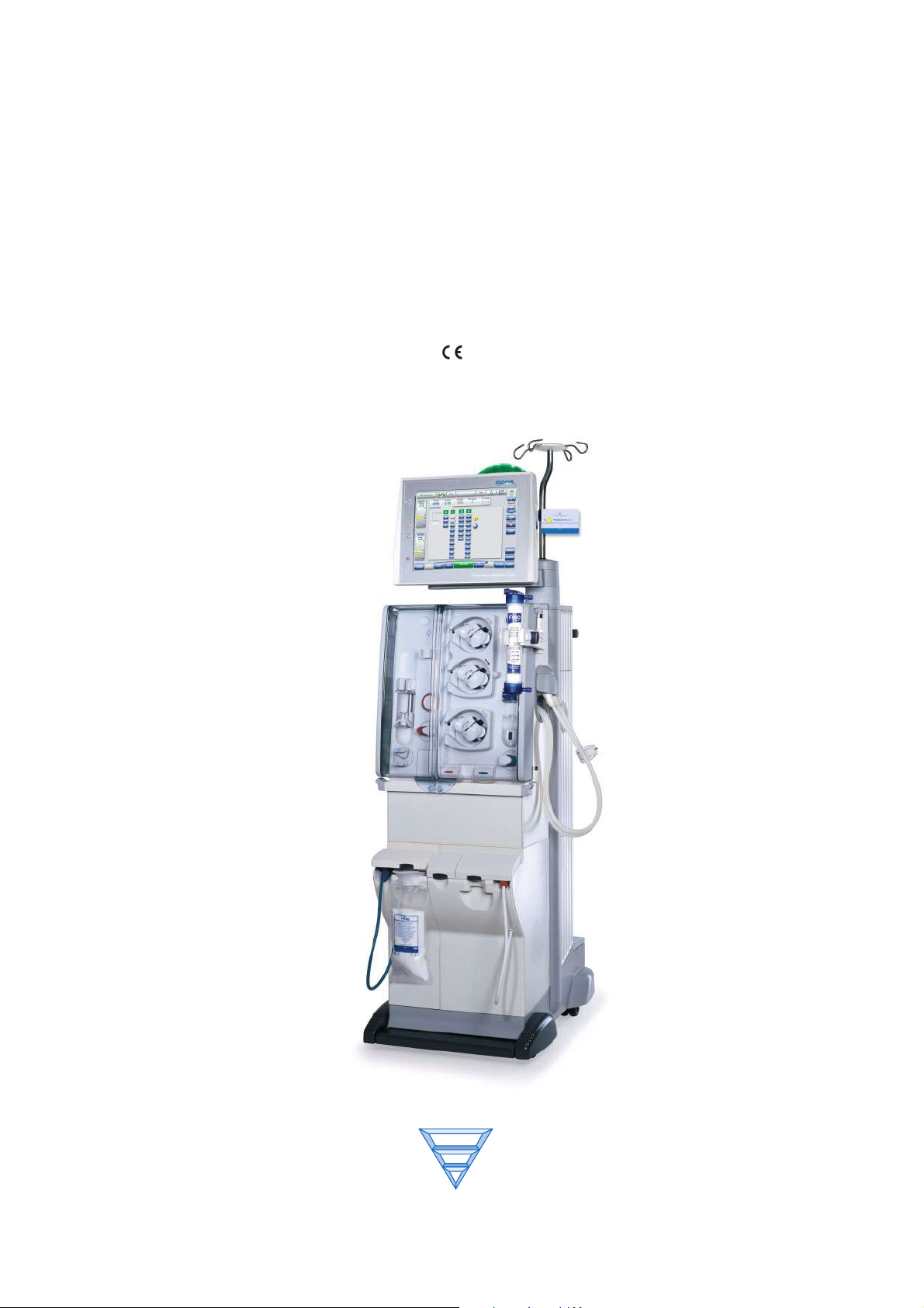
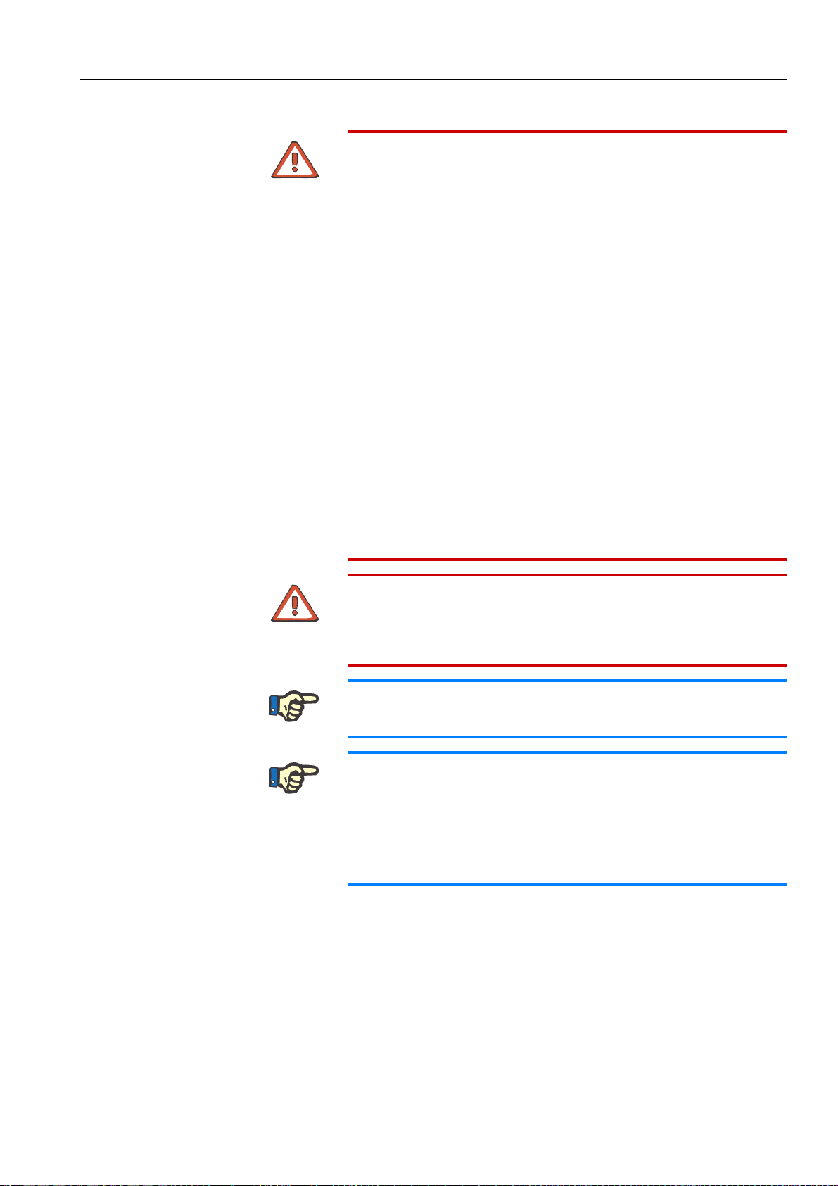
3.1 Front View
1
Chapter 3: Design
1 Monitor
2 Extracorporeal blood module
3 Hydraulics
2
3
Fresenius Medical Care 5008 OP 5/09.06 3-1
Page 24
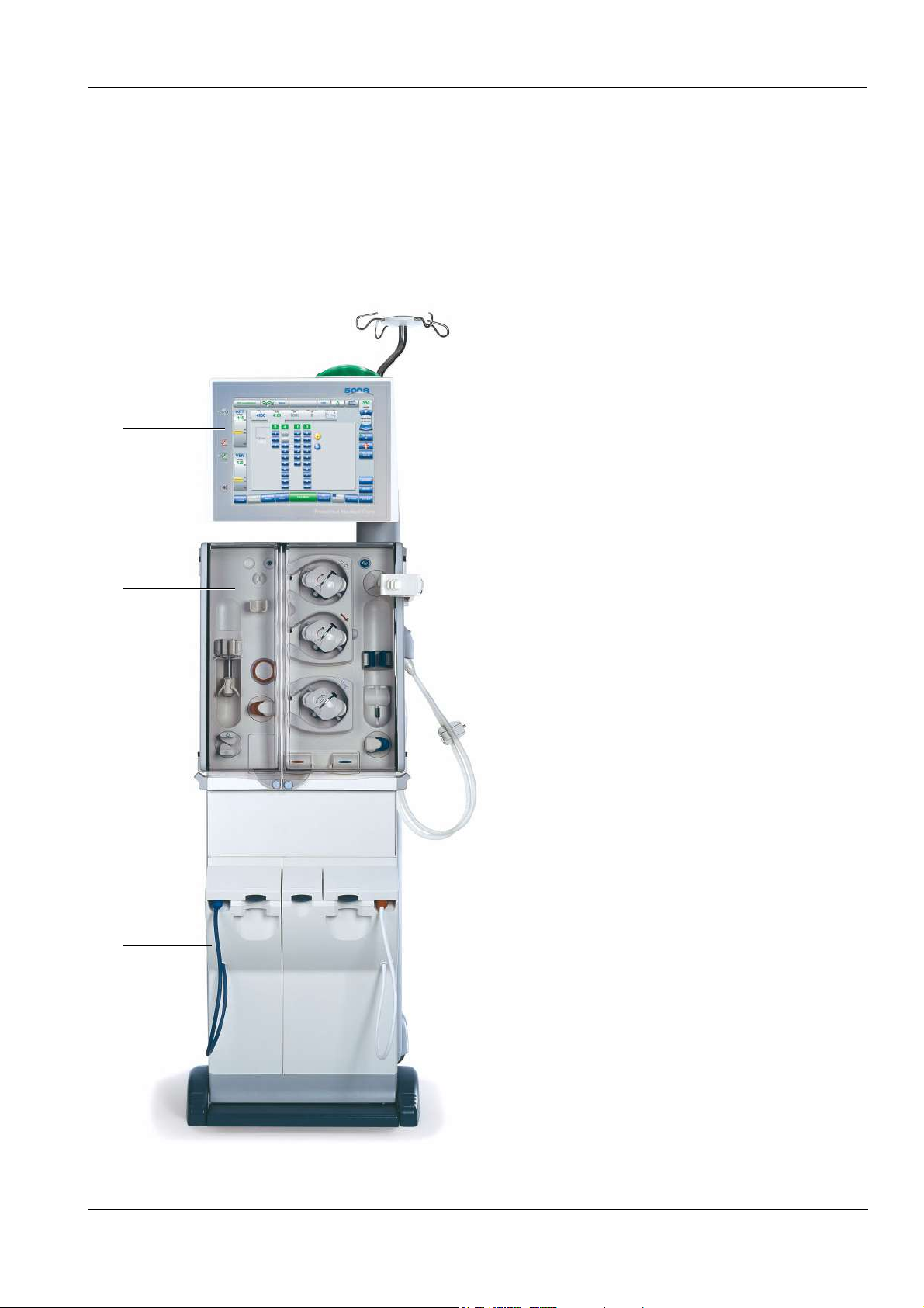
Chapter 3: Design
3.2 Rear View
1 Monitor
2 External connection options
3 Push handle
4 Fan filter (service door)
5 Power connection (supply point)
1
6 Line holder (for transport)
7 Service door
8 Hydraulic connectors
2
3
4
5
6
7
8
3-2 Fresenius Medical Care 5008 OP 5/09.06
Page 25
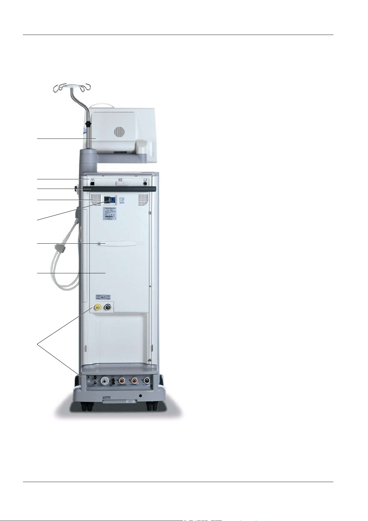
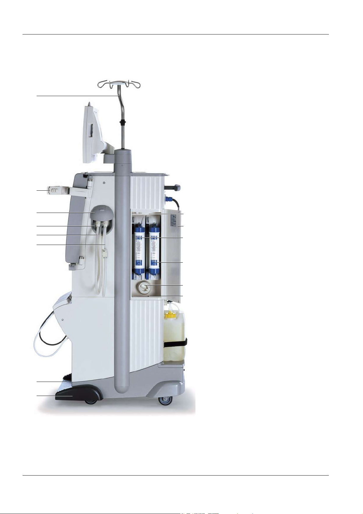
3.3 Lateral View, Left Side
Chapter 3: Design
1 Cover, tray, cuff holder or shunt
interlock
2 Concentrate rack (extractable)
3 Brake
Remove the cover from the tray:
(a) Push the cover down and turn it.
(b) Pull the cover out.
a
b
To extract the concentrate rack:
1
Push with your foot from the front against the
rack.
To retract the concentrate rack:
Push with your foot from the front against the
rack until it clicks into place.
To apply or release the brake:
(a) Push the lever down to apply the brake.
(b) Push the lever down to release the brake.
a
2
3
b
Fresenius Medical Care 5008 OP 5/09.06 3-3
Page 26
Chapter 3: Design
3.4 Lateral View, Right Side
1 IV pole
1
2 Dialyzer holder
3 Shunt door for dialysate lines
4 Shunt interlock
5 Dialysate return line
(dialyzer coupling blue)
6 Dialysate supply line
(dialyzer coupling red)
7 Concentrate rack (extractable)
8 Brake
9 Leakage sensor, filter chamber
2
3
4
5
6
14
13
12
11
10 Particle filter, dialysate
11 Filter 1 – DIASAFE
®
plus, right
12 Filter 2 – ONLINEplus™, left
13 Door, filter chamber
14 Filter chamber
10
9
7
8
3-4 Fresenius Medical Care 5008 OP 5/09.06
Page 27
Chapter 3: Design
To adjust the IV pole:
Push the knob (a) upwards and
b
a
simultaneously extract or retract the IV pole
(b).
Dialyzer holder:
b
Push the lever (a) to the left to insert the
c
dialyzer. The dialyzer can be moved to any
desired position (b). Press or pull the lever (c)
to swivel the dialyzer holder to the right.
a
(When the right-hand door is opened, the
dialyzer holder will automatically move to the
right.)
To open or close the shunt door:
b
Open the shunt door by flipping it to the top
(a). Close the shunt door by flipping it down
a
(b).
To remove the dialysate couplings:
Push the lever down and hold it, and remove
the dialysate coupling.
To move the hemodialysis system:
The hemodialysis system can be moved in all
directions.
Fresenius Medical Care 5008 OP 5/09.06 3-5
Page 28

Chapter 3: Design
3.5 Monitor Front
1
2
7
3
4
5
6
1 Display failure sensor (hidden)
2On/Off LED/key (green)
(LED is illuminated – system in operation. LED is flashing – system
is connected to power supply, standby.)
3 Blood system Stop LED/key (red)
4 Blood system Start LED/key (green)
5Mute LED/key (red)
(LED is illuminated – audible alarm suppressed. LED is flashing –
audible alarm active.)
6 Screen
7 Operating mode indicator (green, yellow, red)
LED is green to indicate correct operation.
LED is yellow in case of a warning or an info.
LED is yellow and flashing in Emergency mode.
LED is red in case of an alarm.
LED is not illuminated during the cleaning programs.
3-6 Fresenius Medical Care 5008 OP 5/09.06
Page 29
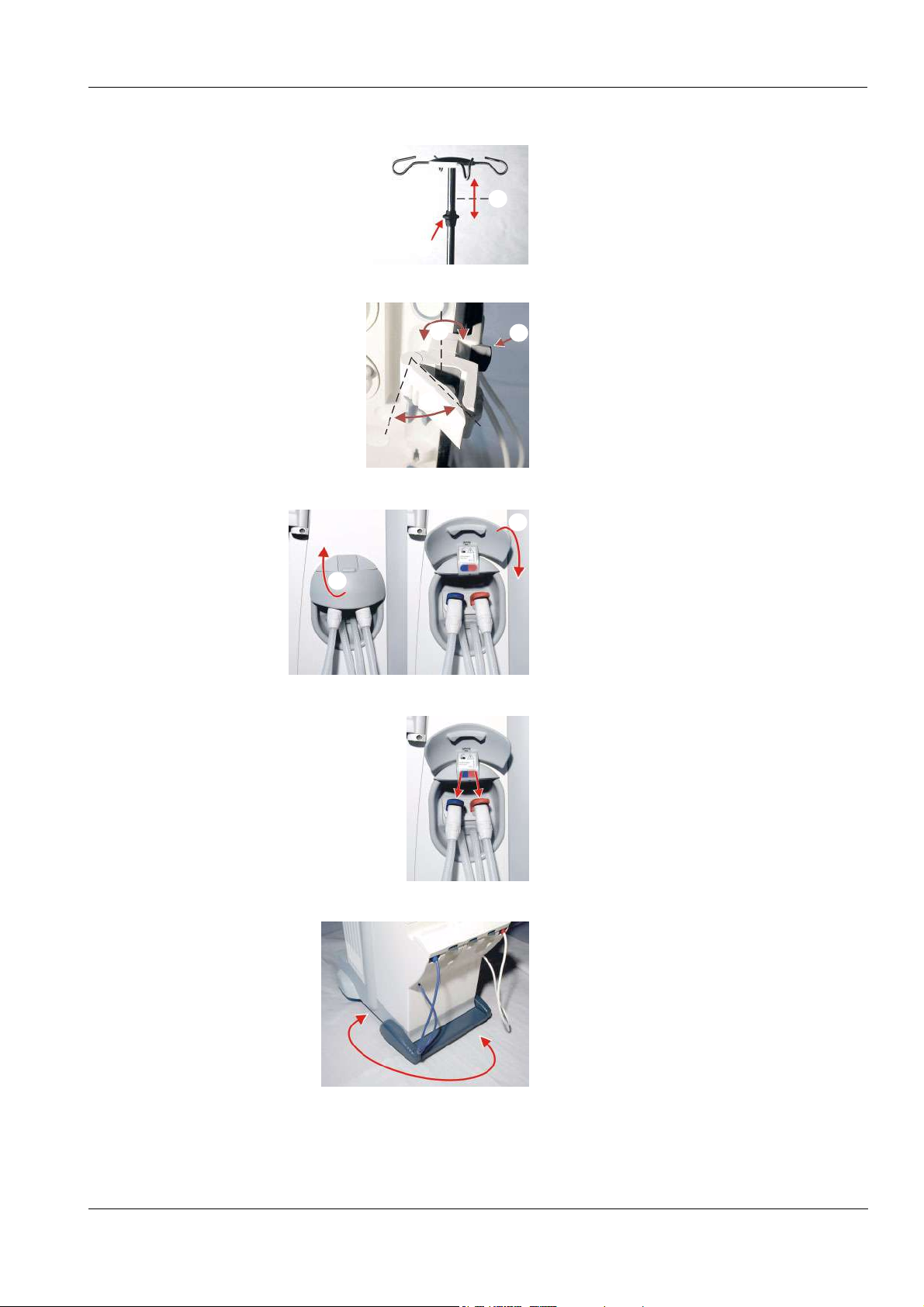
3.6 Monitor Rear
1
2
3
Chapter 3: Design
4
1 Card receptacle
(for PatientCard/UserCard/ServiceCard)
2 Loudspeaker
3 Recessed handle
4 Monitor arm
To move the monitor:
To bring the monitor into the desired position,
it can be swiveled about three axes (a), (b),
(c).
a
b
c
(a) To move it, hold the monitor at the points
shown.
(b) Insert card.
a
b
Fresenius Medical Care 5008 OP 5/09.06 3-7
Page 30
Chapter 3: Design
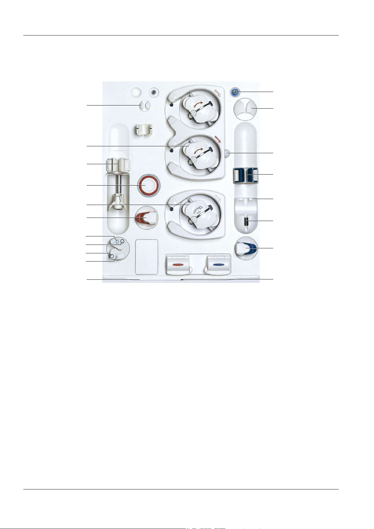
3.7 Extracorporeal Blood Module
19
10
11
1
2
3
4
5
6
7
8
9
18
17
16
15
14
13
12
1 Line holder
2 Blood pump
3 Heparin pump (if present)
4 Arterial pressure measurement unit
5 Substituate pump
6 Arterial occlusion clamp
7 Substituate catch/lock (blue)
8 Substituate port, hidden by the substituate catch (blue)
9 Rinse port, hidden by the rinse port catch (grey)
10 Rinse port catch (grey)
11 Groove
12 Leakage sensor, extracorporeal blood module
13 Venous occlusion clamp
14 Venous monitoring function (optical detector, air bubble detector)
15 Locator for venous bubble catcher
16 Venous monitoring function (level detector)
3-8 Fresenius Medical Care 5008 OP 5/09.06
Page 31

17 Line holder for SafeLine™
18 Line holder
19 Venous pressure port
Open or close the doors on the upper side as
shown in the illustration.
Chapter 3: Design
Fresenius Medical Care 5008 OP 5/09.06 3-9
Page 32
Chapter 3: Design
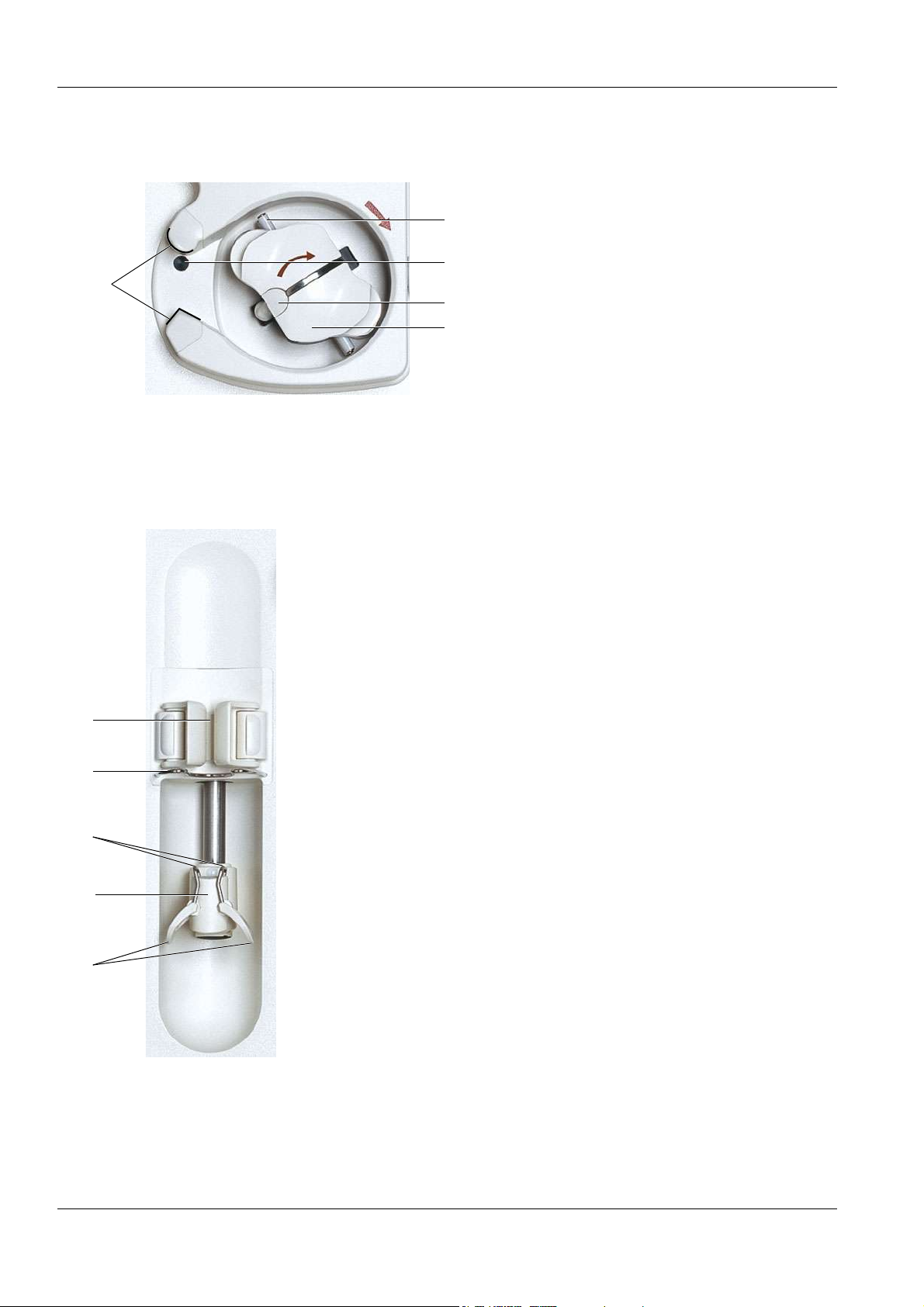
O Blood pump
1 Holder (shape-coded) for line guide
1
O Heparin pump
5
2 Rotor
3 Handle for an emergency operation
4
3
2
4 Key/ejector (for inserting and removing
the line segment)
5 Line pulleys
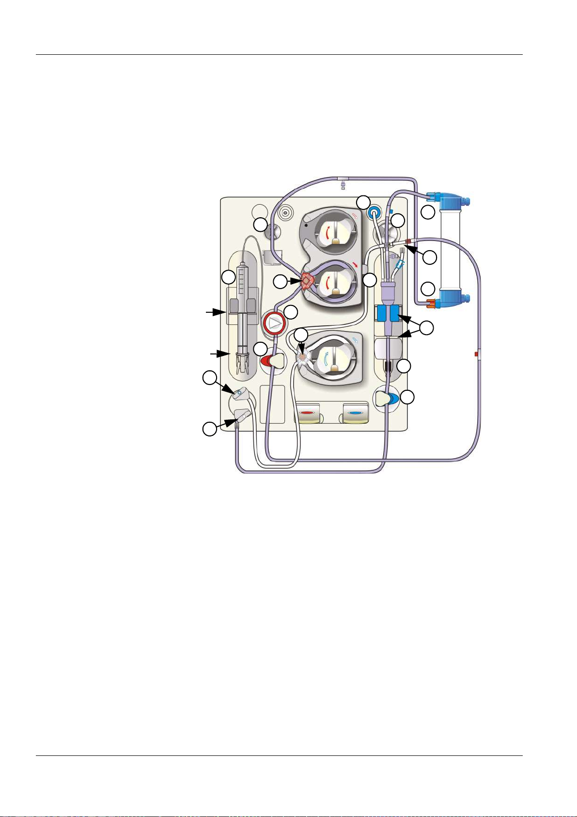
1 Barrel holder with syringe detector
2 Bracket
3 Fixation for the plunger
4 Grip handle
5 Clamping brackets
1
2
3
4
5
3-10 Fresenius Medical Care 5008 OP 5/09.06
Page 33
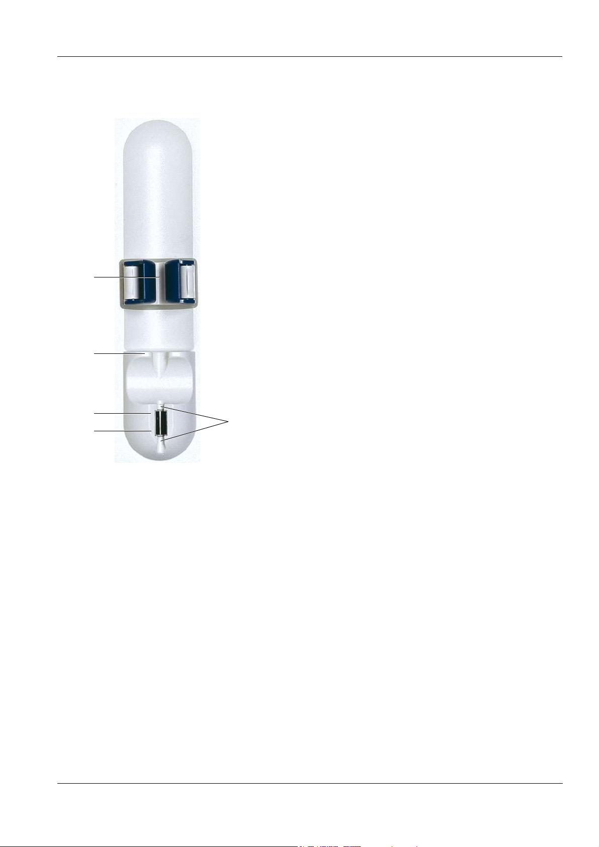
O Venous fill level and air monitoring function
1
Chapter 3: Design
1 Tension lever with level detector (for the
venous bubble catcher)
2 Locator for venous bubble catcher
3 Optical detector
4 Air bubble detector (ABD)
5 Line housing
2
3
4
5
Fresenius Medical Care 5008 OP 5/09.06 3-11
Page 34

Chapter 3: Design
3.8 Extracorporeal Blood Module with Additional Functions
5
6
1
2
3
4
7
8
9
10
BPM (option) 1 Blood pressure cuff
2 Cuff holder
3 Pressure port (BPM)
4 Pressure tubing
SN (option) 5 Single-Needle pressure port
6 Single-Needle pump
7 Holder for SN chamber (with mark)
BVM (option) 8 BVM measuring head
BTM (option) 9 Arterial measuring head (BTM)
10 Venous measuring head (BTM)
3-12 Fresenius Medical Care 5008 OP 5/09.06
Page 35
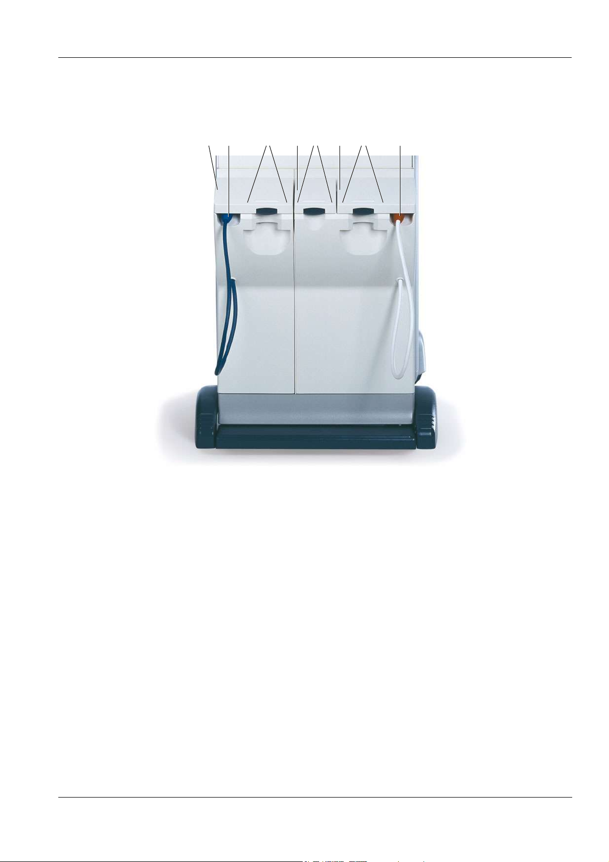
3.9 Hydraulics
Chapter 3: Design
321 54 786
1 Bicarbonate flap
2 Bicarbonate suction tube (blue)
3 bibag
®
port
4 Indibag flap
5 indibag
®
port
6 Concentrate flap
7 sobag
®
port
8 Concentrate suction tube (red)
Fresenius Medical Care 5008 OP 5/09.06 3-13
Page 36

Chapter 3: Design
3.10 Hydraulics Connectors
1
2
3
4
10 11
8
12 139765
1 Disinfectant connector (left – colored coding, yellow)
2 Disinfectant connector (right – colored coding, black)
3 Holder for disinfectant container
4 Tray for disinfectant container
5 Potential equalization
6 Drain
7 Flush drain (option)
8 Water supply (permeate)
9 Vent (water inlet chamber)
10 Vent (mixing chamber)
11 Connector for CDS 1, red (Central Delivery System) acid 1
12 Connector for CDS 2, red (Central Delivery System) acid 2
(option)
13 Connector for BIC, blue (central bicarbonate supply) (option)
3-14 Fresenius Medical Care 5008 OP 5/09.06
Page 37
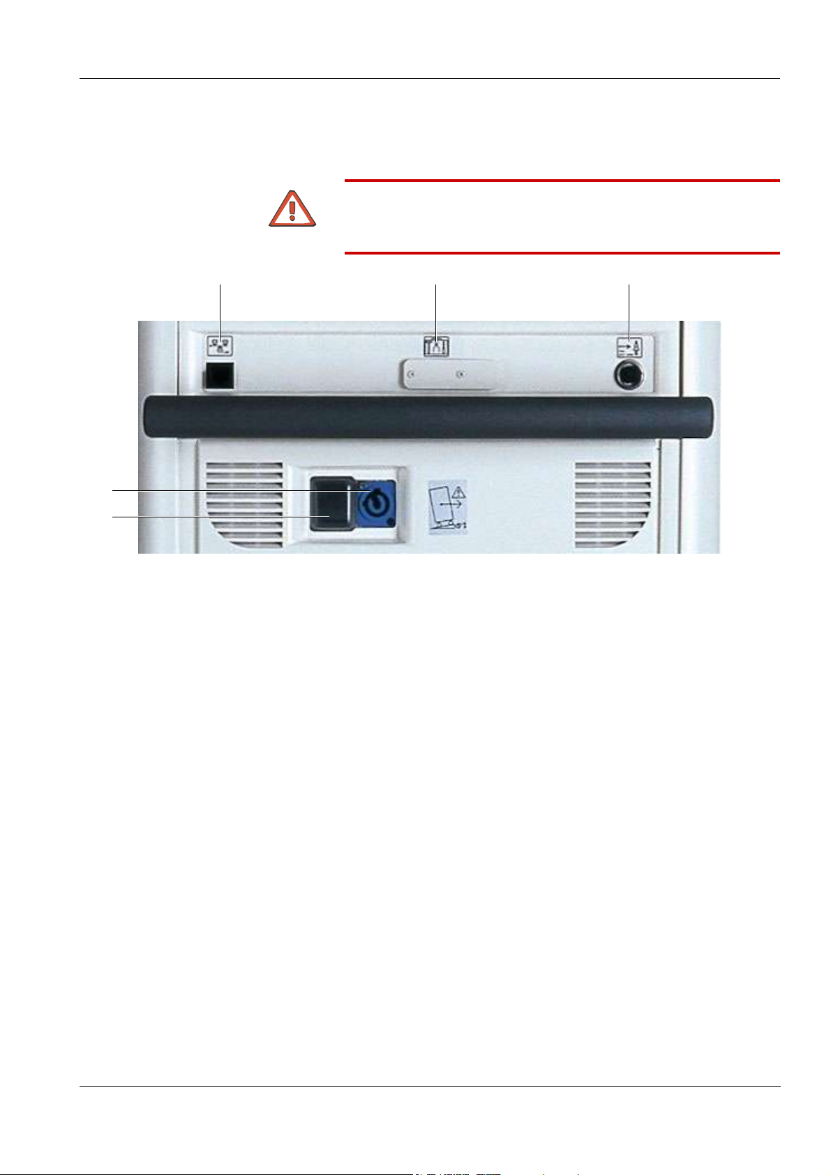
Chapter 3: Design
3.11 External Connection Options/Connection to Power Supply
Caution
Before connecting any optional equipment, observe the notes under
Specifications.
1
4
5
1 LAN (local area network) network connection
2 Service/diagnostics, RS232, 24 V
Connector for AquaUNO (single station reverse osmosis unit)
3 Alarm output (staff call)
4 Power connection (supply point)
2 3
5 Power switch
Fresenius Medical Care 5008 OP 5/09.06 3-15
Page 38

Chapter 3: Design
3-16 Fresenius Medical Care 5008 OP 5/09.06
Page 39

4 Graphical User Interface
4.1 After Turning Power on to the System
START-UP SCREEN
The display shows the machine type, the
current software version and the clinical data
(on request) for approx. 15 seconds.
Chapter 4: Graphical User Interface
SELECTION SCREEN
The following selections are possible:
– Treatment
– Cleaning program (e.g. Rinse)
Touch the desired button to make your
selection.
Fresenius Medical Care 5008 OP 5/09.06 4-1
Page 40
Chapter 4: Graphical User Interface
4.2 Overview (Screen)
Operating
mode
1 2 3 4 5 6 7 8
16
Pressure
displays
15
Menu
section
Status
indicator
Dialysate flow
Status Blood flowPatient IDStatus
Message
button
Info
indicator
Heparin
9
UF Timer I/O
10
Emergency
Button
11
Blood
pressure
12
Options
menus
13
HEPARIN
14
Menu buttons
1 Operating mode
Displays the operating mode of the system (e.g. Dialysis).
In addition, a progress bar is displayed, depending on the
operating mode, e.g. in the Rinse mode.
2 Dialysate flow status indicator
– Flow turned on – waves green (grey bar is moving.)
– Bypass – waves green (grey bar is not moving.)
– Flow turned off – waves grey
3 Status
Displays data on the system condition. (Software, error memory,
cleaning status, system info)
4 Message button
Allows retrieval of information, warnings and alarms (3 maximum)
4-2 Fresenius Medical Care 5008 OP 5/09.06
Page 41

Chapter 4: Graphical User Interface
5Info
Displays information on the current procedure.
6 Heparin status indicator
– Pump switched on – drop green
(Grey bar is moving.)
– Pump switched off – drop grey
7 Patient ID (patient identification)
Treatment data sheet will be displayed.
Combined with the use of the patient card, it is possible to retrieve
current treatment data. Storage of 3 previous treatments.
8 Blood flow
Displays the effective blood flow.
Rocker switch for increasing + / reducing – the effective blood flow.
9 UF Timer I/O
Button for starting/stopping ultrafiltration and the timer function.
10 Emergency button
11 Blood pressure
(Displayed only, if BPM option is available.)
12 Options menus
Via the OPTIONS menu button, it is possible to program up to
four option menus with direct access.
13 HEPARIN
(displayed only, if selected in the Operator Setup)
14 Menu buttons
Corresponding menu opens automatically during operation
OR
touch button for opening the respective menu.
15 Menu section
In the center of the screen, the appropriate data for each menu is
displayed.
Indicators/buttons/diagrams/graphics are displayed depending on
the Setup settings.
16 Pressure displays
ART (arterial pressure)
VEN (venous pressure)
The actual value is displayed as a numerical value and as a bar.
The alarm window is displayed in block representation, according
to the window size.
Touch the ART or VEN field for setting the alarm limits.
4.3 General Operation Philosophy
It is possible to control all treatment sections via the screen menu.
Fresenius Medical Care 5008 OP 5/09.06 4-3
Page 42
Chapter 4: Graphical User Interface
O Screen colors
The fields in the header bar are:
Grey in the normal operating mode
Orange during the functional test (T1 test)
Orange during rinse procedure of the extracorporeal blood circuit, until the minimum
rinse volume has been reached.
Yellow during the cleaning programs
BLUE
Selection possible
GREEN
Active
GREY
Not active
Example
Examples
UF goal value field
UF MENU button
Examples
UF Timer I/O indicator
TREATMENT button
Emergency menu I/O indicator
Selection not possible
Example
CLEANING button
4-4 Fresenius Medical Care 5008 OP 5/09.06
Page 43
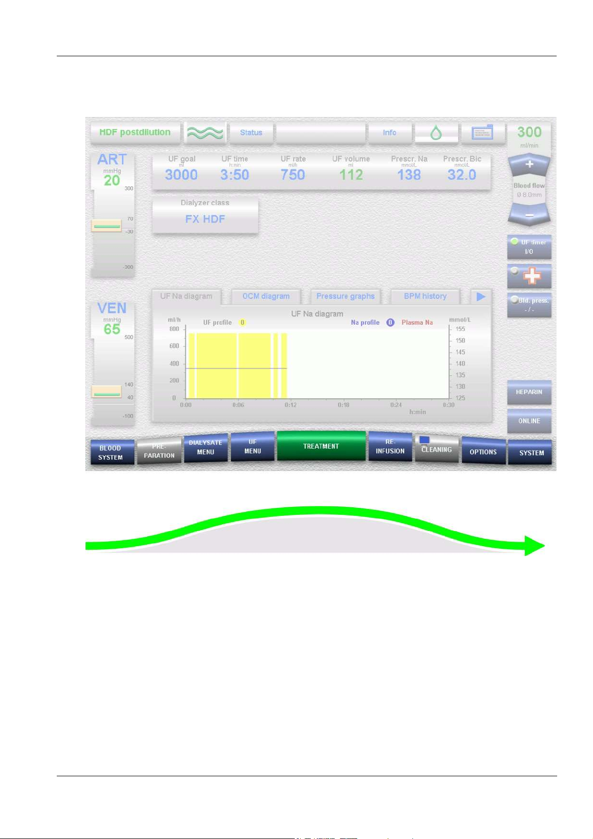
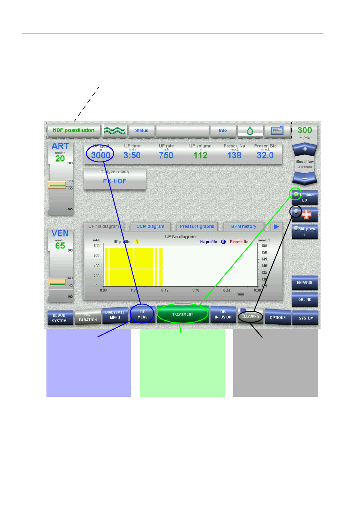
O Course of the treatment
Chapter 4: Graphical User Interface
9 menu buttons in 3-D-design are placed at the bottom screen bar,
representing the chronological course of operation. The change to the
corresponding menus is performed automatically when the respective
conditions have been fulfilled. (Exception: DIALYSATE MENU, UF
MENU, OPTIONS and SYSTEM)
Fresenius Medical Care 5008 OP 5/09.06 4-5
Page 44

Chapter 4: Graphical User Interface
O Design of the menu structure
Treatment data may be
changed directly on the main
screen.
Touching the OK button
accepts changed data.
To enter data for more
parameters, touch this OK
level button to accept the
changed data and to open
the respective menu.
4-6 Fresenius Medical Care 5008 OP 5/09.06
Page 45
Chapter 4: Graphical User Interface
4.4 Examples for Data Entry (Treatment Data)
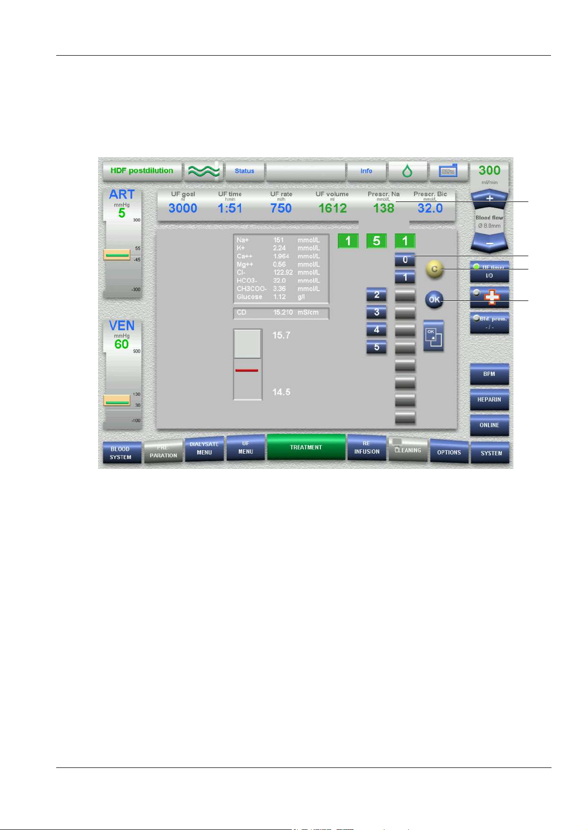
O Setting via the numeric keypad (for example setting the prescribed Na)
1
2
4
3
1. Touch the Prescr. Na field.
2. Enter the desired prescribed Na via the keypad.
Check the entered value (prescribed value).
(Grey keys prevent implausible entries.)
3. Touch the OK button to accept the entered value.
Visually check the accepted value.
4. Touch the C button for making corrections.
Fresenius Medical Care 5008 OP 5/09.06 4-7
Page 46

Chapter 4: Graphical User Interface
O Setting via the rocker switch (for example changing the venous alarm limits)
1 32a 2b 4 5
1. Touch the VEN field.
2. a, Adjustment of window width – left
b, Adjustment of window position – right
3. Adjust the desired alarm window via the
+/– rocker switch.
Check the entered alarm window value in the venous pressure
display (prescribed value).
4. Touch the OK button to accept the selected alarm window.
Visually check the accepted alarm window.
5. Touch the C button for making corrections.
4-8 Fresenius Medical Care 5008 OP 5/09.06
Page 47

4.5 Screen Saver
Chapter 4: Graphical User Interface
SCREEN SAVER
Displays the following data:
– the arterial and the venous pressures
– the UF parameters goal, rate and volume
– the effective blood flow
– the remaining treatment time in the center
– the last measured blood pressure
(Only if the BPM system option exists.)
– the BVM rate and - under UF goal - the maximum UF goal = “+“ as
well as the minimum UF goal = “-“
(Only if the BVM system option exists.)
It is only displayed during the treatment, following a certain timed delay
after the last screen action. (Timed delay adjustable in the Operator
setup.)
The SCREEN SAVER disappears when any part of the screen is
touched.
The SCREEN SAVER disappears immediately:
– when a message is given (info, warning or alarm),
– when the BPM (optional) starts a measurement.
Fresenius Medical Care 5008 OP 5/09.06 4-9
Page 48

Chapter 4: Graphical User Interface
4-10 Fresenius Medical Care 5008 OP 5/09.06
Page 49

Fold-Out Sheet
5 Preparation
Fresenius Medical Care 5008 OP 5/09.06
Page 50

Connecting the concentrate container (e.g. acid) PREPARATION SCREEN
Connecting the bag (e.g. bibag®)
BLOOD SYSTEM SCREEN
DIALYSATE SCREEN
UF SCREEN
PREPARATION SCREEN
HEPARIN SCREEN
Page 51

5 Preparation
5.1 Preparation using ONLINEplus™
Irrespective of the treatment mode, all 5008 ONLINEplus™
hemodialysis systems can be operated without rinse or infusion
solutions provided in NaCl bags. The fluid volumes required for
preparation, bolus administration or during reinfusion will then be
produced ONLINE by the 5008 hemodialysis system according to the
actual requirements, thus saving both cost and time.
5.1.1 Turning the Hemodialysis System On
Caution
Chapter 5: Preparation
The stability of the 5008 hemodialysis system must be ensured.
Establish the water and power supply.
Press the On/Off key. (Turn the hemodialysis system on!)
The On/Off LED is illuminated.
START-UP SCREEN
The display shows the machine type, the current software version and
the clinical data (on request) for approx. 15 seconds.
Caution
After a downtime of more than 72 hours, a cleaning program must be
performed completely before starting the treatment.
If necessary, check the hemodialysis system for presence of residual
disinfectant. (see chapter 8 Cleaning).
Note
If the message: Defective battery is acknowledged by pressing the Skip
key, it might be that the audible alarm will not be generated, if a power
failure occurs.
Fresenius Medical Care 5008 OP 5/09.06 5-1
Page 52

Chapter 5: Preparation
5.1.2 The Following Must be Observed when Using Consumables
Caution
The system has been approved for use with the consumables and
accessories listed in the Operating Instructions.
Should the responsible organization wish to use other consumables
and accessories than those listed in the Operating Instructions, the
responsibility to ensure the correct function of the system lies
exclusively with the responsible organization. The applicable legal
regulations must be complied with (e.g. in Germany the Medical Device
Directive, MDD and the MPBetreibV = German regulation for the
operation of medical products).
The manufacturer does not assume any responsibility or liability for
personal injury or other damage and excludes any warranty for damage
to the system resulting from the use of non-approved or unsuitable
consumables or accessories.
Caution
The symbols printed on the packaging of the consumables have to be
observed. The symbols are described in the chapter System
Description (consumables symbols).
When using consumables, it is important to take note of the following
symbols:
Do not reuse
2
Use by
Caution
The consumables may only be used if the packaging and the respective
consumable including the protective caps used are not damaged. The
protective caps must not have fallen off.
The plastics used for the consumables may not be compatible with
components of drugs or disinfectants. If they are planned to be used,
the compatibility of the consumables' components must be ensured
before the treatment. If connectors made of polycarbonate are for
example exposed to aqueous solutions with the pH value > 10 or to
aliphatic solutions this will cause tension cracks.
5-2 Fresenius Medical Care 5008 OP 5/09.06
Page 53

5.1.3 Selecting the Concentrate Supply
O Connecting the concentrates
Caution
Concentrate:
The concentrate displayed on the screen must comply with the
specifications mentioned on the acid or the acetate container or on the
bag. This also applies to the concentrate composition in CDS operation.
Concentrate packages:
– Assure that the packages used contain sufficient concentrate to
complete the treatment.
– Use only the dedicated coded containers or the bibag
bicarbonate dialysis.
Bicarbonate dry concentrate bibag
Only the bibag
The bibag
Only use the bibag
concentrate according to the prescribed dilution. Other mixing ratios
may lead to a hazard for the patient.
Chapter 5: Preparation
®
®
®
manufactured by Fresenius Medical Care may be used.
®
must only be used for one treatment.
®
in combination with acid bicarbonate hemodialysis
:
for
Acid and basic bicarbonate hemodialysis concentrate have to be diluted
immediately prior to application only. The bag's content must be used
up within 12 hours after dilution. Discard residual volumes. The powder
is non-pyrogenic.
Conductivity limits:
The alarm limits are automatically set around the expected value.
The actual value of the conductivity display must have attained the
expected desired value after a maximum of 10 minutes.
Should this not be the case, the actual value must first be checked in
the laboratory. Change or check the concentrate, if necessary, or call
service.
Note
The bicarbonate suction tube must be inserted into the rinse chamber
during the bibag
®
treatment.
Extract the concentrate rack.
Bicarbonate dialysis To connect the (acid) concentrate container:
Push the latch (1) upwards. Open the concentrate flap. Place the red
concentrate suction tube (2) into the acid container. Close the
concentrate flap (3) until it clicks into place.
Fresenius Medical Care 5008 OP 5/09.06 5-3
Page 54

Chapter 5: Preparation
CDS, Central Delivery
System (option)
Acetate dialysis Connect the concentrate container.
To connect the bibag®:
Push the latch (1) upwards. Open the bicarbonate flap. Remove the
®
bibag
bibag
from its packaging. Remove the foil from the bibag®. Attach the
®
(2). Close the bicarbonate flap (3) until it clicks into place.
OR
To connect the bicarbonate container:
Insert the bicarbonate suction tube (blue) into the bicarbonate
container.
Close the bicarbonate flap.
Note
The responsible organization is responsible for the proper installation
and function of the CDS.
Insert the concentrate suction tube (red) into the acetate container.
The bicarbonate suction tube (blue) remains in the rinse chamber.
Selecting a treatment SELECTION SCREEN
Touch the Treatment field.
If there is no tubing system inserted, the system automatically moves to
the BLOOD SYSTEM screen.
BLOOD SYSTEM SCREEN
The T1 test is now running in parallel with the preparation of the
hemodialysis system. The color of the header bar is orange for the
duration of the T1 test.
The operating mode display shows the progress of the T1 test.
Message: T1 test completed is displayed for a moment after successful
completion of the T1 test.
5-4 Fresenius Medical Care 5008 OP 5/09.06
Page 55

Chapter 5: Preparation
5.1.4 Important Items to be Considered Before and During the Treatment
Caution
Aseptic technique:
Use aseptic technique for all bloodside connections and all connections
in the area where sterile solutions are to be used.
Caution
Preventing contamination:
Use tubing systems with hydrophobic filters at the pressure lines to
prevent cross-contamination.
Connect the hydrophobic filters so that an ingress or loss of air is not
possible and that any wetting by fluid is reliably avoided, also in case of
pressure fluctuations.
If a hydrophobic filter has become wet, the tubing system must be
replaced.
On tubing systems with additional connection sites, a replacement
pressure line may be connected (accessory available from Fresenius
Medical Care).
The blood in the pressure line must not be forced back by means of a
syringe. This could damage the hydrophobic membrane and thus lead
to a contamination.
If fluid may have passed the hydrophobic filter, the system must be
checked for contamination after completion of the treatment. If the
system is contaminated, it has to be taken out of service. All affected
components have to be disinfected or replaced in accordance with the
manufacturer's specifications before the system is put into operation
again.
Fresenius Medical Care 5008 OP 5/09.06 5-5
Page 56

Chapter 5: Preparation
Caution
When inserting the tubing systems, the following precautions
must be respected:
– The tubing systems have to be free of kinks, tension and twists and
must not be jammed (risk of hemolysis). Use the line holders
provided.
– Ensure the correct position of the screwed connections, especially
of the connection sites to the patient, the dialyzer and the system
and check or correct them during the treatment if necessary. Take
the appropriate measures if required (e.g. retightening of the Luer
Lock connection or replacement of the tubing system).
– Check the protective caps for tight fit and tighten them if necessary.
– The lines for the supply of infusions should always be clamped,
except if they are needed.
– During long-term operation, the blood lines must be changed after
24 hours at the latest.
– Do not use cannulas with a diameter of > 20 gauge to pierce the
septum of the injection sites. Insert the cannula vertically and in the
center of the septum. Disinfect the injection sites with 70% alcohol
before use.
– The blood pump must be set to the diameter of the pump segment,
refer also to the product label of the blood lines. If a wrong line
diameter is set, this may cause significant deviations in the blood
flow and thus in the dialysis dose.
– Materials which come directly or indirectly into contact with blood
are: Plasticized PVC, unplasticized PVC, polyethylene,
polycarbonate, latex-free rubber, ABS.
– The minimum temperature of the tubing systems during use is 18 °C.
Caution
Delivery operation of the pump(s) with open doors
(blood pump, substituate pump, optional Single-Needle pump):
When the doors are open and the rotor of the pump(s) is running, make
sure that no objects, such as fingers, hair or ball point pens, come into
contact with the rotor (risk of injury).
Arterial pressure measurement unit:
Prevent foreign objects from coming into contact with the arterial
pressure measurement unit.
Heparin pump:
If heparin syringes of third party suppliers are used, the operator is
responsible and has to ensure that the syringe data displayed match the
actual data.
Heparin syringes without Luer lock are not recommended as the
connection between the heparin syringe and the blood lines may come
loose. If heparin syringes without Luer lock are used it is the operator’s
responsibility to ensure that the connection between the heparin syringe
and the blood lines does not loosen inadvertently.
IV pole:
Securely fix bags or other objects to be hung from the IV pole.
5-6 Fresenius Medical Care 5008 OP 5/09.06
Page 57
Chapter 5: Preparation
Caution
Before the treatment, check:
– The safe connection of all connection sites of the tubing system.
– The tightness of the tubing system during and after priming.
– Retighten the connections and replace the tubing system, if
necessary.
– The absence of air in the tubing system and the correct position of
all fluid levels.
To be observed when working on the tubing system during the
treatment:
If the position of the tubing system or of one of its components is
changed, the correct position of the entire tubing system must be
restored afterwards, above all the correct position of the line guides.
During the treatment check at appropriate intervals:
– The condition of the patient.
– The function of the hemodialysis system and the extracorporeal
blood circuit. Pay particular attention to the venous insertion site, as
a possible dislocation of the venous cannula may not always be
detected by the pressure monitoring system.
– The tubing system for leakages or possible loosening of connections
as well as entry of air.
– The fluid level in the venous bubble catcher. Correct it, if required
(desired level: approx. 1 cm below the upper edge of the cover)
Caution
Venous alarm limit:
The lower venous alarm limit must be set as close as possible to the
actual venous pressure value.
Note
The dialyzer holder is not suitable for rectangular plate dialyzers.
Note
For hygienic reasons, the blood lines should be inserted immediately
prior to the treatment only.
If the blood lines were inserted more than 8 hours before the treatment,
malfunctions may occur. Correcting these malfunctions may require
removing the present blood lines and inserting new blood lines.
Fresenius Medical Care 5008 OP 5/09.06 5-7
Page 58
Chapter 5: Preparation
5.1.5 Preparing the Extracorporeal Blood Circuit with ONLINEplus™
O Inserting the arterial and the venous tubing system
When inserting the tubing system, follow the description of the menu
displayed.
Wings of the
syringe cylinder
Thumb rest of the
syringe plunger
16
17
12
2
6
1
4
13
5
10
14
11
15
3
7
8
9
Open the doors of the Extracorporeal Blood Module.
1 Insert the line guide into the blood pump until a signal is sounded.
The arterial pressure measurement unit is opened.
(After closing the doors the pump segment will be automatically
inserted into the blood pump.)
2 Insert the arterial blood line into the line holder.
3 Connect the arterial blood line to the lower port of the dialyzer.
4 Insert the arterial pressure dome into the arterial pressure
measurement unit.
5 Insert the arterial blood line into the arterial occlusion clamp.
5-8 Fresenius Medical Care 5008 OP 5/09.06
Page 59

Chapter 5: Preparation
Caution
If no heparin syringe is used, retighten the cap of the heparin line and
close the clamp.
6 Connect the heparin syringe to the arterial tubing system.
To place the heparin syringe in the holder:
Press on the clamping brackets to move the grip handle to its lower
position.
Place the heparin syringe between the barrel holders.
The syringe wings must be positioned between the barrel holders
and the bracket.
The thumb rest of the syringe plunger now must be positioned
between the clamps of the grip handle.
Press on the clamping brackets to move the grip handle to its
starting position.
Caution
When inserting the heparin syringe, the following precautions must be
respected:
– Only use heparin syringes with a volume of up and equal to 30 ml.
– Ensure that the heparin syringe is correctly inserted into the heparin
pump and locked. Follow the description and the illustration.
7 Insert the venous bubble catcher into the level detector. Mind the
locator for the venous bubble catcher.
8 Insert the venous line into the optical detector/air bubble detector.
The line must be positioned completely inside the line housing.
Caution
The following must be observed for the air bubble detector:
– No ultrasound-conducting objects and agents may be used.
– The line housing must be clean and dry.
9 Insert the venous blood line into the venous occlusion clamp.
10 Insert the venous blood line into the line holder.
11 Connect the venous blood line to the upper port of the dialyzer.
12 Connect the venous pressure line to the venous pressure connector.
Caution
Tightly connect the hydrophobic filter of the venous pressure line to the
venous pressure connector in order to avoid an ingress or loss of air.
Inserting the lines may be continued only after successful completion of
the T1 test.
13 Insert the SafeLine™ line guide into the substituate pump until a
signal is sounded.
(After closing the doors the SafeLine™ pump segment will be
automatically inserted into the substituate pump.)
14 Insert the SafeLine™ into the line holder.
Fresenius Medical Care 5008 OP 5/09.06 5-9
Page 60
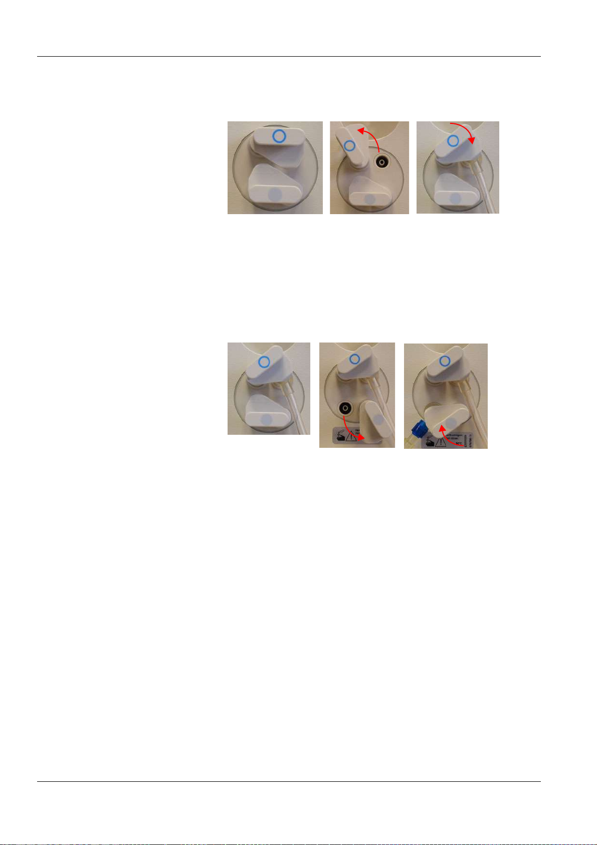
Chapter 5: Preparation
15 Connect the arterial patient access line to the SafeLine™.
b
a
c
16 To connect the substituate connector to the substituate port:
The catch for the substituate port (blue) is in initial position (a).
Pull and turn the substituate catch (blue) counterclockwise into
position (b).
Push the substituate connector firmly into the substituate port.
Pull and turn the substituate catch (blue) clockwise until it clicks into
place at position (c). If necessary to make sure of a tight closure
push in the substituate catch (blue).
a
b
c
17 To insert the rinse connector (connected onto the venous patient
line) into the rinse port:
The catch for the rinse port (grey) is in initial position (a).
Pull and turn the rinse port catch (grey) counterclockwise into
position (b).
Push the rinse connector firmly into the rinse port.
Pull and turn the rinse port catch (grey) clockwise until it clicks into
place at position (c). If necessary to make sure of a tight closure
push in the rinse port catch (grey).
Close the doors.
(The line segment(s) are automatically inserted, the arterial pressure
measurement unit closes.)
The system automatically switches to the PREPARATION SCREEN.
Message: Connect dialyzer couplings!
5-10 Fresenius Medical Care 5008 OP 5/09.06
Page 61

5.1.6 Connecting the Dialysate Lines
Note
The dialysate lines may only be connected after the T1 test has been
completely terminated.
Message: Connect dialyzer couplings!
Open the shunt door.
Connect the dialysate supply line (dialyzer coupling red) to the dialyzer
(on the side of the venous blood outlet port).
Connect the dialysate return line (dialyzer coupling blue) to the dialyzer
(on the side of the arterial blood inlet port).
Close the shunt door.
5.1.7 Priming the Extracorporeal Blood Circuit with ONLINEplus™
Chapter 5: Preparation
O Starting the Rinse procedure
PREPARATION SCREEN
Check/set the rinse volume.
Check/set the delivery rate of the blood pump.
The rinse volume and the delivery rate are automatically set to the value
preselected in the Operator Setup. Change the rinse volume and the
delivery rate if necessary.
Touch the Blood pump I/O button. (Blood pump I/O indicator green.)
O Interrupting the Rinse procedure
PREPARATION SCREEN
Touch the Blood pump I/O button. (Blood pump I/O indicator grey.)
Message: Do not connect patient! Minimum rinse volume not reached.
– Rinse Continue
If not yet done, the parameters for dialysate, UF and the
heparin pump now may be checked/set.
Touch the Continue button to continue rinsing. (Blood pump I/O
indicator green.)
Fresenius Medical Care 5008 OP 5/09.06 5-11
Page 62

Chapter 5: Preparation
O Rinse procedure completed
Endless rinse will start when the Online rinse volume and the Online UF
rinse volume have been reached.
The delivery rate of the blood pump is automatically reduced to
50 ml/min, and the dialysate flow is reduced to EcoFlow (100 ml/min).
In case of ONLINEplus™, the total flow is composed of EcoFlow
(100 ml/min) and the respective substituate rate.
5.1.8 Checking/Setting the Dialysate Parameters
Note
Calcium carbonate precipitations may occur in the bicarbonate dialysis,
depending on the use and the dose of the concentrates and the duration
of the treatment. Detailed information will be provided by the
manufacturer on request.
The Prescr. Bic can be reduced to 25.0 mmol/l during preparation
(adjustable in the Technician's Setup). If the Bic reduction is selected,
25.0 mmol/l appears below the value Prescr. Bic. The Bic reduction is
de-activated when the treatment starts.
After completion of the T1 test, the EcoFlow (100 ml/min) is
automatically selected. The flow can be changed as desired.
On the PREPARATION SCREEN you can directly check,
select and change the Prescr. Na and Prescr. Bic
parameters.
In the DIALYSATE MENU
Check the dialysate parameters.
Set the desired parameters. Touch the OK button to confirm the values
entered.
Visually check the confirmed values.
Touch the PREPARATION menu button to return to the
PREPARATION SCREEN.
5.1.9 Checking/Setting the UF Parameters
On the PREPARATION SCREEN you can directly check,
select and change the UF goal, UF time and UF rate
parameters.
5-12 Fresenius Medical Care 5008 OP 5/09.06
Page 63

Chapter 5: Preparation
Note
If only the UF rate is entered for ultrafiltration (instead of volume and
time), check the UF rate displayed in the Dialysis menu for plausibility
after saving the data.
In the UF MENU
Possible setting variants:
– UF goal/UF time (UF rate is calculated)
– UF goal/UF rate (UF time is calculated)
– UF rate/UF time
–UF rate
–Time
– UF profiles
– ISO goal/ISO time (ISO rate is calculated)
– ISO goal/ISO rate (ISO time is calculated)
The following must be observed in case of ISO-UF:
The ISO-UF treatment type can be started at any time and can be
repeated as often as necessary.
The parameters entered at the beginning of the treatment (UF goal and
UF time) must be taken into consideration.
In case of a combination with UF and Na profiles, first enter the ISO UF
parameters. Then set the respective profiles.
The total volume to be removed (UF goal), the total treatment time (UF
time) or the UF goal and the UF rate must always be programmed. The
ISO data goal and time cannot be higher than the UF goal/time.
The UF goal/UF time or UF goal/UF rate parameters must first be
entered.
Set the desired parameters.
Touch the OK button to confirm the entered values.
Visually check the confirmed values.
Touch the PREPARATION menu button to return to the
PREPARATION SCREEN.
5.1.10 Checking/Setting the Sodium and UF Profiles
Caution
When using Na profiles, the following precautions must be observed:
The balancing neutrality of the profiles was computed for a dialysis dose
of KT/V = 1.2. In case of higher deviations (KT/V > 1.4; KT/V < 1.0) the
balancing neutrality may not always be achieved.
Basic requirements for setting the profiles:
the UF parameters must have been set.
Fresenius Medical Care 5008 OP 5/09.06 5-13
Page 64

Chapter 5: Preparation
O Na profiles
In the DIALYSATE MENU
Check the dialysate parameters.
Minimum value that can be set for Start Na: 3 mmol higher than the
prescribed Na
Set the desired profile.
Check/set Start Na (maximum value).
(The minimum Na value is automatically adjusted.)
The following must be observed:
– The treatment may also be started with the Na profile only.
– It is only possible to select matching profile groups.
(E.g. if UF profile 1 has been selected, only Na profile 1 is available.)
– After having started the profiles, it is no longer possible to alter the
Concentrate, Prescr. Na and Prescr. Bic parameters.
– The minimum UF time must be set:
Profiles 1, 2: UF time 2:00 hrs
Profile 3: UF time 3:30 hrs
Set the desired parameters.
Touch the OK button to confirm the entered values.
Visually check the confirmed values.
O UF profiles
Touch the PREPARATION menu button to return to the
PREPARATION SCREEN.
In the UF MENU
Check the UF parameters.
Minimum UF parameters that can be set:
Profiles 1, 2: UF goal 200 ml, UF time 2:00 hrs, UF rate 10 ml
Profile 3: UF goal 200 ml, UF time 3:30 hrs, UF rate 10 ml
Set the desired profile.
Check/set the start rate.
(The minimum profile rate is automatically adjusted.)
The following must be observed:
– The treatment may also be started with the UF profile only.
– It is only possible to select matching profile groups.
(E.g. if Na profile 1 has been selected, only UF profile 1 is available.)
– After having started the profiles, it is no longer possible to alter the
UF time and UF rate parameters.
– ISO UF parameters and Na parameters may be selected only before
starting or after ending a profile.
Set the desired parameters.
Touch the OK button to confirm the entered values.
Visually check the confirmed values.
Touch the PREPARATION menu button to return to the
PREPARATION SCREEN.
5-14 Fresenius Medical Care 5008 OP 5/09.06
Page 65

5.1.11 Checking/Setting the Heparin Pump Parameters
Caution
Administer the heparin dose according to the physician's instructions.
In the HEPARIN menu
Check the heparin pump parameters.
Set the desired parameters. Touch the OK button to confirm the values
entered.
Visually check the confirmed values.
Touch the PREPARATION menu button to return to the
PREPARATION SCREEN.
Chapter 5: Preparation
Fresenius Medical Care 5008 OP 5/09.06 5-15
Page 66

Chapter 5: Preparation
5-16 Fresenius Medical Care 5008 OP 5/09.06
Page 67

5.2 Preparation with Rinse Solution Bag
If the 5008 ONLINEplus™ hemodialysis system cannot be operated
without rinse solution bags, rinse or infusion solutions provided in NaCl
bags may be used instead.
5.2.1 Turning the Hemodialysis System On
Caution
The stability of the 5008 hemodialysis system must be ensured.
Establish the water and power supply.
Press the On/Off key. (Turn the hemodialysis system on!)
The On/Off LED is illuminated.
START-UP SCREEN
Chapter 5: Preparation
The display shows the machine type, the current software version and
the clinical data (on request) for approx. 15 seconds.
Caution
After a downtime of more than 72 hours, a cleaning program must be
performed completely before starting the treatment.
If necessary, check the hemodialysis system for presence of residual
disinfectant. (see chapter 8 Cleaning).
Note
If the message: Defective battery is acknowledged by pressing the Skip
key, it might be that the audible alarm will not be generated, if a power
failure occurs.
Fresenius Medical Care 5008 OP 5/09.06 5-17
Page 68
Chapter 5: Preparation
5.2.2 The Following Must be Observed when Using Consumables
Caution
The system has been approved for use with the consumables and
accessories listed in the Operating Instructions.
Should the responsible organization wish to use other consumables
and accessories than those listed in the Operating Instructions, the
responsibility to ensure the correct function of the system lies
exclusively with the responsible organization. The applicable legal
regulations must be complied with (e.g. in Germany the Medical Device
Directive, MDD and the MPBetreibV = German regulation for the
operation of medical products).
The manufacturer does not assume any responsibility or liability for
personal injury or other damage and excludes any warranty for damage
to the system resulting from the use of non-approved or unsuitable
consumables or accessories.
Caution
The symbols printed on the packaging of the consumables have to be
observed. The symbols are described in the chapter System
Description (consumables symbols).
When using consumables, it is important to take note of the following
symbols:
Do not reuse
2
Use by
Caution
The consumables may only be used if the packaging and the respective
consumable including the protective caps used are not damaged. The
protective caps must not have fallen off.
The plastics used for the consumables may not be compatible with
components of drugs or disinfectants. If they are planned to be used,
the compatibility of the consumables' components must be ensured
before the treatment. If connectors made of polycarbonate are for
example exposed to aqueous solutions with the pH value > 10 or to
aliphatic solutions this will cause tension cracks.
5-18 Fresenius Medical Care 5008 OP 5/09.06
Page 69

5.2.3 Selecting the Concentrate Supply
O Connecting the concentrates
Caution
Concentrate:
The concentrate displayed on the screen must comply with the
specifications mentioned on the acid or the acetate container or on the
bag. This also applies to the concentrate composition in CDS operation.
Concentrate packages:
– Assure that the packages used contain sufficient concentrate to
complete the treatment.
– Use only the dedicated coded containers or the bibag
bicarbonate dialysis.
Bicarbonate dry concentrate bibag
Only the bibag
The bibag
Only use the bibag
concentrate according to the prescribed dilution. Other mixing ratios
may lead to a hazard for the patient.
Chapter 5: Preparation
®
®
®
manufactured by Fresenius Medical Care may be used.
®
must only be used for one treatment.
®
in combination with acid bicarbonate hemodialysis
:
for
Acid and basic bicarbonate hemodialysis concentrate have to be diluted
immediately prior to application only. The bag's content must be used
up within 12 hours after dilution. Discard residual volumes. The powder
is non-pyrogenic.
Conductivity limits:
The alarm limits are automatically set around the expected value.
The actual value of the conductivity display must have attained the
expected desired value after a maximum of 10 minutes.
Should this not be the case, the actual value must first be checked in
the laboratory. Change or check the concentrate, if necessary, or call
service.
Note
The bicarbonate suction tube must be inserted into the rinse chamber
during the bibag
®
treatment.
Extract the concentrate rack.
Bicarbonate dialysis To connect the (acid) concentrate container:
Push the latch (1) upwards. Open the concentrate flap. Place the red
concentrate suction tube (2) into the acid container. Close the
concentrate flap (3) until it clicks into place.
Fresenius Medical Care 5008 OP 5/09.06 5-19
Page 70

Chapter 5: Preparation
CDS, Central Delivery
System (option)
Acetate dialysis Connect the concentrate container.
To connect the bibag®:
Push the latch (1) upwards. Open the bicarbonate flap. Remove the
®
bibag
bibag
from its packaging. Remove the foil from the bibag®. Attach the
®
(2). Close the bicarbonate flap (3) until it clicks into place.
OR
To connect the bicarbonate container:
Insert the bicarbonate suction tube (blue) into the bicarbonate
container.
Close the bicarbonate flap.
Note
The responsible organization is responsible for the proper installation
and function of the CDS.
Insert the concentrate suction tube (red) into the acetate container.
The bicarbonate suction tube (blue) remains in the rinse chamber.
Selecting a treatment SELECTION SCREEN
Touch the Treatment field.
If there is no tubing system inserted, the system automatically moves to
the BLOOD SYSTEM screen.
BLOOD SYSTEM SCREEN
The T1 test is now running in parallel with the preparation of the
hemodialysis system. The color of the header bar is orange for the
duration of the T1 test.
The operating mode display shows the progress of the T1 test.
Message: T1 test completed is displayed for a moment after successful
completion of the T1 test.
5-20 Fresenius Medical Care 5008 OP 5/09.06
Page 71

Chapter 5: Preparation
5.2.4 Important Items to be Considered Before and During the Treatment
Caution
Aseptic technique:
Use aseptic technique for all bloodside connections and all connections
in the area where sterile solutions are to be used.
Caution
Preventing contamination:
Use tubing systems with hydrophobic filters at the pressure lines to
prevent cross-contamination.
Connect the hydrophobic filters so that an ingress or loss of air is not
possible and that any wetting by fluid is reliably avoided, also in case of
pressure fluctuations.
If a hydrophobic filter has become wet, the tubing system must be
replaced.
On tubing systems with additional connection sites, a replacement
pressure line may be connected (accessory available from Fresenius
Medical Care).
The blood in the pressure line must not be forced back by means of a
syringe. This could damage the hydrophobic membrane and thus lead
to a contamination.
If fluid may have passed the hydrophobic filter, the system must be
checked for contamination after completion of the treatment. If the
system is contaminated, it has to be taken out of service. All affected
components have to be disinfected or replaced in accordance with the
manufacturer's specifications before the system is put into operation
again.
Fresenius Medical Care 5008 OP 5/09.06 5-21
Page 72

Chapter 5: Preparation
Caution
When inserting the tubing systems, the following precautions
must be respected:
– The tubing systems have to be free of kinks, tension and twists and
must not be jammed (risk of hemolysis). Use the line holders
provided.
– Ensure the correct position of the screwed connections, especially
of the connection sites to the patient, the dialyzer and the system
and check or correct them during the treatment if necessary. Take
the appropriate measures if required (e.g. retightening of the Luer
Lock connection or replacement of the tubing system).
– Check the protective caps for tight fit and tighten them if necessary.
– The lines for the supply of infusions should always be clamped,
except if they are needed.
– During long-term operation, the blood lines must be changed after
24 hours at the latest.
– Do not use cannulas with a diameter of > 20 gauge to pierce the
septum of the injection sites. Insert the cannula vertically and in the
center of the septum. Disinfect the injection sites with 70% alcohol
before use.
– The blood pump must be set to the diameter of the pump segment,
refer also to the product label of the blood lines. If a wrong line
diameter is set, this may cause significant deviations in the blood
flow and thus in the dialysis dose.
– Materials which come directly or indirectly into contact with blood
are: Plasticized PVC, unplasticized PVC, polyethylene,
polycarbonate, latex-free rubber, ABS.
– The minimum temperature of the tubing systems during use is 18 °C.
Caution
Delivery operation of the pump(s) with open doors
(blood pump, substituate pump, optional Single-Needle pump):
When the doors are open and the rotor of the pump(s) is running, make
sure that no objects, such as fingers, hair or ball point pens, come into
contact with the rotor (risk of injury).
Arterial pressure measurement unit:
Prevent foreign objects from coming into contact with the arterial
pressure measurement unit.
Heparin pump:
If heparin syringes of third party suppliers are used, the operator is
responsible and has to ensure that the syringe data displayed match the
actual data.
Heparin syringes without Luer lock are not recommended as the
connection between the heparin syringe and the blood lines may come
loose. If heparin syringes without Luer lock are used it is the operator’s
responsibility to ensure that the connection between the heparin syringe
and the blood lines does not loosen inadvertently.
IV pole:
Securely fix bags or other objects to be hung from the IV pole.
5-22 Fresenius Medical Care 5008 OP 5/09.06
Page 73

Chapter 5: Preparation
Caution
Before the treatment, check:
– The safe connection of all connection sites of the tubing system.
– The tightness of the tubing system during and after priming.
– Retighten the connections and replace the tubing system, if
necessary.
– The absence of air in the tubing system and the correct position of
all fluid levels.
To be observed when working on the tubing system during the
treatment:
If the position of the tubing system or of one of its components is
changed, the correct position of the entire tubing system must be
restored afterwards, above all the correct position of the line guides.
During the treatment check at appropriate intervals:
– The condition of the patient.
– The function of the hemodialysis system and the extracorporeal
blood circuit. Pay particular attention to the venous insertion site, as
a possible dislocation of the venous cannula may not always be
detected by the pressure monitoring system.
– The tubing system for leakages or possible loosening of connections
as well as entry of air.
– The fluid level in the venous bubble catcher. Correct it, if required
(desired level: approx. 1 cm below the upper edge of the cover)
Caution
Venous alarm limit:
The lower venous alarm limit must be set as close as possible to the
actual venous pressure value.
Note
The dialyzer holder is not suitable for rectangular plate dialyzers.
Note
For hygienic reasons, the blood lines should be inserted immediately
prior to the treatment only.
If the blood lines were inserted more than 8 hours before the treatment,
malfunctions may occur. Correcting these malfunctions may require
removing the present blood lines and inserting new blood lines.
Fresenius Medical Care 5008 OP 5/09.06 5-23
Page 74
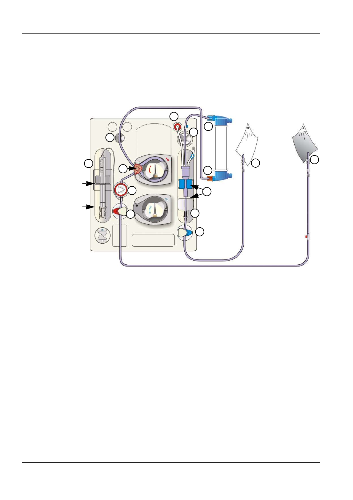
Chapter 5: Preparation
5.2.5 Preparing the Extracorporeal Blood Circuit with Rinse Solution Bag
O Inserting the arterial and the venous tubing system
When inserting the tubing system, follow the description of the menu
displayed.
13
12
2
11
Wings of the
syringe cylinder
Thumb rest of the
syringe plunger
7
1
4
5
3
8
9
10
14
6
Open the doors of the Extracorporeal Blood Module.
1 Insert the line guide into the blood pump until a signal is sounded.
The arterial pressure measurement unit is opened.
(After closing the doors the pump segment will be automatically
inserted into the blood pump.)
2 Insert the arterial blood line into the line holder.
3 Connect the arterial blood line to the lower port of the dialyzer.
4 Insert the arterial pressure dome into the arterial pressure
measurement unit.
5 Insert the arterial blood line into the arterial occlusion clamp.
6 Connect the arterial patient connection of the tubing system to the
rinse solution bag.
5-24 Fresenius Medical Care 5008 OP 5/09.06
Page 75

Chapter 5: Preparation
Caution
If no heparin syringe is used, retighten the cap of the heparin line and
close the clamp.
7 Connect the heparin syringe to the arterial tubing system.
To place the heparin syringe in the holder:
Press on the clamping brackets to move the grip handle to its lower
position.
Place the heparin syringe between the barrel holders.
The syringe wings must be positioned between the barrel holders
and the bracket.
The thumb rest of the syringe plunger now must be positioned
between the clamps of the grip handle.
Press on the clamping brackets to move the grip handle to its
starting position.
Caution
When inserting the heparin syringe, the following precautions must be
respected:
– Only use heparin syringes with a volume of up and equal to 30 ml.
– Ensure that the heparin syringe is correctly inserted into the heparin
pump and locked. Follow the description and the illustration.
8 Insert the venous bubble catcher into the level detector. Mind the
locator for the venous bubble catcher.
9 Insert the venous line into the optical detector/air bubble detector.
The line must be positioned completely inside the line housing.
Caution
The following must be observed for the air bubble detector:
– No ultrasound-conducting objects and agents may be used.
– The line housing must be clean and dry.
10 Insert the venous blood line into the venous occlusion clamp.
11 Insert the venous blood line into the line holder.
12 Connect the venous blood line to the upper port of the dialyzer.
13 Connect the venous pressure line to the venous pressure connector.
Caution
Tightly connect the hydrophobic filter of the venous pressure line to the
venous pressure connector in order to avoid an ingress or loss of air.
14 Connect the venous patient connection of the tubing system to the
prime collection bag. (Prime collection bag not included in scope of
delivery of the tubing system.)
Close the doors.
(The line segment(s) are automatically inserted, the arterial pressure
measurement unit closes.)
Break the cone on the rinse solution bag.
Fresenius Medical Care 5008 OP 5/09.06 5-25
Page 76

Chapter 5: Preparation
The system automatically switches to the PREPARATION SCREEN.
Message: Connect dialyzer couplings!
5.2.6 Connecting the Dialysate Lines
Note
The dialysate lines may only be connected after the T1 test has been
completely terminated.
Message: Connect dialyzer couplings!
Open the shunt door.
Connect the dialysate supply line (dialyzer coupling red) to the dialyzer
(on the side of the venous blood outlet port).
Connect the dialysate return line (dialyzer coupling blue) to the dialyzer
(on the side of the arterial blood inlet port).
Close the shunt door.
5.2.7 Priming the Extracorporeal Blood Circuit with Rinse Solution Bag
O Starting the Rinse procedure
PREPARATION SCREEN
Check/set the rinse volume.
Check/set the delivery rate of the blood pump.
The rinse volume and the delivery rate are automatically set to the value
preselected in the Operator Setup. Change the rinse volume and the
delivery rate if necessary.
Touch the Blood pump I/O button. (Blood pump I/O indicator green.)
If not yet done, the parameters for dialysate, UF and the
heparin pump now may be checked/set.
O Interrupting the Rinse procedure
PREPARATION SCREEN
Touch the Blood pump I/O button. (Blood pump I/O indicator grey.)
Message: Do not connect patient! Minimum rinse volume not reached.
– Rinse Continue
Do not connect a patient if rinsing is interrupted during the T1 test or
during a cleaning program.
5-26 Fresenius Medical Care 5008 OP 5/09.06
Page 77

Touch the Blood pump I/O button to continue the Rinse procedure.
(Blood pump I/O indicator green.)
O Rinse procedure completed
Message: Rinse volume reached. – Rinse Continue – Circulation Start
Mute LED is flashing. Audible signal
Connect the venous tubing system to the rinse solution bag.
Touch the Start button to launch precirculation. (Blood pump I/O
indicator green.)
O Interrupting the Circulation procedure
PREPARATION SCREEN
Touch the Blood pump I/O button. (Blood pump I/O indicator grey.)
If T1 test active:
Message: CAUTION! T1 test still in progress! Patient cannot be
connected!
Chapter 5: Preparation
Touch the Blood pump I/O button to continue the circulation
procedure. (Blood pump I/O indicator green.)
5.2.8 Checking/Setting the Dialysate Parameters
Note
Calcium carbonate precipitations may occur in the bicarbonate dialysis,
depending on the use and the dose of the concentrates and the duration
of the treatment. Detailed information will be provided by the
manufacturer on request.
The Prescr. Bic can be reduced to 25.0 mmol/l during preparation
(adjustable in the Technician's Setup). If the Bic reduction is selected,
25.0 mmol/l appears below the value Prescr. Bic. The Bic reduction is
de-activated when the treatment starts.
After completion of the T1 test, the EcoFlow (100 ml/min) is
automatically selected. The flow can be changed as desired.
On the PREPARATION SCREEN you can directly check,
select and change the Prescr. Na and Prescr. Bic
parameters.
In the DIALYSATE MENU
Check the dialysate parameters.
Set the desired parameters. Touch the OK button to confirm the values
entered.
Visually check the confirmed values.
Fresenius Medical Care 5008 OP 5/09.06 5-27
Page 78

Chapter 5: Preparation
Touch the PREPARATION menu button to return to the
PREPARATION SCREEN.
5.2.9 Checking/Setting the UF Parameters
On the PREPARATION SCREEN you can directly check,
select and change the UF goal, UF time and UF rate
parameters.
Note
If only the UF rate is entered for ultrafiltration (instead of volume and
time), check the UF rate displayed in the Dialysis menu for plausibility
after saving the data.
In the UF MENU
Possible setting variants:
– UF goal/UF time (UF rate is calculated)
– UF goal/UF rate (UF time is calculated)
– UF rate/UF time
–UF rate
–Time
– UF profiles
– ISO goal/ISO time (ISO rate is calculated)
– ISO goal/ISO rate (ISO time is calculated)
The following must be observed in case of ISO-UF:
The ISO-UF treatment type can be started at any time and can be
repeated as often as necessary.
The parameters entered at the beginning of the treatment (UF goal and
UF time) must be taken into consideration.
In case of a combination with UF and Na profiles, first enter the ISO UF
parameters. Then set the respective profiles.
The total volume to be removed (UF goal), the total treatment time (UF
time) or the UF goal and the UF rate must always be programmed. The
ISO data goal and time cannot be higher than the UF goal/time.
The UF goal/UF time or UF goal/UF rate parameters must first be
entered.
Set the desired parameters.
Touch the OK button to confirm the entered values.
Visually check the confirmed values.
Touch the PREPARATION menu button to return to the
PREPARATION SCREEN.
5-28 Fresenius Medical Care 5008 OP 5/09.06
Page 79

5.2.10 Checking/Setting the Sodium and UF Profiles
Caution
When using Na profiles, the following precautions must be observed:
The balancing neutrality of the profiles was computed for a dialysis dose
of KT/V = 1.2. In case of higher deviations (KT/V > 1.4; KT/V < 1.0) the
balancing neutrality may not always be achieved.
Basic requirements for setting the profiles:
the UF parameters must have been set.
O Na profiles
In the DIALYSATE MENU
Check the dialysate parameters.
Minimum value that can be set for Start Na: 3 mmol higher than the
prescribed Na
Chapter 5: Preparation
O UF profiles
Set the desired profile.
Check/set Start Na (maximum value).
(The minimum Na value is automatically adjusted.)
The following must be observed:
– The treatment may also be started with the Na profile only.
– It is only possible to select matching profile groups.
(E.g. if UF profile 1 has been selected, only Na profile 1 is available.)
– After having started the profiles, it is no longer possible to alter the
Concentrate, Prescr. Na and Prescr. Bic parameters.
– The minimum UF time must be set:
Profiles 1, 2: UF time 2:00 hrs
Profile 3: UF time 3:30 hrs
Set the desired parameters.
Touch the OK button to confirm the entered values.
Visually check the confirmed values.
Touch the PREPARATION menu button to return to the
PREPARATION SCREEN.
In the UF MENU
Check the UF parameters.
Minimum UF parameters that can be set:
Profiles 1, 2: UF goal 200 ml, UF time 2:00 hrs, UF rate 10 ml
Profile 3: UF goal 200 ml, UF time 3:30 hrs, UF rate 10 ml
Set the desired profile.
Check/set the start rate.
(The minimum profile rate is automatically adjusted.)
Fresenius Medical Care 5008 OP 5/09.06 5-29
Page 80

Chapter 5: Preparation
The following must be observed:
– The treatment may also be started with the UF profile only.
– It is only possible to select matching profile groups.
(E.g. if Na profile 1 has been selected, only UF profile 1 is available.)
– After having started the profiles, it is no longer possible to alter the
UF time and UF rate parameters.
– ISO UF parameters and Na parameters may be selected only before
starting or after ending a profile.
Set the desired parameters.
Touch the OK button to confirm the entered values.
Visually check the confirmed values.
Touch the PREPARATION menu button to return to the
PREPARATION SCREEN.
5.2.11 Checking/Setting the Heparin Pump Parameters
Caution
Administer the heparin dose according to the physician's instructions.
In the HEPARIN menu
Check the heparin pump parameters.
Set the desired parameters. Touch the OK button to confirm the values
entered.
Visually check the confirmed values.
Touch the PREPARATION menu button to return to the
PREPARATION SCREEN.
5-30 Fresenius Medical Care 5008 OP 5/09.06
Page 81

Chapter 5: Preparation
5.3 Single-Needle (Option) Preparation Using ONLINEplus™
Irrespective of the treatment mode, all 5008 ONLINEplus™
hemodialysis systems can be operated without rinse or infusion
solutions provided in NaCl bags. The fluid volumes required for
preparation, bolus administration or during reinfusion will then be
produced ONLINE by the 5008 hemodialysis system according to the
actual requirements, thus saving both cost and time.
5.3.1 Turning the Hemodialysis System On
Caution
The stability of the 5008 hemodialysis system must be ensured.
Establish the water and power supply.
Press the On/Off key. (Turn the hemodialysis system on!)
The On/Off LED is illuminated.
START-UP SCREEN
The display shows the machine type, the current software version and
the clinical data (on request) for approx. 15 seconds.
Caution
After a downtime of more than 72 hours, a cleaning program must be
performed completely before starting the treatment.
If necessary, check the hemodialysis system for presence of residual
disinfectant. (see chapter 8 Cleaning).
Note
If the message: Defective battery is acknowledged by pressing the Skip
key, it might be that the audible alarm will not be generated, if a power
failure occurs.
Fresenius Medical Care 5008 OP 5/09.06 5-31
Page 82

Chapter 5: Preparation
5.3.2 The Following Must be Observed when Using Consumables
Caution
The system has been approved for use with the consumables and
accessories listed in the Operating Instructions.
Should the responsible organization wish to use other consumables
and accessories than those listed in the Operating Instructions, the
responsibility to ensure the correct function of the system lies
exclusively with the responsible organization. The applicable legal
regulations must be complied with (e.g. in Germany the Medical Device
Directive, MDD and the MPBetreibV = German regulation for the
operation of medical products).
The manufacturer does not assume any responsibility or liability for
personal injury or other damage and excludes any warranty for damage
to the system resulting from the use of non-approved or unsuitable
consumables or accessories.
Caution
The symbols printed on the packaging of the consumables have to be
observed. The symbols are described in the chapter System
Description (consumables symbols).
When using consumables, it is important to take note of the following
symbols:
Do not reuse
2
Use by
Caution
The consumables may only be used if the packaging and the respective
consumable including the protective caps used are not damaged. The
protective caps must not have fallen off.
The plastics used for the consumables may not be compatible with
components of drugs or disinfectants. If they are planned to be used,
the compatibility of the consumables' components must be ensured
before the treatment. If connectors made of polycarbonate are for
example exposed to aqueous solutions with the pH value > 10 or to
aliphatic solutions this will cause tension cracks.
5-32 Fresenius Medical Care 5008 OP 5/09.06
Page 83

5.3.3 Selecting the Concentrate Supply
O Connecting the concentrates
Caution
Concentrate:
The concentrate displayed on the screen must comply with the
specifications mentioned on the acid or the acetate container or on the
bag. This also applies to the concentrate composition in CDS operation.
Concentrate packages:
– Assure that the packages used contain sufficient concentrate to
complete the treatment.
– Use only the dedicated coded containers or the bibag
bicarbonate dialysis.
Bicarbonate dry concentrate bibag
Only the bibag
The bibag
Only use the bibag
concentrate according to the prescribed dilution. Other mixing ratios
may lead to a hazard for the patient.
Chapter 5: Preparation
®
®
®
manufactured by Fresenius Medical Care may be used.
®
must only be used for one treatment.
®
in combination with acid bicarbonate hemodialysis
:
for
Acid and basic bicarbonate hemodialysis concentrate have to be diluted
immediately prior to application only. The bag's content must be used
up within 12 hours after dilution. Discard residual volumes. The powder
is non-pyrogenic.
Conductivity limits:
The alarm limits are automatically set around the expected value.
The actual value of the conductivity display must have attained the
expected desired value after a maximum of 10 minutes.
Should this not be the case, the actual value must first be checked in
the laboratory. Change or check the concentrate, if necessary, or call
service.
Note
The bicarbonate suction tube must be inserted into the rinse chamber
during the bibag
®
treatment.
Extract the concentrate rack.
Bicarbonate dialysis To connect the (acid) concentrate container:
Push the latch (1) upwards. Open the concentrate flap. Place the red
concentrate suction tube (2) into the acid container. Close the
concentrate flap (3) until it clicks into place.
Fresenius Medical Care 5008 OP 5/09.06 5-33
Page 84

Chapter 5: Preparation
CDS, Central Delivery
System (option)
Acetate dialysis Connect the concentrate container.
To connect the bibag®:
Push the latch (1) upwards. Open the bicarbonate flap. Remove the
®
bibag
bibag
from its packaging. Remove the foil from the bibag®. Attach the
®
(2). Close the bicarbonate flap (3) until it clicks into place.
OR
To connect the bicarbonate container:
Insert the bicarbonate suction tube (blue) into the bicarbonate
container.
Close the bicarbonate flap.
Note
The responsible organization is responsible for the proper installation
and function of the CDS.
Insert the concentrate suction tube (red) into the acetate container.
The bicarbonate suction tube (blue) remains in the rinse chamber.
Selecting a treatment SELECTION SCREEN
Touch the Treatment field.
If there is no tubing system inserted, the system automatically moves to
the BLOOD SYSTEM screen.
BLOOD SYSTEM SCREEN
The T1 test is now running in parallel with the preparation of the
hemodialysis system. The color of the header bar is orange for the
duration of the T1 test.
The operating mode display shows the progress of the T1 test.
Message: T1 test completed is displayed for a moment after successful
completion of the T1 test.
5-34 Fresenius Medical Care 5008 OP 5/09.06
Page 85

Chapter 5: Preparation
5.3.4 Important Items to be Considered Before and During the Treatment
Caution
Aseptic technique:
Use aseptic technique for all bloodside connections and all connections
in the area where sterile solutions are to be used.
Caution
Preventing contamination:
Use tubing systems with hydrophobic filters at the pressure lines to
prevent cross-contamination.
Connect the hydrophobic filters so that an ingress or loss of air is not
possible and that any wetting by fluid is reliably avoided, also in case of
pressure fluctuations.
If a hydrophobic filter has become wet, the tubing system must be
replaced.
On tubing systems with additional connection sites, a replacement
pressure line may be connected (accessory available from Fresenius
Medical Care).
The blood in the pressure line must not be forced back by means of a
syringe. This could damage the hydrophobic membrane and thus lead
to a contamination.
If fluid may have passed the hydrophobic filter, the system must be
checked for contamination after completion of the treatment. If the
system is contaminated, it has to be taken out of service. All affected
components have to be disinfected or replaced in accordance with the
manufacturer's specifications before the system is put into operation
again.
Fresenius Medical Care 5008 OP 5/09.06 5-35
Page 86

Chapter 5: Preparation
Caution
When inserting the tubing systems, the following precautions
must be respected:
– The tubing systems have to be free of kinks, tension and twists and
must not be jammed (risk of hemolysis). Use the line holders
provided.
– Ensure the correct position of the screwed connections, especially
of the connection sites to the patient, the dialyzer and the system
and check or correct them during the treatment if necessary. Take
the appropriate measures if required (e.g. retightening of the Luer
Lock connection or replacement of the tubing system).
– Check the protective caps for tight fit and tighten them if necessary.
– The lines for the supply of infusions should always be clamped,
except if they are needed.
– During long-term operation, the blood lines must be changed after
24 hours at the latest.
– Do not use cannulas with a diameter of > 20 gauge to pierce the
septum of the injection sites. Insert the cannula vertically and in the
center of the septum. Disinfect the injection sites with 70% alcohol
before use.
– The blood pump must be set to the diameter of the pump segment,
refer also to the product label of the blood lines. If a wrong line
diameter is set, this may cause significant deviations in the blood
flow and thus in the dialysis dose.
– Materials which come directly or indirectly into contact with blood
are: Plasticized PVC, unplasticized PVC, polyethylene,
polycarbonate, latex-free rubber, ABS.
– The minimum temperature of the tubing systems during use is 18 °C.
Caution
Delivery operation of the pump(s) with open doors
(blood pump, substituate pump, optional Single-Needle pump):
When the doors are open and the rotor of the pump(s) is running, make
sure that no objects, such as fingers, hair or ball point pens, come into
contact with the rotor (risk of injury).
Arterial pressure measurement unit:
Prevent foreign objects from coming into contact with the arterial
pressure measurement unit.
Heparin pump:
If heparin syringes of third party suppliers are used, the operator is
responsible and has to ensure that the syringe data displayed match the
actual data.
Heparin syringes without Luer lock are not recommended as the
connection between the heparin syringe and the blood lines may come
loose. If heparin syringes without Luer lock are used it is the operator’s
responsibility to ensure that the connection between the heparin syringe
and the blood lines does not loosen inadvertently.
IV pole:
Securely fix bags or other objects to be hung from the IV pole.
5-36 Fresenius Medical Care 5008 OP 5/09.06
Page 87

Chapter 5: Preparation
Caution
Before the treatment, check:
– The safe connection of all connection sites of the tubing system.
– The tightness of the tubing system during and after priming.
– Retighten the connections and replace the tubing system, if
necessary.
– The absence of air in the tubing system and the correct position of
all fluid levels.
To be observed when working on the tubing system during the
treatment:
If the position of the tubing system or of one of its components is
changed, the correct position of the entire tubing system must be
restored afterwards, above all the correct position of the line guides.
During the treatment check at appropriate intervals:
– The condition of the patient.
– The function of the hemodialysis system and the extracorporeal
blood circuit. Pay particular attention to the venous insertion site, as
a possible dislocation of the venous cannula may not always be
detected by the pressure monitoring system.
– The tubing system for leakages or possible loosening of connections
as well as entry of air.
– The fluid level in the venous bubble catcher. Correct it, if required
(desired level: approx. 1 cm below the upper edge of the cover)
Caution
Venous alarm limit:
The lower venous alarm limit must be set as close as possible to the
actual venous pressure value.
Note
The dialyzer holder is not suitable for rectangular plate dialyzers.
Note
For hygienic reasons, the blood lines should be inserted immediately
prior to the treatment only.
If the blood lines were inserted more than 8 hours before the treatment,
malfunctions may occur. Correcting these malfunctions may require
removing the present blood lines and inserting new blood lines.
Fresenius Medical Care 5008 OP 5/09.06 5-37
Page 88
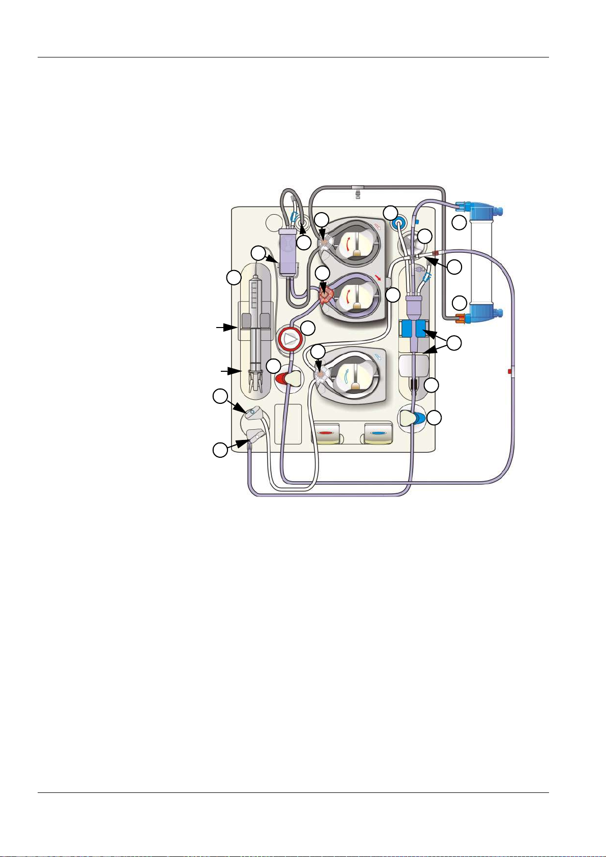
Chapter 5: Preparation
5.3.5 Preparing the Extracorporeal Blood Circuit with ONLINEplus™
O Inserting the arterial and the venous tubing system
When inserting the tubing system, follow the description of the menu
displayed.
Wings of the
syringe cylinder
Thumb rest of the
syringe plunger
18
19
4
2
3
8
7
1
6
15
14
16
13
12
17
5
9
10
11
Open the doors of the Extracorporeal Blood Module.
1 Insert the line guide into the blood pump until a signal is sounded.
The arterial pressure measurement unit is opened.
(After closing the doors the pump segment will be automatically
inserted into the blood pump.)
2 Connect the SN pressure line to the Single-Needle pressure port.
3 Insert the SN chamber in its holder.
4 Insert the SN line guide into the Single-Needle pump until a signal is
sounded.
(After closing the doors the SN pump segment is automatically
inserted in the Single-Needle pump, if the level detector detected
fluid.)
5 Connect the arterial blood line to the lower port of the dialyzer.
6 Insert the arterial pressure dome into the arterial pressure
measurement unit.
7 Insert the arterial blood line into the arterial occlusion clamp.
5-38 Fresenius Medical Care 5008 OP 5/09.06
Page 89

Chapter 5: Preparation
Caution
If no heparin syringe is used, retighten the cap of the heparin line and
close the clamp.
8 Connect the heparin syringe to the arterial tubing system.
To place the heparin syringe in the holder:
Press on the clamping brackets to move the grip handle to its lower
position.
Place the heparin syringe between the barrel holders.
The syringe wings must be positioned between the barrel holders
and the bracket.
The thumb rest of the syringe plunger now must be positioned
between the clamps of the grip handle.
Press on the clamping brackets to move the grip handle to its
starting position.
Caution
When inserting the heparin syringe, the following precautions must be
respected:
– Only use heparin syringes with a volume of up and equal to 30 ml.
– Ensure that the heparin syringe is correctly inserted into the heparin
pump and locked. Follow the description and the illustration.
9 Insert the venous bubble catcher into the level detector. Mind the
locator for the venous bubble catcher.
10 Insert the venous line into the optical detector/air bubble detector.
The line must be positioned completely inside the line housing.
Caution
The following must be observed for the air bubble detector:
– No ultrasound-conducting objects and agents may be used.
– The line housing must be clean and dry.
11 Insert the venous blood line into the venous occlusion clamp.
12 Insert the venous blood line into the line holder.
13 Connect the venous blood line to the upper port of the dialyzer.
14 Connect the venous pressure line to the venous pressure connector.
Caution
Tightly connect the hydrophobic filter of the venous pressure line to the
venous pressure connector in order to avoid an ingress or loss of air.
Inserting the lines may be continued only after successful completion of
the T1 test.
15 Insert the SafeLine™ line guide into the substituate pump until a
signal is sounded.
(After closing the doors the SafeLine™ pump segment will be
automatically inserted into the substituate pump.)
16 Insert the SafeLine™ into the line holder.
Fresenius Medical Care 5008 OP 5/09.06 5-39
Page 90

Chapter 5: Preparation
17 Connect the arterial patient access line to the SafeLine™.
b
a
c
18 To connect the substituate connector to the substituate port:
The catch for the substituate port (blue) is in initial position (a).
Pull and turn the substituate catch (blue) counterclockwise into
position (b).
Push the substituate connector firmly into the substituate port.
Pull and turn the substituate catch (blue) clockwise until it clicks into
place at position (c). If necessary to make sure of a tight closure
push in the substituate catch (blue).
a
b
c
19 To insert the rinse connector (connected onto the venous patient
line) into the rinse port:
The catch for the rinse port (grey) is in initial position (a).
Pull and turn the rinse port catch (grey) counterclockwise into
position (b).
Push the rinse connector firmly into the rinse port.
Pull and turn the rinse port catch (grey) clockwise until it clicks into
place at position (c). If necessary to make sure of a tight closure
push in the rinse port catch (grey).
Close the doors.
(The line segment(s) are automatically inserted, the arterial pressure
measurement unit closes.)
The system automatically switches to the PREPARATION SCREEN.
Message: Connect dialyzer couplings!
5-40 Fresenius Medical Care 5008 OP 5/09.06
Page 91

5.3.6 Connecting the Dialysate Lines
Note
The dialysate lines may only be connected after the T1 test has been
completely terminated.
Message: Connect dialyzer couplings!
Open the shunt door.
Connect the dialysate supply line (dialyzer coupling red) to the dialyzer
(on the side of the venous blood outlet port).
Connect the dialysate return line (dialyzer coupling blue) to the dialyzer
(on the side of the arterial blood inlet port).
Close the shunt door.
5.3.7 Priming the Extracorporeal Blood Circuit with ONLINEplus™
Chapter 5: Preparation
O Starting the Rinse procedure
PREPARATION SCREEN
Check/set the rinse volume.
Check/set the delivery rate of the blood pump.
The rinse volume and the delivery rate are automatically set to the value
preselected in the Operator Setup. Change the rinse volume and the
delivery rate if necessary.
Touch the Blood pump I/O button. (Blood pump I/O indicator green.)
O Interrupting the Rinse procedure
PREPARATION SCREEN
Touch the Blood pump I/O button. (Blood pump I/O indicator grey.)
Message: Do not connect patient! Minimum rinse volume not reached.
– Rinse Continue
If not yet done, the parameters for dialysate, UF and the
heparin pump now may be checked/set.
Touch the Continue button to continue rinsing. (Blood pump I/O
indicator green.)
Fresenius Medical Care 5008 OP 5/09.06 5-41
Page 92

Chapter 5: Preparation
O Rinse procedure completed
Endless rinse will start when the Online rinse volume and the Online UF
rinse volume have been reached.
The delivery rate of the blood pump is automatically reduced to
50 ml/min, and the dialysate flow is reduced to EcoFlow (100 ml/min).
In case of ONLINEplus™, the total flow is composed of EcoFlow
(100 ml/min) and the respective substituate rate.
5.3.8 Checking/Setting the Dialysate Parameters
Note
Calcium carbonate precipitations may occur in the bicarbonate dialysis,
depending on the use and the dose of the concentrates and the duration
of the treatment. Detailed information will be provided by the
manufacturer on request.
The Prescr. Bic can be reduced to 25.0 mmol/l during preparation
(adjustable in the Technician's Setup). If the Bic reduction is selected,
25.0 mmol/l appears below the value Prescr. Bic. The Bic reduction is
de-activated when the treatment starts.
After completion of the T1 test, the EcoFlow (100 ml/min) is
automatically selected. The flow can be changed as desired.
On the PREPARATION SCREEN you can directly check,
select and change the Prescr. Na and Prescr. Bic
parameters.
In the DIALYSATE MENU
Check the dialysate parameters.
Set the desired parameters. Touch the OK button to confirm the values
entered.
Visually check the confirmed values.
Touch the PREPARATION menu button to return to the
PREPARATION SCREEN.
5.3.9 Checking/Setting the UF Parameters
On the PREPARATION SCREEN you can directly check,
select and change the UF goal, UF time and UF rate
parameters.
5-42 Fresenius Medical Care 5008 OP 5/09.06
Page 93

Chapter 5: Preparation
Note
If only the UF rate is entered for ultrafiltration (instead of volume and
time), check the UF rate displayed in the Dialysis menu for plausibility
after saving the data.
In the UF MENU
Possible setting variants:
– UF goal/UF time (UF rate is calculated)
– UF goal/UF rate (UF time is calculated)
– UF rate/UF time
–UF rate
–Time
– UF profiles
– ISO goal/ISO time (ISO rate is calculated)
– ISO goal/ISO rate (ISO time is calculated)
The following must be observed in case of ISO-UF:
The ISO-UF treatment type can be started at any time and can be
repeated as often as necessary.
The parameters entered at the beginning of the treatment (UF goal and
UF time) must be taken into consideration.
In case of a combination with UF and Na profiles, first enter the ISO UF
parameters. Then set the respective profiles.
The total volume to be removed (UF goal), the total treatment time (UF
time) or the UF goal and the UF rate must always be programmed. The
ISO data goal and time cannot be higher than the UF goal/time.
The UF goal/UF time or UF goal/UF rate parameters must first be
entered.
Set the desired parameters.
Touch the OK button to confirm the entered values.
Visually check the confirmed values.
Touch the PREPARATION menu button to return to the
PREPARATION SCREEN.
5.3.10 Checking/Setting the Sodium and UF Profiles
Caution
When using Na profiles, the following precautions must be observed:
The balancing neutrality of the profiles was computed for a dialysis dose
of KT/V = 1.2. In case of higher deviations (KT/V > 1.4; KT/V < 1.0) the
balancing neutrality may not always be achieved.
Basic requirements for setting the profiles:
the UF parameters must have been set.
Fresenius Medical Care 5008 OP 5/09.06 5-43
Page 94

Chapter 5: Preparation
O Na profiles
In the DIALYSATE MENU
Check the dialysate parameters.
Minimum value that can be set for Start Na: 3 mmol higher than the
prescribed Na
Set the desired profile.
Check/set Start Na (maximum value).
(The minimum Na value is automatically adjusted.)
The following must be observed:
– The treatment may also be started with the Na profile only.
– It is only possible to select matching profile groups.
(E.g. if UF profile 1 has been selected, only Na profile 1 is available.)
– After having started the profiles, it is no longer possible to alter the
Concentrate, Prescr. Na and Prescr. Bic parameters.
– The minimum UF time must be set:
Profiles 1, 2: UF time 2:00 hrs
Profile 3: UF time 3:30 hrs
Set the desired parameters.
Touch the OK button to confirm the entered values.
Visually check the confirmed values.
O UF profiles
Touch the PREPARATION menu button to return to the
PREPARATION SCREEN.
In the UF MENU
Check the UF parameters.
Minimum UF parameters that can be set:
Profiles 1, 2: UF goal 200 ml, UF time 2:00 hrs, UF rate 10 ml
Profile 3: UF goal 200 ml, UF time 3:30 hrs, UF rate 10 ml
Set the desired profile.
Check/set the start rate.
(The minimum profile rate is automatically adjusted.)
The following must be observed:
– The treatment may also be started with the UF profile only.
– It is only possible to select matching profile groups.
(E.g. if Na profile 1 has been selected, only UF profile 1 is available.)
– After having started the profiles, it is no longer possible to alter the
UF time and UF rate parameters.
– ISO UF parameters and Na parameters may be selected only before
starting or after ending a profile.
Set the desired parameters.
Touch the OK button to confirm the entered values.
Visually check the confirmed values.
Touch the PREPARATION menu button to return to the
PREPARATION SCREEN.
5-44 Fresenius Medical Care 5008 OP 5/09.06
Page 95

5.3.11 Checking/Setting the Heparin Pump Parameters
Caution
Administer the heparin dose according to the physician's instructions.
In the HEPARIN menu
Check the heparin pump parameters.
Set the desired parameters. Touch the OK button to confirm the values
entered.
Visually check the confirmed values.
Touch the PREPARATION menu button to return to the
PREPARATION SCREEN.
5.3.12 Checking/Setting the Single-Needle Parameters
In the SINGLE-NEEDLE menu
Chapter 5: Preparation
Check the Single-Needle parameters.
Set the desired parameters. Touch the OK button to confirm the values
entered.
Visually check the confirmed values.
Touch the PREPARATION menu button to return to the
PREPARATION SCREEN.
Fresenius Medical Care 5008 OP 5/09.06 5-45
Page 96

Chapter 5: Preparation
5-46 Fresenius Medical Care 5008 OP 5/09.06
Page 97

Chapter 5: Preparation
5.4 Single-Needle (Option) Preparation with Rinse Solution Bag
If the 5008 ONLINEplus™ hemodialysis system cannot be operated
without rinse solution bags, rinse or infusion solutions provided in NaCl
bags may be used instead.
5.4.1 Turning the Hemodialysis System On
Caution
The stability of the 5008 hemodialysis system must be ensured.
Establish the water and power supply.
Press the On/Off key. (Turn the hemodialysis system on!)
The On/Off LED is illuminated.
START-UP SCREEN
The display shows the machine type, the current software version and
the clinical data (on request) for approx. 15 seconds.
Caution
After a downtime of more than 72 hours, a cleaning program must be
performed completely before starting the treatment.
If necessary, check the hemodialysis system for presence of residual
disinfectant. (see chapter 8 Cleaning).
Note
If the message: Defective battery is acknowledged by pressing the Skip
key, it might be that the audible alarm will not be generated, if a power
failure occurs.
Fresenius Medical Care 5008 OP 5/09.06 5-47
Page 98

Chapter 5: Preparation
5.4.2 The Following Must be Observed when Using Consumables
Caution
The system has been approved for use with the consumables and
accessories listed in the Operating Instructions.
Should the responsible organization wish to use other consumables
and accessories than those listed in the Operating Instructions, the
responsibility to ensure the correct function of the system lies
exclusively with the responsible organization. The applicable legal
regulations must be complied with (e.g. in Germany the Medical Device
Directive, MDD and the MPBetreibV = German regulation for the
operation of medical products).
The manufacturer does not assume any responsibility or liability for
personal injury or other damage and excludes any warranty for damage
to the system resulting from the use of non-approved or unsuitable
consumables or accessories.
Caution
The symbols printed on the packaging of the consumables have to be
observed. The symbols are described in the chapter System
Description (consumables symbols).
When using consumables, it is important to take note of the following
symbols:
Do not reuse
2
Use by
Caution
The consumables may only be used if the packaging and the respective
consumable including the protective caps used are not damaged. The
protective caps must not have fallen off.
The plastics used for the consumables may not be compatible with
components of drugs or disinfectants. If they are planned to be used,
the compatibility of the consumables' components must be ensured
before the treatment. If connectors made of polycarbonate are for
example exposed to aqueous solutions with the pH value > 10 or to
aliphatic solutions this will cause tension cracks.
5-48 Fresenius Medical Care 5008 OP 5/09.06
Page 99

5.4.3 Selecting the Concentrate Supply
O Connecting the concentrates
Caution
Concentrate:
The concentrate displayed on the screen must comply with the
specifications mentioned on the acid or the acetate container or on the
bag. This also applies to the concentrate composition in CDS operation.
Concentrate packages:
– Assure that the packages used contain sufficient concentrate to
complete the treatment.
– Use only the dedicated coded containers or the bibag
bicarbonate dialysis.
Bicarbonate dry concentrate bibag
Only the bibag
The bibag
Only use the bibag
concentrate according to the prescribed dilution. Other mixing ratios
may lead to a hazard for the patient.
Chapter 5: Preparation
®
®
®
manufactured by Fresenius Medical Care may be used.
®
must only be used for one treatment.
®
in combination with acid bicarbonate hemodialysis
:
for
Acid and basic bicarbonate hemodialysis concentrate have to be diluted
immediately prior to application only. The bag's content must be used
up within 12 hours after dilution. Discard residual volumes. The powder
is non-pyrogenic.
Conductivity limits:
The alarm limits are automatically set around the expected value.
The actual value of the conductivity display must have attained the
expected desired value after a maximum of 10 minutes.
Should this not be the case, the actual value must first be checked in
the laboratory. Change or check the concentrate, if necessary, or call
service.
Note
The bicarbonate suction tube must be inserted into the rinse chamber
during the bibag
®
treatment.
Extract the concentrate rack.
Bicarbonate dialysis To connect the (acid) concentrate container:
Push the latch (1) upwards. Open the concentrate flap. Place the red
concentrate suction tube (2) into the acid container. Close the
concentrate flap (3) until it clicks into place.
Fresenius Medical Care 5008 OP 5/09.06 5-49
Page 100

Chapter 5: Preparation
CDS, Central Delivery
System (option)
Acetate dialysis Connect the concentrate container.
To connect the bibag®:
Push the latch (1) upwards. Open the bicarbonate flap. Remove the
®
bibag
bibag
from its packaging. Remove the foil from the bibag®. Attach the
®
(2). Close the bicarbonate flap (3) until it clicks into place.
OR
To connect the bicarbonate container:
Insert the bicarbonate suction tube (blue) into the bicarbonate
container.
Close the bicarbonate flap.
Note
The responsible organization is responsible for the proper installation
and function of the CDS.
Insert the concentrate suction tube (red) into the acetate container.
The bicarbonate suction tube (blue) remains in the rinse chamber.
Selecting a treatment SELECTION SCREEN
Touch the Treatment field.
If there is no tubing system inserted, the system automatically moves to
the BLOOD SYSTEM screen.
BLOOD SYSTEM SCREEN
The T1 test is now running in parallel with the preparation of the
hemodialysis system. The color of the header bar is orange for the
duration of the T1 test.
The operating mode display shows the progress of the T1 test.
Message: T1 test completed is displayed for a moment after successful
completion of the T1 test.
5-50 Fresenius Medical Care 5008 OP 5/09.06
 Loading...