

Page 1
Service Manual
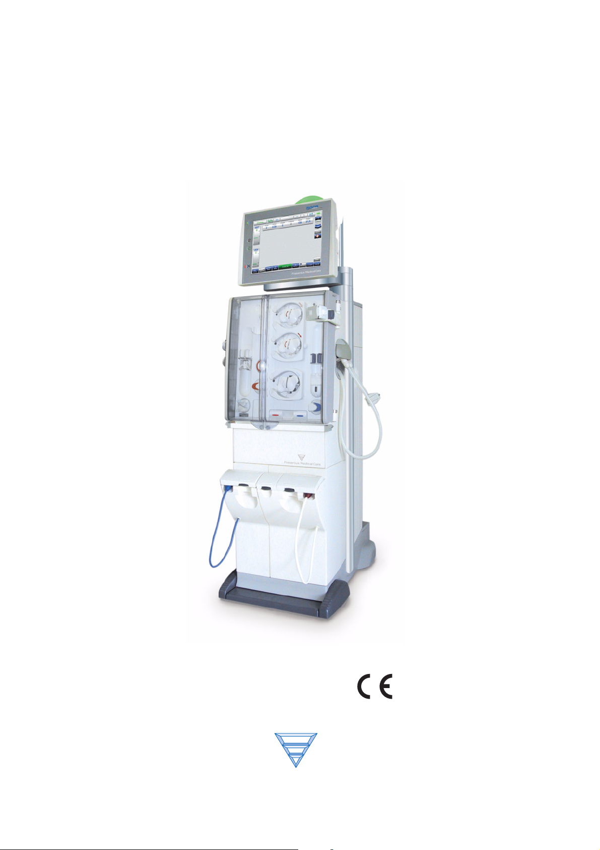
Hemodialysis System
5008
Edition: 1/08.04
Part number: M35 179 1
Fresenius
Medical
0123
Care
Page 2

Page 3

Table of Contents
1Index
2 Important Information
2.1 Organization of the Technical Document................................................................................ 2-1
2.2 How to Use the Technical Document ...................................................................................... 2-1
2.3 Precautions for Working on the System ................................................................................. 2-2
2.4 Addresses .................................................................................................................................. 2-2
3 Specifications
Page
4 Installation
4.1 Preface........................................................................................................................................ 4-1
4.2 Important Information on Initial Start-Up ................................................................................ 4-1
4.3 Initial Start-Up Report ............................................................................................................... 4-2
4.4 Explanations on the Initial Start-Up Report ............................................................................ 4-9
5Setup
5.1 Operator Setup .......................................................................................................................... 5-1
5.2 Technician's SETUP ................................................................................................................ 5-13
5.3 Information Regarding the Setting of Concentrates in the Technician’s Setup................ 5-21
6 TSC / TMC / Maintenance
6.1 Important Information ............................................................................................................... 6-1
6.2 Test Report – Technical Safety Checks, Technical Measurements Checks and Maintenance
Procedures6-3
6.3 Explanations on Technical Safety Checks, Technical Measurement Checks and
Maintenance Procedures6-11
6.4 TSC / TMC Report .................................................................................................................... 6-27
Fresenius Medical Care 5008 SM 1/08.04 i
Page 4

Kapitel :
7 Error Messages
8 Tools (Service Equipment)
9 Calibration / Adjustment
10 Repair
11 Functional Description
11.1 Overall System......................................................................................................................... 11-1
11.2 Overview of P.C.B.s................................................................................................................. 11-3
11.3 Monitor...................................................................................................................................... 11-4
11.4 EBM (Extracorporeal Blood Module) ..................................................................................... 11-6
11.5 Hydraulics Unit ........................................................................................................................ 11-8
11.6 Power Supply Unit................................................................................................................. 11-10
11.7 Pneumatic Unit....................................................................................................................... 11-12
11.8 Hydraulics Unit ...................................................................................................................... 11-14
12 Service Program (Option)
ii Fresenius Medical Care 5008 SM 1/08.04
Page 5

1 Index
How to use the index: E.g., index entry 1-3 is to be interpreted as: Chapter 1, page 3
Chapter 1: Index
A
Addresses 2-2
Alarm processing 5-4
AutoFlow 3-6
B
Blood pump 5-1
BPM 5-10
BTM 5-11
C
Concentrates 3-6
D
DIASAFE®plus 3-8
E
EcoFlow 3-6
Emergency 5-8
External connections 3-3
R
Reinfusion 5-2
T
Temperature 3-6
U
Ultrafiltration 5-3
User interface 5-5
F
Flow diagram 11-14
H
Heparin pump 3-8
O
OCM 3-9, 5-9
ONLINEplus™ 5-9
Operating programs 3-4
Operator Setup 5-1
Optical detector 3-7
Override conditions 3-4
P
Patient card 5-8
Fresenius Medical Care 5008 SM 1/08.04 1-1
Page 6

Kapitel 1: Index
1-2 Fresenius Medical Care 5008 SM 1/08.04
Page 7

2 Important Information
2.1 Organization of the Technical Document
Page identification Page number 1-3 is to be interpreted as: Chapter 1, page 3.
Document changes Document changes will be released as new editions or supplements. In
general: this manual is subject to change without notice.
Editorial information The current edition of this technical document is:
1/08.04 = 1st edition, August 2004
2.2 How to Use the Technical Document
Chapter 2: Important Information
Intended use This technical document is intended for service technicians and is to be
used for first studies (to acquire a basic knowledge) and for reference
purposes (for TSC, maintenance and repair). The study of this
document, however, does not replace the training courses offered by
the manufacturer.
Requirements Knowledge of the current Operating Instructions of the respective
system.
Background experience in mechanics, electrical and medical
engineering.
Note and Caution symbols
Explanation of the Note and Caution symbols used:
Note
Informs the operator that in case of a failure to follow the steps as
described, a specific function will be executed incorrectly or will not be
executed at all, or will not produce the desired effect.
Caution
Advises the operator against certain procedures or actions that could
cause damage to the equipment or may have adverse effects on
operators and patients.
Fresenius Medical Care 5008 SM 1/08.04 2-1
Page 8

Chapter 2: Important Information
2.3 Precautions for Working on the System
Authorized persons Assembly, extensions, adjustments, modifications or repairs may only
be carried out by the manufacturer or persons authorized by him.
Measuring equipment and
accessories
Precautions Before turning power on, repair any visible damage.
ESD precautions When repairing the system and replacing spare parts, observe
Monitor support arm If the 5008 hemodialysis system is to be placed in a horizontal position
To be observed after
working on the system
To be observed after
aborting a disinfection
program
The activities described in this technical document require the
availability of the necessary technical measuring equipment and
accessories.
Prior to opening the system and when working on the open system, the
following precautions have to be taken:
– Protect the components against ingress of liquids.
– Do not touch live parts.
– All plugs, connections and components may only be disconnected or
connected if de-energized.
applicable ESC precautions (e.g. EN 100 015-1).
for servicing, the monitor support arm must be protected with the
transport protection to prevent it from flipping over.
A disinfection and a T1 test must be performed after working on the
system.
After a disinfection program has been aborted or if the system is to be
preserved, the hemodialysis system must be disconnected from the
water supply after a maximum of 3 days. When the system is returned
to use, check that the pressure of the water supply meets the prescribed
minimum pressure.
2.4 Addresses
Please address any inquires to:
Fresenius Medical Care AG
61346 Bad Homburg
Germany
Phone: + 49 6172 609-0
www.fmc-ag.com
2-2 Fresenius Medical Care 5008 SM 1/08.04
Page 9

Chapter 2: Important Information
Service
Central Europe
Service
International
Local Service
Fresenius Medical Care
Deutschland GmbH
Geschäftsbereich Zentraleuropa
Kundendienst / Servicecenter
Steinmühlstraße 24 I
61352 Bad Homburg
Germany
Phone: +49 6172 609-7100
Fax: +49 6172 609-7102
E-mail: ServicecenterD@fmc-ag.com
Fresenius Medical Care
Deutschland GmbH
Service Support International
Hafenstraße 9
97424 Schweinfurt
Germany
Phone: +49 9721 678-333 (hotline)
Fax: +49 9721 678-130
Fresenius Medical Care 5008 SM 1/08.04 2-3
Page 10

Chapter 2: Important Information
2-4 Fresenius Medical Care 5008 SM 1/08.04
Page 11
3 Specifications
O Dimensions, weight and housing material
Dimensions Height: approx. 162 cm (approx. 210 cm incl. IV pole)
Width: approx. 48 cm (on base incl. brake)
Depth: approx. 72 cm (approx. 86 cm with extended concentrate rack)
Weight Approx. 135 kg (without options)
Housing material PU vacuum cast resin
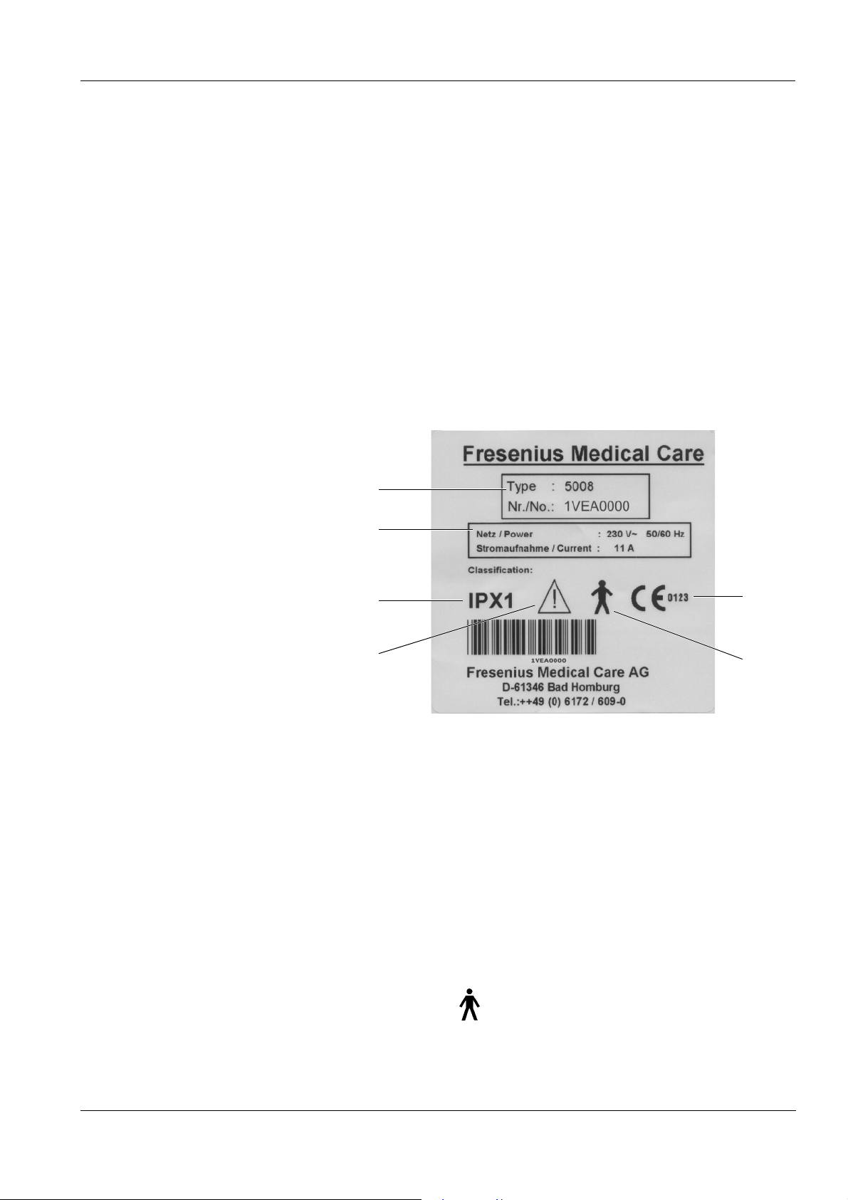
O Type label
Chapter 3: Specifications
1
2
3
4
1 Type identification, serial number
2 Power requirements
3 Protection against ingress of liquids: drip-proof
4 Caution, consult accompanying documents
5 Degree of protection against electric shock: Type B
6 CE mark
6
5
O Electrical safety (classification according to EN 60601-1, IEC 601-1)
Type of protection against
Safety class I
electric shock
Degree of protection
Type B, symbol:
against electric shock
Fresenius Medical Care 5008 SM 1/08.04 3-1
Page 12

Chapter 3: Specifications
Applicable only to the BPM
blood pressure cuff:
Degree of protection
against electric shock
Degree of protection
against ingress of liquids
Leakage currents According to EN 60601-1
EMC specifications
according to EN 60601-1-2
(IEC 601-1-2)
O Electric supply
Line voltage 100 to 230 V AC, ±10 %, 47 to 63 Hz
Type CF, symbol:
Drip-proof, symbol: IPX1
RFI emissions:
Limit class A according to EN 55011, Group 1
Immunity:
– Electrostatic discharge, atmospheric discharge: 8 kV
– Electromagnetic fields: 27 MHz – 1000 MHz: 3 V/m
– Bursts: Power line (alternating current): 1 kV
– Surge voltages (alternating current): 2 kV
(The decisive criterion is the line voltage and the operating current
specified on the type label of the system)
Connection to power
supply
Operating current
dialysis
Power supply
(internal)
Battery Lead-acid battery (maintenance-free)
O Fuses
Main power switch 2 x G 16 A (miniature circuit-breaker) rear of power supply unit
O Operating conditions
Water inlet pressure 1.5 to 6.0 bar
16 A at 230 V, regulation according to VDE 0100 part 0107
Approx. 6 A, (at 230 V)
at a water inlet temperature of 17 °C
Dialysate temperature 37 °C
Dialysate flow: 500 ml/min
+24 V ± 3 %, 20 A short-circuit proof
+18 V ± 3 %, 14 A short-circuit proof
480 W total power output
24 V, 7 Ah
Water inlet temperature 5 °C to 30 °C
with "Integrated hot rinse": 85 °C to 95 °C
Water inlet rate 1.5 l/min; at an inlet pressure of 1.5 bar
3-2 Fresenius Medical Care 5008 SM 1/08.04
Page 13

Chapter 3: Specifications
Water drain 0 to 100 cm above the floor, minimum 5 cm free fall. The water drain
must be located at a lower level than the dialyzer position.
Concentrate supply 0to-100mbar; maximum suction height 1m
with Central Delivery System (option): 0.05 to 2.0 bar
Heat dissipation Dialysis:
approx. 400 Watt (at an ambient temperature of 20 °C)
Range of operating
temperature
Atmospheric pressure 700700 hPa to 1060 hPa
Relative humidity 30 % to 75 %, temporarily 95 %
Stability 5°
IV pole load capacity Maximum: 5 kg
O External connection options
15 °C to 35 °C
Maximum load capacity of one hook: 5 kg
Caution
Any additional equipment connected to the analog and digital interfaces
of the machine must comply with the applicable EN specifications (e.g.
EN 60950 for data processing equipment and EN 60601 (IEC 601) for
electro-medical equipment).
Apart from this requirement, all configurations must comply with the
system standard EN 60601-1-1 (IEC 601-1-1), or their applicability with
regard to safety has to be proven by a certificate issued by a testing
agency authorized to test the ready-for-use machine.
The connection of additional equipment to the signal input or output
component affects the system configuration and anyone connecting
additional equipment is therefore responsible for compliance with the
system standard EN 60601-1-1 (IEC 601-1-1).
Caution
The external alarm indicators do not relieve the operator of the
obligation to observe the local alarms of the system.
LAN Interface for the exchange of data.
Electrically isolated by transformer.
Port: RJ 45
RS232 Interface for the exchange of data.
Electrically isolated by optocoupler.
Port: DSUB 9-pin
Fresenius Medical Care 5008 SM 1/08.04 3-3
Page 14

Chapter 3: Specifications
Service/diagnostics (Protected by cover!)
24 V (Protected by cover!)
Alarm output For the connection of an external alarm indicator (nurse call). (Potential-
O Override conditions
Audible alarm suppression Mute alarm time: maximum 2 minutes
For inhouse computer diagnostics.
Port: DSUB 15-pin
24 V connection (2 A fuse)
Port: Flanged socket, 4-pin
free alarm output. Alternating contact maximum 24 V/24 W).
Port: 5-pin diode plug via a shielded line; shield grounded on either side.
When overriding a safety system the responsibility for the patient’s
safety rests with the operator of the machine.
(adjustable in the SETUP)
Alarm override After confirmation of the error message and start of the blood systems:
Blood leak override Override time: maximum 2 minutes
Override air-bubble
detector
O Operating programs
T1 test Automatic test for verification of the operating and safety systems.
Preparation Defined by the optical detector located below the venous bubble
Priming and rinsing the
blood lines
Arterial and venous pressure alarm for approx. 10 seconds (window
inactive)
Air detector alarm for approx. 2 seconds
Override time: after starting removal of air: approx. 4 seconds
The T1 test is mandatory,
– after power on (not following a power failure)
– after a cleaning program
catcher.
Preparation is terminated as soon as the optical detector senses
opaque fluid in the blood lines.
Minimum rinse volume 500 ml; automatic switching to rinsing, if level in
bubble catcher detected. Automatic raising of the fluid level during the
rinse phase.
Reinfusion Reinfusion volume adjustable in the SETUP.
Return to dialysis still possible.
Dialysis Bicarbonate dialysis
ISO-UF Ultrafiltration without dialysate flow (Bergström method)
3-4 Fresenius Medical Care 5008 SM 1/08.04
Page 15

Cleaning programs Rinse clear/rinse/mandatory rinse:
Time adjustable in the TECHNICIAN's SETUP,
Temperature: approx. 37 °C,
Flow: 600, 800 ml/min (adjustable in the SETUP)
Cold disinfection/degreasing, cold disinfection:
Time adjustable in the TECHNICIAN's SETUP,
Temperature: approx. 37 °C,
Flow: max. 900 ml/min
Heat disinfection:
Time adjustable in the TECHNICIAN's SETUP,
Flow: max. 900 ml/min
In all programs:
Blood pump stops, arterial and venous line occlusion clamp closed.
Progress of the program (time-counting) is interrupted in the event of a
flow alarm.
The cleaning programs can be aborted.
The chemical disinfection program is followed by a mandatory rinse.
Chapter 3: Specifications
Flush Rinsing of the water supply area
O Dialysate circuit and safety systems
Blood leak detector Threshold of response ≤ 0.5 ml blood loss per minute into the dialysate
at a hematocrit of 0.25.
(flow rate 100 ml/min to 1000 ml/min)
Transmembrane pressure Display range: –100 to 400 mmHg
Resolution: 5 mmHg
Definition:
TMP = P
TMP = Transmembrane pressure
P
bo
P
di
P
do
Offset = Flow-dependent pressure fluctuations
– (Pdi + Pdo) / 2 + Offset
bo
= Blood pressure on the outlet side of the dialyzer
= Dialysate pressure on the inlet side of the dialyzer
= Dialysate pressure on the outlet side of the dialyzer
Ultrafiltration Selectable UF rate: 0 ml/h to 4000 ml/h (in 10 ml increments)
Maximum rate internally adjustable to 1, 2, 3, or 4 l/h.
Pump volume accuracy: ±1 % (at P
> –500 mbar)
di
The UF rate/effective blood flow ratio is being monitored during the
treatment. If an incongruity occurs a warning will be displayed after
approx. 10 seconds.
Pressure holding test Event-controlled
Fresenius Medical Care 5008 SM 1/08.04 3-5
Page 16

Chapter 3: Specifications
Balancing Accuracy: ±0.1 % related to the total dialysate volume
Maximum balancing error
F=
F=
F
UF
F
bil
F
+ F
UF
Bil
Maximum balancing error
=
Ultrafiltration error
=
Balancing error
Example:
Ultrafiltration error: with 1000 ml in 1 hour: ±1 % = ±10 ml/h
Balancing error: with 30 l fluid flow in 1 hour at a dialysate flow of
500 ml/min: ±0.1 %= ± 30 ml/h
Maximum balancing error:
F=F
UF+FBil
=(±10ml/h)+(±30ml/h)=±40ml/h
Degassing Method: Negative pressure
Dialysate concentration
(conductivity)
Display range: 12.8 to 15.7 mS/cm
Resolution: 0.1 mS/cm
Accuracy: 0.1 mS/cm
Method:
Temperature-compensated electronic conductivity meter with
adjustable alarm limits.
Concentrates Entering concentration types
Adjustment range: 125 to 151 mmol/l, depending on the concentrate
used ±10 % of the base value.
Bicarbonate readjustment range: corresponds to ±8 mmol/l
bibag
®
Bicarbonate concentrate preparation from the bibag
®
Temperature range: 15 to 35 °C
Dialysate temperature Adjustment range: (prescribed temperature) 34.0 °C to 39.0 °C
Resolution: 0.5 °C
Measuring accuracy: ±0.2 °C
Dialysate flow Display range: 100 to 1000 ml/min
Resolution: 100 ml/min
Desired values: 100 to 1000 ml/min
Measurement by means of time pulse monitoring and balancing
chamber volume
Auto flow: dialysate flow controlled in relation to the blood flow,
determined by the dialyzer.
EcoFlow: dialysate flow automatically reduced to 100 ml/min in
Preparation
Rinse and chemical
disinfection temperature
Desired temperature: 37 °C
Resolution: 0.5 °C
Measuring accuracy: ±0.2 °C
Rinse and chemical
Desired value: 600 ml/min
disinfection flow
3-6 Fresenius Medical Care 5008 SM 1/08.04
Page 17

Chapter 3: Specifications
Hot rinse and heat
disinfection temperature
Desired temperature: 85 °C
Resolution: 0.5 °C
Measuring accuracy: ±2.0 °C
Hot rinse and heat
Desired value: 600 ml/min
disinfection flow
Concentration of
disinfectant
Dilution: Disinfectant is diluted with purified water in the dialysis system
at a ratio of 1+24.
Flow alarm Dependent on the programmed flow
O Extracorporeal blood circuit and safety systems
Arterial pressure
measurement
Display range: –300 to +300 mmHg
Resolution: 5 mmHg
Accuracy: 7 mmHg (typical)
OD senses non-opaque presence:
Alarm window width: –300 to +300 mmHg
OD senses opaque presence:
Alarm window width: +40 to +200 mmHg
Default value adjustable in the SETUP, factory setting 120 mmHg
Blood pump Delivery rate: 30 to 600 ml/min
Resolution: 10 ml/min (with a line diameter of 8 mm)
Accuracy: < 5 % (without lines)
Line diameter: 4.4 mm, 6.4 mm, 8.0 mm
Blood pump stop alarm: 60 seconds
Spring-loaded rollers, fully occluding, pressure-limited to 2 bar with 8 x
2.1 pump line segment (when using the prescribed tubing systems).
(The blood pump design allows manual operation, hand crank in the
rotor, in clockwise direction only.)
Venous pressure
measurement
Display range: –100 to +500 mmHg
Resolution: 5 mmHg
Accuracy: 7 mmHg (typical)
OD senses non-opaque presence:
Alarm window width: –100 to +500 mmHg
OD senses opaque presence:
Alarm window width: 40 to 200 mmHg
Default value adjustable in the SETUP,
Factory setting 120 mmHg
adjustable over a range of 20 to 500 mmHg
(adjustable from -100 to 500 mmHg via SETUP.)
Fill level detector Method:
Capacitive measurement
Switching point 13 mm, ±4 mm from upper edge
Optical detector Method:
Infrared transmission
Fresenius Medical Care 5008 SM 1/08.04 3-7
Page 18

Chapter 3: Specifications
Air bubble detector Method:
Distinguishes between
OD light (saline or air in the tubing system)
OD dark (blood in the tubing system).
Ultrasonic transmission measurement on the line
Sensitivity:
– Air bubbles:
Bubble volume ≥ 20 µl
– Blood foam (air-blood mixture)
Air alarm:
– BP rate < 100 ml/min:
Air bubble: Volume ≥ 20 µl
Blood foam
– BP rate ≥ 100 ml/min:
10 air bubbles with an air bubble volume of < 50 µl each
or 1 air bubble with an air bubble volume of ≥ 50 µl,
Blood foam
Heparin pump Delivery rate: 0.5 to 10 ml/h
Audible alarm Setting range of the loudness of the audible alarm:
O DIASAFE
®
plus (option)
The specified data refer to the most unfavorable case with a BP rate of
0 to 600 ml/min when using the blood lines specified in chapter
Consumables.
Resolution: 0.1 ml/h
Accuracy: ±5 % for delivery rates of 0.5 to 10 ml/h and a measuring time
of 2 hours up to 1.2 bar counter-pressure
(calibrated for 30 ml Fresenius heparin syringes)
With delivery rates of <1.0 ml/h the tolerance may exceed the specified
±5 %.
Stop time: 0 minutes up to 2 hours.
Resolution: 1 minute
Bolus injection: 1.0 up to 20.0 ml
Resolution: 0.1 ml
30 ml Fresenius heparin syringe
Factory setting ≥ 65 db (adjustable)
Minimum setting: ≥ 65 db
Filter life: maximum 12 weeks.
Monitored by the dialysis system and a warning (Filter change) is
displayed.
3-8 Fresenius Medical Care 5008 SM 1/08.04
Page 19

O OCM (option)
O ONLINEplus™ (option)
Chapter 3: Specifications
When using ONLINEplus™ (option):
Filter life: maximum 100 treatments.
Monitored by the dialysis system and a warning (Filter change) is
displayed. If the warning is ignored, ONLINEplus™ will be disabled after
the respective number has been exceeded.
After 90 treatments the number of the remaining treatments will be
displayed in the cleaning programs.
Measuring accuracy of the clearance: ± 6 % standard deviation
Shortest measuring interval: 25 min
Time scale of the display: 10 s
Delivery rate: 25 to 600 ml/min (inside line diameter: 8.0 mm)
Resolution: 1 ml/min
O Single Needle (option)
Blood pump
stop alarm
Single Needle pump
Exchange volume: substituate goal 500 l adjustable in relation to
treatment parameters
Accuracy: < 5 % (without lines)
(This specification only applies to the range from 30 to 350 ml/min. With
delivery rates of < 30 ml/min the deviation may be greater.)
Volume counter display: 0.1 to 210 liters
Resolution: 0.1 liter
Spring-loaded rollers, fully occluding, pressure-limited to < 1.3 bar.
(The blood pump design allows manual operation, hand crank in the
rotor, in clockwise direction only.)
Auto sub: The sub rate is determined as a function of:
–UF rate
– Blood flow
– Hematocrit (HCT)
– Total protein (TP)
– Filter performance
During Single Needle operation 180 seconds.
Stroke volume 10 to 50 ml in increments of 5 ml
External compliance
50 ml or 60 ml stroke volume
chamber
Fresenius Medical Care 5008 SM 1/08.04 3-9
Page 20

Chapter 3: Specifications
Auto SN
Delivery rate of the
Single Needle pump
O BPM (option)
Blood pressure Display Area
Pulse Display range: 20 to 245 1/min
O BTM (option)
Required blood flow for
accurate BTM function
+20 % (programmable in the Operator setup.)
– Systole: 30 mmHg to 280 mmHg
– Diastole: 10 mmHg to 240 mmHg
– MAP: 20 mmHg to 255 mmHg
Resolution: 1 mmHg
Accuracy of measured value ±3 mmHg
Resolution: 1/min
≥120 ml/min
(The measuring and control functions of the BTM are deactivated if the
blood flow is < 100 ml/min.)
Temperature
measurement
Accuracy of the fistula temperatures (if correct ambient temperature is
indicated): ± 0.5 °C
Error in fistula temperatures per °C error of the set ambient temperature
0.08 °C (at a blood flow of 100 ml/min)
0.03 °C (at a blood flow of 300 ml/min)
Body temperature change accuracy: ± 0.2 °C
Recirculation
measurement
Accuracy of recirculation measurement
(for 2.5 °C venous bolus amplitude): ± 2 %
Maximum bolus amplitude: – 3 °C or + 3 °C
Maximum duration of the bolus: up to 10 min
Maximum dialysate temperature range used by the BTM:
33.5 °C to 39.5 °C
Body temperature control Allowed range of desired values for body temperature change rate:
– 0.5 °C/h to + 0.5 °C/h
Maximum dialysate temperature range used by the BTM:
33.5 °C to 39.5 °C
3-10 Fresenius Medical Care 5008 SM 1/08.04
Page 21

O Network (option)
Chapter 3: Specifications
Caution
The responsible organization of the network is responsible for
protecting the machine from excessive network load (e.g. by
accumulation of broadcast messages or port scans). If necessary, the
connection to the network must be established via a router or a firewall,
for example.
The system configurator is responsible for the further secure data
processing, e.g. in PC software applications.
The responsible organization of the network is responsible for the
protection of the not encrypted, transferred data.
The data transfer of alarm states via the network must not be used as
an external alarm alert (nurse call).
Fresenius Medical Care 5008 SM 1/08.04 3-11
Page 22

Chapter 3: Specifications
3-12 Fresenius Medical Care 5008 SM 1/08.04
Page 23

4Installation
4.1 Preface
Instructions for all technicians who are authorized to commission
our hemodialysis systems.
We, as manufacturers, permanently aim at delivering systems of
highest quality.
To reach this aim, we need your support.
Please commission our hemodialysis systems by uniformly using the
enclosed "initial start-up report" and enter the values determined in the
columns provided.
The following is applicable:
Corrections are necessary only if the measured values are outside
of the tolerances specified!
Chapter 4: Installation
We will then evaluate the initial start-up reports, which will enable us to
monitor the quality of our systems on their delivery.
After initial start-up, please asap send – by mail or by fax – the
completed form (Initial Start-Up Report) back to the following address:
Fresenius Medical Care
Deutschland GmbH
Werk Schweinfurt
Herrn Alfred Laus, Abt. BM
Hafenstraße 9
97424 Schweinfurt
Fax: 09721/ 678450
Thank you very much for your help!
4.2 Important Information on Initial Start-Up
This technical document is intended for initial start-up only. It is not
intended for restarting hemodialysis systems that have been shut down
or have been put out of service temporarily.
The initial start-up must be performed by the Technical Service of
Fresenius Medical Care or a person authorized by them!
Any information on initial start-up and the specifications in the Operating
Instructions must be observed.
When bringing the hemodialysis system from a cooler to a warmer
room, allow approx. 2 hours for the system to adjust to the ambient
temperature before turning the unit on.
Fresenius Medical Care 5008 SM 1/08.04 4-1
Page 24
Chapter 4: Installation
4.3 Initial Start-Up Report
5008 Initial Start-Up Report
Fresenius
Technician's name: Service report number:
Customer/Customer no.:
Inventory no.: Device no. Operating hours:
Device type including option(s):
Med ical
Care
4-2 Fresenius Medical Care 5008 SM 1/08.04
Page 25
Chapter 4: Installation
No. Description Measure-
ment
value
1 Preparation
1.1 Hemodialysis system without visible shipping damage. T
1.2 Remove the transport protection for the monitor support arm. T
Install the IV pole. T
1.3 Connect the water supply tubing. T
Connect the drain and the flush tubings. T
Protect the tubings from slipping out. T
Standard: Length 3 m, internal diameter 6 mm
T
Tubing dimensions, adjusted: Length _____ m, internal diameter_____ mm
1.4 Connect the CDS tubings and protect them from slipping out.
Apply a shrink tube marking for the CDS tubings. T
CDS 1 T
CDS 2 T
BIC T
1.5 Remove the shipping plugs from the overflows. T
1.6 When turning the hemodialysis system on, perform an audible check of the watchdog alarm. T
1.7 Rinse out the anti-freeze. T
1.8 Select the Filter change program.
Connect the filter. DIASAFE
®
plus/ONLINEplus™
T
In the service mode, delete mandatory disinfection.
Then completely run the rinse program.
2 SETUP settings (Technician's SETUP/Operator SETUP)
2.1 Check the SETUP on the hemodialysis system. T
3 Check – water inlet flow / adjustment – degassing
3.1 Check MaxWaterFlow.
Desired value: 1300 ml/min to 1550 ml/min
________ Corr.:
T Yes
T No
3.2 Perform the degassing adjustment. T
4 Check – dialysate flow
4.1 Check flow at 800 ml/min.
________ T
Desired value: 770 ml/min to 830 ml/min
Fresenius Medical Care 5008 SM 1/08.04 4-3
Page 26

Chapter 4: Installation
No. Description Measure-
ment
value
5 Check – temperature
5.1 Check PT07 (temperature) at 37 °C. (flow 500 ml/min)
Desired value: 36.8 °C to 37.2 °C (display on hemodialysis system)
Measure the reference temperature with an external measuring instrument.
Difference = Reference temperature minus PT07
Desired value – difference: –0.5 °C to +0.2 °C
6 Check – conductivity
6.1 Check CD7 (conductivity).
Desired value: approx. 13.5 mS/cm to approx. 14.5 mS/cm
Measure the reference conductivity with an external measuring instrument.
Difference = Reference conductivity minus CD7
Desired value – difference: ±0.2 mS/cm
7 Check – blood leak detector
7.1 Check the blood leak:
Desired value: 4.8 V to 5.2 V
7.2 Check the dimness:
Desired value: 4.8 V to 5.2 V
________ Corr.:
________
________ Corr.:
________
________ Corr.:
________
T Yes
T No
T Yes
T No
T Yes
T No
4-4 Fresenius Medical Care 5008 SM 1/08.04
Page 27

Chapter 4: Installation
No. Description Measure-
ment
value
8 Check – dialysate pressure
8.1 Zero point S03/S07 Corr.:
Reference measuring instrument: 0 mbar ________
Check S03.
Desired value: +16 mbar to +76 mbar
Check S07.
Desired value: +16 mbar to +76 mbar
8.2 Slope S03/S07 (+)
Reference measuring instrument: +533 mbar (± 26 mbar) ________
Check S03.
Desired value: S03 = Display of reference measuring instrument + (+16 mbar
to +76 mbar)
Check S07.
Desired value: S07 = Display of reference measuring instrument + (+16 mbar
to +76 mbar)
________
________
________
________
T Yes
T No
8.3 Slope S03/S07 (–)
Reference measuring instrument: –533 mbar (± 26 mbar) ________
Check S03.
Desired value: S03 = Display of reference measuring instrument + (+16 mbar
to +76 mbar)
Check S07.
Desired value: S07 = Display of reference measuring instrument + (+16 mbar
to +76 mbar)
________
________
Fresenius Medical Care 5008 SM 1/08.04 4-5
Page 28

Chapter 4: Installation
No. Description Measure-
ment
value
9 Check – electrical safety
In Germany according to DIN VDE 0751-1, edition 10/2001.
In other countries, observe the local regulations!
9.1 Visual inspection performed. T
9.2 Protective earth resistance maximum 0.3 ohms (with power cord) ______ Ω T
9.3 Leakage current measurement (device leakage current)
T Differential current measurement according to figure C.6
or
T Direct measurement according to figure C.5
Nominal voltage of power supply: __________ V
Device leakage current mains polarity 1 __________ µA
with line voltage __________ V
scaled to nominal voltage (maximum 500 µA, see Additional requirements) _____ µA
Device leakage current mains polarity 2 __________ µA
with line voltage __________ V
T
scaled to nominal voltage (maximum 500 µA, see Additional requirements) _____ µA
Test equipment used: ________________________
10 Check – zero point arterial/venous pressure display and venous clamp
10.1 Zero point arterial pressure display Corr.:
Check the arterial pressure display (standby operation).
Desired value: –5 mmHg to +5 mmHg
10.2 Zero point venous pressure display Corr.:
Check the venous pressure display (standby operation).
Desired value: –5 mmHg to +5 mmHg
10.3 Check – venous clamp:
A pressure change within 3 minutes must not exceed the following values:
Arterial pressure display
Maximum pressure change: ±5mmHg
Reference measuring instrument for pressure display
Maximum pressure drop: –0.1 bar
________
________
T Yes
T No
T Yes
T No
T
4-6 Fresenius Medical Care 5008 SM 1/08.04
Page 29

Chapter 4: Installation
No. Description Measure-
ment
value
11 Final check
11.1 Check the error memory. T
11.2 Save calibration data and SETUP settings on a data disk. T
11.3 Perform the T1 test. T
11.4 Run the disinfection program
(with Puristeril 340 or Puristeril plus or Diasteril or Citrosteril).
11.5 Check the alarm function during the disinfection program.
Open the shunt interlock.
Audible alarm and traffic light
11.6 Check absence of disinfectant by means of test strips (not with Citrosteril). T
11.7 Record entries in the medical device register and on the machine card. T
11.8 Operating Instructions and accessories package complete and appropriate for the system. T
T
T
Fresenius Medical Care 5008 SM 1/08.04 4-7
Page 30

Chapter 4: Installation
Date: Signature: Stamp:
The system has been released for the intended use. T Yes T No
Test equipment used:
Temperature, conductivity, pressure
(type, serial number):
Protective earth resistance, leakage current
(type, serial number):
Comments:
________________________
________________________
________________________
________________________
Date: Signature: Stamp:
4-8 Fresenius Medical Care 5008 SM 1/08.04
Page 31

4.4 Explanations on the Initial Start-Up Report
No. Description
1 Preparation
1.1 Hemodialysis system without visible shipping damage.
1.2 Remove the transport protection for the monitor support arm.
Unscrew and remove the screw.
(Keep the screw for subsequent
transportation.)
Chapter 4: Installation
Install the IV pole.
Insert the IV pole into the monitor support arm. Secure the IV pole with a threaded pin.
Place the protective cover for the monitor support arm.
Screw the IV pole hanger onto the IV pole.
1.3 Connect the water supply tubing.
Connect the drain and the flush tubings.
Protect the tubings from slipping out.
(Standard: Length 3 m, internal diameter 6 mm)
When using other tubing dimensions,
adjust the tubing parameters in the technician's-SETUP.
Tubing dimensions, adjusted: Length _____ m, internal diameter_____ mm
1.4 Connect the CDS tubings and protect them from slipping out.
Apply a shrink tube marking for the CDS tubings.
CDS 1
CDS 2
BIC
Fresenius Medical Care 5008 SM 1/08.04 4-9
Page 32

Chapter 4: Installation
No. Description
1.5 Remove the shipping plugs from the overflows.
1. Vent (water inlet chamber)
2. Vent (mixing chamber)
1
2
1.6 When turning the hemodialysis system on, perform an audible check of the watchdog alarm.
1.7 Rinse out the anti-freeze.
1.8 Select the Filter change program.
Connect the filter. DIASAFE
®
plus/ONLINEplus™
In the service mode, delete mandatory disinfection.
Then completely run the rinse program.
2 SETUP settings (Technician's SETUP/Operator SETUP)
2.1 Check the SETUP on the hemodialysis system.
Make the appropriate settings for the respective hospital, if necessary.
3 Check – water inlet flow / adjustment – degassing
3.1 In the service mode, select FLOW DIAGRAM.
Basic requirements:
The hemodialysis system must be closed.
Flow on.
Check MaxWaterFlow.
Desired value: 1300 ml/min to 1550 ml/min
Use A04 for making corrections, if necessary.
(If it is not possible to set a water inlet flow ≥ 1300ml/min, it will not always be possible to achieve the
dialysate flow of 1000ml/min.)
3.2 In the service mode, select CALIBRATE.
Basic requirements:
Flow on.
Perform the degassing adjustment.
Touch the Degassing (A01/P01) button.
4-10 Fresenius Medical Care 5008 SM 1/08.04
Page 33

No. Description
4 Check – dialysate flow
4.1 In the service mode, select CALIBRATE.
Basic requirements:
The hemodialysis system must be closed.
Flow on, flow 800 ml/min
Check flow.
Desired value: 770 ml/min to 830 ml/min
5 Check – temperature
5.1 In the service mode, select CALIBRATE.
Basic requirements:
The hemodialysis system must be closed.
Temperature 37 °C, flow on, flow 500 ml/min,
Response time approx. 10 min.
Check PT07 (temperature).
Desired value: 36.8 °C to 37.2 °C (display on hemodialysis system)
Chapter 4: Installation
Measure the reference temperature with an external measuring instrument.
Difference = Reference temperature minus PT07
Desired value – difference: –0.5 °C to +0.2 °C
Example:
PT07: 37 °C
Desired value reference temperature: 36.5 °C to 37.2 °C
6 Check – conductivity
6.1 In the service mode, select CALIBRATE.
Basic requirements:
The hemodialysis system must be closed.
External measuring instrument (e.g. UMED) connected for at least 5 minutes.
Temperature 37 °C, flow on
Check CD7 (conductivity).
Desired value: approx. 13.5 mS/cm to approx. 14.5 mS/cm
Measure the reference conductivity with an external measuring instrument.
Difference = Reference conductivity minus CD7
Desired value – difference: ±0.2 mS/cm
7 Check – blood leak detector
In the service mode, select CALIBRATE.
Basic requirements:
The hemodialysis system must be closed. (Avoid external light.)
Temperature of approx. 37 °C achieved, flow on, flow 500 ml/min,
7.1 Check the blood leak:
Desired value: 4.8 V to 5.2 V
7.3 Check the dimness:
Desired value: 4.8 V to 5.2 V
Fresenius Medical Care 5008 SM 1/08.04 4-11
Page 34

Chapter 4: Installation
No. Description
8 Check – dialysate pressure
In the service mode, select CALIBRATE.
Basic requirements:
The hemodialysis system must be closed.
The reference measuring instrument must be placed at the bottommost position of the IV pole.
Dialyzer couplings must be connected to the reference instrument.
Flow on until dialysate lines and reference measuring instrument are free from air. Then flow off.
8.1 Zero point S03/S07
Reference measuring instrument: 0 bar
Open the vent valve (UMED).
Using a syringe (filled with fluid) set a value of 0 bar, via the vent valve.
Check S03.
Desired value: +16 mbar to +76 mbar
Check S07.
Desired value: +16 mbar to +76 mbar
8.2 Slope S03/S07 (+)
Reference measuring instrument: +533 mbar (± 26 mbar)
Using a syringe (filled with fluid) set a value of +533 bar, via the vent valve.
Check S03.
Desired value: S03 = Display of reference measuring instrument + (+16 mbar to +76 mbar)
Check S07.
Desired value: S07 = Display of reference measuring instrument + (+16 mbar to +76 mbar)
8.3 Slope S03/S07 (–)
Reference measuring instrument: –533 mbar (± 26 mbar)
Using a syringe (filled with fluid) set a value of –533 bar, via the vent valve.
Check S03.
Desired value: S03 = Display of reference measuring instrument + (+16 mbar to +76 mbar)
Check S07.
Desired value: S07 = Display of reference measuring instrument + (+16 mbar to +76 mbar)
4-12 Fresenius Medical Care 5008 SM 1/08.04
Page 35

No. Description
9 Check – electrical safety
In Germany according to DIN VDE 0751-1, edition 10/2001.
In other countries, observe the local regulations!
9.1 Visual inspection performed.
– Fuses accessible from the outside comply with the indicated values.
– Labels and labelings are present and legible.
– The mechanical condition permits further safe use.
– There are no signs of damage or dirt.
– No signs of damage on the power cord.
9.2 Protective earth resistance maximum 0.3 ohms (with power cord)
The protective earth resistance must be checked on the following four measurement points.
1. Measurement point: power supply unit
(power supply unit housing)
Chapter 4: Installation
2. Measurement point: shunt door
Fresenius Medical Care 5008 SM 1/08.04 4-13
Page 36

Chapter 4: Installation
No. Description
3. Measurement point: potential
equalization
4. Measurement point: heater rod chamber
4-14 Fresenius Medical Care 5008 SM 1/08.04
Page 37

No. Description
9.3 Leakage current measurement (device leakage current)
M1
Chapter 4: Installation
Differential current measurement
according to figure C.6
L
N
PE
or
L
N
PE
L(N)
N(L)
Direct measurement according to figure
C.5
MD
Fresenius Medical Care 5008 SM 1/08.04 4-15
Page 38

Chapter 4: Installation
No. Description
Basic requirements:
– Measurement of the protective earth resistance performed.
– Perform the measurement with the hemodialysis system being at operating temperature.
– Dialysate:
Dialysis temperature: ≥ 37 °C
Dialysate flow: ≥ 300 ml/min
Conductivity: ≥ 13 mS/cm
– When performing a direct measurement, the following precautions also must be observed:
The system must be insulated when installed.
All external connections must have been removed from the system.
The line voltage during the measurement will be recorded, as well as the maximum device leakage
current of both mains polarities, scaled to the nominal voltage of the power supply. Maximum device
leakage current: 500 µA
Example:
Line voltage during the measurement: 225 V
Device leakage current
for mains polarity 1: 180 µA
for mains polarity 2: 120 µA
Maximum value of both mains polarities: 180 µA
Nominal voltage of power supply: 230 V
Scaled to nominal voltage: 184 µA
(180 µA: 225 V x 230 V = 184 µA
Device leakage current < 500 µA: OK
Additional requirements:
If the device leakage current, scaled to the nominal voltage, is higher than 90 % of the admissible alarm
limit (450 µA), the last measured value or the first measured value must additionally be considered for
the rating.
If the device leakage current has considerably increased since the last measurement or has continuously
increased since the first measurement (creeping deterioration of the insulation), or if the sum composed
of the current value plus the difference since the last measurement is >500 µA, the measurement has
not been completed successfully.
Example 1:
Device leakage current: 470 µA
Last measured value: 450 µA
470 + (470 – 450) = 470 + 20 = 490; is OK
Example 2:
Device leakage current: 470 µA
Last measured value: 390 µA
470 + (470 – 390) = 470 + 80 = 550; not passed
10 Check – zero point arterial/venous pressure display and venous clamp
10.1 Zero point arterial pressure display
Basic requirements:
Blood lines inserted, pressure domes coupled, standby operation.
Check the arterial pressure display.
Desired value: –5 mmHg to +5 mmHg
4-16 Fresenius Medical Care 5008 SM 1/08.04
Page 39

No. Description
10.2 Zero point venous pressure display
Basic requirements:
Blood lines inserted, pressure domes coupled, standby operation.
Check the venous pressure display.
Desired value: –5 mmHg to +5 mmHg
10.3 Check – venous clamp
Basic requirements:
– Blood lines inserted, standby operation.
– Connect the arterial and the venous branch using the adapter fitting included.
– Remove the line from the arterial clamp.
– Clamp the blood line before the blood pump and on the venous drip chamber.
– Connect the external pressure measuring instrument to the venous bubble catcher.
– Connect the syringe and the one-way valve (if present) to the venous bubble catcher.
Chapter 4: Installation
Pressure build-up – arterial side:
Open the venous clamp.
Using a syringe, build up an arterial
pressure of 50 mmHg to 100 mmHg.
Observe the arterial display on the
hemodialysis system.
Close the venous clamp.
Pressure build-up – venous side:
Venous clamp closed.
Using a syringe, build up a pressure of
2.5 bar to 2.7 bar.
Observe the display on the external
reference measuring instrument.
Maximum pressure change within 3 minutes on the arterial pressure display of the hemodialysis system
±5 mmHg.
Maximum pressure drop within 3 minutes on the display of the reference measuring instrument –0.1 bar.
Fresenius Medical Care 5008 SM 1/08.04 4-17
Page 40

Chapter 4: Installation
No. Description
11 Final check
11.1 Check the error memory.
With service program:
Erase error memory and service data recorder.
11.2 With service program:
Save calibration data and SETUP settings on a data disk.
11.3 Perform the T1 test.
11.4 Run the disinfection program:
(with Puristeril 340 or Puristeril plus or Diasteril or Citrosteril)
11.5 Check the alarm function during the disinfection program.
Open the shunt interlock.
Audible alarm and traffic light
Alarm message
Close the shunt interlock.
The disinfection program will be continued.
11.6 Check absence of disinfectant by means of test strips (not with Citrosteril).
11.7 Record entries in the medical device register and on the machine card.
11.8 Operating Instructions and accessories package complete and appropriate for the system.
4-18 Fresenius Medical Care 5008 SM 1/08.04
Page 41

5Setup
5.1 Operator Setup
Chapter 5: Setup
Touch the SYSTEM menu button.
Insert the operator card.
Touch the OPERATOR SETUP button on the SYSTEM SCREEN.
Select the desired function from the Operator setup SCREEN.
Make changes, if required, and save.
How to use the Operator setup:
– Save with OK.
– Select default values with Logo.
O Tubing system
Submenu Default value Value range Resolution Selectable
options
Tubing system AV Set 5008 – – –
O Blood pump
Submenu Default value Value range Resolution Selectable
options
Pump segment 8.0 mm – – (4.4 mm)
(6.4 mm)
8.0 mm
Delivery rates
Prime 100 ml/min 30–600 ml/min 10 ml/min –
Precirculation 100 ml/min 30–600 ml/min 10 ml/min –
Reinfusion 100 ml/min 30–300 ml/min 10 ml/min –
Fresenius Medical Care 5008 SM 1/08.04 5-1
Page 42

Chapter 5: Setup
O Rinse/reinfusion volume
Submenu Default value Value range Resolution Selectable
options
Preparation (NaCl)
Rinse vol. 500 ml 500–5000 ml 100 ml –
(UF rinse vol.) (0 ml) (0–5000 ml) (100 ml) (–)
Reinfusion (NaCl)
Reinfusion volume 250 ml 0–480 ml 10 ml –
O Anticoagulation
Submenu Default value Value range Resolution Selectable
options
Heparin
Heparinization Yes – – Yes
No
Heparin unit ml – – ml
I.U.
Heparin start Automatic – – Automatic
Manual
Hep. rate 1.2 ml/h 0.5–10.0 ml/h 0.1 ml/h –
10 I.U./h 10–25 000 I.U./h 10 I.U./h –
Stop time 0:30 0:00–2:00 0:01 –
Syringe Fresenius 30 ml – – Depending on
Technician's
Setup
(define syringe
types)
Bolus 5.0 ml/h 1.0–20.0 ml/h 0.1 ml/h –
1000 I.U./h 0–15 000 I.U./h 10 I.U./h –
5-2 Fresenius Medical Care 5008 SM 1/08.04
Page 43

Chapter 5: Setup
O Dialysate
Submenu Default value Value range Resolution Selectable
options
Dialyzer FX series – – FX series
F series
others
Auto flow factor 1.2 (depending on
– – not adjustable
dialyzer)
Empty bibag Automatic – – Automatic
Manual
O Ultrafiltration
Submenu Default value Value range Resolution Selectable
options
Maximum UF rate 3000 ml/h 500–4000 ml/h 10 ml/h –
Maximum profile rate 3500 ml/h 3010–4000 ml/h 10 ml/h –
Program. UF profile Closed – – Closed
Released
UF start Automatic – – Automatic
Manual
UF goal 0 ml 0–9990 ml 10 ml –
UF time 0hrs0min 0–24hrs. 1min –
UF rate 0 ml/min 0–4000 ml/min 10 ml/min –
Fresenius Medical Care 5008 SM 1/08.04 5-3
Page 44

Chapter 5: Setup
O Alarm processing
Submenu Default value Value range Resolution Selectable
options
Tone Mute time 120 seconds 60–120 seconds 10 seconds –
Warning times
Flow off 10 min – – 10 min
20 min
30 min
UF off 5 min 5–15 min 1 min –
Heparin off 1 min 1–5 min 1 min –
Arterial/venous
pressure settings
Art. alarm limit Centered – – Centered
Asymmetric
Art. window width 100 mmHg 40–200 mmHg 10 mmHg –
Ven. alarm limit Asymmetric – – Asymmetric
Centered
Ven. window width 100 mmHg 40–200 mmHg 10 mmHg –
Ven. window position Unlimited – – Unlimited
≥ 20 mmHg
5-4 Fresenius Medical Care 5008 SM 1/08.04
Page 45

Chapter 5: Setup
O User interface
Submenu Default value Value range Resolution Selectable
options
Screen saver
Screen saver Yes – – Yes
No
Delay 5 min 1–60 min 1 min –
Graphics The diagram types listed under selectable options can be assigned to a group.
Each group can contain a maximum of 4 graphics. Each diagram type can be
contained in any group, but only once. Graphics can be assigned only if the
particular option is available.
Group 1 UF Na diagram
OCM diagram
Pressure graphs
BPM history
– – UF Na diagram
Pressure graphs
BTM
BPM
BPM (MAP)
BVM
OCM diagram
BPM history
Group 2 BPM
– – See group 1
BPM (MAP)
Group 3 – – See group 1
Group 4 – – See group 1
Defining options A maximum of 4 option buttons may be added The option buttons which have been
added will appear on the lower right above the SYSTEM button.
(If the BPM option is available, a maximum of 3 options may be created.)
Options can be added only if the particular option is available.
Option HEPARIN
ONLINE
– – HEPARIN
EMERGENCY
CIRCULATE
SINGLE NEEDLE
ONLINE
OCM
BPM
BVM
BTM
Defining controls
– ––––
Fresenius Medical Care 5008 SM 1/08.04 5-5
Page 46

Chapter 5: Setup
O Cleaning
Submenu Default value Value range Resolution Selectable
options
Mand. cleaning pgm.
after treatment
Yes––Yes
No
5-6 Fresenius Medical Care 5008 SM 1/08.04
Page 47

Chapter 5: Setup
O Auto On
Submenu Default value Value range Resolution Selectable
options
Weekly programs The program and the power-up time may be preselected.
Then turn programming on or off via Status.
If various programming actions have been performed, it is possible to turn them all
on or off via the Auto On Programs I/O button.
Program No program – – Rinse
Heat disinfection
T1 Test
No program
Power-up time 00:00 00:00–24:00 1 min –
Single programs The program and the power-up time may be preselected.
Then turn programming on or off via Status.
If various programming actions have been performed, it is possible to turn them all
on or off via the Auto On Programs I/O button.
Program No program – – Rinse
Heat disinfection
T1 Test
No program
Power-up time 00:00 00:00–24:00 1 min –
The bibag® may be installed after completion of the last
disinfection of the 5008 hemodialysis system (72 hours
maximum before the treatment).
For profiting from this possibility, observe the following notes.
Requirements:
– Pre-program the T1 test under Auto On.
(Observe the time programming of the osmosis installation.)
– CDS for acid connected.
Caution
After removal of the foil, immediately connect the bibag
techniques. Then close the bicarbonate flap.
®
using aseptic
Fresenius Medical Care 5008 SM 1/08.04 5-7
Page 48

Chapter 5: Setup
O Emergency (response after touching the Emergency button)
Submenu Default value Value range Resolution Selectable
options
UF off Yes – – Yes
No
Blood flow reduction Yes – – Yes
No
Blood pressure
measurement
No––Yes
No
Online bolus Yes – – Yes
No
Bolus 90ml 90–240ml 30ml –
Bolus rate 200 ml/min 50–250ml/min 10ml/min –
O Patient card
Submenu Default value Value range Resolution Selectable
options
Patient card Writing to the patient card:
– Patient card button In the Operator setup touched.
– Remove the operator card.
– Insert the patient card.
– Message: Patient card for ... date of birth... – OK.
– Touch the OK button.
– Insert the desired patient data.
(After touching the desired field, the patient data may be entered via the
keypad.)
– Touch the OK button to confirm the entered patient data.
Visually check the confirmed patient data.
– Touch the Create patient card button.
– Message: Saving data to card. Leave card inserted!
– Remove the patient card after the message disappeared.
First name––––
Surname––––
Finesse ID––––
Date of birth––––
5-8 Fresenius Medical Care 5008 SM 1/08.04
Page 49

Chapter 5: Setup
O ONLINE (Can only be selected if the device option exists and if Filter 2 is set in the submenu
Machine options in the Technician's Setup.)
Submenu Default value Value range Resolution Selectable
options
Treatment mode
Treatment mode HDF postdilution – – HD
HDF predilution
HDF postdilution
HF predilution
HF postdilution
Bolus
Bolus 150 ml 90–240 ml 30 ml –
Bolus rate 200 ml/min 100–250 ml/min 10 ml/min –
Preparation (Online)
Onl. rinse vol. 800 ml 500–5000 ml 100 ml –
Onl. UF rinse vol. 500 ml 0–5000 ml 100 ml –
Reinfusion (online)
Reinfusion volume 360 ml 60–480 ml 60 ml –
Substitution
Auto-sub Yes – – Yes
No
O OCM (Can only be selected if the device option exists.)
Submenu Default value Value range Resolution Selectable
options
OCM start Automatic – – Automatic
Manual
Kt/V warning
(see OCM description)
Yes––Yes
No
Fresenius Medical Care 5008 SM 1/08.04 5-9
Page 50

Chapter 5: Setup
O Single Needle (Can only be selected if the device option exists.)
Submenu Default value Value range Resolution Selectable
options
Maximum stroke vol. 50 ml – – –
Stroke volume 35 ml 10-50 ml 5 ml –
Rate ratio
+20% –60% to +60% 5% –
(ratio blood pump
speed to SN pump
speed)
O Miscellaneous
Submenu Default value Value range Resolution Selectable
options
Installation place Installation place of the 5008 hemodialysis system may be entered here (e.g. name
of the clinic).
O BPM (Can only be selected if the device option exists.)
Submenu Default value Value range Resolution Selectable
options
SYS max 165 mmHg 100–280 mmHg 1 mmHg –
DIA max 100 mmHg 100–240 mmHg 1 mmHg –
MAP max 120 mmHg 80–255 mmHg 1 mmHg –
PULSE max 150 1/min 50–245 1/min 1 1/min –
SYS min 90 mmHg 30–140 mmHg 1 mmHg –
DIA min 50 mmHg 10–90 mmHg 1 mmHg –
MAP min 70 mmHg 20–120 mmHg 1 mmHg –
PULSE min 401/min 20–1401/min 11/min –
Pressure preselection 160 mmHg 100–290 mmHg 1 mmHg –
5-10 Fresenius Medical Care 5008 SM 1/08.04
Page 51

Chapter 5: Setup
O BTM (Can only be selected if the device option exists.)
Submenu Default value Value range Resolution Selectable
options
BTM
BTM
(Tubing detection after
Active––Active
Passive
turning power on)
Recirculation
Recirculation
measurement
Automatic – – Automatic
Manual
Body temperature
Temp. control Automatic – – Automatic
Manual
Temperature change 0.0 °C –0.5 to +0.5 °C/h 0.1 °C/h –
Room temperature
Room temperature 20.0 °C 15.0–35.0 °C 1.0 °C –
Fresenius Medical Care 5008 SM 1/08.04 5-11
Page 52

Chapter 5: Setup
5-12 Fresenius Medical Care 5008 SM 1/08.04
Page 53

5.2 Technician's SETUP
O Hydraulics settings
Chapter 5: Setup
Selecting the technician's SETUP
System turned power on.
Insert the technician's card.
Touch the SYSTEM button.
Touch the SERVICE button in the SYSTEM screen.
Touch the SETUP button on the SERVICE SCREEN.
How to use the OPERATOR SETUP
Save with OK.
Touch the logo to select default values.
Submenu Default value Value range Resolution Selectable
options
Machine options
Machine options DIASAFE
plus or
–––
®
ONLINEplus™
(not adjustable)
Filter1–––Filter not present
Present
Filter2–––Filter not present
Present
Water inlet tube
Length 3.0 m 1.0–5.0 m 0.1 m –
Internal diameter 6 mm 3–20 mm 1 mm –
O EBM settings
Submenu Default value Value range Resolution Selectable
options
Machine options
Motor type Premotec – – Premotec
Papst
others
Fresenius Medical Care 5008 SM 1/08.04 5-13
Page 54

Chapter 5: Setup
O Dialysate default values
Submenu Default value Value range Resolution Selectable
options
Concentrate Depending on the
setting in the
technician's
SETUP item
"Define
concentrates".
– – Depending on the
setting in the
technician's
SETUP item
"Define
concentrates".
SK-F 203
Prescr. Na 138 mmol/l 125–160 mmol/l 1 mmol/l –
Prescr. Bic 32.0 mmol/l 0–40.0 mmol/l 1 mmol/l –
Flow 500 ml/min 100–1000 ml/min 100 ml/min –
Auto flow Yes – – Yes
No
Auto flow factor 1.9 1.0–2.0 0.1 –
Temperature 36.5 °C 34 °C–39 °C 0.5 °C –
5-14 Fresenius Medical Care 5008 SM 1/08.04
Page 55

Chapter 5: Setup
O Define concentrates
Submenu Default value Value range Resolution Selectable options
Operator list AC-F 113 (10 l)
AC-F 219/3 (6 l)
AC-F 311 (6 l)
AC-F 411 (6 l)
AC-F 419 (6 l)
SK-F 203 (6 l)
SK-F 311 (10 l)
AC-F 213 (6 l)
––
SK-F 003
SK-F 016
SK-F 119
SK-F 119/4
SK-F 119/1
SK-F 119/5
SK-F 119/2
SK-F 113/1
SK-F 118
SK-F 109
SK-F 103
SK-F 112
SK-F 113
SK-F 1/513
SK-F 219/0
SK-F 219/3
SK-F 207
SK-F 219/1
SK-F 2129
SK-F 21/56
SK-F 213/4
SK-F 212/1
SK-F 216/1
SK-F 219
SK-F 21/53
SK-F 209
SK-F 218/1
SK-F 218
SK-F 202
SK-F 203
SK-F 212
SK-F 216
SK-F 213
SK-F 223
SK-F 212/2
SK-F 2/513
SK-F 318/1
SK-F 313/2
SK-F 301
SK-F 309
SK-F 311
SK-F 312/1
SK-F 316
SK-F 313/1
SK-F 318
SK-F 303
SK-F 313
SK-F 3/513
SK-F 412/1
SK-F 419
SK-F 416
SK-F 411/1
SK-F 413/1
SK-F 401
SK-F 411
SK-F 413
AC-F 113
AC-F 119
AC-F 113/1
AC-F 119/1
AC-F 203
AC-F 213
AC-F 218
AC-F 219
AC-F 223
AC-F 212/1
AC-F 213/4
AC-F 216/1
AC-F 218/1
AC-F 219/0
AC-F 219/1
AC-F 219/3
AC-F 219/4
AC-F 219/5
AC-F 303
AC-F 311
AC-F 313
AC-F 316
AC-F 318
AC-F 312/1
AC-F 313/3
AC-F 318/1
AC-F 216
AC-F 411
AC-F 413
AC-F 419
AC-F 412/1
AC-F 413/1
AC-F 016
Fresenius Medical Care 5008 SM 1/08.04 5-15
Page 56

Chapter 5: Setup
O Define syringe types
Submenu Default value Value range Resolution Selectable
options
Operator list Fresenius 30 ml – – B&D 10 ml
Fresenius 10 ml
Nipro10ml
Terumo 10 ml
Nipro20ml
B&D 20 ml
Terumo 20 ml
JMS 20 ml
B. Braun 30 ml
B&D 30 ml
Dispomed 30 ml
Fresenius 30 ml
Nipro30ml
Terumo 30 ml
O Define cleaning parameters
Submenu Default value Value range Resolution Selectable
options
PAGE 1
Cleaning pgm
combination
Heat disinfection – – Rinse
Heat disinfection
Degreasing/cold
disinfection
Disinfection port 1 Diasteril
®
(6 l) – – Diasteril
(6000 ml)
Citrosteril
(5000 ml)
Puristeril
(4400 ml)
Disinfection port 2 Sporotal
3l)
®
100 (4.
– – Sporotal®100
(4300 ml)
®
®
®
340
5-16 Fresenius Medical Care 5008 SM 1/08.04
Page 57

Chapter 5: Setup
Submenu Minimum time (minutes : seconds) Maximum time
Flow 600 ml/min Flow 800 ml/min
(minutes)
Resolution
(minutes)
PAGE 2
Rinse clear Not programmable – see Rinse clear below
Hot rinse
with/without
DIASAFE
®
plus
15:00 12:50 60 1
ONLINEplus™ 17:30 14:50 60 1
Integrated hot rinse
with/without
DIASAFE
®
plus
05:00 05:00 60 1
ONLINEplus™ 05:00 05:00 60 1
Cool down rinse
with/without
DIASAFE
®
plus
03:45 03:20 not adjustable not adjustable
ONLINEplus™ 04:30 03:55 not adjustable not adjustable
Rinse
with/without
DIASAFE
®
plus
06:50 05:50 600 1
ONLINEplus™ 07:45 06:35 600 1
Rinse clear
with/without
DIASAFE
®
plus
06:15 05:15 60 1
ONLINEplus™ 07:10 06:00 60 1
Disinfection
with/without
DIASAFE
®
plus
08:40 08:40 60 1
ONLINEplus™ 10:15 10:15 60 1
Heat disinfection
with/without
DIASAFE
®
plus
13:40 13:40 60 1
ONLINEplus™ 15:40 15:40 60 1
Mandatory rinse
with/without
DIASAFE
®
plus
16:10 13:35 60 1
ONLINEplus™ 18:10 15:05 60 1
Fresenius Medical Care 5008 SM 1/08.04 5-17
Page 58

Chapter 5: Setup
Submenu Default value Value range Resolution Selectable
options
PAGE 2
Cleaning flow 800 ml/min – – 800 ml/min
600 ml/min
Heater rod power
rating
Audible info No
2000 W
(not adjustable)
–––
–––
(not adjustable)
Auto Off 10 min – – Immediately
10 min
30 min
60 min
No
Mandatory disinfection
after treatment
Disinfection note No
No
(not adjustable)
–––
–––
(not adjustable)
O Define options (cannot be set yet)
O Define screen pages (cannot be set yet)
O Novram
Submenu Selectable options
Novram Delete mandatory disinfection
Delete mandatory rinse
5-18 Fresenius Medical Care 5008 SM 1/08.04
Page 59

Chapter 5: Setup
O Miscellaneous
Submenu Default value Value range Resolution Selectable
options
Date
(current date)
Time
(current time)
Loudness6––1–9
Sound1––0–3
Sound check Off – – Off
Audible alarm
Audible warning
Audible info
Start-up sound
Skip T1 test No – – No
Yes
RecordsYes––Yes
No
Flash Flash 1 – – Flash 1
Flash 2
Recording rate Low – – Low
High
Fresenius Medical Care 5008 SM 1/08.04 5-19
Page 60

Chapter 5: Setup
5-20 Fresenius Medical Care 5008 SM 1/08.04
Page 61

Chapter 5: Setup
5.3 Information Regarding the Setting of Concentrates in the
Technician’s Setup
The following setting limits must be observed in the technician’s menu
for the specification of the concentrates:
O Explanation of the terms used in the Settings menu
+
Na
(sodium),
+
K
(potassium),
2+
Ca
(calcium),
2+
Mg
(magnesium),
-
C
(chloride),
-
HCO3
(bicarbonate)
NaB Is the concentration of the sodium in the ready-to-use dialysate which
Is the concentration of the respective ions in the ready-to-use dialysate.
originates from the bicarbonate concentrate. If the bicarbonate
concentrate does not contain any additional saline, this value equals the
total of the values for bicarbonate and acid (acid is most cases identical
with the acetate)
If the bicarbonate concentrate contains additional saline, the value for
NaB equals the total of the final concentration of this saline in the readyto-use dialysate, the bicarbonate and the acid.
If the value set for NaB is zero it is assumed that the concentrate is pure
bicarbonate concentrate, the software will set NaB = HCO3
-
CH3COO- Acetate, is the concentrate of the acetate in the ready-to-use dialysate.
Acid CH
Glucose Is the concentration of the glucose in the ready-to-use dialysate.
O Mixing ratio
Acid proportion Proportion of the acidic concentrate of the composition, is the reference
Bic components Proportion of the bicarbonate concentrate of the composition. In case of
In case of bicarbonate dialysis:
If the value set here is zero, it is assumed that the prescription contains
hydrochloric acid (HCl).
COOH or HCl, is the concentration of the acid which originates from
3
the acidic or sodium concentrate (prior to the reaction with the
bicarbonate component), in case of bicarbonate dialysis it is in most
cases identical with the acetate. If the value set here is zero, it is
assumed that it is identical with acetate, i.e. that the acetate of the
ready-to-use dialysate is produced by the reaction of the acetic acid of
the acid concentrate with the bicarbonate and that the concentrates did
not contain any acetate prior to this reaction. This is the normal case.
Acetic acid and hydrochloric acid are considered as acid.
Caution: The unit of measure is g/L
quantity of the mixing ratio, constant = 1
acetate dialysis the value is 0.
Fresenius Medical Care 5008 SM 1/08.04 5-21
Page 62

Chapter 5: Setup
H2O components Proportion of the RO water of the composition.
O 3mix dialysis
Indi components Proportion of the individual concentrate of the composition. The value 0
stands for no individual concentrate dialysis.
NaI Is the concentration of the sodium (NaCl) in the ready-to-use dialysate
which originates from the individual concentrate.
ConcI Is the concentration of the acid in the ready-to-use dialysate which
originates from the individual concentrate. The Fresenius 3mix system
currently uses hydrochloric acid. The use of acetic acid is possible if this
is considered in the specification of the acetate proportion.
O Setting limits for acetate dialysis
Name Unit Min. value Max. value Condition
+
sodium 1 mmol/L 125 150
Na
+
K
potassium 1/100 mmol/L 0.00 5.00
2+
Ca
calcium 1/1000 mmol/L 0.00 2.500
2+
Mg
1/100 mmol/L 0.20 1.00
magnesium
-
Cl
chloride 1/100 mmol/L 80.00 126
-
HCO3
1/10 mmol/L 0 0
bicarbonate
CH
COO-
3
30.00 40.00
acetate
Glucose gm/L 0 3
Acid proportion
(here = acetate
nondimensional
1 ( = constant)
concentrate
proportion)
Bic components non-
0
dimensional
H
O
2
components
nondimensional
19 40
All others 0
5-22 Fresenius Medical Care 5008 SM 1/08.04
Page 63

O Setting limits for bicarbonate dialysis (3mix settings are not implemented)
Name Unit Min. value Max. value Condition
+
Na
sodium 1 mmol/L 125 150
Requirements: the NaCl (saline) concentration in the acidic concentrate must be ≥ 1800 mmol/l.
+
K
potassium 1/100 0.00 5.00
2+
Ca
calcium 1/1000 mmol/l 0.00 2.500
2+
Mg
1/100 mmol/l 0.20 1.00
magnesium
-
Cl
chloride 1/100 mmol/l 80.00 126
-
HCO3
1/10 mmol/l 24.0 40.0
bicarbonate
Requirements: the concentration of bicarbonate in the bicarbonate concentrate must be ≥ 6%.
Chapter 5: Setup
CH
COO-
3
1/100 mmol 0.00 10.00 Acetate and acid input ≤ 10.00
acetate
Acid 1/100 mmol 1.50 4 in most cases = acetate
Glucose gm/L 0 3
Acid proportion non-
1 ( = constant)
dimensional
Bic components non-
dimensional
Bic
components =
H
O component
2
MixBic =
H
O component
2
s x 0.055
s x 0.017
H
O
2
components
nondimensional
17 800 and
additional 19
000 bic
components
50.000 The following mixing ratio
facilitates the calculation:
Mix = 1+Bic components +H
components ≥ 20
Indi components Not implemented.
NaB 1/10 mmol/L = bicarbonate = bicarbonate +
30.0
The table with possible settings offers optimum flexibility. It is, however,
indispensable that all persons entering prescriptions are specially
trained and instructed.
The input limits cannot guarantee that the prescriptions entered will
affect several setting limits and will not generate a conductivity alarm,
are physiologic.
O
2
The allowed concentrate setting limits specified above also affect the
limits which can be set by the operator. Some of the expected operator
adjustments may then no longer be possible:
Operator setting limits:
Fresenius Medical Care 5008 SM 1/08.04 5-23
Page 64

Chapter 5: Setup
Prescribed Na Concentration of the prescription ± 10% (rounded off)
Prescribed bicarbonate Concentration of the prescription ± 8 mmol/L
and:
12.8 mS/cm ≤ expected conductivity ≤15.7 mS/cm
and:
125 mmol/L ≤ prescribed Na ≤ 155 mmol/L
and:
20 mmol/L ≤ prescribed bicarbonate ≤ 40 mmol/L
and:
12.8 mS/cm ≤ expected conductivity ≤15.7 mS/cm
Whichever condition is the most stringent applies.
5-24 Fresenius Medical Care 5008 SM 1/08.04
Page 65

6 TSC / TMC / Maintenance
6.1 Important Information
This chapter includes the Technical Safety Checks (TSC), the
Technical Measurement Checks (TMC) and the Maintenance
Procedures (MA) to be performed.
(Technical Measurement Checks are applicable only to Item 6.4 BPM.)
The Technical Safety Checks (TSC) and the Technical Measurement
Checks (TMC) must be carried out every 2 years (24 months).
Performance of the Technical Safety Checks must be entered in the
Medical Device Register.
The following applies to the technical measurement checks. After
successful completion of the technical measurement checks, the
respective parts of the hemodialysis system must be identified with a
sign (label). This label must, in a unique and traceable manner, specify
the year of the next Technical Measurement Check and the authority or
person having performed the Technical Measurement Check.
Chapter 6: TSC / TMC / Maintenance
Performance of the Maintenance Procedures (MA) is recommended by
the manufacturer. The maintenance procedures must also be carried
out every 2 years (24 months) and ensure smooth operation.
Precautions for working on the system
Assembly, extensions, adjustments, modifications or repairs may only
be carried out by the manufacturer or persons authorized by him.
The activities described in the Technical Manual require the availability
of the necessary technical measuring equipment and accessories.
Respect the following precautions when working on the open system:
Protect the components against ingress of fluids.
Do not touch live parts (e.g. connectors of the power cord or heater).
When repairing and when replacing spare parts, observe the applicable
ESD precautions (e.g. EN 100 015-1).
Fresenius Medical Care 5008 SM 1/08.04 6-1
Page 66

Chapter 6: TSC / TMC / Maintenance
6-2 Fresenius Medical Care 5008 SM 1/08.04
Page 67

Chapter 6: TSC / TMC / Maintenance
6.2 Test Report – Technical Safety Checks, Technical Measurements Checks and Maintenance Procedures
TSC / TMC / MA Test Report
5008 for the Technical Safety Checks and
Technical Measurement Checks and Maintenance
Procedures to be performed every 2 years (24 months)
The following inspections must be carried out by persons who are qualified to properly perform the
Technical Safety Checks and Technical Measurement Checks owing to their educational background
and training, their knowledge and experience gained in practice and who are not bound to any directions
with regard to their inspection activity.
Technician's name: Service report number:
Fresenius
Med ica l
Care
Customer/Customer no.:
Inventory no.: Serial no.: Operating hours:
Machine type:
including option(s):
Fresenius Medical Care 5008 SM 1/08.04 6-3
Page 68

Chapter 6: TSC / TMC / Maintenance
TSC
TMC
TSC 1.1 Labels and labelings are present and legible. T
TSC 1.2 The mechanical condition permits further safe use.
TSC 1.3 No signs of damage on the power cord. T
TSC 1.4 Leakage sensors (S14, S35, EBM) inspected visually. Leakage
TSC 1.5 Check valve for heat exchanger (A05) checked for proper function. T
TSC 1.6 Rotor position (blood pump) checked. Rotor cleaned. T
MA No. Description Measure-
ment
value
1 Visual inspections
There are no signs of damage or safety-reducing dirt.
sensors cleaned.
MA 1.7 Dirty or shabby tubes replaced. T
MA 1.8 Only applicable to CDS:
Bicarbonate and concentrate flaps checked for proper functioning.
MA 1.9 Seal of rinse chamber replaced. T
MA 1.10 Filters (F06, F08, F10, F11, F12, F13, F14, F15, F16) changed. T
T
T
T
MA 1.11 Filters (F01, F07) checked and changed if necessary. T
MA 1.12 O-rings in dialyzer couplings replaced. T
MA 1.13 Disinfectant suction valves (V20, V34) replaced. T
MA 1.14 Arterial and venous clamps checked. T
2 General checks
TSC 2.1 Power failure alarm checked. T
Permanent tone; alarm message: Power failure – Machine is
battery-operated.
MA 2.2 Torque setting of monitor arm checked in all 3 axes. T
MA 2.3 Every 4 years only:
Battery replaced.
3 Hydraulics unit
MA 3.1 Loading pressure of balancing chamber checked. ________ T
MA 3.2 Level sensor (S17, S19) checked. (Not applicable to bibag.)
MA 3.3 Leakage sensors (S14, S35) inspected. T
T
T
6-4 Fresenius Medical Care 5008 SM 1/08.04
Page 69

Chapter 6: TSC / TMC / Maintenance
TSC
TMC
TSC 4.1 PT7 (temperature) checked at 37 °C. (Flow 500 ml/min) T
TSC 4.2 CD7 (conductivity) checked. T
MA No. Description Measure-
ment
value
4 Dialysis mode
Desired value: 36.8 °C to 37.2 °C (display on hemodialysis
system)
Measure the reference temperature with an external measuring
instrument.
Difference = Reference temperature minus PT7
Desired value – difference: –0.5 °C to +0.2 °C
Desired value: approx. 13.5 mS/cm to approx. 14.5 mS/cm ________
Measure the reference conductivity with an external measuring
instrument.
Difference = Reference conductivity minus CD7
Desired value – difference: ±0.2 mS/cm
MA 4.3 Dialysate pressure checked. T
4.3.1 Zero point S03/S07
________
________
________
Reference measuring instrument: 0 mbar ________
Check S03.
Desired value: +16 mbar to +76 mbar
Check S07.
Desired value: +16 mbar to +76 mbar
4.3.2 Slope S03/S07 (+)
Reference measuring instrument: +533 mbar (± 26 mbar) ________
Check S03.
Desired value: S03 = Display of reference measuring instrument +
(+16 mbar to +76 mbar)
Check S07.
Desired value: S07 = Display of reference measuring instrument +
(+16 mbar to +76 mbar)
4.3.3 Slope S03/S07 (-)
Reference measuring instrument: -533 mbar (± 26 mbar) ________
Check S03.
Desired value: S03 = Display of reference measuring instrument +
(+16 mbar to +76 mbar)
________
________
________
________
________
Check S07.
Desired value: S07 = Display of reference measuring instrument +
(+16 mbar to +76 mbar)
Fresenius Medical Care 5008 SM 1/08.04 6-5
________
Page 70

Chapter 6: TSC / TMC / Maintenance
TSC
TMC
TSC 5.3 Venous clamp checked. T
MA No. Description Measure-
ment
value
5 Extracorporeal components
5.1 Arterial pressure display checked.
MA 5.1.1 Zero point of arterial pressure display (standby operation) T
Desired value: –5 mmHg to +5 mmHg ________
MA 5.1.2 Slope of arterial pressure display (standby operation) T
Desired value: –5 mmHg to +5 mmHg ________
5.2 Venous pressure display checked.
MA 5.2.1 Zero point of venous pressure display (standby operation) T
Desired value: –5 mmHg to +5 mmHg ________
MA 5.2.2 Slope of venous pressure display (standby operation) T
Desired value: –5 mmHg to +5 mmHg ________
A pressure change within 3 minutes must not exceed the following
values:
T
Arterial pressure display, maximum pressure change: ±5 mmHg
Pressure display of reference measuring instrument, desired
maximum pressure drop: –0.1 bar
MA 5.4 Leakage sensor (EBM) cleaned. T
6-6 Fresenius Medical Care 5008 SM 1/08.04
Page 71

Chapter 6: TSC / TMC / Maintenance
TSC
TMC
6 Options
6.1 biBag
TSC MA 6.1.1 O-ring at connector replaced. T
6.2 Diasafe
TSC MA 6.2.1 Hydrophobic filter DIASAFEplus changed. T
6.3 ONLINEplus
TSC 6.3.1 Rotor position (ONLINEplus) checked. Rotor cleaned. T
TSC 6.3.3 Hydrophobic filter changed. T
TSC 6.3.4 O-rings at substituate port and rinse port replaced. T
6.4 BPM
MA No. Description Measure-
ment
value
MA 6.3.2 Tube in tube squeeze valve replaced. T
MA 6.4.1 Attachments of internal blood pressure module, printed circuit
boards and cable connections checked.
T
MA 6.4.2 Tube connection properly fixed to hemodialysis system. T
MA 6.4.3 Tubings and cuffs checked for damage.
(damaged parts replaced)
TMC 6.4.4 Leakage test performed. T
Pressure leakage rate: <6 mmHg/min ________
TMC 6.4.5 Safety valve tested. T
System emptied at 320 mmHg, ±10 mmHg ________
TMC 6.4.6 Blood pressure measurement performed. T
Measured values are plausible.
TMC 6.4.7 Calibration performed. T
Pressure values / tolerance
250 mmHg / ±3 mmHg
200 mmHg / ±3 mmHg
150 mmHg / ±3 mmHg
100 mmHg / ±3 mmHg
50 mmHg / ±3 mmHg
6.5 Single Needle
System / ref.
System / ref.
System / ref.
System / ref.
System / ref.
____/____
____/____
____/____
____/____
____/____
T
TSC 6.3.1 Rotor position (Single Needle) checked. Rotor cleaned. T
Fresenius Medical Care 5008 SM 1/08.04 6-7
Page 72

Chapter 6: TSC / TMC / Maintenance
TSC
TMC
TSC 7.1 Visual inspections performed according to item 1. T
TSC 7.2 Protective earth resistance measured. T
TSC 7.3 Leakage current (device leakage current) measured. T
MA No. Description Measure-
ment
value
7 Check – electrical safety
In Germany according to DIN VDE 0751-1, edition 10/2001.
In other countries, observe the local regulations!
max. 0.3Ω (with ) ______ Ω
T Differential current measurement according to figure C.6
or
T Direct measurement according to figure C.5
Nominal voltage of power supply: __________ V
Device leakage current mains polarity 1 __________ µA
with line voltage __________ V
scaled to nominal voltage (maximum 500 µA, see Additional
requirements)
_____ µA
Device leakage current mains polarity 2 __________ µA
with line voltage __________ V
scaled to nominal voltage (maximum 500 µA, see Additional
requirements)
Test equipment used: ________________________
8 Final inspection and testing
TSC MA 8.1 T1 test performed with all options. T
TSC MA 8.2 Disinfection performed. T
_____ µA
6-8 Fresenius Medical Care 5008 SM 1/08.04
Page 73

Chapter 6: TSC / TMC / Maintenance
Date: Signature: Stamp:
The system has been released for further use. T Yes T No
Comments:
Date: Signature: Stamp:
Fresenius Medical Care 5008 SM 1/08.04 6-9
Page 74

Chapter 6: TSC / TMC / Maintenance
6-10 Fresenius Medical Care 5008 SM 1/08.04
Page 75
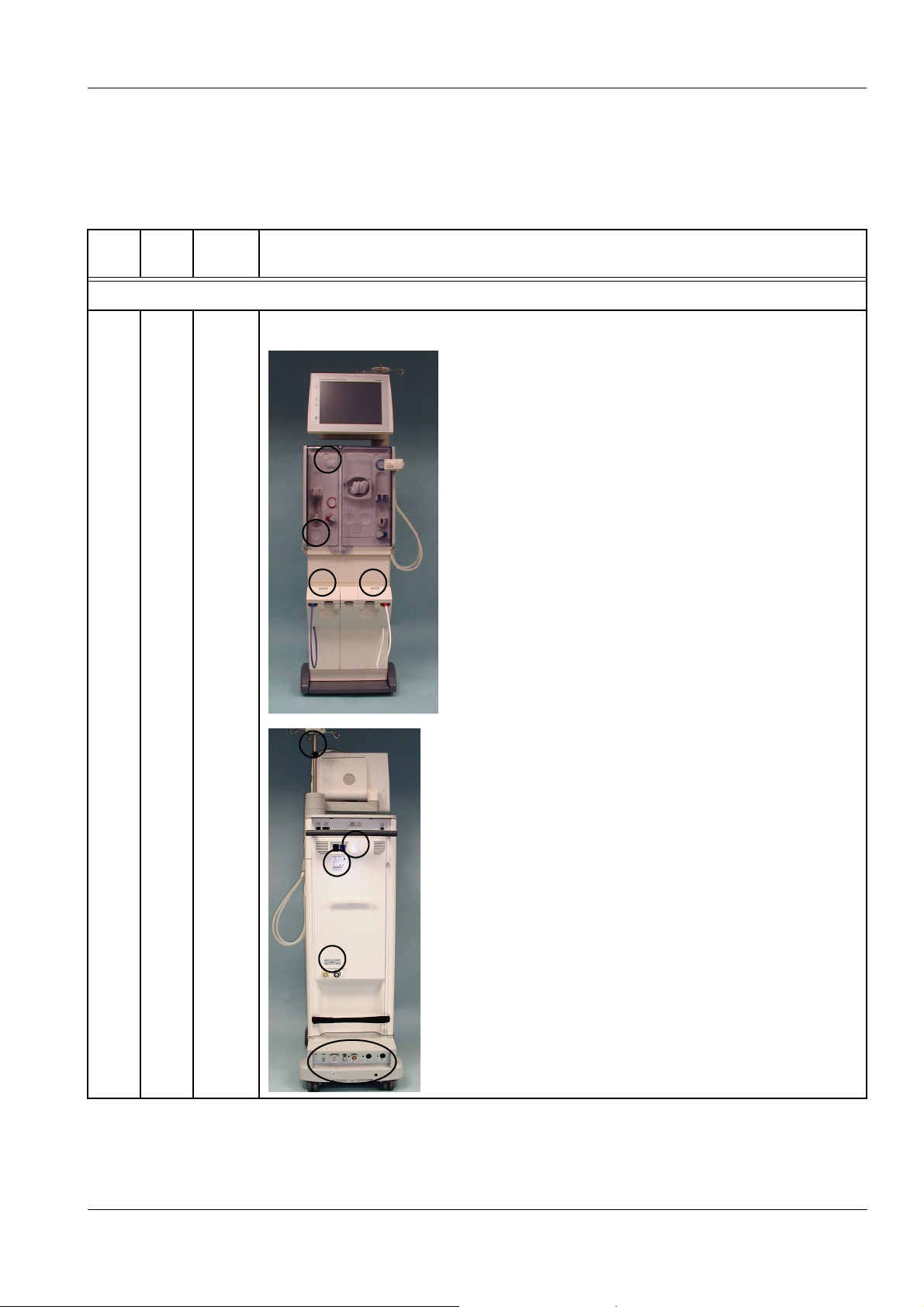
Chapter 6: TSC / TMC / Maintenance
6.3 Explanations on Technical Safety Checks, Technical Measurement Checks and Maintenance Procedures
TSC
TMC
TSC 1.1 Labels and labelings are present and legible.
MA No. Description
1 Visual inspections
Front view:
Applicable to ONLINEplus™
(option):
Substituate and rinse ports;
warning of scalding and
cauterizing risks.
Bicarbonate and concentrate
flaps; warning of scalding and
cauterizing risks.
Under bicarbonate flap:
reference to bibag
®
.
Rear view:
IV pole; maximum load
warning
Upper door area; warning of
tilting risk and
type label.
Disinfection connectors;
warning of cauterizing risk.
Hydraulics connector
Potential equalization label
ZKV/CDS 1, ZKV/CDS 2 and
BIC labels
Warning of scalding and
cauterizing risks.
Accumulator label
Fresenius Medical Care 5008 SM 1/08.04 6-11
Page 76

Chapter 6: TSC / TMC / Maintenance
TSC
TMC
TSC 1.2 The mechanical condition permits further safe use.
MA No. Description
There are no signs of damage or safety-reducing dirt.
To the right:
Under shunt interlock:
warning of scalding and
cauterizing risks.
Arrow labels on dialyzer
connectors.
On inside of door of dialysate
filter chamber;
Warning of scalding and
cauterizing risks.
On filter holders;
filter 1 and filter 2 labels;
warning of scalding and
cauterizing risks.
There must not be any damage or dirt affecting the electrical and mechanical
properties.
The following and other checks must be performed:
The monitor can be swivelled and stays in the position desired.
If its brakes are not locked, the carriage can be moved as desired. Check the brake.
Check EBM, concentrate connectors, filter chamber, and complete hydraulics (e.g.
leaks, corrosion, broken parts, loose parts).
TSC 1.3 No signs of damage on the power cord.
6-12 Fresenius Medical Care 5008 SM 1/08.04
Page 77

Chapter 6: TSC / TMC / Maintenance
TSC
TMC
TSC 1.4 Leakage sensors (S14, S35, EBM) inspected visually. Leakage sensors cleaned.
MA No. Description
Visually check leakage sensors for cleanliness and mechanical damage. The lacquer
coat of the sensors must not be damaged.
EBM
(leakage sensor)
S 14
(leakage sensor of filter
chamber)
S 35
(leakage sensor of
hydraulics)
TSC 1.5 Check valve for heat exchanger (A05) checked for proper function.
.
TSC 1.6 Rotor position (blood pump) checked. Rotor cleaned.
Visually check the rotor position (blood pump); rotor in proper stator. Line rollers and
guide pulleys are running smoothly.
MA 1.7 Dirty or shabby tubes replaced.
The following and other checks must be performed: Dialyzer supply and drain line
MA 1.8 Only applicable to CDS:
Bicarbonate and concentrate flaps checked for proper functioning.
Check engagement and microswitch.
MA 1.9 Seal of rinse chamber replaced.
Replace seal and iron ring.
Fresenius Medical Care 5008 SM 1/08.04 6-13
Page 78
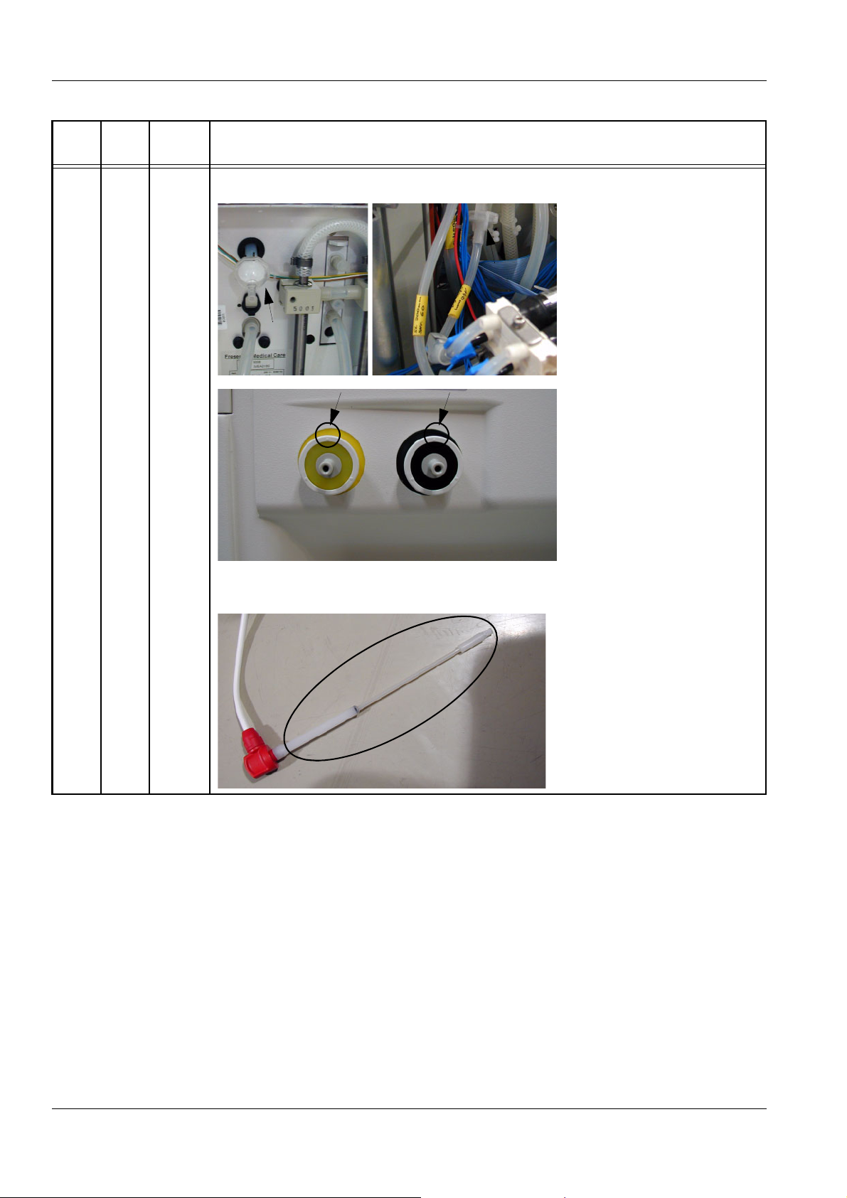
Chapter 6: TSC / TMC / Maintenance
TSC
TMC
MA No. Description
MA 1.10 Filters (F06, F08, F10, F11, F12, F13, F14, F15, F16) changed.
To the left:
F06
Hydrophobic filter
compressor
To the right:
F08
Filter of UF pump
To the left:
F10
Filter, disinfectant 1
To the right:
F16
Filter, disinfectant 2
Change filter including Oring. Grease O-rings before
installing them.
After installation, the mark
must be at the top.
F11
Suction rod with acetate filter
F12
Suction rod with bicarbonate
filter
6-14 Fresenius Medical Care 5008 SM 1/08.04
Page 79

Chapter 6: TSC / TMC / Maintenance
TSC
TMC
MA No. Description
To the right:
F15
Filter, CDS acid 1
Middle:
F14
Filter, CDS acid 2
To the left:
F15
Filter, CDS bicarbonate
Change filter including Oring. Grease O-rings before
installing them.
After installation, the mark
must be at the top.
MA 1.11 Filters (F01, F07) checked and changed if necessary.
To the right:
F01
Water inlet filter
MA 1.12 O-rings in dialyzer couplings replaced.
(Grease O-rings before installing them.)
MA 1.13 Disinfectant suction valves (V20, V34) replaced.
To the left:
F07
Dialysate filter
If necessary, change filter
including O-rings. Grease Orings before installing them.
After installation, the mark
must be at the top.
To the left:
V20
Disinfection valve 1
To the right:
V34
Disinfection valve 2
Fresenius Medical Care 5008 SM 1/08.04 6-15
Page 80

Chapter 6: TSC / TMC / Maintenance
TSC
MA No. Description
TMC
MA 1.14 Arterial and venous clamps checked.
1
2
3
2 General checks
TSC 2.1 Power failure alarm checked.
Permanent tone; alarm message: Power failure – Machine is battery-operated.
Pull off power plug to check the power failure alarm.
MA 2.2 Torque setting of monitor arm checked in all 3 axes.
Integrity of:
1 Grip handle
2 Valve tappet
3 Clamping and tappet
surfaces
MA 2.3 Every 4 years only:
Battery replaced.
3 Hydraulics unit
MA 3.1 Loading pressure of balancing chamber checked.
Monitor battery
Replace battery swiftly to
prevent loss of data.
Power supply unit battery
Turn on the hemodialysis
system after having replaced
the battery.
The current time is applied
after the next power-on.
Battery
Place the battery connection
cable in the appropriate
guides.
This pressure should be measured in the course of maintenance procedures.
Is done in the 5008 service program
6-16 Fresenius Medical Care 5008 SM 1/08.04
Page 81

Chapter 6: TSC / TMC / Maintenance
TSC
TMC
MA No. Description
MA 3.2 Level sensor (S17, S19) checked. (Not applicable to biBag.)
MA 3.3 Leakage sensors (S14, S35) inspected.
Visually check leakage sensors for cleanliness and mechanical damage. The lacquer
coat of the sensors must not be damaged.
EBM
(leakage sensor)
S 14
(leakage sensor of filter
chamber)
4 Dialysis mode
TSC 4.1 PT7 (temperature) checked at 37 °C. (Flow 500 ml/min)
Desired value: 36.8 °C to 37.2 °C (display on hemodialysis system)
Measure the reference temperature with an external measuring instrument.
Difference = Reference temperature minus PT7
Desired value – difference: –0.5 °C to +0.2 °C
TSC 4.2 CD7 (conductivity) checked.
Desired value: approx. 13.5 mS/cm to approx. 14.5 mS/cm
Measure the reference conductivity with an external measuring instrument.
Difference = Reference conductivity minus CD7
Desired value – difference: ±0.2 mS/cm
Fresenius Medical Care 5008 SM 1/08.04 6-17
Page 82

Chapter 6: TSC / TMC / Maintenance
TSC
TMC
MA No. Description
MA 4.3 Dialysate pressure checked.
In the service mode, select CALIBRATE.
Basic requirements:
The hemodialysis system must be closed.
The reference measuring instrument must be placed at the bottommost position of the
IV pole.
Dialyzer couplings must be connected to the reference instrument.
Flow on until dialysate lines and reference measuring instrument are free from air. Then
flow off.
4.3.1 Zero point S03/S07
Reference measuring instrument: 0 bar
Open the vent valve (UMED).
Using a syringe (filled with fluid) set a value of 0 bar, via the vent valve.
Check S03.
Desired value: +16 mbar to +76 mbar
Check S07.
Desired value: +16 mbar to +76 mbar
4.3.2 Slope S03/S07 (+)
Reference measuring instrument: +533 mbar (± 26 mbar)
Using a syringe (filled with fluid) set a value of +533 bar, via the vent valve.
Check S03.
Desired value: S03 = Display of reference measuring instrument + (+16 mbar to
+76 mbar)
Check S07.
Desired value: S07 = Display of reference measuring instrument + (+16 mbar to
+76 mbar)
4.3.3 Slope S03/S07 (–)
Reference measuring instrument: –533 mbar (± 26 mbar)
Using a syringe (filled with fluid) set a value of –533 bar, via the vent valve.
Check S03.
Desired value: S03 = Display of reference measuring instrument + (+16 mbar to
+76 mbar)
Check S07.
Desired value: S07 = Display of reference measuring instrument + (+16 mbar to
+76 mbar)
5 Extracorporeal components
MA 5.1 Zero point of arterial pressure display checked (standby operation)
Desired value: –5 mmHg to +5 mmHg
MA 5.2 Zero point of venous pressure display checked (standby operation)
Desired value: –5 mmHg to +5 mmHg
6-18 Fresenius Medical Care 5008 SM 1/08.04
Page 83

Chapter 6: TSC / TMC / Maintenance
TSC
TMC
TSC 5.3 Venous clamp checked.
MA No. Description
Basic requirements:
Blood lines inserted, standby operation.
Connect the arterial and the venous branch using the adapter fitting included.
Remove the line from the arterial clamp.
Clamp the blood line before the blood pump and on the venous drip chamber.
Connect the external pressure measuring instrument to the venous bubble catcher.
Connect the syringe and the one-way valve (if present) to the venous bubble catcher.
Pressure build-up – arterial
side:
Open the venous clamp.
Using a syringe, build up an
arterial pressure of 50 mmHg
to 100 mmHg.
Observe the arterial display
on the hemodialysis system.
Close the venous clamp.
Pressure build-up – venous
side:
Venous clamp closed.
Using a syringe, build up a
pressure of 2.5 bar to 2.7 bar.
Observe the display on the
external reference measuring
instrument.
Maximum pressure change within 3 minutes on the arterial pressure display of the
hemodialysis system ±5 mmHg.
Maximum pressure drop within 3 minutes on the display of the reference measuring
instrument –0.1 bar.
Fresenius Medical Care 5008 SM 1/08.04 6-19
Page 84

Chapter 6: TSC / TMC / Maintenance
TSC
TMC
6.1 biBag
TSC MA 6.1.1 O-ring at connector replaced.
6.2 Diasafe
TSC MA 6.2.1 Hydrophobic filter DIASAFEplus changed.
6.3 ONLINEplus
TSC 6.3.1 Rotor position (ONLINEplus) checked. Rotor cleaned.
MA No. Description
MA 5.4 Leakage sensors (EBM) cleaned.
Visually check leakage sensor for cleanliness and mechanical damage. The lacquer
coat of the sensors must not be damaged.
6 Options
EBM
(leakage sensor)
MA 6.3.2 Tube in tube squeeze valve replaced.
TSC 6.3.3 Hydrophobic filter changed.
TSC 6.3.4 O-rings at substituate port and rinse port replaced.
6.4 BPM
MA 6.4.1 Attachments of internal blood pressure module, printed circuit boards and cable
connections checked.
MA 6.4.2 Tube connection properly fixed to hemodialysis system.
MA 6.4.3 Tubings and cuffs checked for damage.
(damaged parts replaced)
TMC 6.4.4 Leakage test performed.
In the service mode, select DIAGNOSTICS. Select BPM from the DIAGNOSTICS
menu.
Basic requirements:
Tube and blood pressure cuff connected.
The blood pressure cuff must be placed on an artificial limb.
Pressure preselection 250 mmHg
Touch the Leakage test I/O button. (Test time approx. 4 minutes)
Read off the leakage rate from Info BPM. The maximum pressure leakage rate must be
≤6 mmHg/min.
6-20 Fresenius Medical Care 5008 SM 1/08.04
Page 85

Chapter 6: TSC / TMC / Maintenance
TSC
MA No. Description
TMC
TMC 6.4.5 Safety valve tested.
In the service mode, select DIAGNOSTICS. Select BPM from the DIAGNOSTICS
menu.
Basic requirements:
Tube and blood pressure cuff connected.
The blood pressure cuff must be placed on an artificial limb.
Pressure preselection 290 mmHg
Touch the Calibration test I/O button.
Once the pressure has reached approx. 290 mmHg, increase the pressure by slowly
pressing the blood pressure cuff. If 320 mmHg ±10 mmHg is exceeded, the cuff must
deflate immediately.
Touch the Status button in the Service menu. Touch the Error memory button. Touch
the BPM button. Check the error memory. Turn the hemodialysis system off and back
on again.
TMC 6.4.6 Blood pressure measurement performed.
Touch the SYSTEM button.
Touch the Blood pressure button. The blood pressure measurement starts.
After the measurement, check whether the values are plausible.
TMC 6.4.7 Calibration performed.
In the service mode, select DIAGNOSTICS. Select BPM from the DIAGNOSTICS
menu.
Remove tube and blood pressure cuff from the pressure connector.
Pressure
port
1
3
Connect a rigid metal vessel
(1), a pressure gauge (2), and
an aspirator bulb with drain
valve (3) to the pressure
connector.
Touch the Calibration test
2
I/O button.
Set the appropriate test
pressure using the drain
valve. Wait until the pressure
has stabilized. Check the test
pressure.
250 mmHg/ ±3 mmHg
200 mmHg / ±3 mmHg
150 mmHg / ±3 mmHg
100 mmHg / ±3 mmHg
50 mmHg / ±3 mmHg
6.5 Single Needle
TSC 6.5.1 Rotor position (Single Needle) checked. Rotor cleaned.
Fresenius Medical Care 5008 SM 1/08.04 6-21
Page 86

Chapter 6: TSC / TMC / Maintenance
TSC
TMC
TSC 7.1 Visual inspections performed according to item 1.
TSC 7.2 Protective earth resistance measured.
MA No. Description
7 Check – electrical safety
In Germany according to DIN VDE 0751-1, edition 10/2001.
In other countries, observe the local regulations!
– Labels and labelings are present and legible.
– The mechanical condition permits further safe use.
There are no signs of damage or dirt.
– No signs of damage on the power cord.
– Fuses accessible from the outside comply with the indicated values.
– Labels and labelings are present and legible.
No more than 0.3 ohms (with power cord)
The protective earth resistance must be checked on the following four measurement
points.
1. Measurement point: power
supply unit
2. Measurement point: shunt
door
6-22 Fresenius Medical Care 5008 SM 1/08.04
Page 87

Chapter 6: TSC / TMC / Maintenance
TSC
TMC
MA No. Description
3. Measurement point:
potential equalization
4. Measurement point: heater
Fresenius Medical Care 5008 SM 1/08.04 6-23
Page 88

Chapter 6: TSC / TMC / Maintenance
TSC
TMC
TSC 7.3 Leakage current (device leakage current) measured.
MA No. Description
L
N
PE
or
L
N
PE
L(N)
N(L)
M1
Differential current
measurement according to
figure C.6
Direct measurement
according to figure C.5
MD
Basic requirements:
Measurement of the protective earth resistance performed.
Perform the measurement in the dialysis or preparation mode with the system at
operating temperature.
Dialysate:
Dialysis temperature: ≥ 37 °C
Dialysate flow: ≥ 300 ml/min
Conductivity: ≥ 13 mS/cm
When performing a direct measurement, the following precautions also must be
observed:
The system must be insulated when installed.
All external connections must have been removed from the system.
The line voltage during the measurement will be recorded, as well as the maximum
device leakage current of both mains polarities, scaled to the nominal voltage of the
power supply. Maximum device leakage current: 500 µA
Example:
Line voltage during the measurement: 225 V
Device leakage current
for mains polarity 1: 180 µA
for mains polarity 2: 120 µA
Maximum value of both mains polarities: 180 µA
Nominal voltage of power supply: 230 V
Scaled to nominal voltage: 184 µA
(180 µA: 225V x 230V = 184 µA
Device leakage current < 500 µA: OK
6-24 Fresenius Medical Care 5008 SM 1/08.04
Page 89

Chapter 6: TSC / TMC / Maintenance
TSC
TMC
TSC MA 8.1 T1 test performed with all options.
TSC MA 8.2 Disinfection performed.
MA No. Description
Additional requirements:
If the device leakage current, scaled to the nominal voltage, is higher than 90 % of the
admissible alarm limit (450 µA), the last measured value or the first measured value
must additionally be considered for the rating.
If the device leakage current has considerably increased since the last measurement
or has continuously increased since the first measurement (creeping deterioration of
the insulation), or if the sum composed of the current value plus the difference since the
last measurement is > 500 µA, the measurement has not been completed successfully.
Example 1:
Device leakage current: 470 µA
Last measured value: 450 µA
470 + (470 – 450) = 470 + 20 = 490; is OK
Example 2:
Device leakage current: 470 µA
Last measured value: 390 µA
470 + (470 – 390) = 470 + 80 = 550; not passed
8 Final inspection and testing
Fresenius Medical Care 5008 SM 1/08.04 6-25
Page 90

Chapter 6: TSC / TMC / Maintenance
6-26 Fresenius Medical Care 5008 SM 1/08.04
Page 91

6.4 TSC / TMC Report
5008 TSC / TMC Report
Chapter 6: TSC / TMC / Maintenance
for the Technical Safety Checks and
Fresenius
Med ical
Care
Technical Measurement Checks
to be performed every two years (24 months)
The following inspections must be carried out by persons who are qualified to properly perform the
Technical Safety Checks and Technical Measurement Checks owing to their educational background
and training, their knowledge and experience gained in practice and who are not bound to any directions
with regard to their inspection activity.
Technician's name: Service report number:
Customer/Customer no.:
Inventory no.: Serial no.: Operating hours:
Machine type:
including option(s):
No. Description Measure
ment
value
1 Visual inspections
1.1 Labels and labelings are present and legible. T
1.2 The mechanical condition permits further safe use.
T
There are no signs of damage or safety-reducing dirt.
1.3 No signs of damage on the power cord. T
1.4 Leakage sensors checked visually. Leakage sensors cleaned. T
1.5 Check valve for heat exchanger (A05) checked for proper function. T
1.6 Rotor position (blood pump) checked. Rotor cleaned. T
2 General checks
2.1 Power failure alarm – continuous sound – display message: Emergency operation T
Fresenius Medical Care 5008 SM 1/08.04 6-27
Page 92

Chapter 6: TSC / TMC / Maintenance
No. Description Measure
ment
value
4 Dialysis mode
4.1 Temperature tested with reference instrument.
System / ref. ____/____ T
Desired temperature on temperature display
Difference between system temp. / ref. temp.: –0.5 to
+0.2 °C
4.2 Conductivity tested with reference instrument.
(The bibag
®
option requires connection of a bibag®.)
System CD / ref. CD ____/____ T
Difference between system CD / ref. CD: ≤±0.2 mS/cm
5 Extracorporeal components
5.3 Check of venous clamp performed.
T
A change in pressure must not exceed the following values within 3 minutes:
Arterial pressure display, maximum change in pressure: ±5 mmHg
Pressure display of reference measuring instrument, maximum pressure drop: –0.1 bar
6 Options
6.3 ONLINEplus
6.3.1 Rotor position (ONLINEplus) checked. Rotor cleaned. T
6.4 BPM
6.4.4
TMC
6.4.5
TMC
6.4.6 Safety valve tested.
Leakage test performed.
Pressure leakage rate: <6 mmHg/min ________
Calibration performed.
Pressure values / tolerance
250 mmHg / ±3 mmHg
200 mmHg / ±3 mmHg
150 mmHg / ±3 mmHg
100 mmHg / ±3 mmHg
50 mmHg / ±3 mmHg
System / ref.
System / ref.
System / ref.
System / ref.
System / ref.
____/____
____/____
____/____
____/____
____/____
T
T
T
System emptied at 320 mmHg ±10 mmHg ________
6.4.7
TMC
Blood pressure measurement performed.
Measured values are plausible.
T
6.5 Single Needle
6.5.1 Rotor position (Single Needle) checked. Rotor cleaned. T
6-28 Fresenius Medical Care 5008 SM 1/08.04
Page 93

Chapter 6: TSC / TMC / Maintenance
No. Description Measure
ment
value
7 Check – electrical safety
In Germany according to DIN VDE 0751-1, edition 10/2001.
In other countries, observe the local regulations!
7.1 Visual inspections performed according to item 1. T
7.2 Protective earth resistance maximum 0.3 ohms (with power cord) ______ Ω T
7.3 Leakage current measurement (device leakage current)
T Differential current measurement according to figure C.6
or
T Direct measurement according to figure C.5
Nominal voltage of power supply: __________ V
Device leakage current mains polarity 1 __________ µA
with line voltage __________ V
scaled to nominal voltage (maximum 500 µA, see Additional requirements) _____ µA
Device leakage current mains polarity 2 __________ µA
with line voltage __________ V
T
scaled to nominal voltage (maximum 500 µA, see Additional requirements) _____ µA
Test equipment used: ________________________
8 Final inspection and testing
8.1 T1 test performed with all options. T
8.2 Disinfection performed. T
Fresenius Medical Care 5008 SM 1/08.04 6-29
Page 94

Chapter 6: TSC / TMC / Maintenance
Date: Signature: Stamp:
The system has been released for further use. T Yes T No
Comments:
Date: Signature: Stamp:
6-30 Fresenius Medical Care 5008 SM 1/08.04
Page 95

7 Error Messages
The messages can be filed in the Message button.
Touch the X button to file the messages.
To retrieve the messages, touch the Message button.
If several messages are displayed, select the desired message.
The windows contain a brief description of the condition for the
technician and the required instructions to correct the problem.
Help can be displayed directly by touching the ? button in the window.
The associated Information window will be opened automatically.
Power failure and depleted battery
Screen failure
Chapter 7: Error Messages
Fresenius Medical Care 5008 SM 1/08.04 7-1
Page 96

Chapter 7: Error Messages
7-2 Fresenius Medical Care 5008 SM 1/08.04
Page 97

Chapter 8: Tools (Service Equipment)
8 Tools (Service Equipment)
Caution
Only for OCM (option):
The accuracy of the measuring equipment used during the calibration is
decisive for the accuracy of the OCM measurement.
The measuring equipment used for the calibration of the conductivity
must have an accuracy of 0.05 mS/cm in the temperature range of
35 °C to 39 °C.
We recommend using the measuring device UMED (part no. M32 403
1) available from Fresenius Medical Care.
HMED pressure measuring device with case
(set)
Part number: M30 770 1
UMED pressure measuring device with case
(set)
(conductivity, pressure, temperature)
Part number: M32 403 1
Fresenius Medical Care 5008 SM 1/08.04 8-1
Page 98

Chapter 8: Tools (Service Equipment)
Connection cable UMED - 5008
Part number: M35 152 1
Secutest VDE test device
(without printer module)
Part number: 631 064 1
Printer module (without illustration)
Part number: 630 652 1
Carrying bag (without illustration)
Part number: 630 648 1
PC Service Software
Part number: M35 016 1
8-2 Fresenius Medical Care 5008 SM 1/08.04
Page 99

Chapter 8: Tools (Service Equipment)
Graduated cylinder 100 ml
Part number: 510 085 1
ESD Service Kit
Part number: 630 387 1
ESD Workshop Kit
Part number: 630 388 1
Fresenius Medical Care 5008 SM 1/08.04 8-3
Page 100

Chapter 8: Tools (Service Equipment)
Toolcase 5008
Part number: M35 463 1
8-4 Fresenius Medical Care 5008 SM 1/08.04
 Loading...