


QED 6
Table of contents
 Loading...
PN 2204510
September 2007
© 2007 Fluke Corporation, All rights reserved. Printed in USA
All product names are trademarks of their respective companies.
QED 6
Defibrillator Analyzer
Users Guide

Warranty and Product Support
Fluke Biomedical warrants this instrument against defects in materials and
workmanship for one year from the date of original purchase. During the warranty period, we will repair or at our option replace, at no charge, a product
that proves to be defective, provided you return the product, shipping prepaid,
to Fluke Biomedical. This warranty covers the original purchaser only and is
not transferable. The warranty does not apply if the product has been damaged
by accident or misuse or has been serviced or modified by anyone other than
an authorized Fluke Biomedical service facility. NO OTHER WARRANTIES,
SUCH AS FITNESS FOR A PARTICULAR PURPOSE, ARE EXPRESSED
OR IMPLIED. FLUKE SHALL NOT BE LIABLE FOR ANY SPECIAL,
INDIRECT, INCIDENTAL OR CONSEQUENTIAL DAMAGES OR
LOSSES, INCLUDING LOSS OF DATA, ARISING FROM ANY CAUSE
OR THEORY.
This warranty covers only serialized products and their accessory items that
bear a distinct serial number tag. Recalibration of instruments is not covered
under the warranty
This warranty gives you specific legal rights and you may also have other
rights that vary in different jurisdictions. Since some jurisdictions do not allow
the exclusion or limitation of an implied warranty or of incidental or consequential damages, this limitation of liability may not apply to you. If any provision of this warranty is held invalid or unenforceable by a court or other decision-maker of competent jurisdiction, such holding will not affect the validity
or enforceability of any other provision.
07/07

Notices
All Rights Reserved
© Copyright 2007, Fluke Biomedical. No part of this publication may be reproduced, transmitted, transcribed, stored in a retrieval system, or translated into any language without the written
permission of Fluke Biomedical.
Copyright Release
Fluke Biomedical agrees to a limited copyright release that allows you to reproduce manuals and
other printed materials for use in service training programs and other technical publications. If
you would like other reproductions or distributions, submit a written request to Fluke Biomedical.
Unpacking and Inspection
Follow standard receiving practices upon receipt of the instrument. Check the shipping carton for
damage. If damage is found, stop unpacking the instrument. Notify the carrier and ask for an
agent to be present while the instrument is unpacked. There are no special unpacking instructions,
but be careful not to damage the instrument when unpacking it. Inspect the instrument for physical damage such as bent or broken parts, dents, or scratches.
Technical Support
For application support or answers to technical questions, either email
techservices@flukebiomedical.com
1-425-446-6945.
Claims
Our routine method of shipment is via common carrier, FOB origin. Upon delivery, if physical
damage is found, retain all packing materials in their original condition and contact the carrier
immediately to file a claim. If the instrument is delivered in good physical condition but does not
operate within specifications, or if there are any other problems not caused by shipping damage,
please contact Fluke Biomedical or your local sales representative.
or call 1-800- 648-7952 or
Standard Terms and Conditions
Refunds and Credits
Please note that only serialized products and their accessory items (i.e., products and
items bearing a distinct serial number tag) are eligible for partial refund and/or credit.
Nonserialized parts and accessory items (e.g., cables, carrying cases, auxiliary modules,
etc.) are not eligible for return or refund. Only products returned within 90 days from the date
of original purchase are eligible for refund/credit. In order to receive a partial refund/credit of a
product purchase price on a serialized product, the product must not have been damaged by the
customer or by the carrier chosen by the customer to return the goods, and the product must be
returned complete (meaning with all manuals, cables, accessories, etc.) and in “as new” and resalable condition. Products not returned within 90 days of purchase, or products which are not in
“as new” and resalable condition, are not eligible for credit return and will be returned to the customer. The Return Procedure (see below) must be followed to assure prompt refund/credit.
Restocking Charges
Products returned within 30 days of original purchase are subject to a minimum restocking fee of
15 %. Products returned in excess of 30 days after purchase, but prior to 90 days, are subject to a
minimum restocking fee of 20 %. Additional charges for damage and/or missing parts and accessories will be applied to all returns.

Return Procedure
All items being returned (including all warranty-claim shipments) must be sent freight-prepaid to
our factory location. When you return an instrument to Fluke Biomedical, we recommend using
United Parcel Service, Federal Express, or Air Parcel Post. We also recommend that you insure
your shipment for its actual replacement cost. Fluke Biomedical will not be responsible for lost
shipments or instruments that are received in damaged condition due to improper packaging or
handling.
Use the original carton and packaging material for shipment. If they are not available, we recommend the following guide for repackaging:
Use a double-walled carton of sufficient strength for the weight being shipped.
Use heavy paper or cardboard to protect all instrument surfaces. Use nonabrasive
material around all projecting parts.
Use at least four inches of tightly packed, industry-approved, shock-absorbent
Returns for partial refund/credit:
Every product returned for refund/credit must be accompanied by a Return Material Authorization (RMA) number, obtained from our Order Entry Group at 1-800-648-7952 or 1-425-446-
6945.
Repair and calibration:
To find the nearest service center, go to www.flukebiomedical.com/service
In the U.S.A.:
Cleveland Calibration Lab
Tel: 1-800-850-4606
Email: globalcal@flukebiomedical.com
Everett Calibration Lab
Tel: 1-888-993-5853
Email: service.status@fluke.com
In Europe, Middle East, and Africa:
Eindhoven Calibration Lab
Tel: +31-402-675300
Email: ServiceDesk@fluke.com
In Asia:
Everett Calibration Lab
Tel: +425-446-6945
Email: service.international@fluke.com
material around the instrument.
, or
Certification
This instrument was thoroughly tested and inspected. It was found to meet Fluke Biomedical’s
manufacturing specifications when it was shipped from the factory. Calibration measurements
are traceable to the National Institute of Standards and Technology (NIST). Devices for which
there are no NIST calibration standards are measured against in-house performance standards using accepted test procedures.
WARNING
Unauthorized user modifications or application beyond the published specifications may
result in electrical shock hazards or improper operation. Fluke Biomedical will not be responsible for any injuries sustained due to unauthorized equipment modifications.

Restrictions and Liabilities
Information in this document is subject to change and does not represent a commitment
by Fluke Biomedical. Changes made to the information in this document will be incorporated in new editions of the publication. No responsibility is assumed by Fluke Biomedical for the use or reliability of software or equipment that is not supplied by Fluke Biomedical, or by its affiliated dealers.
Manufacturing Location
The QED 6 Defibrillator Analyzer is manufactured in Everett, Washington by Fluke Biomedical, 6920 Seaway Blvd., Everett, WA, U.S.A.


Table of Contents
Chapter Title Page
1 Introduction and Specifications.............................................. 1-1
Description............................................................................................ 1-3
Unpacking and Inspection..................................................................... 1-4
General Safety Considerations.............................................................. 1-4
Symbols ............................................................................................ 1-4
Warnings and Cautions..................................................................... 1-5
Instrument Familiarization.................................................................... 1-6
Front Panel........................................................................................ 1-8
Back Panel ........................................................................................ 1-9
Upgrading the Analyzer........................................................................ 1-9
Specifications........................................................................................ 1-10
Accessories ........................................................................................... 1-14
2 Operation .................................................................................. 2-1
Introduction .......................................................................................... 2-3
Powering Up......................................................................................... 2-4
Adjusting Display Contrast................................................................... 2-9
Measuring Defibrillator Energy............................................................ 2-9
Evaluating Ability to Fire ..................................................................... 2-12
Defibrillator Pulse Playback ................................................................. 2-14
Viewing Oscilloscope Output............................................................... 2-14
Preparation for Viewing.................................................................... 2-14
Viewing a Test.................................................................................. 2-15
Measuring Synchronization .................................................................. 2-16
Generating Test Waveforms ................................................................. 2-18
Testing High Level Out ........................................................................ 2-20
Measuring Peak Voltage, Current, and Overshoot................................ 2-20
Measuring Charge Time (Models M and H)......................................... 2-21
Pacemaker (Non-Invasive) Testing....................................................... 2-22
Pacemaker Refractory Period Testing................................................... 2-24
Programming an Automatic Test Sequence.......................................... 2-26
Program Selection............................................................................. 2-27
Defib Setting..................................................................................... 2-28
Energy Limits ................................................................................... 2-28
Charge Time ..................................................................................... 2-28
i

QED 6
Users Guide
Sync Time ........................................................................................ 2-29
Peak.................................................................................................. 2-29
Overshoot ......................................................................................... 2-29
ECG Performance............................................................................. 2-30
Pacer................................................................................................. 2-30
Running an Automatic Test Sequence.................................................. 2-31
Printing the Analyzer Report Header ................................................... 2-32
Resetting the Analyzer to Factory Defaults.......................................... 2-35
Remote Operation ................................................................................ 2-36
Preparing for Serial Communications .............................................. 2-38
Ansur Software Control.................................................................... 2-39
3 Maintenance, Service, and Calibration .................................. 3-1
Maintenance ......................................................................................... 3-3
Avoiding Damage............................................................................. 3-3
Cleaning ........................................................................................... 3-3
Troubleshooting ................................................................................... 3-4
Service and Calibration ........................................................................ 3-5
ii

List of Tables
Table Title Page
1-1. Symbols ................................................................................................ 1-4
1-2. Front Panel Elements............................................................................ 1-8
1-3. Available QED 6 Models ...................................................................... 1-9
1-4. Standard Accessories ............................................................................ 1-14
1-5. Optional Accessories ............................................................................ 1-14
2-1. Available Waveforms ........................................................................... 2-10
2-2. Test Waveforms.................................................................................... 2-18
2-3. Autosequencing Defaults (Model H) .................................................... 2-26
2-4. Serial Port Wiring Configuration.......................................................... 2-37
2-5. Serial Cable Wiring Configuration ....................................................... 2-37
iii

QED 6
Users Guide
iv

List of Figures
Figure Title Page
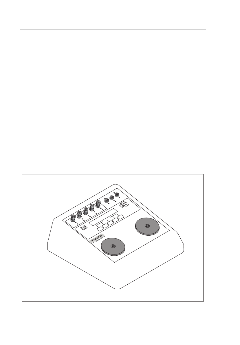
1-1. Analyzer Isometric View ...................................................................... 1-6
1-2. Analyzer Front Panel Layout ................................................................ 1-7
2-1. Analyzer Front Panel Display ............................................................... 2-3
2-2. Main Menu 1 Functions ........................................................................ 2-6
2-3. Main Menu 2 Functions ........................................................................ 2-7
2-4. Autosequence Menu Structure (Main Menu 2)..................................... 2-8
2-5. Defibrillator Energy Testing ................................................................. 2-11
2-6. QEDR Performance Tag....................................................................... 2-12
2-7. ECG Lead Configuration ...................................................................... 2-13
2-8. Sync Time Measurements..................................................................... 2-17
2-9. Connecting Pacemaker Output to Analyzer.......................................... 2-23
2-10. Manual Output with Header.................................................................. 2-33
2-11. Automatic Sequence Output with Header............................................. 2-34
v

QED 6
Users Guide
vi

Chapter 1
Introduction and Specifications
Contents Page
Description................................................................................... 1-3
Unpacking and Inspection ........................................................... 1-4
General Safety Considerations..................................................... 1-4
Symbols.................................................................................... 1-4
Warnings and Cautions ............................................................ 1-5
Instrument Familiarization........................................................... 1-6
Front Panel ............................................................................... 1-8
Back Panel................................................................................ 1-9
Upgrading the Analyzer............................................................... 1-9
Specifications............................................................................... 1-10
Accessories .................................................................................. 1-14
1-1

QED 6
Users Guide
1-2

Introduction and Specifications
Description
1
Description
The Fluke Biomedical QED 6 Defibrillator Analyzer, hereafter referred to as
the Analyzer, is a highly versatile and portable instrument. Regular testing of
defibrillators and pacemakers is critical to ensure safe and effective operation.
The Analyzer accurately verifies the output characteristics of all defibrillators
and tests the parameters of non-invasive pacemakers. The Analyzer is battery
operated and completely portable. Simple-to-use menu softkeys allow quick
access to tests.
The Analyzer measures:
• The delivered energy in joules (watt-seconds) from a defibrillator by
simulating the human body’s resistance
• The flow of current through that simulated resistance. The standard
resistance used by the Analyzer is 50 Ω. Defibrillator energy is measured
in one of two ranges: 0-100 joules, or 0-1000 joules.
Note
The defibrillator pulse waveform can be replayed via the ECG jacks
or paddle plates for viewing on a recorder, or on an oscilloscope for
greater detail.
• Synchronization time in milliseconds. This parameter is measured by
timing the firing delay from either the Q-wave (base) or R-wave (peak)
simulated by the Analyzer. The simulated waveform is present at both the
ECG jacks and the paddle plates.
• The peak voltage and peak current (amps) of the defibrillator pulse.
Overshoot voltage and current measurements of the defibrillator pulse are
calculated and displayed.
• The defibrillator’s charge time (the time it takes for a defibrillator to reach
its maximum charge setting).
Waveforms, including ECG, arrhythmias, and performance, help verify
monitor and recorder accuracy, and also test the automatic defibrillator’s
ability to recognize the maximum charge and fire.
All waveforms are present at the ECG jacks, the paddle plates and scope
output. Utilities allow the setting of Serial RS232 communication parameters
to download results to a printer or computer. Display contrast can be adjusted
to obtain the best view of the LCD display.
1-3

QED 6
Users Guide
Unpacking and Inspection
Use the following checklist when unpacking the Analyzer to check for damage
during shipment. If the Analyzer has been damaged, call your Fluke
Biomedical representative immediately. If you must return the Analyzer to
Fluke for service, follow the procedure given under Packing Instructions.
• Perform a visual inspection to ensure the front panel and case are intact.
• Check the LCD display to ensure that it is unbroken.
• Place the Analyzer on a level surface and power up the instrument. If the
message, WARNING - LOW BATTERY!! appears on the display, replace
the battery.
General Safety Considerations
Read the Users Manual before operating the Analyzer.
Symbols
Table 1-1 describes the symbols associated with the Analyzer.
Table 1-1. Symbols
Symbol Description
W Important information; refer to manual.
~
Do not dispose of this product as unsorted municipal waste. Go
to Fluke’s website for recycling information.
; Conforms to relevant Australian EMC requirements
X Hazardous voltage
P Conforms to European Union directives
IEC Measurement Category I – CAT I equipment designed to
CAT I
1-4
protect against transients in equipment on circuits not directly
connected to MAINS. Under no circumstances should the
terminals of the Analyzer be connected to any MAINS voltage.

Introduction and Specifications
General Safety Considerations
Warnings and Cautions
A Warning identifies hazardous conditions and actions that could cause
bodily harm or death.
A Caution identifies conditions and actions that could damage the Analyzer,
the equipment under test, or cause permanent loss of data.
XW Warning
To avoid possible electrical shock or personal injury,
follow these guidelines:
• Use this Analyzer only in the manner specified by the
manufacturer or the protection provided may be
impaired.
• Do not use the product if it operates abnormally.
• Remove all test leads and disconnect the battery
eliminator before replacing the battery.
• Do not use the product around explosive gases or in
wet or dusty environments.
• Inspect the defibrillator daily. Examine the paddles,
lead wires, and power cord for cracks and frays.
1
• If the defibrillator is line powered, be sure that it is
plugged into a grounded receptacle. Do not touch the
electrical contact surfaces of the defibrillator paddles.
• Grip one paddle handle firmly in each hand. Apply to
the Analyzer plates. Keep the paddles firmly depressed
to prevent arcing that can cause injury to the operator
and/or damage to the Analyzer or defibrillator.
• Do not touch the contact plates on the Analyzer when
the defibrillator paddles are being pressed onto the
plates. Do not use any electrical paste or pads when
testing a defibrillator with the Analyzer.
1-5
QED 6
Users Guide
W Caution
To avoid damage to the Analyzer or adverse affects on its
performance, follow these guidelines:
• Do not expose the system to temperature extremes.
Ambient temperatures should remain between 0 °C and
40 °C, with a relative humidity less than 90 %. System
performance may be adversely affected if temperatures
fluctuate above or below this range.
• Clean the Analyzer only by wiping it down with a clean,
lint-free cloth dampened with a mild detergent solution.
Do not spray liquid directly on or immerse the unit.
Instrument Familiarization
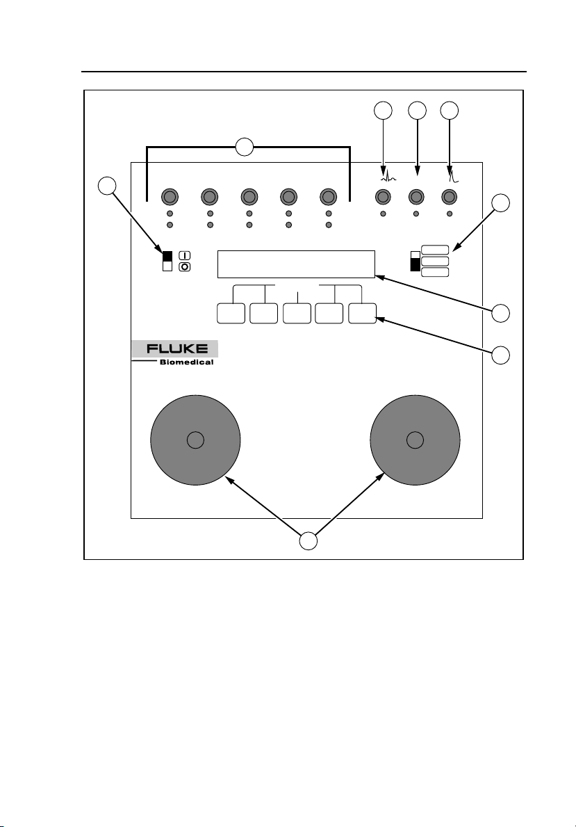
Figure 1-1 is an isometric illustration of the Analyzer, and the Front Panel
Layout is shown in Figure 1-2.
1-6
DEFIB
BATTERY / 9VDC
RA
ECG
RS-232 / 10101
V
C
LL
F
LA
L
RL
N
R
SOFTKEYS
QED-6
DEFIBRILLATOR ANALYZER
STERNUM (-)
PACER
1000 j
100 j
Figure 1-1. Analyzer Isometric View
APEX (+)
fcf013.eps
Introduction and Specifications
Instrument Familiarization
2 3 4
1
BATTERY / 9VDC RS-232 / 10101
6
LL
LA
RL
RA
R
L
N
QED-6
DEFIBRILLATOR ANALYZER
F
SOFTKEYS
V
C
ECG
DEFIB
PACER
1000 j
100 j
1
5
7
8
STERNUM (-)
APEX (+)
9
fcf017.eps
Figure 1-2. Analyzer Front Panel Layout
1-7

QED 6
Users Guide
Front Panel
The front panel of the Analyzer includes the elements described in Table 1-2.
Table 1-2. Front Panel Elements
Number Element Function
A
B
C
D
E Range switch
F Power switch Enables the Analyzer (I = ON, O = OFF).
G
H Five softkeys
Universal ECG
jacks
High Level
ECG Banana
jack
Common
Banana jack
Defib Scope
Out Banana
jack
LCD display:
24 characters x
2 lines.
Utilize AHA and International color coding,
allowing for waveform output to monitor/recorder.
Provides 1 volt peak output of the selected
waveform.
Provides ground for the “High Level ECG” and
“Defib Scope Out” jacks.
Provides pulse output to an oscilloscope.
Allows for defibrillator settings from 0 to 1000
joules (high), for power below 0-100 joules (low)
for increased accuracy, and a PACER range
setting for pacer output measurements.
The upper line of the LCD display provides
messages and test results, while the bottom line
displays menu choices.
Used to select the desired function highlighted on
the lower line of the display.
1-8
I
Two nickelplated
Defibrillator
Paddle Plates
Available for defibrillator paddle contact. All
waveforms are present at the paddle plates
simultaneously with the ECG jacks.

Introduction and Specifications
Upgrading the Analyzer
1
Back Panel
The Back Panel includes a battery holder that houses a 9-volt alkaline battery,
and a dc battery eliminator jack. An RS232 D-9-pin serial port allows
communications to a computer, serial printer, or other Fluke test equipment.
Upgrading the Analyzer
A number of pre-configured Analyzer models are available. In addition, older
models may be upgraded by contacting the Fluke Biomedical Service Center.
Available Analyzer models are listed in Table 1-3.
Table 1-3. Available Analyzer Models
Model Characteristics
QED 6
QED 6M
QED 6H
Base unit. Features output energy, synchronization time, peak
measurements, bi-directional RS232.
Features output energy, sync time, peak measurements,
overshoot, bi-directional RS232, waveforms, charge time
measurements, 28 programmable autosequences.
Output energy, sync time, peak measurements, overshoot, bidirectional RS232, waveforms, charge time measurements, 28
programmable autosequences, pacer output measurements
and pacer refractory period measurements.
1-9

QED 6
Users Guide
Specifications
The following are specifications for the Analyzer. Please contact your Fluke
Biomedical service representative for more information regarding the device
specifications.
General
Display.....................................................................2-line x 24-character LCD
Power ......................................................................One 9 V Alkaline (Duracell MN1604 or
Weight ....................................................................4.54 lb
Dimensions .............................................................26.67 x 24.13 x 10.16 cm
Environmental Operating Specs
Storage Temperature ..........................................-25 to 50 °C
Operating Temperature .......................................0 to 40 °C
Maximum Humidity..............................................90 % Relative Humidity
Output Power Measurement
Load Resistance......................................................50 Ω ±1 % non-inductance
Range
1000 J..................................................................0-1000.0 J
100 J....................................................................0-100.0 J
Resolution................................................................0.1 J
Max. Vage
1000 J..................................................................5500 V
100 J....................................................................1750 V
Max. Current
1000 J..................................................................110 A
100 J....................................................................35 A
Measurement...........................................................1000 J: 66 ±5 V
Trip Levels...............................................................100 J: 20 ±5 V
Pulse Width .............................................................1-50 ms
Accuracy
1000 J Range ......................................................±2 % of reading
100-1000 J .......................................................... ±2 Js
100 J Range ........................................................±2 % of reading
supertwist alphanumeric
equivalent); 12 hours continuous
operation; low battery indication; 9 V
battery eliminator input.
(< 10 µH), 160 W
±0.1 J
1-10
Loading...