

Page 1
®
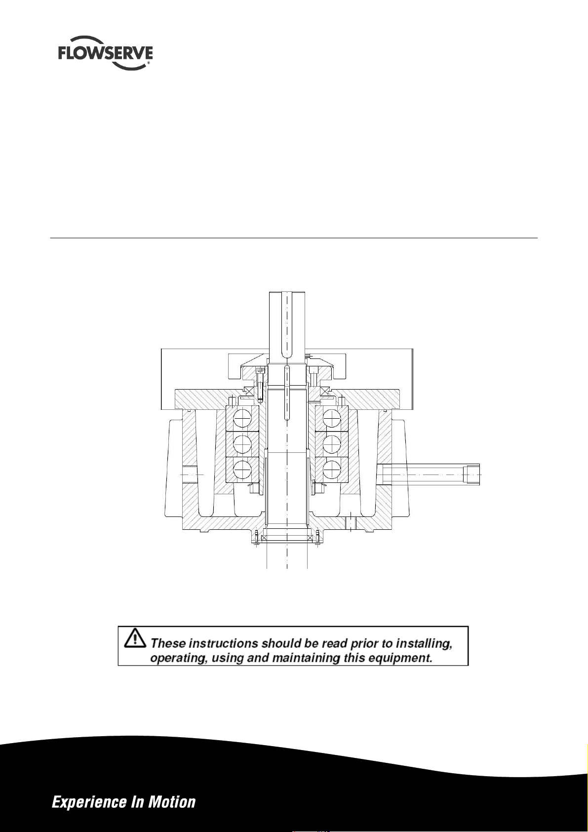
Worthington
N-Series of Thrust Pot
for Vertical, Multistage Pumps
USER INSTRUCTIONS
Installation
Operation
Original Instructions
PCN= 26999948 07-14 (E)
Maintenance
Page 2

N-SERIES OF THRUST POT USER INSTRUCTIONS ENGLISH 07/14
CONTENTS
PAGE
1.0 INTRODUCTION AND SAFETY ............................ 3
1.1 G
ENERAL
1.2 CE
1.3 D
ISCLAIMER
1.4 C
OPYRIGHT
1.5 D
UTY CONDITIONS
1.6 S
AFETY
................................................................. 3
MARKING AND APPROVALS
................................ 3
............................................................. 3
............................................................. 3
................................................... 3
.................................................................... 4
2.0 TRANSPORT AND STORAGE ............................. 7
2.1 C
ONSIGNMENT RECEIPT AND UNPACKING
2.2 H
ANDLING
2.3 L
IFTING
2.4 S
TORAGE
2.5 R
ECYCLING AND END OF PRODUCT LIFE
................................................................ 7
.................................................................... 7
................................................................. 7
............... 7
................. 7
3.0 COMMISSIONING START-UP, OPERATION
AND SHUTDOWN .......................................................... 8
3.1 P
UMP LUBRICANTS
3.2 O
PERATION
.................................................. 8
............................................................ 10
4.0 MAINTENANCE ..................................................... 10
4.1 G
ENERAL
4.2 M
AINTENANCE SCHEDULE
4.3 S
PARE PARTS
4.4 R
ECOMMENDED SPARES
4.6 D
ISASSEMBLY
4.7 A
SSEMBLY
............................................................... 10
..................................... 10
........................................................ 10
....................................... 11
........................................................ 12
............................................................. 12
5.0 FAULTS; CAUSES AND REMEDIES ................ 13
6.0 PARTS LIST AND DRAWINGS ........................... 14
6.1 A
6.2 A
6.3 A
SSEMBLY
SSEMBLY
SSEMBLY
0N-1N ................................................. 14
3N-7N ................................................. 15
8N ....................................................... 16
7.0 CERTIFICATION .................................................... 17
8.0 OTHER RELEVANT DOCUMENTATION AND
MANUALS ..................................................................... 17
8.1 S
UPPLEMENTARY USER INSTRUCTIONS
8.2 C
HANGE NOTES
8.3 A
DDITIONAL SOURCES OF INFORMATION
8.4 A
BBREVIATIONS
..................................................... 17
..................................................... 18
................ 17
.............. 17
Page 2 of 20
Page 3

N-SERIES OF THRUST POT USER INSTRUCTIONS ENGLISH 07/14
1.0 INTRODUCTION AND SAFETY
instructions. Where applicable this document
incorporates information relevant to these Directives.
To establish Approvals and if the product itself is CE
Marked check the serial number plate and the
Certification.
1.1 General
These Instructions must always be kept
close to product's operating location or directly
with the product.
Flowserve's products are designed, developed and
manufactured with state-of-the-art technologies in
modern facilities. The unit is produced with great care
and commitment to continuous quality control,
utilizing sophisticated quality techniques, and safety
requirements.
Flowserve is committed to continuous quality
improvement and being at service for any further
information about the product in its installation and
operation or about its support products, repair and
diagnostic services.
These instructions are intended to facilitate
familiarization with the product and its permitted use.
Operating the product in compliance with these
instructions is important to help ensure reliability in
service and avoid risks. The instructions may not take
into account local regulations; ensure such regulations
are observed by all, including those installing the
product. Always coordinate repair activity with
operations personnel, and follow all plant safety
requirements and applicable safety and health
laws/regulations.
These instructions must be read prior to
installing, operating, using and maintaining the
equipment in any region worldwide. The equipment
must not be put into service until all the conditions
relating to safety, noted in the instructions, have
been met. Failure to follow and apply the present
user instructions is considered to be misuse.
Personal injury, product damage, delay or failure
caused by misuse are not covered by the Flowserve
warranty.
1.3 Disclaimer
Information in these User Instructions is believed to
be complete and reliable. However, in spite of all of
the efforts of Flowserve Corporation to provide
comprehensive instructions, good engineering and
safety practice should always be used.
Flowserve manufactures products to exacting
International Quality Management System Standards
as certified and audited by external Quality
Assurance organizations. Genuine parts and
accessories have been designed, tested and
incorporated into the products to help ensure their
continued product quality and performance in use. As
Flowserve cannot test parts and accessories sourced
from other vendors the incorrect incorporation of such
parts and accessories may adversely affect the
performance and safety features of the products. The
failure to properly select, install or use authorized
Flowserve parts and accessories is considered to be
misuse. Damage or failure caused by misuse is not
covered by Flowserve's warranty. In addition, any
modification of Flowserve products or removal of
original components may impair the safety of these
products in their use.
1.4 Copyright
All rights reserved. No part of these instructions may
be reproduced, stored in a retrieval system or
transmitted in any form or by any means without prior
permission of Flowserve.
1.5 Duty conditions
This product has been selected to meet the
specifications of your purchaser order. The
acknowledgement of these conditions has been sent
separately to the Purchaser. A copy should be kept
with these instructions.
1.2 CE marking and approvals
It is a legal requirement that machinery and
equipment put into service within certain regions of
the world shall conform with the applicable CE
Marking Directives covering Machinery and, where
applicable, Low Voltage Equipment, Electromagnetic
Compatibility (EMC), Pressure Equipment Directive
(PED) and Equipment for Potentially Explosive
Atmospheres (ATEX).
Where applicable the Directives, and any additional
Approvals, cover important safety aspects relating to
machinery and equipment and the satisfactory
provision of technical documents and safety
Page 3 of 20
The product must not be operated beyond
the parameters specified for the application. If
there is any doubt as to the suitability of the
product for the application intended, contact
Flowserve for advice, quoting the serial number.
If the conditions of service on your purchase order
are going to be changed (for example liquid pumped,
temperature or duty) it is requested that the user
seeks Flowserve´s written agreement before start up.
Page 4
N-SERIES OF THRUST POT USER INSTRUCTIONS ENGLISH 07/14
1.6 Safety
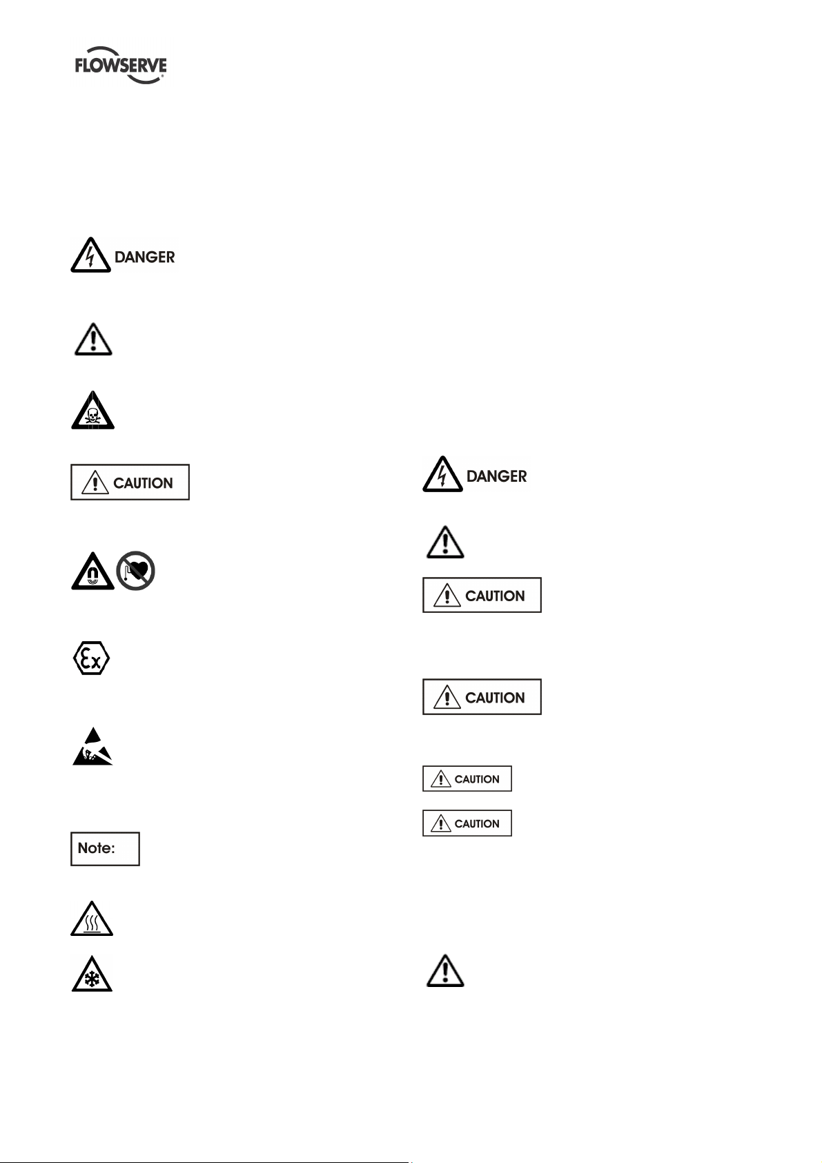
1.6.1 Summary of safety markings
These user instructions contain specific safety
markings where non-observance of an instruction
would cause hazards. The specific safety markings
are:
This symbol indicates electrical safety instructions
where non-compliance will involve a high risk to
personal safety or the loss of life.
This symbol indicates safety instructions
where non-compliance would affect personal safety
and could result in loss of life.
This symbol indicates "hazardous and toxic
fluid" safety instructions where non-compliance would
affect personal safety and could result in loss of life.
instructions where non-compliance will involve some
risk to safe operation and personal safety and would
damage the equipment or property.
field" safety instructions where non-compliance would
affect personal safety, pacemakers, instruments or
stored data sensitive to magnetic fields.
This symbol indicates explosive atmosphere
marking according to ATEX. It is used in safety
instructions where non-compliance in the hazardous
area would cause the risk of an explosion.
This symbol is used in safety instructions to
remind not to rub non-metallic surfaces with a dry
cloth; ensure the cloth is damp. It is used in safety
instructions where non-compliance in the hazardous
area would cause the risk of an explosion.
indicates an important instruction in the assembly
process.
This symbol indicates potential risks
connected with extremely high temperatures.
This symbol indicates safety
This symbol indicates "strong magnetic
The sign is not a safety symbol but
1.6.2 Personnel qualification and training
All personnel involved in the operation, installation,
inspection and maintenance of the unit must be
qualified to carry out the work involved. If the
personnel in question do not already possess the
necessary knowledge and skill, appropriate training
and instruction must be provided. If required the
operator may commission the manufacturer / supplier
to provide applicable training.
Always co-ordinate repair activity with operations and
health and safety personnel, and follow all plant
safety requirements and applicable safety and health
laws/regulations.
1.6.3 Safety action
This is a summary of conditions and actions to
help prevent injury to personnel and damage to
the environment and to equipment. For products
used in potentially explosive atmospheres
section 1.6.4 also applies.
NEVER DO MAINTENANCE WORK WHILST THE
UNIT IS CONNECTED TO POWER
GUARDS MUST NOT BE REMOVED WHILE
PUMP IS OPERATIONAL
MOTOR ROTATION WITH COUPLING ELEMENT/
PINS REMOVED
Starting in reverse direction of rotation will damage
the pump.
LUBRICATION (See section 3.0, Commissioning,
startup, operation and shutdown.)
ABNORMALLY HIGH OR LOW FLOW RATES
Operating at a flow rate higher than normal or at a flow
rate with no back pressure on the pump may overload
the motor and cause cavitation. Low flow rates may
cause a reduction in pump/bearing life, overheating of
the pump, instability and cavitation/vibration.
ONLY CHECK DIRECTION OF
ENSURE CORRECT
NEVER RUN THE PUMP DRY
DO NOT RUN THE PUMP AT
This symbol indicates potential risks
connected with extremely low temperatures.
Many precision parts have sharp corners and the
wearing of appropriate safety gloves and equipment
is required when handling these components. To lift
heavy pieces above 25 kg (55 lbs) use a crane
Page 4 of 20
HANDLING COMPONENTS
Page 5
Temperature class
N-SERIES OF THRUST POT USER INSTRUCTIONS ENGLISH 07/14
corresponding to the mass and in accordance with
current local regulations.
HOT AND COLD PARTS
If hot or freezing components or auxiliary heating
supplies can present a danger to operators, they
must be shielded to avoid accidental contact. If
complete protection is not possible, the machine
access must be limited to maintenance staff only.
Bearing housings must not be insulated
and drive motors and bearings may be hot.
If the temperature is greater than 80 °C (175 °F) o r
below -5 °C (20 °F) in a restricted zone, or
exceeds local regulations, action as above shall
be taken.
1.6.4 Products used in potentially explosive
atmospheres
Measures are required to:
• Avoid excess temperature
• Prevent dry running
• Prevent the generation of sparks
• Maintain the pump to avoid hazard
The following instructions for pumps and pump units
when installed in potentially explosive atmospheres
must be followed to help ensure explosion protection.
For ATEX, both electrical and non-electrical equipment
must meet the requirements of European Directive
94/9/EC. Always observe the regional legal Ex
requirements eg Ex electrical items outside the EU may
be required certified to other than ATEX eg IECEx, UL.
1.6.4.1 Scope of compliance
Use equipment only in the zone for which it is
appropriate. Always check that the driver, drive
coupling assembly, seal and pump equipment are
suitably rated and/or certified for the classification of the
specific atmosphere in which they are to be installed.
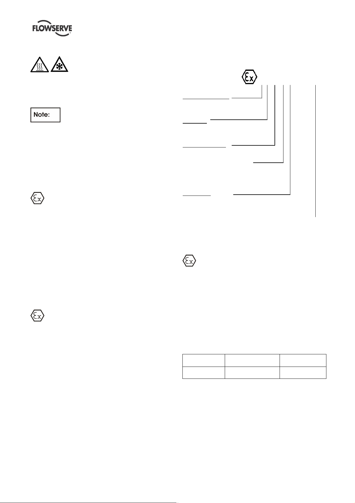
1.6.4.2 Marking
An example of ATEX equipment marking is shown
below. The actual classification of the pump will be
engraved on the nameplate.
II 2 GD c IIC135ºC (T4)
Equipment Group
I = Mining
II = Non-mining
Category
2 or M2 = High level protection
3 = normal level of protection
Gas and/or Dust
G = Gas; D= Dust
c = Constructional safety
(in accordance with EN13463-5)
b = Control of ignition source
(in accordance with EN13463-6)
Gas Group
IIA – Propane (Typical)
IIB – Ethylene (Typical)
IIC – Hydrogen (Typical)
Maximum surface temperature (Temperature Class)
(see section 1.6.4.3)
1.6.4.3 Avoiding excessive surface
temperatures
ENSURE THE EQUIPMENT TEMPERATURE
CLASS IS SUITABLE FOR THE HAZARD ZONE
Pumps have a temperature class as stated in the
ATEX Ex rating on the nameplate. These are based
on a maximum ambient of 40 ºC (104 ºF); refer to
Flowserve for higher ambient temperatures.
The surface temperature on the pump is influenced
by the temperature of the liquid handled. The
maximum permissible liquid temperature depends on
the temperature class and must not exceed the
values in the table that follows.
to EN13463-1
T6
T5
* The table only takes the ATEX temperature class into consideration.
Pump design or material, as well as component design or material,
may further limit the maximum working temperature of the liquid.
Maximum surface
temperature permitted
85 °C (185 °F)
100 °C (212 °F)
Temperature limit of
liquid handled *
Consult Flowserve
Consult Flowserve
The temperature rise at the seals and bearings and
due to the minimum permitted flow rate is taken into
account in the temperatures stated.
The responsibility for compliance with the
specified maximum liquid temperature is with the
plant operator.
Temperature classification “Tx” is used when the
liquid temperature varies and the pump could be
Page 5 of 20
Page 6

N-SERIES OF THRUST POT USER INSTRUCTIONS ENGLISH 07/14
installed in different hazarous atmospheres. In this
case the user is responsible for ensuring that the
pump surface temperature does not exceed that
permitted in the particular hazardous atmosphere.
If an explosive atmosphere exists during the
installation, do not attempt to check the direction of
rotation by starting the pump unfilled. Even a short
run time may give a high temperature resulting from
contact between rotating and stationary components.
Where there is any risk of the pump being run against
a closed valve generating high liquid and casing
external surface temperatures, fit an external surface
temperature protection device.
Avoid mechanical, hydraulic or electrical overload by
using motor overload trips, temperature monitor or a
power monitor and make routine vibration monitoring
checks.
In dirty or dusty environments, make regular checks
and remove dirt from areas around close clearances,
bearing housings and motors.
1.6.4.4 Preventing dry running
adversely affect the ambient conditions. Where there
is a risk from such tools or materials, maintenance
must be conducted in a safe area.
It is recommended that a maintenance plan and
schedule is adopted. (See section 4.0,
Maintenance.)
ENSURE THAT THE THRUST POT IS
PROPERLY FILLED ANS DOES NOT RUN DRY
Ensure that the oil level is as per section 3.1.4.
The bearing temperature shall be monitored by
means of a PT 100, surface contact type.
1.6.4.5 Preventing sparks
To prevent a potential hazard from mechanical
contact, the coupling guard must be non-sparking.
To avoid the potential hazard from random induced
current generating a spark, the baseplate must be
properly grounded.
Avoid electrostatic charge: do not rub non-metallic
surfaces with a dry cloth; ensure cloth is damp.
For ATEX application sthe coupling must be selected
to comply with 94/9/EC. Correct coupling alignment
must be maintained.
1.6.4.6 Maintenance to avoid the hazard
CORRECT MAINTENANCE IS REQUIRED TO
AVOID POTENTIAL HAZARDS WHICH GIVE A
RISK OF EXPLOSION
The responsibility for compliance with maintenance
instructions is with the plant operator.
To avoid potential explosion hazards during
maintenance, the tools, cleaning and painting
materials used must not give rise to sparking or
Page 6 of 20
Page 7

N-SERIES OF THRUST POT USER INSTRUCTIONS ENGLISH 07/14
2.0 TRANSPORT AND STORAGE
2.1 Consignment receipt and unpacking
Immediately after receipt of the equipment it must be
checked against the delivery/shipping documents for
its completeness and that there has been no damage
in transportation. Any shortage and/or damage must
be reported immediately to Flowserve Pump Division
and must be received in writing within one month of
receipt of the equipment. Later claims cannot be
accepted.
Check any crate, boxes or wrappings for any
accessories or spare parts that may be packed
separately with the equipment or attached to side
walls of the box or equipment.
Each product has a unique serial number. Check
that this number corresponds with that advised and
always quote this number in correspondence as well
as when ordering spare parts or further accessories.
2.2 Handling
Boxes, crates, pallets or cartons may be unloaded
using fork lift vehicles or slings dependent on their
size and construction.
2.3 Lifting
Make sure that hazardous substances are
disposed of safely and that the correct personal
protective equipment is used. The safety
specifications must be in accordance with the current
regulations at all times.
A crane must be used for all pump sets in
excess of 25 kg (55 lb.). Fully trained personnel must
carry out lifting, in accordance with local regulations.
Before lifting the driver alone, refer to the
manufacturer’s instructions.
2.4 Storage
Store the unit in a clean, dry location
away from vibration. Leave protective covers and
plugs in place to keep dirt and other foreign material
out of the unit. Turn shaft at intervals to prevent false
brinelling of the bearings.
The unit may be stored as above for up to 6 months.
Consult Flowserve for preservative actions when a
longer storage period is needed.
2.5 Recycling and end of product life
At the end of the service life of the product or its
parts, the relevant materials and parts should be
recycled or disposed of using an environmentally
acceptable method and local requirements. If the
product contains substances that are harmful to the
environment, these should be removed and disposed
of in accordance with current regulations. This also
includes the liquids and/or gases that may be used in
the "seal system" or other utilities.
Page 7 of 20
Page 8

N-SERIES OF THRUST POT USER INSTRUCTIONS ENGLISH 07/14
3.0 COMMISSIONING START-UP,
OPERATION AND SHUTDOWN
These operations must be
carried out by fully qualified personnel.
3.1 Pump Lubricants
3.1.1 Lubrication
The bearing housing shall be filled with proper
lubricating oil prior to start up. If the pump will be
started after a longer storage period, the bearing
housing should be first flushed and cleaned with
gasoline. It is not necessary to remove the
preservation oil as this will mix up thoroughly with the
lubrication oil.
Lubrication is provided by the pumping effect of the
rotating ball bearings. Maintaining the correct oil level
(middle of the oil sight glass) ensures that the lower
ball bearing is covered with oil.
As option a ¼” NPT connection for a purge oil mist
lubrication is provided (refer to General Arrangement
Drawing).
For recommended lubricating oils refer to the
lubrication table.
3.1.2 Purge oil mist lubrication
For preventing, that dirt or humidity get into the bearing
housing, this pump is equipped with a ¼“ NPT
connection for air or nitrogen supply.
Also at standstill the air or nitrogen supply shall be
maintained.
The pressure shall be between
0.01 bar (0.14 psi) and 0.02 bar (0.29 psi), otherwise
you have to consider an oil leakage and as a result a
bearing damage .
The provided flow rate shall be 0,1 SCFM.
The supplied air or nitrogen shall be clean and dry.
3.1.3 Oil change
After first start up, the oil shall be changed after 200
service hours.
Every further oil change shall take place after about
2000 service hours or at least every 6 month.
3.1.4 Oil level
The correct oil level is in the middle of the oil sight glass
and shall be checked when pump is not in operation.
Periodically check if the lubricating oil is mixed with any
condensed water. Careful opening of the oil drain
during a stop of the pump will show any water.
During operation the level will decrease
due to circulation of the oil through the bearings.
A too high oil level will result in higher bearing
temperatures and therefore poorer lubrication.
3.1.5 Oil quality
Oil used for lubrication should only be of high quality.
The viscosity of the oil at working temperature must
be at least 10 cSt. The pouring point of the oil must
be in accordance with the lowest expected
temperature of the bearing housing during a stop of
the pump. For recommended lubricating oils refer to
the lubrication table.
Having selected the corresponding oil quality the
actual oil temperature at the bearing housing must be
checked after two service hours of the pump.
Considering this measured oil temperature the actual
viscosity must be determined by using the data sheet
of the oil, to verify the minimum required viscosity of
10 cSt. Do not forget, the oil temperature in the
bearing itself is about 10 °C ( ∆ 18°F) higher than the
oil temperature at the bearing housing. On the
following table the oil viscosity is given at 40 °C
(104 °F). Determining the correct lubricating oil one
must take into consideration that all bearings will
have higher temperatures during the first 20 service
hours. In constant operation the bearing temperature
will decrease about 10 °C (50 °F). The oil
temperature shall be lower than 85 °C (185 °F) afte r
this running-in time. The bearing outer race
temperature should not exceed 95°C (204°F). If the
temperature is higher, the reason may be a wrong oil
quality, wrong oil level or overload of the pump
because of excessive wear.
If the humidity at the site is high, the roller bearings
become easily rusty during stand still periods. To
avoid that, we recommend mixing the lubricating oil
with a corrosion inhibitor contact your lubrication oil
supplier for proper additives inhibitors.
3.1.6 Oil quantity
Bearing size is shown on the name plate of the
pump, and with this the correct thrust bearing frame
can be selected according to the following table.
Thrust bearing No. Oil quantity l (Fl.oz.) Bearing size
0 N 0.5 (16.9) 7210 BECBJ
1 N 1.5 (50.7) 7313 BECBJ
3 N 2 (67.6) 7315 BECBJ
4 N 2.5 (84.5) 7317 BECBJ
5 N 3 (101.4) 7318 BECBJ
6 N 5 (169) 7322 BECBM
7 N 6.5 (219.8) 7326 BCBM
8 N 6.5 (219.8)
7232 BCBM
7330 BCBM
Page 8 of 20
Page 9

2000 hours or at least every
2000 hours or at least every
2000 hours or at least every
2000 hours or at least every
3.1.7 Lubrication Table
N-SERIES OF THRUST POT USER INSTRUCTIONS ENGLISH 07/14
Lubrication service
Ambient temperature
Oil temperature range*
Viscosity
mm²/s 40°C [cSt]
First Oil Change 200 hours
Centrifugal Pump Lubrication
Further Oil Changes
Designation according to
DIN51502 ISO VG
CASTROL -
(for oil mist)
Oil Companies and Lubricants
Oil
Type
°C (°F)
°C (°F)
BP -
OMV -
Aral -
Esso LSC
Mobil -
Shell -
Texaco -
-5 to 65
(23 to 149)
200 hours
6 months
BP Energol HL32
BP Energol HLP32
Hyspin AWS 32
Perfecto T32**
OMV turb HTU 32**
Aral Vitam GF 32
NUTO H32
LSO 32
Synthetic oil
Mobil Nuto H32
Mobil DTE13M
Mobil DTE24
Shell Tellus 32
Shell Turbo T32**
Rando HD 32
Oil Bath and Purge Oil Mist Lubrication
Mineral Oil
(Petroleum Based)
-20 to 35
(-4 to 95)
up to 85
(up to 185)
32
32
46
200 hours
6 months
46
BP Energol HL46
BP Energol HLP46
Hyspin AWS 46
Perfecto T46**
OMV turb HTU 46**
Aral Vitam GF 46
NUTO H46
LSO 46
Synthetic oil
Mobil Nuto H46
Mobil DTE15M
Mobil DTE25
Shell Tellus 46
Shell Turbo T46**
Rando HD 46
Ball bearing
35 to 60
(95 to 140)
up to 100
(up to 212)
68
200 hours
6 months
68
BP Energol HL68
BP Energol HLP68
Hyspin AWS 68
Perfecto T68
OMV turb HTU 68
Aral Vitam GF 68
NUTO H68
LSO 68
Synthetic oil
Mobil Nuto H68
Mobil DTE16M
Mobil DTE26
Shell Tellus 68
Shell Turbo T68
Rando HD 68
Pure Oil Mist
Lubrication
Mineral Oil
(Petroleum Based)
-5 to 60
(23 to 140)
15 and above
(59 and above)
6 months
LSO 100
Synthetic oil
100
100
Total -
Wintershall
(BASF Group)
* Note that it normally takes 2 hours for bearing temperature stabilize and the final temperature will depend on the ambient, r/min, pumpage temperature and pump
size. Viscosity index shall be at least 95.
** For ambient temperature from -12°C (10 °F) upwar ds
Azolla ZS32
Wiolan HN32
Wiolan HS32
Azolla ZS46
Wiolan HN46
Wiolan HS46
Azolla ZS68
Wiolan HN68
Wiolan HS68
-
For temperatures below -5 °C (-23 °F) use lubri cation oil class SAE 5W-50 or API-SJ.
Barrier/Buffer Fluid for
Mech. Seal
Tandem Seal to -60°C (-76 °F) Ethanol/Propanol
The sequence of the suppliers of the lubricants does not represent any indication of their superiority.
¹ Viscosity at 40 °C (104 °F) in cSt [mm²/s] DIN 5 1562
Seal System / Pumped Liquid Quench-Oil General Features
Tandem Seal to -40 °C (-40 °F)
Back to back Seal with gascoffer-dam
Conventional back to back Seal
- Raffinated Hydraulic Oil
- Synthetic Oil
- Mixture of water / glykol
ATTENTION:
Do not use Methanol
appr. 10-15 cST at 40°C
(104 °F)
below -40°C (-40 °F)
Pourpoint vaporization
above 80°C (176 °F)
Page 9 of 20
Page 10

N-SERIES OF THRUST POT USER INSTRUCTIONS ENGLISH 07/14
3.2 Operation
a) The bearing housing temperature shall not exceed
80 °C (176 °F). If higher bearing temperature is
observed, check the viscosity grade of the used
lubrication oil.
The minimum viscosity is 10
cSt at the expected oil temperature.
(Oil temperature = bearing gland temperature +
10°C (18°F))
4.0 MAINTENANCE
Never use air or compressed inert gas to clean
clothes.
Before working on the pump, take measures to
prevent an uncontrolled start. Put a warning board
on the starting device with the words:
"Machine under repair: do not start".
With electric drive equipment, lock the main switch
open and withdraw any fuses. Put a warning board
on the fuse box or main switch with the words:
"Machine under repair: do not connect".
Never clean equipment with inflammable solvents or
carbon tetrachloride. Protect yourself against toxic
fumes when using cleaning agents.
4.1 General
It is the plant operator's responsibility to
ensure that all maintenance, inspection and
assembly work is carried out by authorized and
qualified personnel who have adequately familiarized
themselves with the subject matter by studying this
manual in detail.
Any work on the machine must be performed when it
is at a standstill.
On completion of work all guards and safety devices
must be re-installed and made operative again.
Oil and grease leaks may make the ground
slippery. Machine maintenance must always
begin and finish by cleaning the ground and the
exterior of the machine.
If platforms, stairs and guard rails are required for
maintenance, they must be placed for easy access to
areas where maintenance and inspection are to be
carried out. The positioning of these accessories
must not limit access or hinder the lifting of the part to
be serviced.
When air or compressed inert gas is used in the
maintenance process, the operator and anyone in the
vicinity must be careful and have the appropriate
protection.
Do not spray air or compressed inert gas on skin.
Do not direct an air or gas jet towards other people.
4.2 Maintenance schedule
a) Check bearing lubricant level, and if the hours
run show a lubricant change is required.
b) Check vibration, noise level and surface
temperature at the bearings to confirm
satisfactory operation.
c) Check dirt and dust is removed from areas
around close clearances, bearing housings and
motors.
Our specialist service personnel can help with
preventative maintenance.
If any problems are found the following sequence of
actions should take place:
a) Ensure equipment complies with the
recommendations in this manual.
b) Contact Flowserve if the problem persists.
4.2.1 Routine Inspection (daily/weekly)
The following checks should be
made and the appropriate action taken to remedy any
deviations.
a) Check operating behavior; ensure noise,
vibration and bearing temperatures are normal.
4.3 Spare parts
4.3.1 Storage of spares
Spares should be stored in a clean dry area away from
vibration. Inspection and retreatment of metallic
surfaces (if necessary) with preservative is
recommended at a 6 monthly interval.
Page 10 of 20
Page 11

N-SERIES OF THRUST POT USER INSTRUCTIONS ENGLISH 07/14
(A 193 Gr.B7M,
Carbon Steel
(A 193 Gr. B7,
4.4 Recommended spares
Part Normal Maintenance
Bearings complete (antifriction, radial) 1
Bearings complete (antifriction, thrust) 1
Bearing pads only (hydrodynamic, thrust) 1
Gaskets, O-rings (set) 1
Spares Recommended
4.5 Fastener torques
Tightening torque MA Nm (lbf.ft)
Size of
screw
M 4 2,4 (1,8) 2,8 (2,1)
M 5 4,8 (3,6) 5,6 (4,1)
M 6 8,3 (6,1) 9,7 (7,1)
M 8 19,8 (14,6) 23,1 (17)
M 10 39 (28,8) 45,4 (33,5)
M 12 67,8 (50) 78,8 (58,2)
M 14 107,5 (79,3) 125,1 (92,3)
M 16 164,5 (121,4) 191,4 (141,3)
M 18 230 (170) 267 (197)
M 20 321 (237) 373 (276)
M 22 431 (318) 502 (370)
M 24 553 (408) 644 (475)
Above mentioned torques are for all screwed unions, which works under dynamical load. For all other
connections you can use a corresponding smaller torque.
Carbon Steel (NACE)
A 320 Gr. L7M)
A 320 Gr. L7, 8.8)
Page 11 of 20
Page 12

N-SERIES OF THRUST POT USER INSTRUCTIONS ENGLISH 07/14
4.6 Disassembly
4.6.1 Dismantling of the thrust bearing
Thrust bearing No. Bearing size
0 N 7210 BECBJ
1 N 7313 BECBJ
3 N 7315 BECBJ
4 N 7317 BECBJ
5 N 7318 BECBJ
6 N 7322 BECBM
7 N 7326 BCBM
8 N
4.6.1.1 Bearing housing 3N – 8N
1) Remove the bearing assembly consisting of the
thrust ball bearing [3013.1], bearing adaptor
sleeve [2471], spacer ring [2510] and the bearing
lock nut [3712] as a cartridge.
2) Open the bearing lock nut [3712] and pull off the
thrust ball bearing [3013.1]
4.6.1.2 Bearing housing 0N – 1N
1) Remove the bearing assembly consisting of the
thrust ball bearing [3013.1], bearing adaptor
sleeve [2471] and the bearing lock nut [3712] as
a cartridge.
Open the bearing lock nut [3712] and pull off the
thrust ball bearing [3013.1].
7232 BCBM
7330 BCBM
4.7 Assembly
Ensure threads, gasket and O-ring mating faces are
clean.
4.7.1 Assembly of the thrust bearing
Thrust bearing No. Bearing size
0 N 7210 BECBJ
1 N 7313 BECBJ
3 N 7315 BECBJ
4 N 7317 BECBJ
5 N 7318 BECBJ
6 N 7322 BECBM
7 N 7326 BCBM
8 N
4.7.1.1 Bearing housing 3N – 8N
1) Heat up the first angular contact bearing, and put
it on the bearing adaptor sleeve [2471] as shown
in the section drawing.
2) Install the spacer ring [2510]. Warm up the other
two bearings and install it according to the
section drawing. Put on the lockwasher [6541] for
bearing nut and the bearing lock nut [3712]. After
tightening secure the bearing lock nut [3712] with
the lockwasher [6541] for bearing nut.
4.7.1.2 Bearing housing 0N – 1N
1) Heat up the two bearings and install it according
to the section drawing.
2) Put on the lockwasher [6541] for bearing nut and
the bearing lock nut [3712]. After tightening
secure the bearing lock nut [3712] with the
lockwasher [6541] for bearing nut.
7232 BCBM
7330 BCBM
Page 12 of 20
Page 13

N-SERIES OF THRUST POT USER INSTRUCTIONS ENGLISH 07/14
PROBABLE CAUSES
POSSIBLE REMEDIES
MECHANICAL TROUBLES
ELECTRICAL TROUBLES
5.0 FAULTS; CAUSES AND REMEDIES
FAULT SYMPTOM
Bearings have short life
⇓⇓⇓⇓
⇓⇓⇓⇓
Shaft bent. Check shaft runouts within acceptable values
Rotating part rubbing on stationary part
internally.
Bearings worn Replace bearings
Shaft running off center because of worn
bearings or misalignment.
Excessive grease in ball bearings. Check method of regreasing
Lack of lubrication for bearings.
Improper installation of bearings
Damaged bearings due to contamination. Check contamination source and replace damaged bearings
Motor running too slow, Check motor terminal box connections
Check for signs of this and consult Flowserve if necessary
Check misalignment and correct if necessary. If alignment satisfactory
check bearings for excessive wear
Check hours run since last change of lubricant, the schedule and its
basis
Check method of assembly, possible damage or state of cleanliness
during assembly and type of bearing used
Page 13 of 20
Page 14

N-SERIES OF THRUST POT USER INSTRUCTIONS ENGLISH 07/14
6.0 PARTS LIST AND DRAWINGS
6.1 Assembly 0N-1N
For 2 pole speed the bearing assembly is delivered with axial fan. No cowl is required.
Page 14 of 20
Page 15

6.2 Assembly 3N-7N
N-SERIES OF THRUST POT USER INSTRUCTIONS ENGLISH 07/14
The standard design is delivered with radial fan. For that design a cowl is necessary. For special
customer requirements (e.g. temperature limits below the API 610 limits) axial fan may be installed that do not
require cowl.
Page 15 of 20
Page 16

6.3 Assembly 8N
N-SERIES OF THRUST POT USER INSTRUCTIONS ENGLISH 07/14
The standard design is delivered with radial fan. For that design a cowl is necessary. For special
customer requirements (e.g. temperature limits below the API 610 limits) axial fan may be installed that do not
require cowl.
Page 16 of 20
Page 17

N-SERIES OF THRUST POT USER INSTRUCTIONS ENGLISH 07/14
7.0 CERTIFICATION
Certificates determined from the contract
requirements are provided with these instructions
where applicable. Examples are certificates for CE
marking, ATEX marking etc. If required, copies of
other certificates sent separately to the Purchaser
should be obtained from the Purchaser for retention
with these User Instructions.
8.0 OTHER RELEVANT
DOCUMENTATION AND MANUALS
8.1 Supplementary user instructions
Supplementary instructions determined from the
contract requirements for inclusion into user
Instructions such as for a driver, instrumentation,
controller, sub-driver, seals, sealant system, mounting
component etc are included in the Data Book. If
further copies of these are required they should be
obtained from the supplier for retention with these
user instructions.
Where any pre-printed set of user instructions are
used, and satisfactory quality can be maintained only
by avoiding copying these, they are included at the
end of these user instructions such as within a
standard clear polymer software protection envelope.
8.2 Change notes
If any changes, agreed with Flowserve, are made to
the product after its supply, a record of the details
should be maintained with these User Instructions.
8.3 Additional sources of information
Reference 1:
NPSH for Rotordynamic Pumps: a reference guide,
Europump Guide No. 1, Europump & World Pumps,
Elsevier Science, United Kingdom, 1999.
Reference 2:
Pump Handbook, 2nd edition, Igor J. Karassik et al,
McGraw-Hill Inc., New York, 1993.
Reference 3:
ANSI/HI 1.1-1.5
Centrifugal Pumps - Nomenclature, Definitions,
Application and Operation.
Reference 4:
ANSI B31.3 - Process Piping.
Page 17 of 20
Page 18

8.4 Abbreviations
Quantity ISO unit
N-SERIES OF THRUST POT USER INSTRUCTIONS ENGLISH 07/14
ISO unit
abbreviation
Multiplication
Factor 1
US unit
US unit
Abbreviation
Area
Capacity or
Flow rate
Force Newton N 0.2248 Pound force lbf
Head meter m 3.28084 feet ft
Heat Energy kilo joule kJ 0.9478
Length
Mass
Moment of
Inertia
Noise 4 decibel dBA
Power kilowatt kW 1.34102 horsepower hp
Pressure 2 bar bar 14.5 pounds/in.² psi
Rotational
Speed
Stress
Temperature
square meter
square centimeter
Cubic
meter/hour
meter
millimeter
micrometer
kilogram
gram
kilogram
square meter
revs per minute r/min
Newton/square
millimetre
degrees
Celsius
m²
cm²
m³/h 4.4033
m
mm
µm
kg
g
kg.m² 23.73
N/mm² 145.0 pounds/in.² psi
°C (1.8 x °C) + 32
10.764
0.155
3.28084
0.03937
0.00003937
2.20462
0.035274
square feet
square inch
US Gallons/
minute
British
thermal unit
feet
inch
inch
pounds
ounces
pounds
square feet
degrees
Fahrenheit
ft²
in.²
US gpm
Btu
ft
in.
in.
lb.
oz.
lb.ft²
°F
Torque Newton meter Nm 0.7376 pound.feet lbf.ft
Unbalance gram millimeter g.mm 0.001389 ounce-inch oz-in.
Velocity
Vibration 3
Viscosity
Volume
meter/second
millimeter/second
millimetre/
second
square millimetre/
second or centiStoke
cubic meter
liter
m/s
mm/s
mm/s
cSt
m³
l
3.28084
0.03937
0.03937
264.2
33.81
feet/second
inches/second
inches/
second
US Gallons
fluid ounce
ft/sec
in./sec
in./sec
US gal.
Fl.oz.
1
multiply the ISO unit by the multiplication factor to obtain US units
2
where pressure is not stated to be absolute it is gauge
3
where not stated to be peak it is r.m.s.
4
sound pressure level LpA, re 1m - 20microPa, or sound power level LwA re 1 pW when sound power is
applicable
Page 18 of 20
Page 19

OUR ADRESS
Flowse
rve (Austria) GmbH
MESSAGES CAN BE LEFT ALSO ON OUR A
NSWERING MACHINE
Please quote your service:
N-SERIES OF THRUST POT USER INSTRUCTIONS ENGLISH 07/14
AFTERMARKET DIRECTORY
Tel: +43 / 2236 / 31530
Industriestraße B/6 Fax: +43 / 2236 / 33430
A-2345 Brunn/Geb., AUSTRIA Mail: flowserve-brunn@flowserve.com
IMPORTANT NOTES:
PLEASE NOTE, THAT WARRANTY EXPIRES:
- USE OF NON GENUINE FLOWSERVE AUSTRIA PARTS FOR MAINTENANCE AND REPAIRS
- NO USE OF OUR SERVICE PERSONAL IN CASE OF REPAIRS DURING WARRANTY PERIOD
RECOMMENDATION:
-PLEASE ASK FOR OUR SPECIAL RATES
- PLEASE ALSO ASK OUR SERVICE PERSONAL ABOUT REPAIRING AND SERVICING YOUR
PUMPS AFTER THE WARRANTY PERIOD
Name of Company: ………………………… Pumpdata:
Contact person:.……………………….. Type: ………………….
Telephone: …………….…………........... Serialno.: …….......…….....
Fax: ...…………………………………....
e-mail: ………………………………………
Country: ………………………………………
Page 19 of 20
Page 20

N-SERIES OF THRUST POT USER INSTRUCTIONS ENGLISH 07/14
Your Flowserve factory contacts:
Flowserve (Austria) GmbH
Industriestraße B6
2345 Brunn am Gebirge
Austria
Telefon: +43 2236 31530
Fax: +43 2236 33430
E.mail: flowserve-brunn@flowserve.com
FLOWSERVE REGIONAL
SALES OFFICES:
USA and Canada
Flowserve Corporation
5215 North O’Connor Blvd.
Suite 2300
Irving, Texas 75039-5421, USA
Telephone: +1 937 890 5839
Europe, Middle East, Africa
Flowserve Corporation
Parallelweg 13
4878 AH Etten-Leur
The Netherlands
Telephone: +31 76 502 8100
Latin America
Flowserve Corporation
Martín Rodriguez 4460
B1644CGN-Victoria-San
Fernando
Buenos Aires, Argentina
Telephone: +54 11 4006 8700
Telefax: +54 11 4714 1610
Asia Pacific
Flowserve Pte. Ltd.
10 Tuas Loop
Singapore 637345
Telephone: +65 6771 0600
Telefax: +65 6862 2329
 Loading...