

Page 1
USER INSTRUCTIONS
MX/QX Profibus DP / PA Field Unit
FCD LMENIM2336-03 – 12/12
Installation
Operation
Maintenance
Experience In Motion
Page 2

PB DPV1 / PA Field Unit Installation and Maintenance FCD LMENIM2336-03 – 12/12
Contents
1 Introduction 5
1.1 Purpose 5
1.2 How to Use this Manual 5
1.3 User Safety 6
1.4 User Knowledge 6
1.5 MX/QX PB System Capabilities and Features 7
1.5.1 General Network Specification 10
2 System Components and Installation 12
2.1 Introduction 12
2.2 Hardware 13
2.2.1 MX/QX Actuator 14
2.2.2 MX/QX PB Field Unit 14
2.2.3 Network Host Station 15
2.2.4 Network Cabling for PROFIBUS DP 16
2.2.5 Network Cabling for PROFIBUS PA 20
2.3 Other Network Components 23
2.4 Site and Network Cable Preparation 24
2.4.1 Site Preparation 24
2.4.2 Network Cable Preparation 25
2.4.3 MX/QX PB Device Installation 30
2.5 MX/QX PB Device Setup 31
2.5.1 Proportional Band 33
2.5.2 Deadband 33
2.5.3 Valve Data 33
2.6 MX/QX PB Device Description, Capabilities and Device Type Manager File Installation 34
2.6.1 MX/QX PB Device Description 34
2.6.2 MX/QX PB Device Type Manager 34
2.7 Installation Verification 34
2.7.1 Network Cabling Installation Verification 34
2.7.2 MX/QX PB Device Installation Verification 35
2.8 Configuration Confirmation 35
2.8.1 Checking Connections 35
2.8.2 View Settings 35
2.8.3 Checking the Normal Display 36
3 Software 38
3.1 PROFIBUS Protocol 38
3.2 PROFIBUS Function, Transducer, and Physical Blocks 38
3.3 Analog Input (AI) Function Block 41
3.4 Analog Output (AO) Function Block 44
3.5 Discrete Input (DI) Function Block 48
3.6 Discrete Output (DO) Function Block 50
3.7 Transducer Block 52
3.8 GSD and Electronic Device Description, and DTM Files 53
2
4 Associated Documents 54
Page 3

PB DPV1 / PA Field Unit Installation and Maintenance FCD LMENIM2336-03 – 12/12
5 How to Order Parts 55
A Appendix – Wiring Diagrams 56
B Appendix – Feature Definitions 62
C Appendix – PROFIBUS Function Block 80
Glossary 85
Tables
Table 2.1 – Maximum Segment Length 17
Table 2.2 – Total Network Length (with up to nine repeaters) 17
Table 2.3 – Recommended PROFIBUS DP Cable Parameters 17
Table 2.4 – Recommended PROFIBUS DP Cable Types 18
Table 2.5 – Recommended PROFIBUS PA Cable Parameters (Type A – shielded twisted-pair) 20
Table 2.6 – Recommended PROFIBUS PA Cable Types 20
Table 2.7 – Recommended Lengths of PROFIBUS PA Spurs (Stubs) 21
Table 2.8 – Details of Terminal Block Cable Assignments 29
Table 3.1 – Description of the Function Blocks 40
flowserve.com
3
Page 4

PB DPV1 / PA Field Unit Installation and Maintenance FCD LMENIM2336-03 – 12/12
Figures
Figure 1.1 – Typical PROFIBUS DP Network with DCS or PLC as the Host System 8
Figure 1.1a – Typical PROFIBUS DP Network with Redundancy Option (Single Master) 9
Figure 1.1b – Typical PROFIBUS DP Network with Redundancy Option (Dual Master) 9
Figure 1.2 – Typical PROFIBUS PA Network with DCS or PLC as the Host System 10
Figure 2.1 – MX/QX-05 Actuator 13
Figure 2.2 – MX/QX PB DP Field Unit 14
Figure 2.3 – MX/QX PB PA Field Unit 15
Figure 2.4 – Typical Cycle Time (Each Station with 2 Bytes I/O) 16
Figure 2.5 – Copper PROFIBUS Distance vs. Baud Rate Chart 18
Figure 2.6 – Cable Topologies 19
Figure 2.7 – Use of Shielded Cable in PROFIBUS DP 19
Figure 2.8 – PROFIBUS PA Cable Topologies 21
Figure 2.9 – Use of Shielded Cable in PROFIBUS PA 22
Figure 2.10 – PROFIBUS PA Power Supply 23
Figure 2.11 – PROFIBUS Segments 24
Figure 2.12a – PROFIBUS DP Cable Connections 25
Figure 2.12b – PROFIBUS DP Cable Connections (Redundancy Option with Single Master) 25
Figure 2.12c – PROFIBUS DP Cable Connections (Redundancy Option with Dual Master) 26
Figure 2.13 – PROFIBUS PA Cable Connections to Terminal Blocks 26
Figure 2.14 – Removing Outer Plastic Jacket 27
Figure 2.15 – Separating Cable Parts 27
Figure 2.16 – Stripping Conductors 28
Figure 2.17 – Applying Heat-Shrink Tubing 28
Figure 2.18 – Ring Tongue Connectors 29
Figure 2.19 – Connecting Network Cable to the MX/QX Terminal Block 30
Figure 2.20a – MX/QX PB DP Primary Board Mounted to MX/QX Main Board 30
Figure 2.20b – MX/QX PB DP Primary and Redundant Boards Mounted to MX/QX Main Board 30
Figure 2.21 – MX/QX PB DP Setup Sequence 31
Figure 2.22 – MX/QX PB PA Setup Sequence 32
Figure 2.23 – Normal Display, Field Unit is Communicating with Host 36
Figure 2.24a – No Communications 36
Figure 2.24b – No Communications 37
Figure 2.25 – Hardware Failure, No Communication, Bus Power Lost 37
Figure 3.1 – MX/QX Actuator Block Overview 39
Figure 3.2 – Summary of the Parameters of the Analog Input Function Block 41
Figure 3.3 – Analog Input Block 42
Figure 3.4 – Analog Input Block Scaling and Filtering 43
Figure 3.5 – Summary of the Parameters of the Analog Output Block 44
Figure 3.6 – Analog Output Function Block 45
Figure 3.7 – Analog Output Block Scaling 47
Figure 3.8 – Summary of the Parameters of the Discrete Input Function Blocks 49
Figure 3.9 – Discrete Input Function Block 49
Figure 3.10 – Summary of the Parameters of the Discrete Output Function Block 50
4
Figure 3.11 – Discrete Output Function Block 51
Figure 3.12 – PROFIBUS PA Configuration Requirements 53
Page 5

1
PB DPV1 / PA Field Unit Installation and Maintenance FCD LMENIM2336-03 – 12/12
Introduction
1.1 Purpose
This manual explains how to install and operate the Flowserve Limitorque MX/QX PROFIBUS field
unit, referred to as the MX (Multi-turn)/QX (Quarter-turn) PB (PROFIBUS) field unit. Actuators
containing the PB field unit may be connected by shielded twisted-pair, or shielded two-wire cable to
form a PROFIBUS communication system network. The name PROFIBUS is derived from Process
Fieldbus. The PROFIBUS communication system is a digital, serial, two-way open bus system that
supports a variety of communication rates. The MX/QX PB unit supports a communication rate up to
1.5 Mbit/sec. This system allows a network host station such as a distributed control system (DCS)
or a programmable logic controller (PLC) to control and monitor the actuators, including the acquisition of status and alarm data from each MX/QX.
1.2 How to Use this Manual
Each section provides the MX/QX PB user with information on installing and operating the MX/QX PB
field unit.
Section 1. Introduction The introduction details user safety and knowledge requirements, system
capabilities, and features.
Section 2. System Components and Installation The system components section focuses on the
description of the PROFIBUS system hardware and software components, and provides details for
installing and configuring a field unit.
Section 3. Software The software section provides details regarding the software that the MX/QX
PB uses to communicate.
Section 4. Associated Documents This section provides a list of documents on related subjects for
additional MX/QX and PROFIBUS system information.
Section 5. How to Order Parts This section provides part numbers and ordering contact
information.
flowserve.com
5
Page 6

PB DPV1 / PA Field Unit Installation and Maintenance FCD LMENIM2336-03 – 12/12
Appendix A – Wiring Diagram This section contains the detailed wiring connection information for
the MX/QX field unit.
Appendix B – Feature Definitions This section contains the Flowserve Limitorque actuator
Transducer Block I/O (Input/Output) channels and parameters.
Appendix C – PROFIBUS Function Block This section contains the PROFIBUS Function Block
parameters and descriptions.
Glossary The glossary contains a terminology list of abbreviations, acronyms and their
descriptions.
1.3 User Safety
Safety notices in this manual detail precautions the user must take to reduce the risk of personal
injury and damage to the equipment. The user must read and be familiar with these instructions
before attempting installation, operation, or maintenance. Failure to observe these precautions could
result in serious bodily injury, damage to the equipment, warranty void, or operational difficulty. The
user must follow all applicable local and state safety regulations.
Safety notices are presented in this manual in three forms:
WARNING: Refers to personal safety and alerts the user to potential danger. Failure to follow
c
warning notices could result in personal injury or death.
CAUTION: Direct the user’s attention to general precautions that, if not followed, could result
a
in personal injury and/or equipment damage.
NOTE: Highlights information critical to the user’s understanding of the actuator’s installation and
operation.
1.4 User Knowledge
It is recommended that the user read this manual in its entirety before the MX/QX PB field unit is
installed and operated.
The user needs to have a fundamental knowledge of electronics and an understanding of valve
actuators and digital control systems. Refer to the Glossary for information regarding the terms used
throughout this manual.
The following websites have documents on PROFIBUS and electric actuators:
www.PROFIBUS.com
www.flowserve.com
www.iec.ch
For PROFIBUS technology and cabling information, refer to the following documents:
6
• PROFIBUS DP Specification, IEC 61158 Type 3 and IEC 61784.
• PROFIBUS Profile – PROFIBUS PA – Profile for Process Control Devices, Version 3.02, November
2008, PROFIBUS International Order No. 3.042.
Page 7

PB DPV1 / PA Field Unit Installation and Maintenance FCD LMENIM2336-03 – 12/12
• Installation Guidelines for PROFIBUS – FMS/DP Version 1.0, PROFIBUS International Order No.
2.112.
• Profibus Installation Guideline For Cabling and Assembly, Version 1.0.6, PROFIBUS International
Order No. 8.022.
• Profibus Installation Guideline For Commissioning, Version 1.0.2, PROFIBUS International Order
No. 8.032.
• Technical Guideline: PROFIBUS PA User & Installation Guideline, Version 2.2, February 2003.
• PROFIBUS Specification - Slave Redundancy Version 1.2, PROFIBUS International Order No. 2.212,
November 2004.
1.5 MX/QX PB System Capabilities and Features
Flowserve Limitorque’s MX/QX PROFIBUS (PB) field unit conforms to the open fieldbus standard
EN50170. It is suitable for use on PROFIBUS and uses a twisted-pair or two-conductor shielded cable
for connection to the network. A PROFIBUS device is an intelligent device within the actuator that
can send multiple variables to the control system over a high-resolution and distortion-free digital
communication network. The device provides control and self-test capabilities, which allow abnormal
conditions to be easily and immediately identified before an unplanned shutdown.
The MX/QX PB unit may command its actuator to: open, stop, close, move to a set position, perform
an emergency shutdown operation, read and control relays, monitor analog inputs and position,
and monitor modes and alarms. Commands to the unit come over the network from the master
network host station, which may be a Personal Computer (PC), Distributed Control System (DCS),
Programmable Logic Controller (PLC), or some other microprocessor-based device. The master is
defined as an active network node which means that it has addressing, and read and write privileges
to slave devices that are assigned to it.
Additional features and capabilities are:
• The system reduces the cost of wiring and installation by using existing wiring and multi-drop
connections, if it meets PROFIBUS requirements. It is also possible to have more than one
PROFIBUS communication network on the same cabling.
• Multiple-master operations through the use of the PROFIBUS token being passed between masters
(active nodes). Each master has its own set of slaves and may only write to those slaves.
• Master-slave operations where the master, active node, has the right to address, and send or fetch
messages from the slaves (passive nodes).
• The devices are interoperable, as devices from different suppliers communicate with one another
on the same network.
The PROFIBUS communication system supports up to 32 devices per segment, with up to 126
addressable devices with the use of repeaters.
Segmentation is used for the following reasons:
• Isolation is desired between two areas or buildings.
• Media conversion (copper to fiber or fiber to copper) is desired.
• The maximum of 32 nodes has been reached (31 + repeater).
• The maximum distance has been reached.
• It is desirable to “reform” the signal to full voltage levels (noisy environment).
7
flowserve.com
Page 8
PB DPV1 / PA Field Unit Installation and Maintenance FCD LMENIM2336-03 – 12/12
The devices used to create a segment are Repeaters for copper networks, Optical Link Modules for
glass or plastic-coated glass fiber-optic networks, and Optical Bus Terminals for plastic fiber-optic
networks. Each of these devices provides either electrical or optical isolation between segments.
The MX/QX PB field unit fits in the actuator in the sealed electrical housing compartment. There
are two different communication board options for the MX/QX PB field unit: MX/QX PB DP, which
supports PROFIBUS DP (Decentralized Periphery) RS-485 physical layer and MX/QX PB PA, which
supports PROFIBUS PA (Process Automation) IEC 1158 physical layer. The MX/QX PB DP field unit is
available with Flying and System Redundancy.
PROFIBUS DP ensures high-speed data transmission of user data, and is designed especially for
communication between a master host station and distributed devices at the field level.
PROFIBUS PA uses the expanded PROFIBUS DP protocol for data transmission and implements the
PA profile that specifies the characteristics of the field device. This transmission technique ensures
intrinsic safety and powers the field devices over the bus. PROFIBUS PA is designed for high-speed
and reliable communications, with the ability to link sensors and actuators to a common fieldbus line,
even in potentially explosive areas.
PROFIBUS PA devices can be integrated into PROFIBUS DP networks using segment couplers.
The adjustments to the MX/QX PB settings may be made locally at the actuator and over the
PROFIBUS network using a DPV1 network configuration tool.
A typical MX/QX PB DP system is shown in Figure 1.1 in a Master/Slave Configuration, Figure 1.1a
shows a typical PROFIBUS DP network with redundancy option in a single master configuration,
Figure 1.1b shows a typical PROFIBUS DP network with redundancy option in a dual master
configuration, and Figure 1.2 shows a typical MX/QX PB PA system.
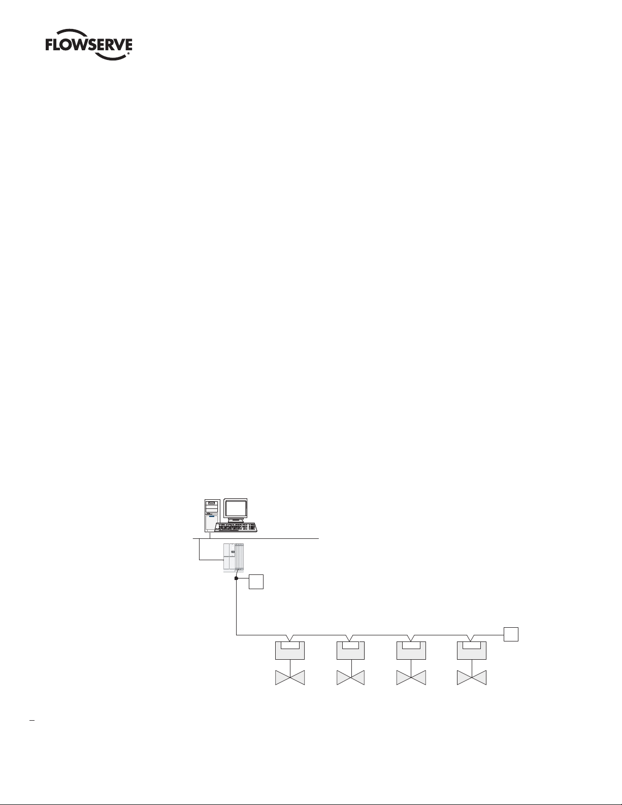
Figure 1.1 – Typical PROFIBUS DP Network with DCS or PLC as the Host System
Distributed Control
System (Host)
Control Highway
PROFIBUS DP-V1
Interface
T Terminator
Power for the fieldbus devices and cable shield
grounding are discussed in Sections 2.4 and 2.5.
PROFIBUS DP Network
Terminator
T
Actuator Actuator Actuator
PBPBPBPB
Actuator
8
Page 9
PB DPV1 / PA Field Unit Installation and Maintenance FCD LMENIM2336-03 – 12/12
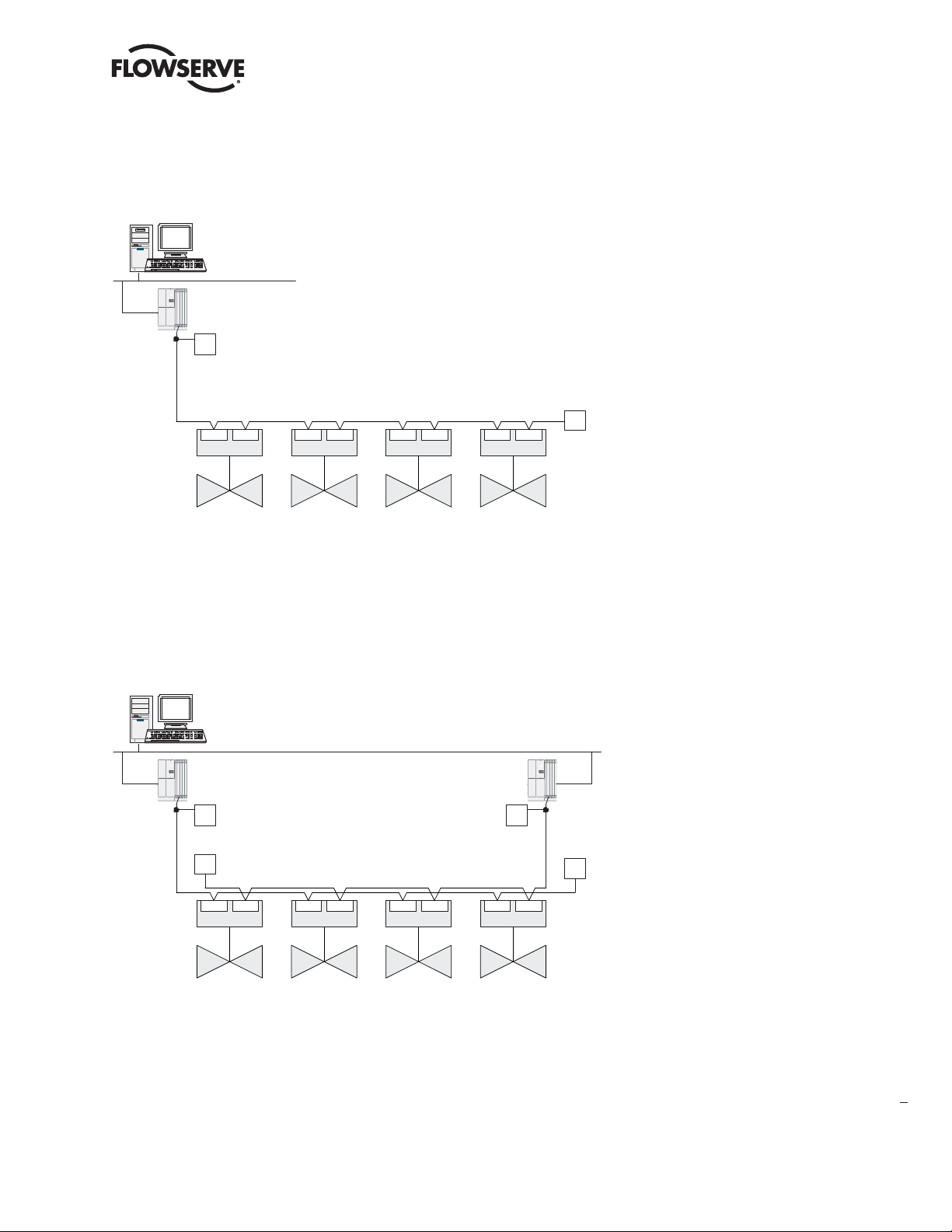
Figure 1.1a – Typical PROFIBUS DP Network with Redundancy Option (Single Master)
Distributed Control
System (Host)
Control Highway
PROFIBUS DP-V1
Interface
Terminator
T
PROFIBUS DP Network
PBDP-A PBDP-B
Actuator
PBDP-A PBDP-B
Actuator
PBDP-A PBDP-B
Actuator
PBDP-A PBDP-B
Actuator
Figure 1.1b – Typical PROFIBUS DP Network with Redundancy Option (Dual Master)
Distributed Control
System (Host)
Control Highway
PROFIBUS DP-V1
Interface-1
Terminator
T Terminator T
Terminator
T
PROFIBUS DP Network
PBDP-A PBDP-B
Actuator
PBDP-A PBDP-B
Actuator
PBDP-A PBDP-B
Actuator
PROFIBUS DP-V1
Interface-2
PBDP-A PBDP-B
Actuator
Terminator
T
Terminator
T
flowserve.com
9
Page 10
PB DPV1 / PA Field Unit Installation and Maintenance FCD LMENIM2336-03 – 12/12
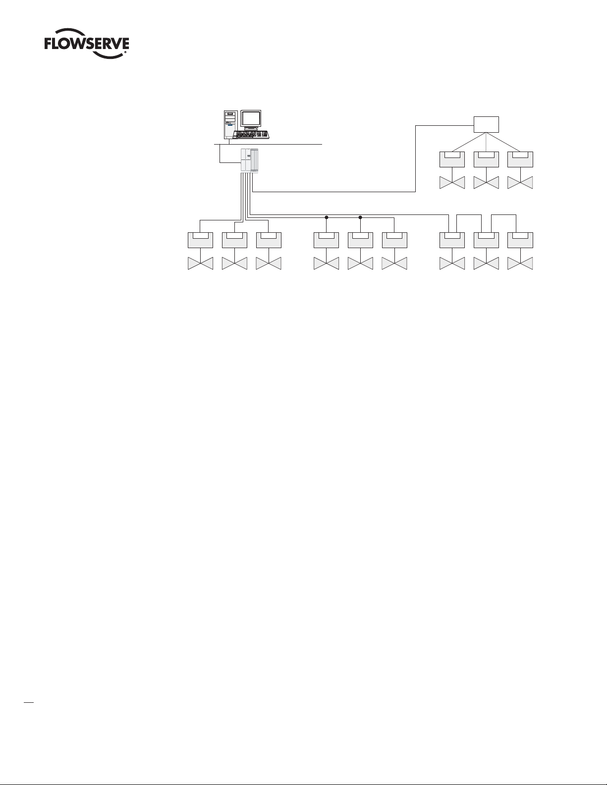
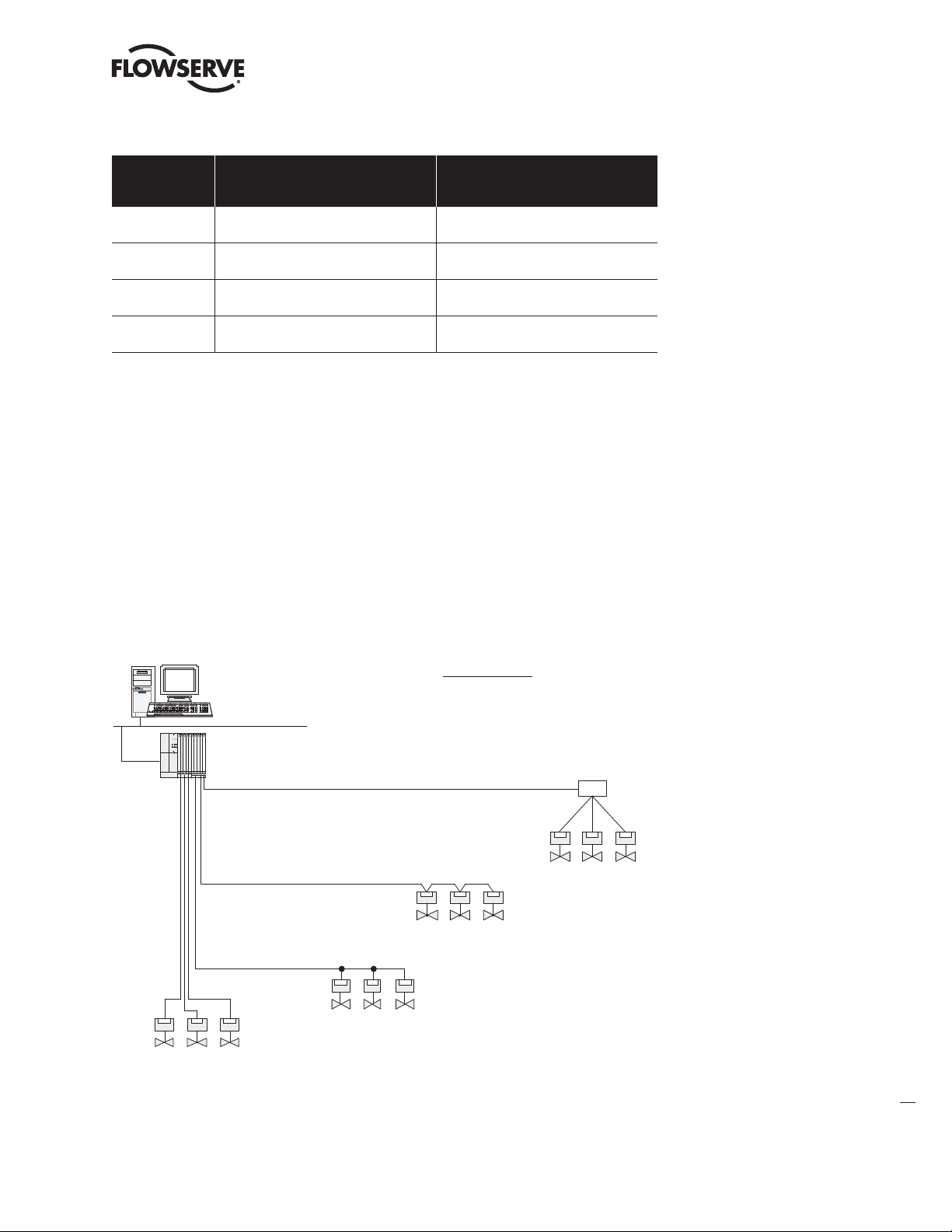
Figure 1.2 – Typical PROFIBUS PA Network with DCS or PLC as the Host System
Distributed Control
System (Host)
Control Highway
PROFIBUS PA
Interface
PA
ActuatorPAActuatorPAActuator
Point to Point Bus with spurs (or drops) Daisy Chain
Power for the fieldbus
devices and cable shield
grounding are discussed
in Sections 2.4 and 2.5.
PA
ActuatorPAActuatorPAActuator
1.5.1 General Network Specification
System Specifications:
• Communicates using the PROFIBUS DP or PROFIBUS PA protocol.
• PROFIBUS DP is V1 compliant.
• Employs high-speed communication.
• Complies with EN50170 fieldbus standard.
• PA Physical Layer with IEC1158-2.
• DP Physical Layer with RS-485.
Junction Box
PA
ActuatorPAActuatorPAActuator
Tree
PA
ActuatorPAActuatorPAActuator
10
Network Specification:
Several topologies are available including point-to-point, bus, tree, ring, or a combination of these.
Network features include:
• PROFIBUS DP high-speed communications up to 1.5 Mbit/sec.
• PROFIBUS PA communications are 31.25kbits/sec (segment coupler side).
• Master/slave communications.
• Multiple-master network systems.
• Redundant PROFIBUS DP with single or multiple-master communications.
MX/QX Field Unit Specification:
The field unit mounts inside the actuator, is software controlled, and has the following features:
• Input and Output Function Blocks.
• Device descriptions – describes device and parameters.
• Network communication – compliant with EN50170.
• Configurable by user – locally and via network.
Page 11

PB DPV1 / PA Field Unit Installation and Maintenance FCD LMENIM2336-03 – 12/12
PROFIBUS Master Specification
The PROFIBUS master is the network system host, and can be a PC, DCS, PLC, or some other
microprocessor-based device. The master is defined as the network node that has addressing, and
read/write privileges to slave devices that are assigned to it. A PROFIBUS network can have more
than one master, but one, and only one, token is active at a given time. The token provides the right
to access the transmission medium, as is passed between the active nodes (masters) with a token
telegram. The master host station acts as the bus arbiter, and does the following:
• Recognizes and adds new devices on the link.
• Removes non-responsive devices from the link.
• Distributes a priority-driven token for unscheduled cyclic transmissions between masters.
• Ensures cyclic data transferred on a periodic basis.
• Issues requests for process data from the field devices.
• Issues commands to the field devices.
High Speed Data Exchange – Startup Sequence
• Power ON / Reset – Power on / Reset of master or slave.
• Parameterization – download of parameters into the field device (selected during configuration by
the user).
• I/O Configuration – download of I/O configuration into the field device (selected during configuration by the user).
• Data Exchange – cyclic data exchange (I/O Data) and field device reports diagnostics.
NOTE: In the application profile definition, only Function Blocks may have cyclic parameters. Physical
Blocks and Transducer Blocks do not have cyclic parameters. PROFIBUS DP/V1 is part of the
requirement to access Acyclic parameters through the Function Block specification and is composed
of a slot number and an index number. Acyclic services are performed between two data exchange
cycles. A PROFIBUS Class 2 Master is required for acyclic data exchange (Function Blocks). An
Electronic Device Descriptor File is used in the configuration tool of the Master to gain access to the
Function Block parameters (refer to Chapter 3, Software).
Device Configuration Tool Requirements
Generally, the device configuration tool can be executed independently of the control system configuration tool. The general requirements are as follows:
• A PROFIBUS DP or PA network is inserted as an object of a control system project (or independent
project).
• Within that network, a device is logically attached along with object name, PROFIBUS DP/PA
address, and how many objects are to be attached.
• Editing this device will allow the user to select the type of device (actuator, sensor, etc.).
• The configuration tool will then display the extended parameters with initial values.
• These parameters may be uploaded from the device to display the actual values (if a network
connection is possible).
• New values can be entered and then downloaded to the device through the network connection.
• There will also be a method for monitoring the online parameter values.
11
flowserve.com
Page 12

PB DPV1 / PA Field Unit Installation and Maintenance FCD LMENIM2336-03 – 12/12
System Components
2
and Installation
2.1 Introduction
This section is an overview of the components used in the PROFIBUS system and their integration
with the MX/QX actuator. The MX/QX PB field unit is installed in the control compartment of the
actuator as shown in Figures 2.1a and 2.1b. The PROFIBUS network cable from the host control
station connects to the fieldbus unit at the actuator terminal block.
The Network Cabling section of this chapter is broken into two sections; PROFIBUS DP and
PROFIBUS PA.
Refer to Appendix A for detailed wiring connections.
12
Page 13
PB DPV1 / PA Field Unit Installation and Maintenance FCD LMENIM2336-03 – 12/12
2.2 Hardware
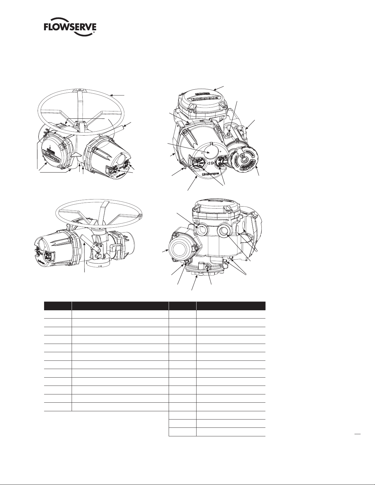
Figure 2.1a – MX-05 Actuator Figure 2.1b – QX-05 Actuator
10
1
3
11
13
5
12
2
9
OPTIONAL
15
1
9
7
4
9
3
14
8
6
3
3
11
10
9
12
4
8
7
2
2
5
6
Item Description Item
1 Handwheel 1 Handwheel
2 Declutch lever 2 Declutch lever (QX-05)
3 Oil fills (dotted arrow depicts fill on declutch side) 3 Oil fill
4 Controls compartment (field unit location) 4 Controls cover
5 LCD display 5 LCD display
6 Control knobs 6 Control knob
7 Ground lug 7 Ground lug
8 Thrust/torque base 8 Baseplate
9 Conduit entries 9 Conduit entry
10 Terminal compartment 10 Terminal compartment
11 Electric motor 11 Motor
12 Nameplate 12 Certification nameplate
13 Tag nameplate
14 Oil plug
15 Stem nut stops
13
flowserve.com
Page 14

PB DPV1 / PA Field Unit Installation and Maintenance FCD LMENIM2336-03 – 12/12
2.2.1 MX and QX Actuators
The MX and QX actuators are designed for operation of ON-OFF and modulating valve applications.
The MX is a multi-turn actuator, while the QX is a quarter-turn actuator.
Both the MX and QX include the following features:
• Non-intrusive setup.
• Separately sealed terminal compartment.
• Unique absolute encoder for valve position sensing (no battery required).
• 32-character LCD for indication and calibration.
• Enhanced electronic control, monitoring, and diagnostic capabilities with Built-In Self Test (BIST)
and LimiGard™ technology.
NOTE: Recommended storage procedures are detailed in the MX and QX Maintenance and Spare
Parts Manual LMENIM2314 and LMENIM3314 respectively. Failure to comply with recommended
procedures will void the warranty. For longer-term storage, contact Flowserve for procedure and
recommendations.
2.2.2 MX/QX PB Field Unit
The MX/QX PB field unit interface board is installed in the actuator controls compartment (Figure
2.1). The MX/QX PB DP version is shown in Figure 2.2, and the MX/QX PB PA version is shown in
Figure 2.3. Each unit permits the actuator to be controlled as a slave by one or more master host
stations over their respective PROFIBUS network. The MX/QX PB DP version supports two forms of
redundancy when two PB DP field unit boards are installed in a single actuator:
a. Flying redundancy provides slave hardware redundancy in the form of an active and standby PB
DP field unit installed in each actuator. This form is commonly utilized in applications where a single
master is present.
b. System redundancy provides for both slave hardware redundancy, in the form of an active and
standby PB field unit installed in each actuator, and cable redundancy in the form of dual masters
connected to the active and standby PB DP field units.
Figure 2.2 – MX/QX PB DP Field Unit
14
Note: Field unit board jumpers, JP1 and JP2, are set to “A” position on Primary board and “B” position on Redundant board.
Page 15

PB DPV1 / PA Field Unit Installation and Maintenance FCD LMENIM2336-03 – 12/12
Figure 2.3 – MX/QX PB PA Field Unit
The following commands and feedback information are transmitted through this unit:
• OPEN, CLOSE, and STOP commands.
• ESD (Emergency Shutdown) commands.
• Go-to-position commands.
• Redundancy switch-over commands (Profibus DP Redundancy option).
• Position feedback.
• Actuator status, alarm, and diagnostic messages.
• User analog input feedback.
• Discrete input feedback.
• Discrete output relays.
2.2.3 Network Host Station
The PROFIBUS master is considered to be the network host station, which is typically a DCS, PC,
PLC or other microprocessor-based PROFIBUS-compliant device. In a mono-master network, the
network host device is the only active network node. This is common in a standard Master-Slave
PROFIBUS network. In a multi-master network, there are two or more active nodes. This is managed
in a token ring, where the token, a uniquely structured message, circulates continuously among the
active network nodes. In the case of multiple Masters, only one Master has read/write privileges to
its Slaves (passive nodes) at any one time, and the control token is passed continuously in ascending
order to all other active network nodes.
2.2.3.1 Token Bus and Token Passing in a Multi-Master Network
During the bus initialization and startup, the bus access control creates the token ring by recognizing
the active network nodes in ascending order. The bus access control automatically determines the
addresses of all active nodes on the bus, and records them together with its own node address,
creating a List of Active Stations. The Lowest Station Address (LSA) begins with the active token,
allowing it to fetch and send data messages to its passive slaves (referred to as polling). At completion of its request frame (polling telegram), and acknowledgement or response frame returned from
the slave, the token is passed to the Next Station (NS) with a token telegram. The active node from
which the node was passed is called the Previous Station (PS). This continues until the token is being
passed from the Highest Station Address (HSA). At completion of the HSA polling telegram, the token
is passed to the LSA. The List of Active Stations is required during network operation to remove a
faulty active node, or to add a node, without disturbing data on the bus.
15
flowserve.com
Page 16

PB DPV1 / PA Field Unit Installation and Maintenance FCD LMENIM2336-03 – 12/12
2.2.3.2 Token Rotation Time
The time required for the rotation of the token to all active nodes is the token rotation time. The Time
Target Rotation (TTR) is adjustable, and is used to specify the maximum allowed time of one rotation.
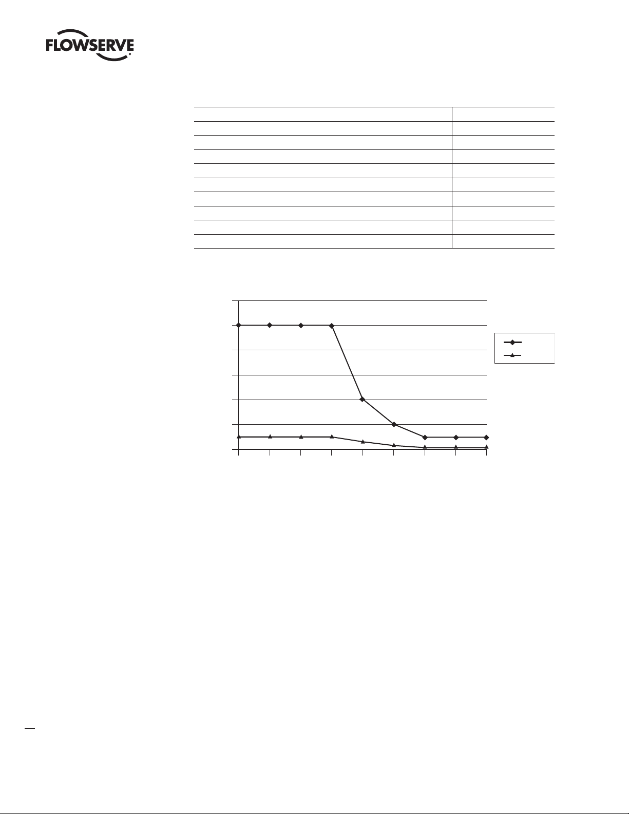
2.2.3.3 Bus Cycle Time
Based on the number of slaves attached to each master and the amount of data to be transferred, a
Bus Cycle Time is calculated by the master. This is the amount of time required for a master to poll all
slaves. This, along with the Token Rotation Time, makes PROFIBUS network access deterministic.
Figure 2.4 – Typical Cycle Time (Each Station with 2 Bytes I/O)
20.0
18.0
16.0
14.0
12.0
10.0
8.0
Cycle Time (ms)
6.0
4.0
2.0
0.0
2.0
0.9
4.6
1.5 MBaud
500 kBaud
2.0
51
Number of Slaves
7.7
3.3
10 20
14.1
8.8
6.1
30
16
2.2.4 Network Cabling for PROFIBIS DP
Network cabling should be in accordance with PROFIBUS Decentralized Periphery (DP) guidelines.
To achieve immunity to electromagnetic interference, ensuring high data integrity, certain cables and
guidelines are recommended. Additionally, the following items should be taken into account when
planning the network:
• Transmission rate – Within a network, only one transmission rate can be used; the MX/QX PB DP
works at baud rates up to 1.5 Mbps.
• The level of Master and Slave redundancy, if any.
• The required number of nodes.
• The type of network components needed – terminals, connectors, connecting cables, termination.
• The type of cable to be used and its characteristics.
• The number of segments and/or repeaters.
• The overall span of the network – adding repeaters and long cable lengths can increase transmis-
sion time.
• Cable termination – active termination resistors are required at the ends of all segments.
In general, the following rules apply for PROFIBUS networks:
• The higher the baud rate, the shorter the distance allowed between nodes.
• The higher the baud rate, the shorter the maximum distance of a segment.
• The higher the baud rate, the shorter the maximum distance of an entire network.
Page 17

PB DPV1 / PA Field Unit Installation and Maintenance FCD LMENIM2336-03 – 12/12
These distance rules (or limitations) are based on the physical characteristics of the RS-485 topology
and are not a limitation of the PROFIBUS protocol. If the distance required between two stations or
the total network distance is greater than allowed by the PROFIBUS specifications for copper cable, a
conversion to fiber-optic cable may be required. Figure 2.5 shows the baud rate versus copper cable
distance using PROFIBUS.
Table 2.1 provides the guidelines for maximum segment length versus baud rate.
Table 2.1 – Maximum Segment Length
Baud Rate 9600 to 187.5K 500K 1.5M
Maximum Segment Length (meters) 1,000 400 200
Table 2.2 provides the guidelines for maximum network length versus baud rate (assuming the use of
up to 9 repeaters).
Table 2.2 – Total Network Length (with up to nine repeaters)
Baud Rate 9600 to 187.5K 500K 1.5M
Total Network Length (meters) 10,000 4,000 2,000
NOTE: The maximum lengths are estimates and depend on the condition of the actual cable.
Tables 2.3 and 2.4 detail the various types of cable which can be used for network cabling. For
additional guidelines, see the following publications:
• PROFIBUS Networks SIMATIC NET 6GK1970-5CA20-0AA1.
• PROFIBUS Technical Guideline for PROFIBUS-DP/FMS, Version 1.0, September 1998; PROFIBUS
Guideline, Order No. 2.112.
There are different types of electrical data transfer cables:
• Standard bus cable.
• Standard bus cable with halogen-free sheath (type FRNC).
• Cable with PE sheath for use in the food and drug manufacturing industries.
• Direct buried cable with additional protective sheath for buried service.
• Trailing cable – This is a special cable type which is used where parts of the machine move
occasionally or continuously.
• Festooned cable – Comparable to a trailing cable, but has an additional strain relief element.
NOTE: Cable must meet the requirements as listed in table 2.3 to ensure reliable network
communications.
Table 2.3 – Recommended PROFIBUS DP Cable Parameters
Characteristic impedence at 3-20 MHz (ohms) 135-165
Operating capacitance (pF/m) < 30
Loop resistance (ohms/km) ≤ 110
Core diameter (mm) > 0.64
2
Core cross-section (mm
) > 0.34
17
flowserve.com
Page 18
PB DPV1 / PA Field Unit Installation and Maintenance FCD LMENIM2336-03 – 12/12
Table 2.4 – Recommended PROFIBUS DP Cable Types
FC Standard Cable (Siemens AG) 6XV1 830-0EH10
FRNC Cable (Siemens AG) 6XV1 830-0CH10
FC Food Cable (Siemens AG) 6XV1 830-0GH10
FC Ground Cable (Siemens AG) 6XV1 830-3FH10
FC Trailing Cable (Siemens AG) 6XV1 830-3EH10
Festoon Cable (Siemens AG) 6XV1 830-3GH10
PROFIBUS Data Cable (Belden Wire and Cable) 3079A/3076F
PROFIBUS DP Cable (Moeller GmbH) ZB4-900-KB1
PROFIBUS DP Cable (Kerpenwerk GmbH) 7422/7436
PROFIBUS DP Cable (ABB Automation GmbH) NDC110-NO
Figure 2.5 – Copper PROFIBUS Distance vs. Baud Rate Chart
12,000
10,000
8,000
Network
Segment
6,000
4,000
Distance (m)
2,000
1,000 1,000 1,000
0
9.6
19.2
93.75
1,000
187.5
Baud Rate (kBaud)
400
500
200
1,500 3,000
100
1,000 1,000
100
12,000
6,000
100
There are several topologies available for both redundant and non-redundant PROFIBUS networks:
• Point-to-point – A single cable from master to slave.
• Daisy chain – A single cable daisy chained in and out of each field unit device. End of segment
devices only have one incoming cable.
• Tree – Cables and electronic devices (such as repeaters or link modules) are used to branch out
from different points.
• Ring – Often implemented with fiber-optic cable which forms a circle or ring when used with
Optical Link Modules. This topology yields redundancy so that any single component fault or cable
break does not affect the network (except for the component).
• Combination of the above.
NOTE: Bus with Spurs, also referred to as stub lines, are not recommended by PROFIBUS as they can
create parallel resistance and cause disturbances and reflections on the main trunk or bus line.
18
Page 19
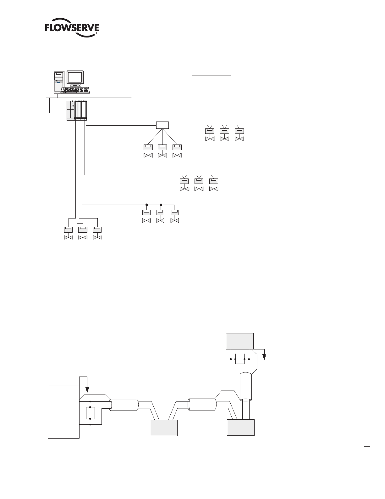
Figure 2.6 – Cable Topologies
PB DPV1 / PA Field Unit Installation and Maintenance FCD LMENIM2336-03 – 12/12
PROFIBUS
Interface
Point-to-point
Distributed Control
System (Host)
Network
Schematic topology: Details such
as terminators and power supplies
not shown
Repeater
Daisy Chain
Tree
Daisy Chain
Bus with spurs
(or drops)
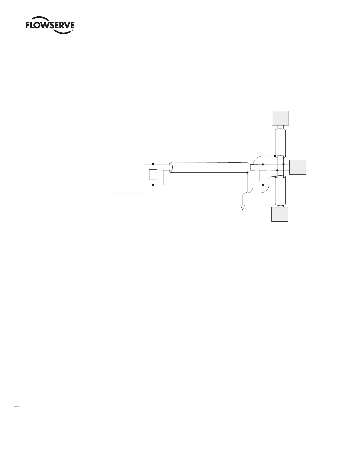
2.2.4.1 Cable Shielding and Grounding for PROFIBUS DP
For best performance, PROFIBUS DP cables should be shielded. Per PROFIBUS Technical Guidelines,
the cable shield should be connected at the beginning and end of the segment. Alternatively, a 10-12
AWG ground wire may be run to each MX/QX.
In Figure 2.7, the grounding point is shown at the junction of the field devices and at each field device.
Figure 2.7 – Use of Shielded Cable in PROFIBUS DP
Field
Device
T
PROFIBUS
Interface
T
Field
Device
Field
Device
19
flowserve.com
Page 20

PB DPV1 / PA Field Unit Installation and Maintenance FCD LMENIM2336-03 – 12/12
2.2.5 Network Cabling for PROFIBUS PA
Network cabling should be in accordance with PROFIBUS Process Automation (PA) guidelines using
twisted-pair shielded cable. The data line is normally also used to supply power to the field devices.
PROFIBUS PA is a combination of the PROFIBUS-DP V1 protocol and the IEC 61158-2 transmission
technique.
The following items should be taken into account when planning the network:
• Transmission rate – Within a network, only one transmission rate can be used; typical restrictions
of PA are 31.25kbits/sec.
• The required number of nodes.
• The type of network components needed – Terminals, connectors, connecting cables, termination.
• The type of cable to be used and its characteristics.
• The number of segments and/or repeaters.
• The overall span of the network – Adding repeaters and long cable lengths can increase transmis-
sion time.
• Cable termination – Active termination resistors are required at the ends of all segments.
Tables 2.5 and 2.6 detail the recommended cable parameters and various types of cable that can be
used for network cabling. For additional guidelines, see the following publications:
• PROFIBUS Networks SIMATIC NET 6GK1970-5CA20-0AA1
• Technical Guideline – PROFIBUS PA User and Installation Guideline Version 2.2 February 2003,
PROFIBUS Guideline Order No. 2.092
Table 2.5 – Recommended PROFIBUS PA Cable Parameters (Type A – shielded twisted-pair)
Characteristic impedence 100 ohms ±20%
Maximum capacitance 2 nF/km
Loop resistance 44 ohms/km
2
Conductor cross-sectional area 0.8 mm
Maximum length of network (including spurs) 1900 m
(AWG 18)
Table 2.6 – Recommended PROFIBUS PA Cable Types
PA, Ex and Non-Ex
(ABB Automation Products GmbH)
PA, Ex and Non-Ex
(ABB Automation Products GmbH)
PROFIBUS FC Process Cable (Siemens AG) 6XV1 830-5.H10
PROFIBUS Data Cable (Beldon Wire & Cable) 3079A & 3076F
UNITRONICS Bus PA (Lapp Kabel GmbH) 2170 235 1x2x1.0
NPC080-NO
NPC150-NO
20
Page 21
PB DPV1 / PA Field Unit Installation and Maintenance FCD LMENIM2336-03 – 12/12
Table 2.7 – Recommended Lengths of PROFIBUS PA Spurs (Stubs)
Number of Spur
Cables
19 to 24 30 30
15 to 18 30 60
13 to 14 30 90
1 to 12 30 120
Length of Spur Cable
Intrinsically Safe (m)
Length of Spur Cable
Non-Intrinsically Safe (m)
NOTE: The maximum lengths are estimates and depend on the condition of the actual cable.
There are several topologies for PROFIBUS networks:
• Daisy Chain – A single cable daisy chained in and out of each device. End devices only have one
cable.
• Tree – Cables and electronic devices (such as repeaters or link modules) are used to branch out
from different points.
• Star – Similar to a Tree configuration but the cables all originate from one centralized point that is
comprised of electronic devices (such as repeaters or link modules).
• Combination of the above.
Figure 2.8 – PROFIBUS PA Cable Topologies
Distributed Control
System (Host)
Control Highway
PROFIBUS
Interface
Point-to-point
Schematic topology: Details such
as terminators and power supplies
not shown
Junction
Box
Tree
Daisy Chain
Bus with spurs
(or drops)
flowserve.com
21
Page 22
PB DPV1 / PA Field Unit Installation and Maintenance FCD LMENIM2336-03 – 12/12
2.2.5.1 Cable Shielding and Grounding for PROFIBUS PA
For best performance, PROFIBUS PA cables must be shielded. When using shielded cable, connect
each cable shield to the trunk shield, and connect the overall shield to the PROFIBUS power supply
ground.
In Figure 2.9, the grounding point is shown at a connection point of power supply return.
Figure 2.9 – Use of Shielded Cable in PROFIBUS PA
Field
Device
Shielded Wire Pair
Field
PROFIBUS
Interface
T
T
Device
Connect Shield
to Ground at one
place only
Field
Device
2.2.5.2 PROFIBUS PA Power Supply
The MX/QX PB/PA board requires a nominal 24 VDC (9-32 VDC) on the PA bus to power the MX/QX
PB/PA board and make the actuator visible on the network. The required power supply is typically
connected to a segment coupler to the bus, usually located at the host end of the cable. Validate the
requirements of the segment coupler to determine actual power and voltage.
NOTE: If the actuator does not have three-phase power and the network is active, the MX/QX PB/PA
board will report this condition to the host.
22
Page 23

PB DPV1 / PA Field Unit Installation and Maintenance FCD LMENIM2336-03 – 12/12
Figure 2.10 shows a typical PROFIBUS PA power supply arrangement.
Figure 2.10 – PROFIBUS PA Power Supply
Fieldbus
Power
Supply
+
-
Field
Device
PROFIBUS PA
Interface
Shielded Wire Pair
T
NOTE: Bus power supply may be integrated
with the PROFIBUS PA bus interface.
T
Field
Device
Field
Device
2.3 Other Network Components
In addition to the network cables, the following components may be used in the PROFIBUS network.
Each network is designed based on its application and therefore may not require all of these
components.
• Bus Terminal Blocks/Junction Box – Provides multiple connections to the bus (network).
• Active Bus Terminal – Provides active termination so that other stations may be powered down for
service without affecting the network.
• Connectors – Enable connections to junction boxes, terminators or other connectors. Useful in
installations where devices will be periodically disconnected or when a device is only going to be
temporarily disconnected. Some PROFIBUS connectors also include termination resistors for line
termination.
• Couplers – Provide one or several connection points to a network segment.
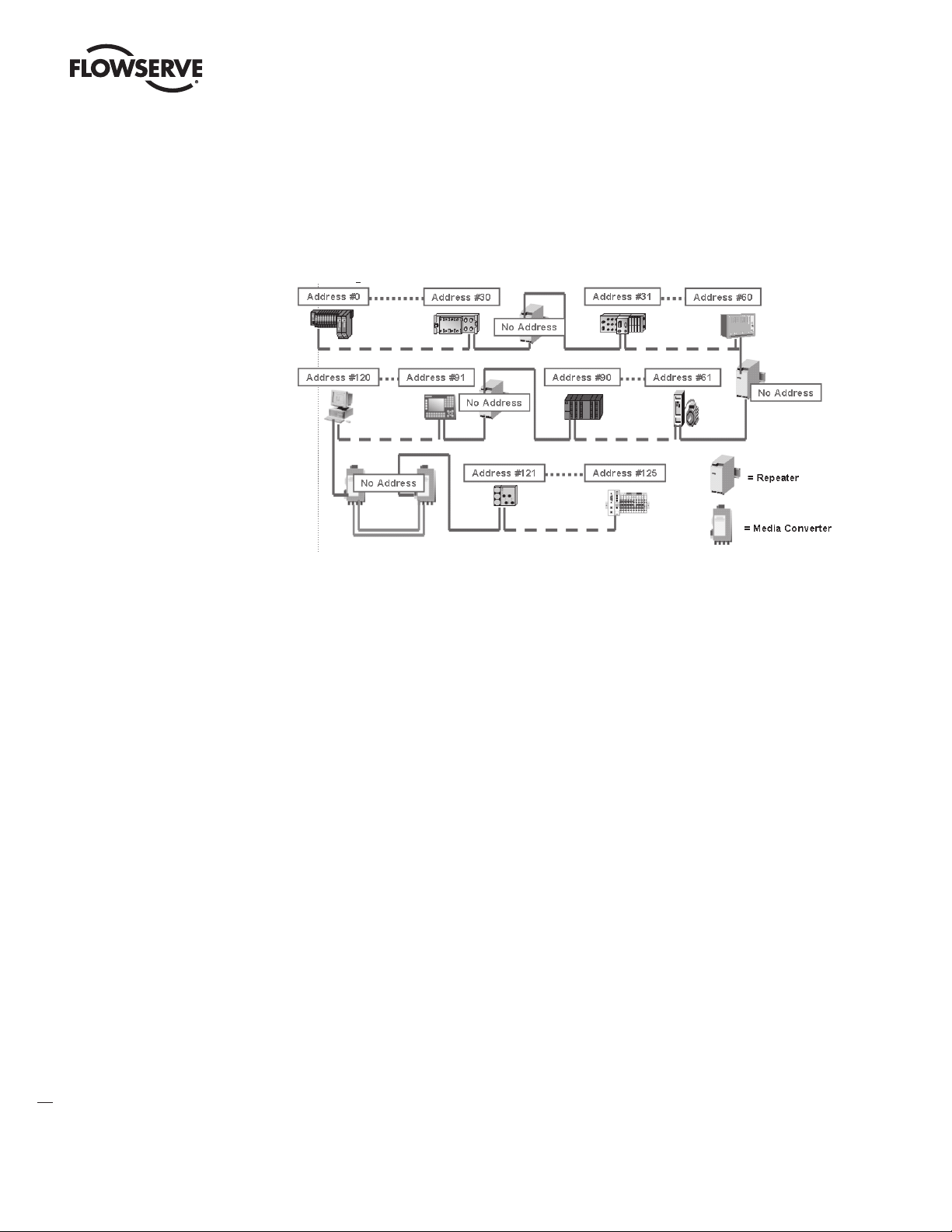
• Repeaters – The PROFIBUS Physical Layer (RS-485) dictates that no more than 32 nodes can exist
in a shielded twisted-pair (copper) segment. A node is defined as any station, active or passive,
that is connected to the network. Media converters (copper to fiber-optic, fiber-optic to copper) and
repeaters do not have PROFIBUS addresses and, therefore, are not included in the 126 possible
addressable nodes.
RS-485 repeaters may be used to extend the recommended distance of a segment and “reform”
the signal to full voltage levels. Repeaters are included in the total number of allowable nodes per
segment; therefore, a segment that begins with a repeater and ends with a repeater may have 30
nodes between them. The maximum number of repeaters allowed in a PROFIBUS network is nine.
(Refer to Figure 2.11.)
• Terminators – Used at each end of a PROFIBUS segment to prevent signal reflections.
• Power Supplies – Different types of power supplies can be used in a PROFIBUS network:
• Non-intrinsically safe power supply.
• Standard linear or switching power supply used with a power conditioner.
• Intrinsically safe power supply (9-32 VDC; nominal 24 VDC for PA).
23
flowserve.com
Page 24
PB DPV1 / PA Field Unit Installation and Maintenance FCD LMENIM2336-03 – 12/12
For cable connecting information on these components, refer to the following:
• Installation Guidelines for PROFIBUS – FMS/DP Version 1.0, PROFIBUS International Order No.
2.112.
• Technical Guideline: PROFIBUS PA User & Installation Guideline, Version 2.2, February 2003.
Figure 2.11 – PROFIBUS DP Segments
24
2.4 Site and Network Cable Preparation
2.4.1 Site Preparation
Prepare the installation site and associated equipment for operation of the MX/QX PB-controlled
actuators as follows:
1. Prepare a detailed site plan consisting of the following:
• Actuator locations and tag numbers.
• Junction boxes and terminal strip locations and tag numbers.
• Terminators and power supplies/conditioners, and repeaters.
2. Provide free access to the MX/QX control panel and terminal block for setup, configuration, and
troubleshooting.
3. Prepare the cable and label all wires. See Section 2.4.2.
4. Install power and control wires in separate conduits.
5. Install and verify earth grounds. The cable shields should be tied together. Ground the bus shield
at the end of each segment. The MX/QX PB unit should not connect either conductor of the cable
to ground at any point in the network. Refer to Sections 2.2.4.1 and 2.2.5.1.
NOTE: An effective local earth ground is defined as a low impedance (less than 5 ohms) path to
either:
• A ground electrode placed in the close vicinity of the actuator, free of any ground loop currents OR
Page 25

PB DPV1 / PA Field Unit Installation and Maintenance FCD LMENIM2336-03 – 12/12
Figure 2.12(a) – PROFIBUS DP Cable Connections to Terminal Blocks
Figure 2.12(b) – PROFIBUS DP Cable Connections (Redundancy option with single master) to Terminal Blocks
• A safety ground, free of ground loop currents, running from the actuator back to the system
ground electrode. If the signal wiring is run on aerial cable where it may be exposed to
high-energy electrostatic discharge (such as lightning), a low impedance path to ground which
is capable of high current must be provided a short distance from the actuator as described
above OR
• A power distribution grid identifying the impact of power isolation to a particular actuator or
group of actuators.
2.4.2 Network Cable Preparation
Care must be taken during cable preparation:
• When stripping the insulation, use wire strippers that do not nick the wire.
• Use crimp ferrules to prevent stranded wires from getting loose and shorting to other wires.
• Use vibration-resistant wiring terminals that hold the ferrule securely.
2.4.2.1 Network Cable Connection to the MX/QX PB Unit
The field device is connected to the PROFIBUS network through the MX/QX terminal block.
The PROFIBUS DP network cable is connected to the terminal block as shown in Figure 2.12.
NOTE: The MX/QX PB DP device is sensitive to polarity. Cable polarity should be maintained through
all connection points.
The PROFIBUS PA network cable is connected to the terminal block as shown in Figure 2.13.
NOTE: The MX/QX PB PA device is equipped with automatic polarity identification. It is not polarity
sensitive.
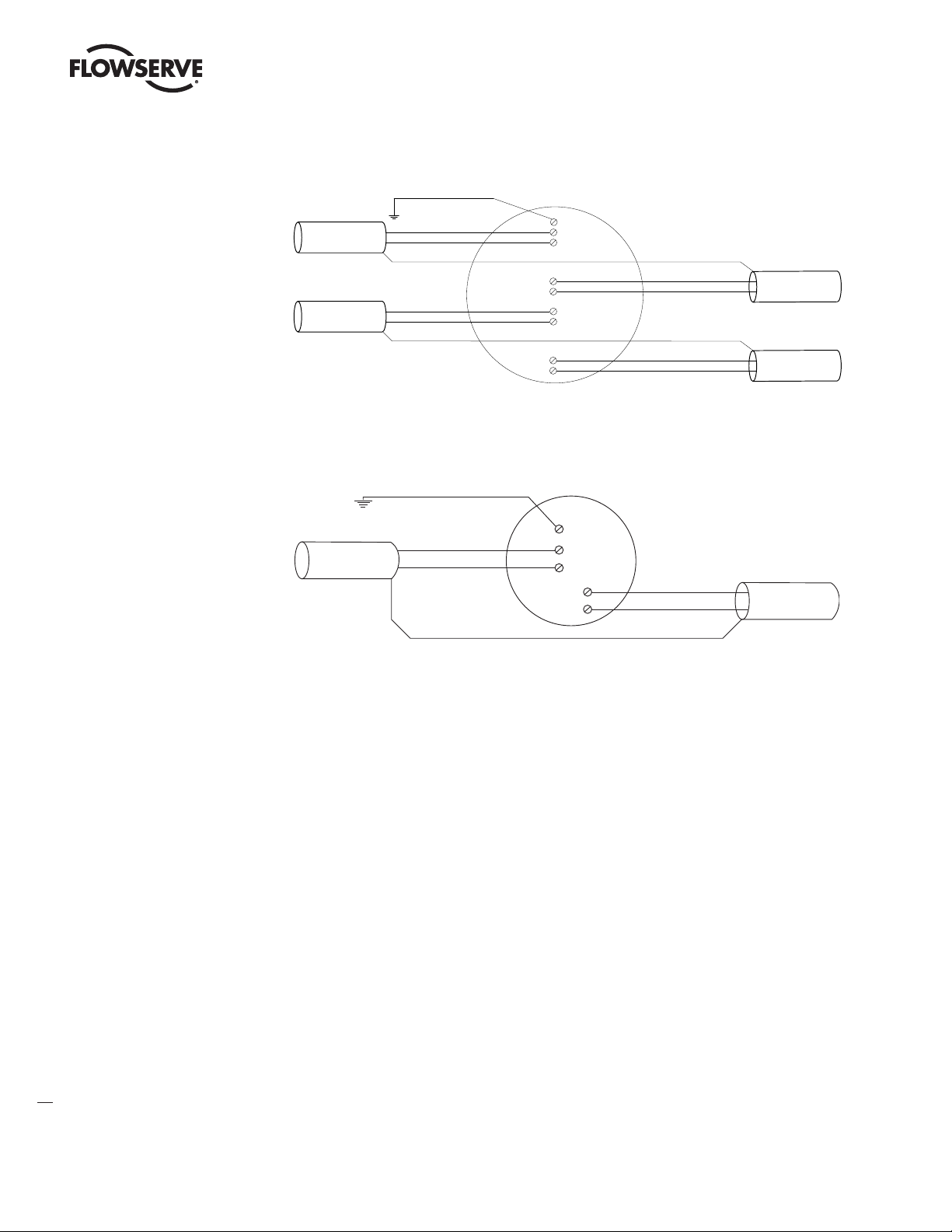
Figure 2.12a – PROFIBUS DP Cable Connections to Terminal Blocks
Earth ground
Network data PBDP-A (-)
Network data PBDP-A (+)
3
14
IN
13
4
OUT
5
Network data PBDP-A (-)
Network data PBDP-A (+)
Figure 2.12b – PROFIBUS DP Cable Connections (Redundancy option with single master)
to Terminal Blocks
Earth ground
Network data PBDP-A (-)
Network data PBDP-A (+)
3
14
IN
13
Note: External jum per connection requi red between
15
16
a) Termi nals 14 & 15
b) Termi nals 13 & 16
4
OUT
5
Network data PBDP-A (-)
Network data PBDP-A (+)
25
flowserve.com
Page 26
PB DPV1 / PA Field Unit Installation and Maintenance FCD LMENIM2336-03 – 12/12
Figure 2.12(c) – PROFIBUS DP Cable Con nections (Redundancy option with dual master) to Terminal Blocks
Figure 2.12c – PROFIBUS DP Cable Connections (Redundancy option with dual master)
to Terminal Blocks
Earth ground
OUT
3
14
IN
13
4
OUT
5
1
2
15
IN
16
Network data PBDP -A(-)
Network data PBDP -A(+)
Network data PBDP -B(-)
Network data PBDP -B(+)
Figure 2.13 – PROFIBUS PA Cable Connections to Terminal Blocks
Earth ground
Network data PBPA1(-)
Network data PBPA1(+)
3
4
5
14
13
Network data PBPA1(-)
Network data PBPA1(+)
Network data PBDP -A(-)
Network data PBDP -A(+)
Network data PBDP -B(-)
Network data PBDP -B(+)
26
Page 27

PB DPV1 / PA Field Unit Installation and Maintenance FCD LMENIM2336-03 – 12/12
• Shielded twisted-pair cables in compliance to PROFIBUS standards must be used.
• Shields are connected to earth ground.
PB/DP connects at the ends of each segment.
PB/PA connects at only a single point in the segment.
• Clean earth-ground connection (less than 5 ohms) provides noise protection and a clear, safe path
for surge currents.
Prepare the network cable for connection to the MX/QX terminals as follows:
CAUTION: Strip stranded conductors carefully, do not damage the strands. This will weaken
a
the conductor and can cause the conductor to break. This type of damage may not be
apparent and failure can occur without warning.
1. Remove two to three inches (5 to 8 cm) of the outer jacket of the cable as shown in Figure 2.14.
Do not cut or nick the shield or the insulated conductors.
Figure 2.14 – Removing Outer Plastic Jacket
NOTE: Excess cable should be cut and removed, not coiled or looped, to prevent noise induction into
the network.
2. Separate the cable parts. Unbraid the shield and peel back the shield to the same point where the
outer jacket was removed as shown in Figure 2.15.
Figure 2.15 – Separating Cable Parts
27
flowserve.com
Page 28

PB DPV1 / PA Field Unit Installation and Maintenance FCD LMENIM2336-03 – 12/12
3. Cut away the foil shield. Strip the insulation from the conductors approximately 0.4 inch (1 cm)
as shown in Figure 2.16.
Figure 2.16 – Stripping Conductors
4. Apply heat-shrink tubing to insulate the braided shield and to provide stress relief to the cable as
shown in Figure 2.17.
Figure 2.17 – Applying Heat-Shrink Tubing
CAUTION: Do not melt the insulation during the application of heat-shrink tubing.
a
5. Install ring tongue connectors as shown in Figure 2.18.
NOTE: Flowserve recommends the use of Thomas and Betts #RZ22-6 for optimum results.
28
Page 29

PB DPV1 / PA Field Unit Installation and Maintenance FCD LMENIM2336-03 – 12/12
Figure 2.18 – Ring Tongue Connectors
6. Connect the network cables to the MX/QX terminal block as shown in Figure 2.19.
Table 2.8 – Details of Terminal Block Cable Assignments
Terminal Block
Number
1 PBDP-B (-) Out N/A
2 PBDP-B (+) Out N/A
3 Surge/Ground Surge/Ground
4 PBDP-A (-) Out PBPA1 (-)
5 PBDP-A (+) Out PBPA1 (+)
13 PBDP-A (+) In PBPA1 (+)
14 PBDP-A (-) In PBPA1 (-)
15 PBDP-B (-) In N/A
16 PBDP-B (+) In N/A
DP Connection PA Connection
NOTE: Terminal 3 must be connected to earth ground in each actuator for field unit surge
suppression.
NOTE: Ground each segment of the cabling at each field device unit. See Section 2.2.4.1 and
2.2.5.1. Verify the actuator is properly grounded.
7. Connect the cable shields to each other inside the unit. Do not connect them to the unit in any
way. The network shield should be grounded at the end of each segment. For surge suppression,
Terminal 3 must be tied to earth ground in both DP and PA applications.
29
flowserve.com
Page 30

PB DPV1 / PA Field Unit Installation and Maintenance FCD LMENIM2336-03 – 12/12
Figure 2.19 – Connecting Network Cable to the MX/QX Terminal Block
2.4.2.2 Network Cable Connection to the Host System
For instructions on connecting to the host system, see the applicable host system/station. There are
several topologies for the network detailed in Installation Guideline for PROFIBUS-DP/FMS, Version
1.0, September 1998 and PROFIBUS PA User and Installation Guideline, Version 2.2, February 2003.
2.4.3 MX/QX PB Device Installation
The MX/QX PB board is located in the electrical housing of the actuator unit. The PB board has four
standoffs and mounts on top of the main processor board as shown in Figure 2.20. An optional
redundant PB DP board or Input/Output (I/O) board may also be present. The PB and I/O boards
may be inserted in any order on top of the main processor board. For detailed installation instructions, refer to the MX or QX Maintenance and Spare Parts Manuals, LMENIM2314 or LMENIM3311,
respectively.
Figure 2.20a – MX/QX PB DP Primary Figure 2.20b – MX/QX PB DP Primary and
Board Mounted to MX/QX Main Board Redundant Boards Mounted to MX/QX
Main Board
30
Note: Field unit board jumpers, JP1 and JP2, are set to “A” position on Primary board
and “B” position on Redundant board.
Page 31

PB DPV1 / PA Field Unit Installation and Maintenance FCD LMENIM2336-03 – 12/12
Figure 2.21 – PROFIBUS DP Setup Sequence
2.5 MX/QX PB Device Setup
The MX/QX PB option enables the actuator to be controlled by a PROFIBUS communications signal.
If the option has been purchased, it is automatically enabled.
NOTE: If the PB option has not been purchased, the screens for changing PB will not be available. To
add the option, please consult Flowserve Limitorque service at (434) 528-4400.
Figure 2.21 – MX/QX PB DP Setup Sequence
YES
NO
CHA NGE
PB/DP ?
PB DP- A STA TUS
(ON) - OK ?
NO
YES
ES D AC TION
(IGNORE )-OK?
(CLOSE )
NO
(OPEN )
(STOP)
(POSITION )
*
ES D MOVE TO
(X XX%) - OK ?
(0-100% )
Figure 2.21 illustrates the setup sequence for the MX/QX PB DP field unit. For proper operation, either
Position Mode or Open/Close Mode must be selected.
Follow these steps to enter and configure the setup mode:
1. Proceed through the Setup to the CHANGE PBDP? display.
2. Select YES to proceed to the PBDP-A STATUS (ON)-OK? display. PBDP-A Status enables the
user to change from the default condition to turn on and off the digital control capability of the
actuator.
3. Select YES to proceed to the PBDP-B STATUS (ON)-OK? display. PBDP-B Status enables the user
to change from the default condition to turn on and off the redundant digital control capability of
the actuator, if installed.
YES
NO
PB DP-B STATU S
(ON) -OK ?
YES
NO
COMM LOSS
AC TION
(NONE) –OK ?
(CLO SE)
(OP EN)
(S TOP)
(P OSITION )
YES
NO
YES
RE DUND ANT
MAS TER
(Y ES) - OK ?
*
MOVE TO
(X XX% ) - O K?
(0-100% )
NO
NO
YES
YES
MONITOR
STA NDB Y PB
(ON) -OK ?
COMM LOSS
DE LAY
60 SE CS-O K?
(0-4095)
YES
PB ADD RES S 1
OK?
(0-1 25)
NO
Unit incremen ts
YES YES
OPE N/CLOSE
MODE - OK?
NO
NO
POS ITION
MODE - OK?
NO
YES
YES
AN ALOG S CALE
0-10 0-OK?
(0-255)
(0-4095)
CHA NGE PROP/
DE AD B AND?
NO
YES
NO
YES
(1%-100 %)
1% Incr ements
PR OP BA ND
(15% ) - OK?
NO
If P OSITION is cho sen, as action,
*
this menu will appear.
YES
DE ADB AN D
(2% ) - OK?
(1%-50% )
1% Incr ements
YES
NO
4. Select YES to proceed to the REDUNDANT MASTER (YES)-OK? display. Selecting REDUNDANT
MASTER will allow for System Redundancy with two independent connections to Profibus
masters. REDUNDANT MASTER must be set to NO for Flying Redundancy (single Profibus
master connection).
5. If YES is selected, MONITOR STANDBY PB (ON)-OK? is displayed.
6. To allow the standby Profibus master to monitor the health of the actuator’s standby PB DP
board, select YES.
31
flowserve.com
Page 32

PB DPV1 / PA Field Unit Installation and Maintenance FCD LMENIM2336-03 – 12/12
7. The unit will display PB ADDRESS 1–OK? If OK, select YES. If NO, select different address
(1-125).
8. Select YES to proceed to the ANALOG SCALE display.
9. From ANALOG SCALE, if the default value of 0-100 is OK, select YES. If not, select NO.
10. If YES is selected, ESD ACTION (IGNORE) – OK? is displayed.
11. For ignoring ESD ACTION, select YES. For setting ESD ACTION, select NO. If POSITION is chosen
as action, ESD MOVE TO (XXX%)-OK? is displayed. Select NO to set desired position.
12. If YES is selected, COMM LOSS ACTION (NONE) – OK? is displayed.
13. For no COMM LOSS ACTION, select YES. For setting COMM LOSS ACTION, select NO. If
POSITION is chosen, as action, MOVE TO XXX% OPEN is displayed. Select NO to set desired
position.
14. If YES is selected, COMM LOSS DELAY (60 SEC) – OK? is displayed.
15. For a 60-second delay, select YES. Otherwise, select NO until the required value is displayed.
16. If YES is selected, OPEN/CLOSE MODE-OK? is displayed.
NO
CHANGE
PB/PA?
YES
ESD ACTION
(IGNORE)-OK?
(CLOSE)
(OPEN)
(STOP)
(POSITION)
STATUS
(ON)-OK?
NO
17. For OPEN/CLOSE MODE, select YES. For POSITION MODE, select NO. In position mode, the host
device can set the valve position to any desired value; in OPEN/CLOSE MODE the host can only
fully open or fully close the valve. The user must locally configure one of these two modes.
18. Proceed to configure the proportional band and deadband as discussed in sections 2.5.1 and
2.5.2, respectively.
Figure 2.22 – MX/QX PB PA Setup Sequence
YES
PB ADDRESS
NO(OFF)
YES
XXX% OPEN
(0-100%)
(1)-OK?
MOVE TO
YES
ANALOG SCALE
(1-125)
NO
Unit Increments
COMM LOSS ACTION
YES
(POSITION)
NO
0-100-OK?
(NONE)-OK?
(CLOSE)
(OPEN)
(STOP)
YES
NO
YES YES
COMM LOSS DELAY
(60 SEC)-OK?
MOVE TO
XXX% OPEN
YES
NO
(0-4095)
NO
**
(0-100%)
YES
OPEN/CLOSE
MODE-OK?
NO
NO
POSITION
MODE-OK?
CHANGE PROP/
DEADBAND?
YESYES YES
PROP BAND
(15%)-OK?
(1%-100%)
NO NO
1% Increments
DEADBAND
(2%)-OK?
(1%-50%)
1% Increments
If POSITION is chosen, as action,
*
this menu will appear.
YES
NO
32
Figure 2.22 illustrates the setup sequence for the MX/QX PB PA. For proper operation, either Position
Mode or Open/Close Mode must be selected.
Follow these steps to enter and configure the setup mode:
Page 33

PB DPV1 / PA Field Unit Installation and Maintenance FCD LMENIM2336-03 – 12/12
1. Proceed through the Setup to the CHANGE PB/PA? display.
2. Select YES to proceed to the STATUS (ON)-OK? display. PB Status enables the user to change
from the default condition to turn on and off the digital control capability of the actuator.
3. The unit will display PB ADDRESS 1–OK? If OK, select YES. If NO, select different address
(1-125).
4. Select YES to proceed to the ANALOG SCALE display.
5. From ANALOG SCALE, if the default value of 0-100 is OK, select YES. If not, select NO.
6. If YES is selected, ESD ACTION (IGNORE) – OK? is displayed.
7. For ignoring ESD ACTION, select YES. For setting ESD ACTION, select NO. If POSITION is
chosen as action, ESD MOVE TO XXX% OPEN is displayed. Select NO to set desired position.
8. If YES is selected, COMM LOSS ACTION (NONE) – OK? is displayed.
9. For no COMM LOSS ACTION, select YES. For setting COMM LOSS ACTION, select NO. If
POSITION is chosen, as action, MOVE TO XXX% OPEN is displayed. Select NO to set desired
position.
10. If YES is selected, COMM LOSS DELAY (60 SEC) – OK? is displayed.
11. For a 60-second delay, select YES. Otherwise, select NO until the required value is displayed.
12. If YES is selected, OPEN/CLOSE MODE-OK? is displayed.
13. For OPEN/CLOSE MODE, select YES. For POSITION MODE, select NO. In position mode, the host
device can set the valve position to any desired value; in OPEN/CLOSE MODE the host can only
fully open or fully close the valve. The user must locally configure one of these two modes.
14. Proceed to configure the proportional band and deadband as discussed in the next sections.
2.5.1 Proportional Band
Proportional band is the range of errors between the position and demand signal that will produce
reduced speed (pulsing). The default value is 15%.
To change from the default value, select NO until the required value is displayed. The value is adjustable between 1% and 100%, in 1% increments.
2.5.2 Deadband
The default deadband value is 2%. For error signals less than this, no motion occurs.
The deadband should be wide enough to prevent “hunting” of the actuator, but as low as possible to
give adequate response to changes in the error signal. To change from the default, select NO to adjust
the value between 1% and 50%, in 1% increments to suit the application.
2.5.3 Valve Data
Valve data may be stored in the MX/QX PB transducer block for use by the host system. Refer to
Bulletin LMENIM2306 (MX) or LMENIM3306 (QX), respectively for instructions to edit data for the
valve serial number, model and type.
33
flowserve.com
Page 34

PB DPV1 / PA Field Unit Installation and Maintenance FCD LMENIM2336-03 – 12/12
2.6 MX/QX PB Device Description, Capabilities
and Device Type Manager File Installation
2.6.1 MX/QX PB Device Description
A Configuration File (a GSD or EDD file) describes the communication objects in a PROFIBUS device.
In the host system, the configuration device can use Electronic Device Description (EDD) files or CF
files to configure a PROFIBUS system without having the device online. Some host systems need
both EDD and CF files. Refer to your host system and software documentation for the files that are
needed. Please contact Flowserve Limotorque for EDD files.
The GSD (characteristics) files are downloaded from the PROFIBUS website into the host system.
These files are required by the host system for proper configuration and addressing.
The PROFIBUS website is: www.profibus.com
Alternatively, the files can be downloaded from the Flowserve website: www.flowserve.com.
2.6.2 MX/QX PB Device Type Manager
The Device Type Manager (DTM) provides an interface between its specific application software and
a Network Host Station’s Field Device Tool (FDT) frame. The DTM can be integrated into FDT frame
applications to allow users to perform offline and online parameterization, configuration, and status
and diagnostic retrieval. A separate GSD file download is unnecessary when using the DTM. The DTM
file can be downloaded from the Flowserve website: www.flowserve.com.
2.7 Installation Verification
2.7.1 Network Cabling Installation Verification
After installation is complete and prior to operation, inspect the network cable and its connection to
each field device.
NOTE: Units should be disconnected from power. The network should be disconnected from the host
device.
Check for the following:
1. There should not be:
Nicks in the insulation – this can cause a short to the grounded shield.
Cut strands in a stranded conductor – this can cause a poor connection and eventually an open
circuit.
34
2. Cable armor shorted to the cable shield/drain wire. This may not be at ground potential and could
be subject to lightning surges.
3. Shield/drain wires grounded only at one point in the segment to avoid ground loop problems.
4. Ground/earth connections should be at true ground potential and effective at all times. See
Section 2.4.1 for details.
Page 35

PB DPV1 / PA Field Unit Installation and Maintenance FCD LMENIM2336-03 – 12/12
2.7.2 MX/QX PB Device Installation Verification
Verify the field device is installed as follows:
1. Enter the Setup mode as detailed in the MX or QX Installation and Operation Manual,
LMENIM2306 or LMENIM3306 respectively.
2. In the Setup mode, use the black control knob to select YES to the main menu selection VIEW
DIAGNOSTICS?
3. Select YES to the display VIEW HARDWARE? The VIEW HARDWARE routine will enable some
of the actuator components to be reviewed for integrity. These components are continuously
monitored.
4. Select YES to scroll through the menu selections. For a PB PA field unit the display will eventually
read PBPA (OK) – NEXT? For a PB DP field unit, the display will eventually read PBDP-A (OK) Next? If a redundant PB DP field unit is installed, and board jumpers JP1 and JP2 are in the “B”
position, the display will read PBDP-B (OK) - Next?
NOTE: PB PA field unit: If the PB PA (OK) – NEXT? does not appear, verify PB PA bus power is
applied. If PA bus power is applied, contact Flowserve for assistance. PB DP field unit: If the
PBDP-A (OK)-NEXT? or PBDP-B (OK)-NEXT? (for redundant units) does not appear, verify field
unit board jumper JP1 and JP2 settings are in “A” position for primary unit and “B” position for
redundant unit.
5. To return to the normal display, use the red knob to select either LOCAL or REMOTE.
2.8 Configuration Confirmation
Field device operation cannot be verified until the complete PROFIBUS system is operational.
However, routine checks can be performed to verify many functions.
2.8.1 Checking Connections
Verify that all connections, including network data wires, shield ground, discrete inputs, discrete
outputs, analog inputs and analog outputs are in accordance with MX/QX wiring diagrams and
MX/QX PB device diagrams in Section 2.4.
2.8.2 View Settings
Refer to the MX or QX Installation and Operation Manual, LMENIM2306 or LMENIM3306 respectively, to access the view settings menu. Verify the settings as follows:
1. From the VIEW SETTINGS display, scan to the VIEW PB/DP or VIEW PB/PA? display depending
on which option is installed.
2. From the VIEW PB/DP or VIEW PB/PA? display, select YES and check that the PB/DP or PB/PA
status is ON. This confirms that PB/DP or PB/PA is enabled.
3. If the MX/QX contacts are to be controlled via the network to control external equipment, from
the VIEW PB/DP or VIEW PB/PA? display, select NO and obtain the VIEW STATUS AND ALARM
CONTROL? display. Verify that the digital outputs, S-1 and S-2 are set for “Network” control.
35
flowserve.com
Page 36

PB DPV1 / PA Field Unit Installation and Maintenance FCD LMENIM2336-03 – 12/12
2.8.3 Checking the Normal Display
Place the selector switch in LOCAL or REMOTE position. The valve position will be indicated at the
top of the display. For a PB PA field unit, STATUS OK or PB COMM LOSS should be indicated at the
bottom of the display. For a PB DP field unit, STATUS OK or PBDP COMM LOSS should be indicated
at the bottom of the display.
2.8.3.1 STATUS OK
If STATUS OK is displayed, then the field device is sufficiently powered and communicating with the
host system.
Figure 2.23 illustrates the field unit with a normal display.
Figure 2.23 – Normal Display, Field Unit is Communicating with Host
Remot e
or
Local
100% OPEN
STATUS OK
2.8.3.2 COMM LOSS
If PB COMM LOSS is displayed, no communication is occurring between the PB PA field unit and the
Host. If PBDP COMM LOSS is displayed, no communication is occurring between the PB DP field
unit and the Host. This could be due to a number of factors, including problems with the host/master
station and/or the network. Check all local connections and configurations. If these are correct and
the PB COMM LOSS is still displayed, then the solution to this problem must await full system
commissioning.
If PB COMM LOSS is displayed, bus power is present but no communication to the host exists. If
HARDWARE FAIL is displayed, then the bus power is not present.
Figure 2.24a illustrates the PB PA field unit with a COMM LOSS display.
Figure 2.24a – No Communications
Remot e
36
or
Local
100% OPEN
PB COMM LOSS
Page 37

PB DPV1 / PA Field Unit Installation and Maintenance FCD LMENIM2336-03 – 12/12
Figure 2.24b illustrates the PB DP field unit with a COMM LOSS display.
Figure 2.24b – No Communications
Remot e
or
Local
100% OPEN
PBDP COMM LOSS
2.8.3.3 HARDWARE FAILURE
If HARDWARE FAILURE is displayed, either the device or the bus power supply has failed. Check the
bus power supply voltage and the wiring connections.
Figure 2.25 illustrates the field unit with a BUS display.
Figure 2.25 – Hardware Failure, No Communication, Bus Power Lost
Remot e
or
Local
100% OPEN
HARDWARE
flowserve.com
37
Page 38

3
PB DPV1 / PA Field Unit Installation and Maintenance FCD LMENIM2336-03 – 12/12
Software
3.1 PROFIBUS Protocol
This fieldbus system uses the PROFIBUS fieldbus protocol to communicate over the PROFIBUS
network with other PROFIBUS devices. The signals are encoded using the Non-Return to Zero
(PROFIBUS DP) and Manchester Biphase-L (PROFIBUS PA) technique. The signals are called
synchronous serial because the clock information is embedded in the serial stream. The protocol
uses built-in error checking rules when processing data.
3.2 PROFIBUS Function, Transducer,
and Physical Blocks
The MX/QX Actuator is designed to comply with the PROFIBUS PA Profile, Version 3.0. This profile
provides the user with a standard interface for control and management.
This standard profile provides the following blocks for the network user. Details of each block are
described in the following paragraphs.
• One Physical Block
• One Transducer Block
• Several Function Blocks
The Physical Block is used for general device management. A device contains only one Physical
Block. Physical Blocks are usually used during commissioning and maintenance, and contain
parameters such as:
38
• Manufacturer’s Name
• Device Name (ID)
• Device Serial Number
• Identification and Maintenance (I&M) Functions
Page 39

PB DPV1 / PA Field Unit Installation and Maintenance FCD LMENIM2336-03 – 12/12
The Transducer Block is used to convert signals from the actuator hardware to a digital format usable
by Function Blocks and the network host. It also conveys data from network users and Function
Blocks, sending this data to the actual hardware.
Function Blocks contains two types of parameters. The first type, Configuration parameters, are
used during commissioning to configure specifically what data the function block will use and how
it will process the data before sending it to its final destination. These configuration parameters are
sometimes called Acyclic parameters, because they are only read or written when needed.
The second type of parameter in a Function block is the Process parameter type. These parameters
provide the process data to the device or network user when the process is running. When the
process is running these parameters are updated in a periodic cyclic manner and are therefore
sometimes referred to as Cyclic data parameters.
The Function Blocks provide the network user with a standard interface for setting and obtaining
process data in the device. Function blocks can be connected together through the host to perform
the specific control functions of the process. The host device also monitors the function blocks to
supervise the entire control system.
The figure below provides a block diagram view of the various standard “blocks” in the MX/QX
actuator for use by the network user.
The Analog Output and Discrete Output function blocks accept commands from the network user and
force the actuator to perform some kind of action, i.e., open, close, modulate, set network ESD, etc.
The Analog Input and Discrete Input bunction blocks provide the network user with information from
the actuator such as current position alarms, faults, etc. The following sections provide further details
about each function block.
Figure 3.1 – MX/QX Actuator Block Overview
MX/QX Actuator Block Overview
One AI Blocks
PROFIBUS
Networks
Communication
Physical Block
One AO Blocks
Four DI Blocks
Two DO Blocks
One
Transducer
Block
Actuator
Hardware
flowserve.com
39
Page 40

PB DPV1 / PA Field Unit Installation and Maintenance FCD LMENIM2336-03 – 12/12
The following table provides generic descriptions of how the various blocks are used in the
PROFIBUS Profile Version 3.0 standard.
Table 3.1 – Description of the Function Blocks
Function Block Name
Analog Input AI 1
Analog Output AO 1
Discrete Input DI 4
Discrete Output DO 2
Transducer Block 1
Number of
Blocks
Description
Processes field device measurements and makes
them available to other function blocks; supports
alarming, filtering, signal status, mode control,
and simulation.
Assigns an analog setpoint value to a field device
through a transducer block I/O channel; supports
mode control, signal status calculation, and
simulation.
Processes a single discrete input from a field
device and makes it available to other function
blocks; supports alarming, signal status propagation, mode control, and simulation.
Processes a discrete setpoint and outputs it to a
specified I/O channel to produce an output signal;
supports mode control, output tracking, and
simulation.
A custom block to monitor and control the
actuator; connects function blocks to actuator
hardware.
40
Physical Block 1
A standard block to provide general management
of the device.
Standard PROFIBUS parameters used in these blocks are listed in Appendix C.
Each Function Block contains a “Mode” parameter, defining the operating behavior of the function
block. There are two main parts to the Mode parameter. The Target mode is the mode of operation
desired by the network user. The Actual mode is the block’s actual current mode.
The effect of mode on the operation of the Function Block is summarized as follows:
Out of Service (O/S) The block is not being evaluated. The output will maintain the last value or be
a value defined by the user in the case of a power loss.
Local Override (LO) In the Local Override mode, the block output tracks the value of the input
parameter.
Manual (Man) The block output is not being calculated. It is directly set by the network user.
Automatic (Auto) The block output is calculated using the input from the transducer block in the
case of an input function block and using a setpoint value provided by the host or network user in the
case of an output function block. For physical blocks and transducer blocks, this mode indicates that
the block functions are enabled for operation.
Remote Cascade (RCas) The block setpoint is being set by the control application (host) through
the remote cascade parameter RCAS_IN.
Page 41

PB DPV1 / PA Field Unit Installation and Maintenance FCD LMENIM2336-03 – 12/12
Execution of a function block, physical block or transducer block will be controlled by the mode
parameter. Mode sub-index values are defined as follows:
1. Target – This is the mode requested by the operator. Only one mode from those allowed by the
permitted mode parameter may be requested.
2. Actual – This is the current mode of the block, which may differ from the target based on
operating conditions. Its value is calculated as part of block execution.
3. Permitted – Defines the modes which are allowed for an instance of the block. The permitted
mode is configured by the block design group, i.e., is defined for every block in the according
data sheet. Any mode change request will be checked by the device to ensure that the request
target is defined as a permitted mode.
4. Normal – This is the mode to which the clock should be set during normal operating conditions.
This parameter may be configured and read by an interface device but is not used by the block
algorithm.
3.3 Analog Input (AI) Function Block
The Analog Input (AI) Function Block (Figure 3.2) is a function block in the PROFIBUS Profile Version
3.0 standard. The AI block can process one of several possible process parameters and make it
available to the network user. The output value from the AI block is in units of percent and contains a
status indicating the quality of that process data. The actuator has several possible process parameters
available in different channels. Use the channel number parameter in the function block to set which
variable to obtain from the transducer block and present to the network user.
There is one AI block in the MX/QX actuator device and three possible channels of data to choose
from:
Channel Channel Name Description
357 AI_POSITION_CHAN Current valve position (percent)
358 AI_ANALOG_INPUT_1_CHAN Value of 4-20 mA analog input 1 (percent)
359 AI_ANALOG_INPUT_2_CHAN Value of 4-20 mA analog input 2 (percent)
Figure 3.2 – Summary of the Parameters of the Analog Input Function Block
Standard Configuration Parameters
(Acyclic Data)
Example: CHANNEL
AI
Function
Block
OUT
To Network
Process Parameter
(Cyclic Data)
41
flowserve.com
Page 42

PB DPV1 / PA Field Unit Installation and Maintenance FCD LMENIM2336-03 – 12/12
Figure 3.3 – Analog Input Block
Operator
Operator
PV from Transducer
Block Selected Channel
Value Status
Typical for Valve Position,
Analog Input #1,
Analog Input #2
Analog Input Function Block
Acyclic Configuration Parameters
Simulate Parameter
Enable
Simulate
On
Valve and
Status
Value
FB Algorithm
Off
Fail Safe
MAN
OUT
Out of
Service
OUT
AUTO
Status
MODE- and STATUS-
Handling
Limit
Check
Cyclic Process
Parameter to
Network User
OUT
Value Status
The AI standard function block supports alarming, signal scaling, signal filtering, signal status
calculation, mode control, and simulation per the PROFIBUS PA Profile, Version 3.0 specifications.
In Automatic Mode, the block’s output reflects the Process Variable (PV) Value and Status. In Manual
Mode, the Output parameter may be set manually by the operator. Manual Mode is reflected by the
output Status. The output Status can also be used to generate alarms.
Output
OUT (cyclic) is the block output value and status. It is a process parameter used during runtime and
therefore is cyclic data.
Scaling
Conversion of the Process Variable into percent using the High and Low scale values. The engineering unit of PV_SCALE (acyclic) high and low scale values is directly related to the PV_UNIT
(acyclic) of the configured transducer block (configured via the Channel parameter). The PV_SCALE
high and low scale values follow the changes of the PV_UNIT of the related transducer block automatically, i.e., a change of the transducer block PV_UNIT causes no bump at OUT from the AI Block.
42
The function block parameter OUT_SCALE (acyclic) contains the values of the lower limit and upper
limit effective range, the code number of the engineering unit of the Process Variable and the number
of digits on the right-hand side of the decimal point.
Supported Modes of an AI Function Block
• Out of Service (O/S): The AI FB is not able to fulfill its functional calculations anymore (e.g. the
parameter values in the non-volatile memory are not accessible after a reset).
• Manual (Man): The operator writes directly to the OUT parameter of the AI FB with a configuration
tool.
• Automatic (Auto): The AI FB processes the value from the transducer block channel data according
to all algorithms (scaling, filtering, status and mode calculation, limit checks).
Page 43

PB DPV1 / PA Field Unit Installation and Maintenance FCD LMENIM2336-03 – 12/12
Figure 3.4 – Analog Input Block Scaling and Filtering
FB-Algorithm
Transducer Block
Value, e.g., Position
PV_SCALE
Field_Val = (Channel_value – EU 0%) / (EU 100% - EU 0%)
Field_Val
PV_SCALE
Configuration
Parameters
OUT_SCALE
PV_FTIME
PV = Field_Val * (EU 100% - EU 0%) + EU 0%
OUT_SCALE
Filter
OUT
Filter
The function block parameter PV_FTIME (acyclic) contains the time constant in seconds of the rise
time of the FB output up to a value of 63.21% resulting from a jump on the input.
Fail-Safe
The parameter FSAFE_TYPE (acyclic) defines the reaction of the device if a fault is detected. The
calculated ACTUAL MODE remains AUTO.
Fail-Safe
0 Value FSAFE_VALUE is used as OUT.
1 Use of stored last valid OUT value.
2 OUT has the wrong calculated value and status.
FSAFE_VALUE (acyclic) is the default value for the OUT parameter, if a sensor electronic fault is
detected due to transducer block communication problems with actuator hardware. The unit of this
parameter is the same as OUT.
Channel
CHANNEL (acyclic) is the reference to the active transducer block which provides the measurement
value to the function block.
Alarms (Acyclic)
• ALARM_HYS (Hysteresis) – If the process variable fluctuates around the Hi or Low limit values, it
will generate many limit violations. It is therefore possible to trigger alarm only after crossing an
adjustable hysteresis.
• HI_ALM, HI_HI_ALM, LO_ALM, and LO_LO_ALM – When the measured variable reaches or
crosses these points, a time of day stamp is specified with these alarm parameters.
43
flowserve.com
Page 44

PB DPV1 / PA Field Unit Installation and Maintenance FCD LMENIM2336-03 – 12/12
• LO_LIM, LO_LO_LIM, HI_LIM, and HI_HI_LIM – If the measured variable is equal or surpasses
these limits, the limit bits in the Status byte of OUT and the FB parameter ALARM_SUM change to
1. The unit of this parameter is the same as the OUT parameter.
• ALARM_SUM – This parameter summarizes the status of the Function Block alarms.
Simulate (Acyclic)
For commissioning and test purposes, the input value from the transducer block going to the Analog
Input function block can be simulated. That means the Transducer and AI-FB will be disconnected
when simulation is enabled. The network user can provide the AI block with “fake” process data to
test other portions of the system.
This feature requires the installation of a hardware jumper on the MX/QX PB unit, located on header
X5, Pins 3-4.
3.4 Analog Output (AO) Function Block
The Analog Output (AO) block accepts a “command” value from the network user. This command
value flows through the AO block algorithm. The AO block then provides this “command” data to the
transducer block and the actuator takes some action based on this “command.” The function block
also provides readback data, allowing the network user to configure closed loop control processes.
The AO block supports mode control, signal limiting, rate limiting, signal status calculation, and
simulation.
There is one AO block in the MX/QX actuator device. There is only one transducer block channel
available for this Function Block to send “command” data to.
Channel Channel Name Description
344 AO_CNTRL_VALVE_FLOW_CHAN Desired valve position percent
NOTE: Please note that the quality status bit must be set to “good”, prior to or while sending
command data. This is required in order for the actuator to respond to AO block commands. See
“Status Bit Definitions” section on page 70 for coding of quality status bits.
Figure 3.5 – Summary of the Parameters of the Analog Output Block
Standard Configuration Parameters
(Acyclic Data)
Example: OUT_SCALE
PV_SCALE
SP
AO
Function
Block
READBACK
POS_D
Process Parameter
(Cyclic Data)
}
44
Page 45

Figure 3.6 – Analog Output Function Block
Discrete Input Function Block
Acyclic Configuration Parameters
Status
Status
To
Network
User
Value Status
From
Network
User
Value Status
Configuration Parameter
Value Status
To
Network
User
Value Status
Value Status
Value Status
Value Status
RCAS_OUT
Cyclic
Process
Data
RCAS_IN
SP
Cyclic
Process
Data
READBACK
POS_D
CHECKBACK
RCas
Auto
PB DPV1 / PA Field Unit Installation and Maintenance FCD LMENIM2336-03 – 12/12
MODE- and STATUS-
Handling
SP/
RCAS_IN
FB
Algorithm
FB
Algorithm
RCas Auto
OUT
OUT
OUT
Man
LO
O/S
Simulate
Parameter
Enable
On
Simulate
Valve and
Status
Off
OUT
Command to
Actuator Hardware
Value Status
Configuration Parameter
Configuration Parameter
Value Status
Value Status
From Transducer
(In_Channel)
Inputs
SP (cyclic) is the desired output value from an operator.
RCAS_IN (cyclic) is the desired output value from a remote station that is used when actual block
mode is RCas.
IN_CHANNEL (acyclic) represents the transducer block channel number from which readback data
originates and designates the actual position of the final control element. The data from this channel
is read through the block READBACK algorithm.
OUT_CHANNEL (acyclic) represents the channel number to which the AO block will send its output
“command” data.
INCREASE_CLOSE (acyclic) determines the direction of the positioner in mode RCAS and Auto.
INCREASE_CLOSE
0 Rising (increasing of setpoint-input results in OPENING of the valve)
1 Falling (increasing of the setpoint-input results in CLOSING of the valve)
Outputs
The output of the function block can be set in three ways. When the block is in Manual Mode, the
output can be set by the user with a configuration tool. The setpoint parameter is ignored during
Manual Mode. In Automatic Mode, the output is set by the Setpoint value in engineering units. In
Remote Cascade Mode, the setpoint comes from a remote computer/station. This variable is sent to
the Transducer Block where some action will be taken.
RCAS_OUT (cyclic) is the function block setpoint in units of PV_SCALE and status, and is provided
to a supervisory host for monitoring/back calculation and to allow action to be taken under limited
conditions or mode change.
READBACK (cyclic) is the actual position of the final control element within the travel span (between
OPEN and CLOSE position) in units of PV_SCALE.
45
flowserve.com
Page 46

PB DPV1 / PA Field Unit Installation and Maintenance FCD LMENIM2336-03 – 12/12
POS_D (cyclic) is the current position of the valve (discrete):
POS_D
0 Not initialized
1 Closed
2 Opened
3 Mid-travel
CHECK_BACK / CHECK_BACK_MASK (cyclic) is the detailed information of the device, bitwise coded
with more than one message possible at once.
CHECK_BACK_MASK
0 Not supported
1 Supported
Scaling
PV_SCALE (acyclic) converts the PV to engineering units of percent as the input value to the function
block. It consists of the high and low scale values, engineering units code, and number of digits to
the right of the decimal point.
OUT_SCALE (acyclic) is the conversion of the OUT of the function block in percent to OUT in engineering units as the output value of the function block. It consists of the high and low scale values,
engineering units code, and number of digits to the right of the decimal point.
Supported Modes
The permitted modes of the AO block are Out of Service (O/S), Local Override (LO), Manual (Man),
Automatic (Auto) and Remote Cascade (RCas).
Simulate (acyclic)
For commissioning and test purposes, the input value from the transducer block going to the Analog
Output function block can be simulated. That means the transducer and AO-FB will be disconnected
when simulation is enabled. The network user can provide the AO block with “fake” process data to
test other portions of the system.
This feature requires the installation of a hardware jumper on the MX/QX PB unit, located on header
X5, Pins 3-4.
Fail-Safe
FSAVE_TIME (acyclic) is the time in seconds from detection of a failure of the actual used setpoint
(SP = bad or RCAS_IN <> Good) to the action of the block if the condition still exists.
NOTE: A communication timeout changes the status of the transmitted setpoint to bad.
46
Page 47

Figure 3.7 – Analog Output Block Scaling
FB-Algorithms
PB DPV1 / PA Field Unit Installation and Maintenance FCD LMENIM2336-03 – 12/12
SP / RCAS_IN
PV_SCALE
OUT_SCALE
READBACK
Temp = (SP – EU 0%) / (EU 100% – EU 0%)
PV_SCALE PV_SCALE PV_SCALE
OUT = Temp (EU 100% – EU 0%) + EU 0%
OUT_SCALE OUT_SCALE OUT_SCALE
Temp = (PV – EU 0%) / (EU 100% – EU 0%)
OUT_SCALE OUT_SCALE OUT_SCALE
READBACK = Temp (EU 100% – EU 0%) + EU 0%
PV_SCALE PV_SCALE PV_SCALE
PV = Field_Val * (EU 100% - EU 0%) + EU 0%
OUT_SCALE
OUT
Transducer Block Value
FSAVE_TYPE (acyclic) defines the reaction of the device if failure of actual used setpoint is still
detected after FSAVE_TIME or if the status of actual used setpoint is Initiate Fail Safe. The calculated
ACTUAL MODE is AUTO respectively.
FSAVE_TYPE
0 Value FSAVE_VALUE is used as setpoint, status of OUT = UNCERTAIN – Substitute Value.
Storing last valid setpoint, status of OUT = UNCERTAIN – Last usable Value or BAD – No commu-
1
nication, no LUV.
Actuator goes to fail-safe position defined by ACTUATOR_ACTION (only useful for actuators with
2
spring return), status of OUT = BAD – non-specific.
FSAVE_VALUE (acyclic) is the setpoint used if FSAVE_TYPE = 0 and FSAVE is activated.
47
flowserve.com
Page 48

PB DPV1 / PA Field Unit Installation and Maintenance FCD LMENIM2336-03 – 12/12
3.5 Discrete Input (DI) Function Block
The Discrete Input (DI) function block can process one of several possible process parameters in
the actuator and make it available to the network user. The DI block supports signal inversion, mode
control, signal status propagation, and simulation.
There are four DI blocks in the MX/QX actuator device, and seven channels. Each of these DI function
blocks can be assigned to any one of the following channels:
Channel Channel Name Description
347 DI_POSITION_AND_BUS_MODE_CHAN Valve status and control mode
348 DI_POSITION_CHAN Valve status, moving/stopped
349 DI_ACTUATOR_FAULTS_1_CHAN Mechanical and electrical faults 1
350 DI_ACTUATOR_FAULTS_2_CHAN Mechanical and electrical faults 2
351 DI_ACTUATOR_ALARMS_CHAN Emergency shutdown and inhibits
352 DI_DISC_USER_INPUT_CHAN Discrete input from user
353 DI_READ_DISC_OUTPUT_CHAN Read discrete output
Normally the block is used in Automatic Mode so that the Process Variable is copied to the Output.
If necessary, the operator can change the mode to Manual, which disconnects the field signal and
substitutes a manually entered value for the Output.
48
Inputs
The discrete input data comes from the transducer block, as selected by the CHANNEL (acyclic)
parameter.
Outputs
OUT_D (cyclic) is the block discrete output and represents the process data obtained from the
actuator hardware.
The INVERT (acyclic) option can be used to do a Boolean NOT function between the field value and
the output. It indicates whether the input value of PV_D should be logically inverted before it is stored
in the OUT_D parameter.
List of valid values:
INVERT
0 Not inverted
1 Invert
Fail-Safe
The FSAFE_TYPE (acyclic) parameter defines the reaction of the device, if a fault is detected.
FSAFE_TYPE
Value FSAFE_VALUE_D is used as OUT_D.
0
Status – UNCERTAIN_Initial Value.
Use of stored last valid OUT_D value.
1
Status – UNCERTAIN_LastUsableValue; if there is no valid value available, then
UNCERTAIN_Initial_Value.
2 OUT_D has the wrong calculation value and status.
Page 49

PB DPV1 / PA Field Unit Installation and Maintenance FCD LMENIM2336-03 – 12/12
The FSAFE_VALUE_D (acyclic) parameter is the default value for the OUT_D parameter if a sensor
electronic fault is detected (e.g., the Transducer Block is unable to communicate with the actuator
hardware).
Supported Modes
Out of Service (O/S), Manual (Man), and Automatic (Auto) modes are supported. If Manual is
allowed, the operator may write a value to OUT_D using a configuration tool.
Simulate (acyclic)
For commissioning and test purposes, the input value from the transducer block going to the
Discrete Input function block can be simulated. That means the transducer and DI-FB will be disconnected when simulation is enabled. The network user can provide the DI block with “fake” process
data to test other portions of the system.
This feature requires the installation of a hardware jumper on the MX/QX PB unit, located on header
X5, Pins 3-4.
Figure 3.8 – Summary of the Parameters of the Discrete Input Function Blocks
Standard Configuration Parameters
(Acyclic Data)
Example: CHANNEL
INVERT
SIMULATE
DI
Function
OUT_D
Block
Figure 3.9 – Discrete Input Function Block
Operator
PV_D from Transducer
Block Selected Channel
Value Status
Data from
Actuator Hardware
Typical for Discrete Position,
Faults, or Alarms
Discrete Input Function Block
Acyclic Configuration Parameters
Simulate Parameter
Enable
Simulate
Valve and
Status
On
Value
Off
FB Algorithm
Status
Fail Safe
Process Parameter
(Cyclic Data)
Operator
MAN
OUT
Out of
Service
OUT
AUTO
Status
MODE- and STATUS-
Handling
Value Status
Cyclic Process
Parameter
OUT_D
To Network User
flowserve.com
49
Page 50

PB DPV1 / PA Field Unit Installation and Maintenance FCD LMENIM2336-03 – 12/12
3.6 Discrete Output (DO) Function Block
The Discrete Output (DO) block accepts a “command” value from the network user. This command
value flows through the DO block algorithm. The DO block then provides this “command” data to the
transducer block, and the actuator takes some action based on this “command.” The function block
also provides readback data allowing the network user to configure closed-loop control processes.
The DO block supports mode control and simulation.
There are two DO blocks in the MX/QX actuator device. Each DO function block can be assigned to
one of the following channels:
Channel Channel Name Description
354 DO_POSITION_CHAN Command Stop/Open/Close
355 DO_ESD_CHAN Command Emergency Shutdown
356 DO_RELAY_CHAN Command Energize Relays
NOTE: Please note that the quality status bit must be set to “good”, prior to or while sending
command data. This is required in order for the actuator to respond to DO block commands. See
“Status Bit Definitions” section on page 70 for coding of quality status bits.
Figure 3.10 – Summary of the Parameters of the Discrete Output Function Block
Standard Configuration Parameters
(Acyclic Data)
Example: CHANNEL
INVERT
SP_D
DO
Function
Block
READBACK_D
OUT_D
Process Parameter
(Cyclic Data)
}
50
Page 51

Figure 3.11 – Discrete Output Function Block
Discrete Output Function Block Various
Configuration Parameters (Acyclic)
Status
Status
PB DPV1 / PA Field Unit Installation and Maintenance FCD LMENIM2336-03 – 12/12
MODE- and STATUS-
Handling
Status
To
Network
User
From
Network
User
Configuration
Parameter
To
Network
User
Value Status
Value Status
Value Status
Value Status
Value Status
Value Status
RCAS_OUT_D
Cyclic
Process
Data
RCAS_IN_D
SP_D
RCas
Auto
SP_D
FB
Algorithm
RCas Auto
OUT_D
OUT_D
OUT_D
READBACK_D
Cyclic Process
Data Parameter
Command to
Man
LO
O/S
Simulate
Parameter
Enable
On
Simulate
Valve and
Status
Off
OUT_D
Actuator Hardware
Value Status
Configuration Parameter
Configuration Parameter
Value Status
To Transducer
(Channel)
from Transducer
To set the DO block output command to the actuator, the operator first sets the mode of the block
to define how the block obtains its output. In Auto mode, the setpoint is written to the block output.
In Manual mode, the operator enters the Output directly using a configuration tool. In the Remote
Cascade mode, the setpoint is determined by a host computer (Remote Station) that writes to the
RCAS_IN_D input.
Inputs
RCAS_IN_D (cyclic) is the target setpoint and status provided by a supervisory host to the discrete
output block used in MODE RCAS.
SP_D (cyclic) is the Setpoint of the function block used in MODE AUTO.
INVERT (acyclic) indicates whether the SP_D should be logically inverted before writing to OUT_D in
mode AUTO or RCAS.
INVERT
0 Not inverted
1 Invert
Outputs
The output of the function block and can be set in three ways. When the block is in Manual Mode,
the output can be set by the user with a configuration tool. The setpoint parameter is ignored during
Manual Mode. In Automatic Mode, the output is set by the Setpoint value in engineering units. In
Remote Cascade Mode, the setpoint comes from a remote computer/station. OUT_D is sent to the
Transducer Block where some action will be taken to control the actuator hardware.
RCAS_OUT_D (cyclic) is the function block setpoint and status provided to a supervisory host for
monitoring/back calculation and to allow action to be taken under limited conditions or mode change.
CHECK_BACK_D (cyclic) contains detailed information of the device, bitwise coded. More than one
message is possible at once.
51
flowserve.com
Page 52

PB DPV1 / PA Field Unit Installation and Maintenance FCD LMENIM2336-03 – 12/12
CHECK_BACK_MASK is the definition of supported CHECKBACK information bits.
CHECK_BACK_MASK
0 Not supported
1 Supported
READBACK_D (cyclic) represents the feedback data from the transducer block channel. This object
indicates the position of the discrete valve and the sensor states.
Supported Modes
The permitted modes of the DO are Out of Service (O/S), LO (Local Override), Man (Manual), Auto
(Automatic), and RCas (Remote Cascade).
Fail-Safe
FSAVE_TIME (acyclic) is the time in seconds from detection of a failure of the actual used setpoint
(SP_D = bad or RCAS_IN <> Good) to the action of the block if the condition still exists.
NOTE: A communication timeout changes the status of the transmitted setpoint to bad.
FSAVE_TYPE (acyclic) defines the reaction of the device, if a failure of actual used setpoint is still
detected after FSAVE_TIME or if the status of actual used setpoint is Initiate Fail Safe. The calculated
ACTUAL MODE is AUTO respectively.
52
FSAVE_TYPE
0 Value FSAVE_VALUE_D is used as setpoint status of OUT_D = UNCERTAIN – Substitute Value.
Storing last valid setpoint status of OUT_D = UNCERTAIN – Last usable Value or BAD – No
1
communication, no LUV.
Actuator goes to fail-safe position defined by ACTUATOR_ACTION, status of OUT_D = BAD – non
2
specific.
FSAVE_VALUE_D (acyclic) – OUT_D used if FSAVE_TYPE = 0 and FSAVE is activated.
Simulate (acyclic)
For commissioning and test purposes, the input value from the transducer block going to the
Discrete Output function block can be simulated. That means the transducer and DO-FB will be
disconnected when simulation is enabled. The network user can provide the DO block with “fake”
process data to test other portions of the system.
This feature requires the installation of a hardware jumper on the MX/QX PB unit, located on header
X5, Pins 3-4.
3.7 Transducer Block
The transducer block is the interface between the function blocks and the actuator hardware. This
block provides several channels for use by the function blocks to control and monitor the actuator.
The MX/QX actuator uses a standard electric actuator transducer block as defined in the PROFIBUS
Profile Version 3.0 specification. Additional parameters have been added to accommodate all of
the additional features available in the MX/QX device. The tables in Appendix B give a full list of the
available parameters.
Page 53

PB DPV1 / PA Field Unit Installation and Maintenance FCD LMENIM2336-03 – 12/12
Figure 3.12 – MX/QX PROFIBUS Configuration Requirements
GSD File for Description of
Communications Parameters
GSD
PROFIBUS
Configuration Tool
EDD
Electronic Device Description File
for Specification of Functionality
DTM
Device Type Manager
PROFIBUS
Engineering Tool
PROFIBUS
Communication
DTM/FDT Frame
3.8 GSD and Electronic Device Description,
and DTM Files
PROFIBUS Configuration Tools use device-specific device database files called “GSD” files to
configure PROFIBUS DP and PA devices. This simple text file (ASCII Format) provides information on
cyclic parameters only. Within this file, bus timing parameters, baud rate capabilities, available cyclic
data modules, and slot information specific for the MX/QX actuator device are described.
The configuration tool reads the GSD file and provides the network user with the available process
data or cyclic data parameters. The user can choose to use the default configuration or specify their
own configuration based on process needs. The configuration tool transfers the MX/QX PB configuration and parameter information to the PROFIBUS master. The master transfers the configuration
with parameters to the slave (MX/QX PB) at power up or restart. The slave verifies and confirms the
receipt of the parameters to the master.
Electronic Device Descriptions (EDDs) provide a description of the configuration parameters in
the MX/QX PB to the host engineering tool. The EDDs are written in a standard Electronic Device
Description Language (EDDL) which is readable by hosts that support the standard EDD language.
This engineering tool is then made aware of all of the configuration parameters (acyclic data) in the
MX/QX device. At this point the user can configure the block parameters to meet the needs of the
runtime process.
Function Block definitions and their associated EDD description are organized into a hierarchy of
common parameter sets depending on application area, device function, and manufacturing specific
capabilities.
The Device Type Manager (DTM) provides an interface between its specific application software and
a host’s Field Device Tool (FDT) frame. The DTM can be integrated into FDT frame applications to
allow users to perform offline and online parameterization, configuration, and status and diagnostic
retrieval.
53
flowserve.com
Page 54

PB DPV1 / PA Field Unit Installation and Maintenance FCD LMENIM2336-03 – 12/12
Associated Documents
54
4
Additional information can be found in the following documents:
MX Actuator
• Quick Start-Up Instructions (MX Actuators) – Bulletin LMENIM2310
• MX Installation and Operation Manual – Bulletin LMENIM2306
• Protection, Control and Monitoring Features of MX/QX Electric Actuators – Bulletin LMENBR2300
• MX Maintenance and Spare Parts Manual – Bulletin LMENIM2314
QX Actuator
• Quick Start-Up Instructions (QX Actuators) – Bulletin LMENIM3310
• QX Installation and Operation Manual – Bulletin LMENIM3306
• Protection, Control and Monitoring Features of MX/QX Electric Actuators – Bulletin LMENBR2300
• QX Maintenance and Spare Parts Manual – Bulletin LMENIM3314
PROFIBUS
• PROFIBUS Profile – PROFIBUS PA – Profile for Process Control Devices, Version 3.02,
November 2008, PROFIBUS International Order No. 3.042.
• Installation Guidelines for PROFIBUS – FMS/DP Version 1.0, PROFIBUS International Order No.
2.112.
• Profibus Installation Guideline For Cabling and Assembly, Version 1.0.6, PROFIBUS International
Order No. 8.022.
• Profibus Installation Guideline For Commissioning, Version 1.0.2, PROFIBUS International Order
No. 8.032.
• Technical Guideline: PROFIBUS PA User & Installation Guideline, Version 2.2, February 2003.
• PROFIBUS Specification - Slave Redundancy Version 1.2, PROFIBUS International Order No. 2.212,
November 2004.
PROFIBUS documentation is available from their website: www.profibus.com.
Page 55

PB DPV1 / PA Field Unit Installation and Maintenance FCD LMENIM2336-03 – 12/12
How to Order Parts
5
To order parts or obtain further information about your Flowserve Limitorque MX/QX field unit,
contact your local Flowserve distributor sales office, or:
Flowserve Corporation
Limitorque Actuation Systems
5114 Woodall Road
P.O. Box 11318
Lynchburg, VA 24506-1318
Phone (804) 528-4400
Fax (804) 845-9736
To find the Limitorque distributor or sales office near you, go to www.flowserve.com
All inquiries or orders must be accompanied by the following information supplied on the actuator
nameplate:
1. Unit size
2. Order number
3. Serial number
55
flowserve.com
Page 56

PB DPV1 / PA Field Unit Installation and Maintenance FCD LMENIM2336-03 – 12/12
A Appendix – Wiring Diagrams
PROFIBUS DPV1 Wiring Diagram
MOTOR
POWER SUPPLY
PROFIBUS DPV1
PER IEC 61158-2
SURGE
PBDP-A (-) OUT
PBDP-A (+) OUT
PBDP-A (-) IN
PBDP-A (+) IN
1. REMOTE INPUTS
SIGNAL THRESHOLD - MINIMUM "ON" 19.2V AC/DC
REQUIRED CONTROL SIGNAL DURATION = 350ms MIN.
INPUTS 0,1,2 ARE FIELD CONFIGURABLE FOR
CLOSE/OPEN INHIBIT, USER INPUT, OR ESD.
IN ADDITION, INPUT 2 MAY BE CONFIGURED
FOR CSE REMOTE SELECTION INDICATION.
DEFAULT INPUT CONFIGURATION:
INPUT 0 - ESD,
INPUT 1 - OPEN INHIBIT,
INPUT 2 - CLOSE INHIBIT.
2. REMOTE INPUT JUMPERS
JUMPERS CAN BE USER WIRED TO CONNECT DIG COMMONS
#1, 2 & 3 (AS NEEDED). THE 3 REMOTE WIRING GROUPS
ARE ELECTRICALLY ISOLATED, INTERNALLY. ONLY A SINGLE
POWER SOURCE MAY BE USED TO POWER ANY ONE GROUP
BUT DIFFERENT SOURCES MAY POWER DIFFERENT GROUPS.
IF DIFFERENT SOURCES ARE USED, ENSURE THAT THE
POLARITIES ARE CORRECT.
3. DEFAULT [S] SETTINGS
THE DEFAULT OPERATING CONFIGURATION FOR THE
"S" OUTPUTS ARE SHOWN IN THE TABLE BELOW.
THE CONTACT STATES SHOWN IN THE SCHEMATIC
REPRESENT A FULLY CLOSED VALVE.
SEE OPERATION MANUAL FOR ALTERNATE CONFIGURATIONS.
MAXIMUM "OFF" 5.0V AC/DC
MAX LOAD - 10 mA / 110V AC
OUTPUT SWITCH CONTAC T DEVELOPMENT
VALVE POSITION
FULL
OUTPUT
CLOSE
SWITCH
S1a
S1b
S2a
S2b
OPEN CONTACT
CLOSED CONTAC T
4. MAXIMUM EXTERNAL LOAD
TERMINALS 21 AND 22 (24 VDC)
5. CONTACT RATINGS
6. COMMAND PRIORITY
14
13
- 5W MAX. EXT. LOAD
S1, S2- 0.5 AMP @ 125 VAC, 2 AMPS @ 30 VDC (RESISTIVE)
MONITOR- 0.5 AMP @ 125 VAC, 2 AMPS @ 30 VDC (RESISTIVE)
PLEASE SEE INSTALLATION AND OPERATION MANUAL
LMENIM 3306 FOR NETWORK COMMAND PRIORITIES.
3
4
5
FULL
OPEN
2 mA / 24V DC
FUNCTION
CLOSE LIMIT
OPEN LIMIT
56
THERMAL
SENSOR
POSITION
SENSOR
0% OPEN
STATUS OK
REMOTE
LOCAL
CONTROL PANEL
TORQUE
SENSOR
OPEN
(YES)
(NO)
CLOSE
(SEE NOTE 4)
CONTROL
SUPPLY
PRIMARY
RELAYS
(SEE NOTES 3 & 5)
GROUP 1
GROUP 2
GROUP 3
"CLOSE"
POSITION
"OPEN"
POSITION
DIG COM #1-Ve
DIG COM #2-Ve
DIG COM #2A
DIG COM #3-Ve
DIG COM #3A
24V DC +Ve
0V DC
a
b
a
b
CLOSE
STOP
OPEN
INPUT 2
INPUT 1
INPUT 0
22
21
44
S1
S2
45
49
48
46
47
51
50
27
26
25
28
35
34
SEE
29
NOTE
31
2
30
32
33
Page 57

PB DPV1 / PA Field Unit Installation and Maintenance FCD LMENIM2336-03 – 12/12
PROFIBUS DPV1 Wiring Diagram (con’t.)
PROFIBUS DPV1
PROFIBUS JUMPERS JP1 AND JP2 MUST BE IN POSITION "A".
CUSTOMER IS REQUIRED TO CONNECT WIRE BETWEEN TERMINAL 3
AND PREFERRED NETWORK GROUND, LOCATED ADJACENT TO THE
TERMINAL BLOCK, FOR SURGE PROTECTION. SEE PROFIBUS
DPV1/PA FIELD UNIT INSTALLATION AND OPERATION MANUAL FOR
NETWORK CONNECTION DETAILS.
THE 6-PIN CONNECTOR WITH BLUE WIRES SHOULD BE CONNEC TED
TO J8 ON THE PROFIBUS BOARD.
(-) NEGATIVE COMMON
4-WIRE
OPEN/STOP/CLOSE
Push-and-release
(maintained) MODE
with mid-travel
reversal and
mid-travel stop
27
26
25
28
0V
AC/DC
27
26
25
22
28
21
EXTERNAL
SUPPLY
24 TO 110
VOLT
AC/DC
INTERNAL
SUPPLY
24V DC
3-WIRE
Congurable at SET-UP
to give either:
-OPEN/CLOSE
push-to-run
(inching) mode
OR
-OPEN/CLOSE
push-and-release
(maintained) mode with
mid- travel reversal
(Stop before reverse)
27
25
28
24-110V
0V
AC/DC
AC/DC
27
25
22
28
21
24-110V
AC/DC
INHIBIT
Congurable at SET-UP Congurable at SET-UP
to give:
interlock/inhibit on
maintained open or
close contacts
SEE NOTE 1
35
34
29
31
24-110V
0V
AC/DC
AC/DC
35
34
22
31
21
ESD
to give following modes of
ACTIONS on receipt of a
maintained ESD signal:
CLOSED/OPEN
STOP/IGNORED
SEE NOTE 1
SEE NOTE 2
30
32
33
0V
AC/DC
SEE NOTE 2
30
22
3229
33
21
24-110V
AC/DC
TERMINAL
POINT
FUNCTION
CLOSE
STOP
OPEN
REMOTE WIRING CONNECTIONS
27
+24V DC
26
+24V DC
25
22
22
EXTERNAL SUPPLY
0V DC
0V DC
21
21
OPEN INHIBIT
CLOSE INHIBIT
ESD
34
35
30
DIG COM #1
DIG COM #2(A)
DIG COM #3(A)
28
29
32 33
31
57
flowserve.com
Page 58

PB DPV1 / PA Field Unit Installation and Maintenance FCD LMENIM2336-03 – 12/12
Redundant PROFIBUS DPV1 Wiring Diagram
MOTOR
POWER SUPPLY
REDUNDANT PROFIBUS DPV1 (BOARD 2)
PER IEC 61158-2
DUAL MASTER REDUNDANCY NOTES:
1. FOR DUAL MASTER REDUNDANCY,
DO NOT INSTALL JUMPERS AS SHOWN.
2. FOR INTERFACE 1; DATA IN ON 13 AND 14,
DATA OUT ON 4 AND 5.
3. FOR INTERFACE 2; DATA IN ON 16 AND 15,
DATA OUT ON 1 AND 2.
PRIMARY PROFIBUS DPV1 (BOARD 1)
PER IEC 61158-2
SINGLE MASTER REDUNDANCY NOTES:
1. FOR SINGLE MASTER REDUNDANCY, JUMPER
13/14 FROM BOARD 1 TO 16/15 ON BOARD 2,
AS SHOWN.
2. DATA IN ON 13 AND 14.
3. DATA OUT ON 4 AND 5.
PBDP-B OUT (-)
PBDP-B OUT (+)
SEE NOTES
PBDP-A OUT (-)
PBDP-A OUT (+)
PBDP-B IN (-)
PBDP-B IN (+)
SURGE
PBDP-A IN (-)
PBDP-A IN (+)
1. REMOTE INPUTS
SIGNAL THRESHOLD - MINIMUM "ON" 19.2V AC/DC
REQUIRED CONTROL SIGNAL DURATION = 350ms MIN.
INPUTS 0,1,2 ARE FIELD CONFIGURABLE FOR
CLOSE/OPEN INHIBIT, USER INPUT, OR ESD.
IN ADDITION, INPUT 2 MAY BE CONFIGURED
FOR CSE REMOTE SELECTION INDICATION.
DEFAULT INPUT CONFIGURATION:
INPUT 0 - ESD,
INPUT 1 - OPEN INHIBIT,
INPUT 2 - CLOSE INHIBIT.
2. REMOTE INPUT JUMPERS
JUMPERS CAN BE USER WIRED TO CONNECT DIG COMMONS
#1, 2 & 3 (AS NEEDED). THE 3 REMOTE WIRING GROUPS
ARE ELECTRICALLY ISOLATED, INTERNALLY. ONLY A SINGLE
POWER SOURCE MAY BE USED TO POWER ANY ONE GROUP
BUT DIFFERENT SOURCES MAY POWER DIFFERENT GROUPS.
IF DIFFERENT SOURCES ARE USED, ENSURE THAT THE
POLARITIES ARE CORRECT.
3. DEFAULT [S] SETTINGS
THE DEFAULT OPERATING CONFIGURATION FOR THE
"S" OUTPUTS ARE SHOWN IN THE TABLE BELOW.
THE CONTACT STATES SHOWN IN THE SCHEMATIC
REPRESENT A FULLY CLOSED VALVE.
SEE OPERATION MANUAL FOR ALTERNATE CONFIGURATIONS.
MAXIMUM "OFF" 5.0V AC/DC
MAX LOAD - 10 mA / 110V AC
2 mA / 24V DC
OUTPUT SWITCH CONTAC T DEVELOPMENT
VALVE POSITION
FULL
OUTPUT
CLOSE
SWITCH
S1a
S1b
S2a
S2b
OPEN CONTACT
1
2
15
16
4. MAXIMUM EXTERNAL LOAD
5. CONTACT RATINGS
6. COMMAND PRIORITY
3
4
5
14
13
CLOSED CONTAC T
TERMINALS 21 AND 22 (24 VDC)
- 5W MAX. EXT. LOAD
S1, S2- 0.5 AMP @ 125 VAC, 2 AMPS @ 30 VDC (RESISTIVE)
MONITOR- 0.5 AMP @ 125 VAC, 2 AMPS @ 30 VDC (RESISTIVE)
PLEASE SEE INSTALLATION AND OPERATION MANUAL
LMENIM 3306 FOR NETWORK COMMAND PRIORITIES.
FULL
OPEN
FUNCTION
CLOSE LIMIT
OPEN LIMIT
58
THERMAL
SENSOR
POSITION
SENSOR
0% OPEN
STATUS OK
REMOTE
LOCAL
CONTROL PANEL
TORQUE
SENSOR
OPEN
(YES)
(NO)
CLOSE
(SEE NOTE 4)
CONTROL
SUPPLY
PRIMARY
RELAYS
(SEE NOTES 3 & 5)
GROUP 1
GROUP 2
GROUP 3
"CLOSE"
POSITION
"OPEN"
POSITION
24V DC +Ve
0V DC
a
b
a
b
CLOSE
STOP
OPEN
DIG COM #1-Ve
INPUT 2
INPUT 1
DIG COM #2-Ve
DIG COM #2A
INPUT 0
DIG COM #3-Ve
DIG COM #3A
22
21
44
S1
S2
45
49
48
46
47
51
50
27
26
25
28
35
34
SEE
29
NOTE
31
2
30
32
33
Page 59

PROFIBUS DPV1
PB DPV1 / PA Field Unit Installation and Maintenance FCD LMENIM2336-03 – 12/12
Redundant PROFIBUS DPV1 Wiring Diagram (con’t.)
JUMPERS JP1 AND JP2 MUST BE IN POSITION "A" ON BOARD 1.
JUMPERS JP1 AND JP2 MUST BE IN POSITION "B" ON BOARD 2.
CUSTOMER IS REQUIRED TO CONNECT WIRE BETWEEN TERMINAL 3
AND PREFERRED NETWORK GROUND, LOCATED ADJACENT TO THE
TERMINAL BLOCK, FOR SURGE PROTECTION. SEE PROFIBUS
DPV1/PA FIELD UNIT INSTALLATION AND OPERATION MANUAL FOR
NETWORK CONNECTION DETAILS.
THE 6-PIN CONNECTOR WITH BLUE WIRES SHOULD BE CONNEC TED
TO J8 ON BOARD 1. THE 4-PIN CONNECTOR WITH BLUE WIRES
SHOULD BE CONNECTEDTO J6 ON BOARD 2.
(-) NEGATIVE COMMON
4-WIRE
OPEN/STOP/CLOSE
Push-and-release
(maintained) MODE
with mid-travel
reversal and
mid-travel stop
27
26
25
28
0V
AC/DC
27
26
25
22
28
21
24-110V
AC/DC
INHIBIT
Congurable at SET-UP Congurable at SET-UP
to give:
interlock/inhibit on
maintained open or
close contacts
SEE NOTE 1
35
34
29
31
0V
AC/DC
35
34
22
31
21
EXTERNAL
SUPPLY
24 TO 110
VOLT
AC/DC
INTERNAL
SUPPLY
24V DC
3-WIRE
Congurable at SET-UP
to give either:
-OPEN/CLOSE
push-to-run
(inching) mode
OR
-OPEN/CLOSE
push-and-release
(maintained) mode with
mid- travel reversal
(Stop before reverse)
27
25
28
24-110V
0V
AC/DC
AC/DC
27
25
22
28
21
24-110V
AC/DC
ESD
to give following modes of
ACTIONS on receipt of a
maintained ESD signal:
CLOSED/OPEN
STOP/IGNORED
SEE NOTE 1
SEE NOTE 2
30
32
33
24-110V
0V
AC/DC
AC/DC
SEE NOTE 2
30
22
3229
33
21
TERMINAL
POINT
FUNCTION
CLOSE
STOP
OPEN
REMOTE WIRING CONNECTIONS
27
+24V DC
26
+24V DC
25
22
22
EXTERNAL SUPPLY
0V DC
0V DC
21
21
OPEN INHIBIT
CLOSE INHIBIT
ESD
34
35
30
DIG COM #1
DIG COM #2(A)
DIG COM #3(A)
28
29
32 33
31
59
flowserve.com
Page 60

PB DPV1 / PA Field Unit Installation and Maintenance FCD LMENIM2336-03 – 12/12
PROFIBUS PA Wiring Diagram
MOTOR
POWER SUPPLY
PROFIBUS PA
IEC 61158-2
PBPA1 (-)
PBPA1 (+)
PBPA1 (-)
PBPA1 (+)
SURGE
1. REMOTE INPUTS
SIGNAL THRESHOLD - MINIMUM "ON" 19.2V AC/DC
REQUIRED CONTROL SIGNAL DURATION = 350ms MIN.
INPUTS 0,1,2 ARE FIELD CONFIGURABLE FOR
CLOSE/OPEN INHIBIT, USER INPUT, OR ESD.
IN ADDITION, INPUT 2 MAY BE CONFIGURED
FOR CSE REMOTE SELECTION INDICATION.
DEFAULT INPUT CONFIGURATION:
INPUT 0 - ESD,
INPUT 1 - OPEN INHIBIT,
INPUT 2 - CLOSE INHIBIT.
2. REMOTE INPUT JUMPERS
JUMPERS CAN BE USER WIRED TO CONNECT DIG COMMONS
#1, 2 & 3 (AS NEEDED). THE 3 REMOTE WIRING GROUPS
ARE ELECTRICALLY ISOLATED, INTERNALLY. ONLY A SINGLE
POWER SOURCE MAY BE USED TO POWER ANY ONE GROUP
BUT DIFFERENT SOURCES MAY POWER DIFFERENT GROUPS.
IF DIFFERENT SOURCES ARE USED, ENSURE THAT THE
POLARITIES ARE CORRECT.
3. DEFAULT [S] SETTINGS
THE DEFAULT OPERATING CONFIGURATION FOR THE
"S" OUTPUTS ARE SHOWN IN THE TABLE BELOW.
THE CONTACT STATES SHOWN IN THE SCHEMATIC
REPRESENT A FULLY CLOSED VALVE.
SEE OPERATION MANUAL FOR ALTERNATE CONFIGURATIONS.
OUTPUT SWITCH CONTAC T DEVELOPMENT
OUTPUT
SWITCH
S1a
S1b
S2a
S2b
OPEN CONTACT
CLOSED CONTAC T
4. MAXIMUM EXTERNAL LOAD
TERMINALS 21 AND 22 (24 VDC)
5. CONTACT RATINGS
S1, S2- 0.5 AMP @ 125 VAC, 2 AMPS @ 30 VDC (RESISTIVE)
MONITOR- 0.5 AMP @ 125 VAC, 2 AMPS @ 30 VDC (RESISTIVE)
6. COMMAND PRIORITY
3
4
5
14
13
PLEASE SEE INSTALLATION AND OPERATION MANUAL
LMENIM 3306 FOR NETWORK COMMAND PRIORITIES.
MAXIMUM "OFF" 5.0V AC/DC
MAX LOAD - 10 mA / 110V AC
VALVE POSITION
FULL
CLOSE
- 5W MAX. EXT. LOAD
FULL
OPEN
2 mA / 24V DC
FUNCTION
CLOSE LIMIT
OPEN LIMIT
60
THERMAL
SENSOR
POSITION
SENSOR
0% OPEN
STATUS OK
REMOTE
LOCAL
CONTROL PANEL
TORQUE
SENSOR
OPEN
(YES)
(NO)
CLOSE
(SEE NOTE 4)
CONTROL
SUPPLY
PRIMARY
RELAYS
(SEE NOTES 3 & 5)
GROUP 1
GROUP 2
GROUP 3
"CLOSE"
POSITION
"OPEN"
POSITION
24V DC +Ve
0V DC
a
b
a
b
CLOSE
STOP
OPEN
DIG COM #1-Ve
INPUT 2
INPUT 1
DIG COM #2-Ve
DIG COM #2A
INPUT 0
DIG COM #3-Ve
DIG COM #3A
22
21
44
S1
S2
45
49
48
46
47
51
50
27
26
25
28
35
34
SEE
29
NOTE
31
2
30
32
33
Page 61

PROFIBUS PA
PB DPV1 / PA Field Unit Installation and Maintenance FCD LMENIM2336-03 – 12/12
PROFIBUS PA Wiring Diagram (con’t.)
PROFIBUS JUMPERS JP1 AND JP2 MUST BE IN POSITION "A".
CUSTOMER IS REQUIRED TO CONNECT WIRE BETWEEN TERMINAL 3
AND PREFERRED NETWORK GROUND, LOCATED ADJACENT TO THE
TERMINAL BLOCK, FOR SURGE PROTECTION. SEE PROFIBUS
DPV1/PA FIELD UNIT INSTALLATION AND OPERATION MANUAL FOR
NETWORK CONNECTION DETAILS.
THE 6-PIN CONNECTOR WITH BLUE WIRES SHOULD BE CONNEC TED
TO J8 ON THE PROFIBUS BOARD.
3-WIRE
EXTERNAL
SUPPLY
24 TO 110
VOLT
AC/DC
INTERNAL
SUPPLY
24V DC
Congurable at SET-UP
to give either:
-OPEN/CLOSE
push-to-run
(inching) mode
OR
-OPEN/CLOSE
push-and-release
(maintained) mode with
mid- travel reversal
(Stop before reverse)
27
25
28
24-110V
0V
AC/DC
AC/DC
27
25
22
28
21
OPEN/STOP/CLOSE
Push-and-release
(maintained) MODE
27
26
25
28
AC/DC
(-) NEGATIVE COMMON
4-WIRE
with mid-travel
reversal and
mid-travel stop
24-110V
0V
AC/DC
27
26
25
22
28
21
INHIBIT
Congurable at SET-UP Congurable at SET-UP
to give:
interlock/inhibit on
maintained open or
close contacts
SEE NOTE 1
35
34
29
31
24-110V
0V
AC/DC
AC/DC
35
34
22
31
21
ESD
to give following modes of
ACTIONS on receipt of a
maintained ESD signal:
CLOSED/OPEN
STOP/IGNORED
SEE NOTE 1
SEE NOTE 2
30
32
33
0V
AC/DC
SEE NOTE 2
30
22
3229
33
21
24-110V
AC/DC
TERMINAL
POINT
FUNCTION
CLOSE
STOP
OPEN
REMOTE WIRING CONNECTIONS
27
+24V DC
26
+24V DC
25
22
22
EXTERNAL SUPPLY
RAC 3/12/09
0V DC
0V DC
21
21
Probus PA
OS
OPEN INHIBIT
CLOSE INHIBIT
ESD
R
WIRING DIAGRAM
DWG NO
34
35
30
Limitorque Actuation Systems
5114 WOODALL ROAD, LYNCHBURG, VIRGINIA 24506-1318
DIG COM #1
DIG COM #2(A)
DIG COM #3(A)
28
29
32 33
1
31
61
1
flowserve.com
Page 62

PB DPV1 / PA Field Unit Installation and Maintenance FCD LMENIM2336-03 – 12/12
B Appendix – Feature Definitions
Transducer Block I/O Channels
The following section defines the Transducer Block I/O channels available for use by the function blocks.
The transducer block for the MX/QX PB is located in Slot 9 of the device. Standard parameters start
at Index 16 of the slot. Manufacturer-specific parameters begin with an offset index of 80; therefore,
these parameters begin at index 96.
Transducer blocks are referenced by channel numbers. The references are parameters of the function
block and are used to logically associate transducer and function block information. During block
configuration, the value of the transducer block channel number may be configured for input and
output function blocks.
All I/O channels contain one byte for Status.
Channel Channel Name Description
344 AO_CTRL_VALVE_FLOW_CHAN Desired valve position %
347 DI_POSITION_AND_BUS_MODE_CHAN Valve status and control mode
348 DI_POSITION_CHAN Valve status, moving/stopped
349 DI_ACTUATOR_FAULTS_1_CHAN Mechanical and electrical faults 1
350 DI_ACTUATOR_FAULTS_2_CHAN Mechanical and electrical faults 2
351 DI_ACTUATOR_ALARMS_CHAN Emergency shutdown and inhibits
352 DI_DISC_USER_INPUT_CHAN Discrete input from user
353 DI_READ_DISC_OUTPUT_CHAN Read discrete output
354 DO_POSITION_CHAN Command Stop/Open/Close
355 DO_ESD_CHAN Command Emergency Shutdown
356 DO_RELAY_CHAN Command Energize Relays
357 AI_POSITION_CHAN Current valve position (0-100%)
358 AI_ANALOG_INPUT_1_CHAN Value of analog input 1 (0-100%)
359 AI_ANALOG_INPUT_2_CHAN Value of analog input 2 (0-100%)
The actuator PROFIBUS control contains four discrete input (DI) bocks. However, as described below,
there are seven DI channels to choose from, so three channels are inactive.
62
Details of the channels are shown in the following tables.
Page 63

PB DPV1 / PA Field Unit Installation and Maintenance FCD LMENIM2336-03 – 12/12
Channel 344 – Set Actuator Position (Index 104)
This channel, AO_CTRL_VALVE_FLOW_CHAN, is used to set the position of the actuator when it is
locally configured to run in the Position mode.
Control valve is in units of 0-100%.
AO_CTRL_VALVE_FLOW_CHAN will only function when the actuator is in Position mode. Position
mode is selected using the setup menus; refer to Bulletin LMENIM2306.
Channel 347 – Position and Bus Mode (Index 107)
This channel, DI_POSITION_AND_BUS_MODE_CHAN, makes actuator status information available to
other function blocks. The status information describes the position of the actuator (open or closed)
the direction of motion of the actuator (opening or closing), and the operating mode (Local, Remote,
or Stop [off]).
Channel 347
DI_POSITION_AND_BUS_MODE_CHAN Value
Opened + Remote 0x21
Closed + Remote 0x22
Opening + Remote 0x24
Closing + Remote 0x28
Stop + Remote 0x30
Opened + Local 0x41
Closed + Local 0x42
Opening + Local 0x44
Closing + Local 0x48
Stop + Local 0x50
Opened + Stop 0x81
Closed + Stop 0x82
Opening + Stop 0x84
Closing + Stop 0x88
Stop + Stop 0x90
Channel 348 – Position Channel (Index 108)
This channel, DI_POSITION_CHAN, makes actuator status information available to other function
blocks. The status information describes the position or direction of motion of the actuator, that is,
either Opened, Closed, Opening, Closing, or Stop.
63
flowserve.com
Page 64

PB DPV1 / PA Field Unit Installation and Maintenance FCD LMENIM2336-03 – 12/12
Channel 348
DI_POSITION_CHAN Value
Opened 0x01
Closed 0x02
Opening 0x04
Closing 0x08
Stop 0x10
Channel 349 – Actuator Faults 1 (Index 109)
This channel, DI_ACTUATOR_FAULTS_1_CHAN, makes actuator faults available to DI function
blocks. The reported faults include:
• Valve jammed in motion due to a tripped torque switch.
• Valve was manually moved with the actuator handwheel.
• An over-torque condition while traveling.
• Loss of electrical phase.
• Thermal overload indicating the motor has overheated and the thermistor has opened.
Channel 349
DI_ACTUATOR_FAULTS_1_CHAN Value
Monitor Relay 0x01
Valve Jammed 0x02
Manual Moved 0x04
Over Torque 0x08
Phase Error 0x10
Motor Over Temp 0x20
Monitor Relay + Valve Jammed 0x03
Monitor Relay + Manual Moved 0x05
Monitor Relay + Over Torque 0x09
Monitor Relay + Phase Error 0x11
Monitor Relay + Motor Over Temp 0x21
Monitor Relay + Valve Jammed + Manual Moved 0x07
Monitor Relay + Valve Jammed + Phase Error 0x13
Monitor Relay + Valve Jammed + Motor Over Temp 0x23
64
Channel 350 – Actuator Faults 2 (Index 110)
This channel, DI_ACTUATOR_FAULTS_2_CHAN, makes actuator faults available to other function
blocks. The reported faults include:
• Valve jammed in motion due to a tripped torque switch.
• Valve was manually moved with the actuator handwheel.
• An over-torque condition occurred while traveling in the open direction.
• An over-torque condition occurred while traveling in the close direction.
• Loss of electrical phase at the motor.
• Thermal overload indicating the motor has overheated and the thermistor has opened; time is
required for the motor to cool and reset the thermistor.
Page 65

PB DPV1 / PA Field Unit Installation and Maintenance FCD LMENIM2336-03 – 12/12
Channel 350
DI_ACTUATOR_FAULTS_2_CHAN Value
Thermal Overload 0x01
Phase Error 0x02
Valve Jammed 0x04
Manual Moved 0x08
Open Torque Switch Fault 0x10
Close Torque Switch Fault 0x20
Thermal Overload + Manual Moved 0x09
Thermal Overload + Phase Error 0x03
Thermal Overload + Valve Jammed 0x05
Open Torque Switch Fault + Manual Moved 0x18
Close Torque Switch Fault + Manual Moved 0x28
flowserve.com
65
Page 66

PB DPV1 / PA Field Unit Installation and Maintenance FCD LMENIM2336-03 – 12/12
Channel 351 – Actuator Alarms (Index 111)
This channel, DI_ACTUATOR_ALARMS_CHAN, makes actuator alarms available to other function
blocks. The alarms include:
• Local emergency shutdown has occurred; the field unit will command the actuator to go to a preconfigured position, or stop, or ignore the ESD.
• Remote emergency shutdown has been received from the network host; the field unit will
command the actuator to go to a pre-configured position, or stop, or ignore the ESD.
• Open inhibit is active.
• Close inhibit is active.
Channel 351
DI_ACTUATOR_ALARMS_CHAN Value
Local ESD Active 0x01
Remote ESD Active 0x02
Open Inhibit Active 0x04
Close Inhibit Active 0x08
Local ESD Active + Open Inhibit Active 0x05
Local ESD Active + Close Inhibit Active 0x09
Remote ESD Active + Open Inhibit Active 0x06
Remote ESD Active + Close Inhibit Active 0x0A
Open Inhibit Active + Close Inhibit Active 0x0C
66
Channel 352 – Discrete User Input (Index 112)
This channel, DI_DISC_USER_INPUT_CHAN, makes general-purpose contact inputs available to other
function blocks. The functions in the table, such as ESD, must be configured to the OFF state locally
in the MX/QX PB setup menus in order to use the inputs as general-purpose inputs. Functions, such
as ESD, when configured to OFF, are not enabled. Refer to the following sections in MX Installation &
Operation Manual, LMENIM2306, and QX Installation & Operation Manual, LMENIM3306:
• Section 4.15 – ESD – Emergency Shutdown
• Section 4.16 – Inhibits – Open/Close Inhibit
• Section 4.13 – Remote Control – Open/Close/Stop Pushbutton Inputs
This channel places each discrete input bit value to 0 if the discrete input is not enabled.
Channel 352
DI_DISC_USER_INPUT_CHAN Terminal #
User Input Number 0 30 ESD Open Bit 0
User Input Number 1 34 Open Inhibit Bit 1
User Input Number 2 35 Close Inhibit Bit 2
User Input Number 3 26 Stop PBS Input Bit 3
User Input Number 4 25 Open PBS Input Bit 4
Alt
Function
Value
User Input Number 5 27 Close PBS Input Bit 5
Page 67

PB DPV1 / PA Field Unit Installation and Maintenance FCD LMENIM2336-03 – 12/12
Channel 353 – Read Discrete Output (Index 113)
This channel, DI_READ_DISC_OUTPUT_CHAN, allows the network user to monitor the state of two
latching relays, S 1-2. These relays control external equipment, and the feedback inputs are available
to other function blocks. The latching relays are configurable to be set when certain events happen,
as discussed in Section 4.9, Status and Alarm Contacts in the MX Installation & Operation Manual,
LMENIM2306, or QX Installation and Operation Manual, LMENIM3306. The relays can be configured
to trip, for example, when the valve reaches the OPEN and CLOSED positions. This channel is
formatted in bit string format such that each bit represents the readback of a single discrete output.
The configuration may be changed to Network Controlled, in which case the network user can change
the state of the contacts over the network using Channel 356.
Channel 353
DI_READ_USER_OUTPUT_CHAN Terminal # Function Value
Discrete Output Number 1 44, 45 State of S1a Bit 0
Discrete Output Number 2 46, 47 State of S2a Bit 1
Discrete Output Number 3 48, 49 State of S1b Bit 2
Discrete Output Number 4 50, 51 State of S2b Bit 3
Channel 354 – Position (Index 114)
This channel, DO_POSITION_CHAN, provides three outputs to the actuator to either Stop, Open, or
Close. It also provides three status readback values from the actuator, indicating:
• The actuator has stopped.
• The actuator is opening or opened.
• The actuator is closing or closed.
Discrete Output function block, DO_POSITION_CHAN, will only function when the actuator has been
locally configured to be in Open/Close mode, as can be selected in the setup menus documented
in the MX Installation & Operation Manual, LMENIM2306, or QX Installation and Operation Manual,
LMENIM3306.
Channel 354
DO_POSITION_CHAN Value
Valid values to write to this block
Stop 0x00
Open 0x01
Close 0x02
Readback on the DO_POSITION_CHAN
Stop 0x00
Opening / Opened 0x01
Closing / Closed 0x02
flowserve.com
67
Page 68

PB DPV1 / PA Field Unit Installation and Maintenance FCD LMENIM2336-03 – 12/12
Channel 355 – Emergency Shutdown (Index 115)
This channel, DO_ESD_CHAN, accepts values requesting that the network ESD be disabled or
enabled. It also provides two status values, read back from the network ESD, indicating:
• The network ESD is not active.
• The network ESD is active.
Channel 355
DO_ESD_CHAN Value
Valid values to write to this block
Disable Network ESD 0x00
Enable Network ESD 0x01
Force PBDP-A active slave 0x02
Force PBDP-B active slave 0x04
Clear force PBDP active slave 0x06
Readback on the DO_ESD_CHAN
Network ESD NOT Active 0x00
Network ESD Active 0x01
PBDP-A is active slave & Network ESD NOT Active 0x02
PBDP-A is active slave & Network ESD Active 0x03
PBDP-B is active slave & Network ESD NOT Active 0x04
PBDP-B is active slave & Network ESD Active 0x05
Channel 356 – Relay Outputs (Index 116)
This channel, DO_RELAY_CHAN, provides seven outputs to control seven actuator relays, four of
them latching and three non-latching. It also provides seven status values and readback of hostinitiated values.
Channel 356
DO_RELAY_CHAN Value
Valid values to write to this block
User Output S1a, S2a, S1b, S2b (standard)
R1 – R4 (optional)
User Output R5 – R8 (optional) Bits 4-7
Readback on the DO_RELAY_CHAN
User Output S1a, S2a, S1b, S2b Relay Energized (standard)
R1 – R4 Relay Energized (optional)
User Output R5 – R8 Relay Energized (optional) Bits 4-7
NOTE: Relays must be configured for network control or data will be invalid.
Bits 0-3
Bits 0-3
68
Page 69

PB DPV1 / PA Field Unit Installation and Maintenance FCD LMENIM2336-03 – 12/12
Channel 357 – Actuator Position Channel (Index 117)
The valve position is in units of 0-100% of open.
Channel 358 – Analog Input 1 (Index 118)
The 4-20 mA user input is reported in units of 0-100%.
Channel 359 – Analog Input 2 (Index 119)
The 4-20 mA user input is reported in units of 0-100%.
PROFIBUS Function Block Cyclic Parameter Descriptions
The MX/QX PB device contains eight “slots.” Each slot contains a specific block type. The host can
configure which parameter in each of these blocks are used for cyclic data. Below are the slots and
their associated block type with the default channel number for that block.
The module type for each slot is fixed, i.e., Slot 1 can only contain an Analog Output.
Slot Number Slot Assignment Factory Default Value Channel Number
Slot 1 Analog Output AO_CTRL_FLOW_CHAN 344
Slot 2 Discrete Input DI_POSITION_AND_BUS_MODE 347
Slot 3 Discrete Input DI_ACTUATOR_FUALTS_1_CHAN 349
Slot 4 Discrete Input DI_ACTUATOR_FUALTS_2_CHAN 350
Slot 5 Discrete Input DI_ACTUATOR_ALARMS_CHAN 351
Slot 6 Discrete Output DO_POSITION_CHAN 354
Slot 7 Discrete Output DO_ESD_CHAN 355
Slot 8 Analog Input AI_POSITION_CHAN 357
NOTE: Any slot may be replaced with a “place holder” (EMPTY_MODULE) if no cyclic data from this
block is desired.
Accessing the Cyclic Data at Runtime
The cyclic data that can be read or written by a host must be done using “consistency”, that is, the
data must be transferred in a fixed order. Refer to your host software manuals for proper consistent
data transfer techniques.
Data Types
Structure Type Definition
Floating Point (DS-33) Consists of four bytes of value data and one byte of status data.
Discrete (DS-34) Consists of one byte of value data and one byte of status data.
NOTE: The CHECKBACK parameters contain three bytes that are bitwise coded.
69
flowserve.com
Page 70

PB DPV1 / PA Field Unit Installation and Maintenance FCD LMENIM2336-03 – 12/12
Status Bit Definitions
Reprinted from “PROFIBUS-PA Profile for Process Control Devices, Version 3.0.”
© Copyright PNO e. V. 1999. All Rights Reserved.
Value & Status – Floating Point Structure
This data structure consists of the values and the state of the Floating Point parameters. These
parameters can be inputs or outputs.
Data Type Value & Status – Floating Point
Key Attribute Index = 33
Attribute: Number of Elements = 2
Attribute: List of Elements (shown below)
E Element Name Data Type (Index) Size
1 Value Float - (8) 4
2 Status Unsigned 8 - (5) 1
Coding of status
The definition of status attribute is the same for all parameters (input, output, and contained). There
are four states of quality of the data, an enumerated set of sixteen sub-status values for each quality,
and four states of limits placed on the data. Limit information is generated for all status attributes of
all parameters having status. Quality bit #7 and #6 (for cascade mode) must be set to “good” in the
second word of the data message while writing to AO and DO function blocks. See coding structure
below for details.
70
Quality Quality Substatus Limits
Gr Gr QS QS QS QS Qu Qu
7
2625242322212
2
0 0 = bad
0 1 = uncertain
1 0 = good (Not Cascade)
1 1 = good (Cascade)
0
Meaning at = bad
0 0 0 0 0 0 = non-specific
0 0 0 0 0 1 = configuration error
0 0 0 0 1 0 = not connected
0 0 0 0 1 1 = device failure
0 0 0 1 0 0 = sensor failure
0 0 0 1 0 1 = no communication (last usable value)
0 0 0 1 1 0 = no communication (no usable value)
0 0 0 1 1 1 = out of service
Meaning at = uncertain
0 1 0 0 0 0 = non-specific
0 1 0 0 0 1 = last usable value
0 1 0 0 1 0 = substitute-set
0 1 0 0 1 1 = initial value
0 1 0 1 0 0 = sensor conversion not accurate
Page 71

PB DPV1 / PA Field Unit Installation and Maintenance FCD LMENIM2336-03 – 12/12
0 1 0 1 0 1 = engineering unit violation (unit not in the valid set)
0 1 0 1 1 0 = sub-normal
0 1 0 1 1 1 = configuration error
0 1 1 0 0 0 = simulated value
0 1 1 0 0 1 = sensor calibration
Meaning at = good (Non Cascade)
1 0 0 0 0 0 = ok
1 0 0 0 0 1 = Update Event
1 0 0 0 1 0 = active advisory alarm (priority < 8)
1 0 0 0 1 1 = active critical alarm (priority > 8)
1 0 0 1 0 0 = unacknowledged update event
1 0 0 1 0 1 = unacknowledged advisory alarm
1 0 0 1 1 0 = unacknowledged critical alarm
1 0 1 0 0 0 = initiate fail safe
1 0 1 0 0 1 = maintenance required
Meaning at = good (Cascade)
1 1 0 0 0 0 = ok
1 1 0 0 0 1 = initialization acknowledged
1 1 0 0 1 0 = initialization request
1 1 0 0 1 1 = not invited
1 1 0 1 0 0 = reserved
1 1 0 1 0 1 = do not select
1 1 0 1 1 0 = local override
1 1 0 1 1 1 = reserved
1 1 1 0 0 0 = initiate fail safe
Meaning of the bits ‘Limits’
0 0 = ok
0 1 = low limited
1 0 = high limited
1 1 = constant
Continued
71
flowserve.com
Page 72

PB DPV1 / PA Field Unit Installation and Maintenance FCD LMENIM2336-03 – 12/12
Invalid status values
Quality Quality Substatus Limits
Gr Gr QS QS QS QS Qu Qu
726
2
1 0 0 0 0 0 1 0 = good (Non Cascade)
1 1 0 0 0 0 1 0 = good (Cascade)
1 0 0 0 0 0 0 1 = good (Non Cascade)
1 1 0 0 0 0 0 1 = good (Cascade)
25242322212
0
Reserved status values
Quality Quality Substatus Limits
Gr Gr QS QS QS QS Qu Qu
726
2
25242322212
Meaning at = bad
0 0 1 0 0 0 * * reserved
0 0 1 1 1 1 * * reserved
0
…
Meaning at = uncertain
0 1 1 0 1 0 * * reserved
…
0 1 1 1 1 1 * * reserved
Meaning at = good (Non-Cascade)
1 0 0 1 1 1 * * reserved
1 0 1 0 1 0 * * reserved
1 0 1 1 1 1 * * reserved
Meaning at = good (Cascade)
1 1 1 0 1 0 * * reserved
…
1 1 1 1 1 1 * * reserved
Use of the status byte for profile compliant devices
0 0 0 1 0 0 0 1
Bad – sensor failure, low limited – lower physical range of the sensor reached
0 0 0 1 0 0 1 0
72
Bad – sensor failure, high limited – upper physical range of the sensor reached
1 0 0 0 1 0 0 1
Good (Non-Cascade), active advisory alarm, low limited –(e.g. LO_LIM of OUT is crossed)
Page 73

PB DPV1 / PA Field Unit Installation and Maintenance FCD LMENIM2336-03 – 12/12
1 0 0 0 1 0 1 0
Good (Non-Cascade), active advisory alarm, high limited (e.g. HI_LIM of OUT is crossed)
1 0 0 0 1 1 0 1
Good (Non-Cascade), active critical alarm, low limited (e.g. LO_LO_LIM of OUT is crossed)
1 0 0 0 1 1 1 0
Good (Non-Cascade), active critical alarm, high limited (e.g. HI_HI_LIM of OUT is crossed)
1 0 0 0 0 1 * *
Good (Non-Cascade), Update Event – Parameter with S attribute changed
Module Key
Parameter Data Structure
SP(short) Output parameter from the host that consists of 5 bytes (DS-33 Float + Status).
SP(long) Output parameter from the host that consists of 5 bytes (DS-33 Float + Status).
RCAS_IN Output parameter from the host that consists of 5 bytes (DS-33 Float + Status).
RCAS_OUT Input parameter to the host that consists of 5 bytes (DS-33 Float + Status).
READBACK Input parameter to the host that consists of 5 bytes (DS-33 Float + Status).
POS_D Input parameter to the host that consists of 2 bytes (DS-34 + Status).
CHECKBACK Input parameter to the host that consists of 3 bytes.
OUT(short) Input parameter to the host that consists of 5 bytes (DS-33 Float + Status).
OUT(long) Input parameter to the host that consists of 5 bytes (DS-33 Float + Status).
OUT_D Input parameter to the host that consists of 2 bytes (DS-34 + Status).
SP_D Output parameter from the host that consists of 2 bytes (DS-34 + Status).
READBACK_D Input parameter to the host that consists of 2 bytes (DS-34 + Status).
CHECKBACK_D Input parameter to the host that consists of 3 bytes.
RCAS_IN_D Output parameter from the host that consists of 2 bytes (DS-34 + Status).
RCAS_OUT_D Input parameter to the host that consists of 2 bytes (DS-34 + Status).
flowserve.com
73
Page 74

PB DPV1 / PA Field Unit Installation and Maintenance FCD LMENIM2336-03 – 12/12
Slot 1 – Analog Output Block
There are eight possible module configurations that can be inserted into this slot:
Parameter Key: (RIN = RCAS_IN, RB = READBACK, ROUT = RCAS_OUT, CB = CHECKBACK)
Slot 1 – Analog Output Block
SP(short)
SP(long)
RCAS_IN + RCAS_OUT
Module
SP + READBACK + POS_D
SP + CHECKBACK
SP + READBACK + POS_D + CHECKBACK
RCAS_IN + RCAS_OUT + CHECKBACK
SP + RIN + RB + ROUT + POS_D + CB
Slot 2 through 5 – Discrete Input Block
There is one possible module configuration that can be inserted into any of these four slots:
Slot 2 through 5 – Discrete Input Block
Module OUT_D
Slot 6 and 7 – Discrete Output Block
There are seven possible module configurations that can be inserted into any of the two slots:
Parameter Key:
(RB_D = READBACK, CB_D = CHECKBACK, ROUT_D = RCAS_OUT_D, RIN_D = RCAS_IN_D)
Slot 6 and 7 – Discrete Output Block
SP_D
SP_D + RB_D
SP_D + CB_D
Module
SP_D + RB_D + CB_D
RIN_D + ROUT_D
RIN_D + ROUT_D + CB_D
SP_D + RB_D + RIN_D + ROUT_D + CB_D
Slot 8 – Analog Input Block
There are two possible module configurations that can be inserted into the slot:
74
Module
Slot 8 – Analog Input Block
OUT(short)
OUT(long)
Page 75

PB DPV1 / PA Field Unit Installation and Maintenance FCD LMENIM2336-03 – 12/12
Standard Parameters and Objects
Parameter Description
Block Object
(Index 16)
Static Revision
Parameter (ST_REV)
(Index 17)
Tag Description
Parameter (TAG_DESC)
(Index 18)
Strategy Parameter
(STRATEGY)
(Index 19)
Alert_Key Parameter
(ALERT_KEY)
(Index 20)
Target Mode Parameter
(TARGET_MODE)
(Index 21)
Mode Parameter
(MODE_BLK)
(Index 22)
This object applies to every block and is placed before the first
parameter. It contains the characteristics of the block, e.g., block
type and profile number.
The value of the static revision parameter may be used by a
configuration device to determine if a block parameter(s) stored in
static memory has changed in value. A change in a static parameter
will cause the static revision parameter of the associated block to be
incremented.
The tag description is a user-supplied description of the block.
The strategy parameter has a user-supplied value. This assigned
value may be used in configuration or diagnostics as a key in sorting
block information.
The Alert_Key parameter has a user-assigned value which may be
used in sorting alarms or events generated by a block.
The target mode attribute indicates what mode of operation is
desired for the block. It is normally set by a control application or by
an operator.
The mode parameter is a structured parameter composed of the
actual mode, the normal mode and the permitted mode. The actual
mode is set by the block during its execution to reflect the mode
during execution. The normal mode is the desired operating mode
of the block. The permitted mode shows which changes of the target
mode are valid for the specific block to the remote user.
Execution of a function block, physical block or transducer block will be controlled by the mode
parameter. Mode sub-index values are defined as follows:
1. Target – This is the mode requested by the operator. Only one mode from those allowed by the
permitted mode parameter may be requested.
2. Actual – This is the current mode of the block, which may differ from the target based on
operating conditions. Its value is calculated as part of block execution.
3. Permitted – Defines the modes which are allowed for an instance of the block. The permitted
mode is configured by the block design group, i.e., is defined for every block in the according
data sheet. Any mode change request will be checked by the device to ensure that the request
target is defined as a permitted mode.
4. Normal – This is the mode to which the clock should be set during normal operating conditions. This
parameter may be configured and read by an interface device but is not used by the block algorithm.
Parameter Description
Alarm Summary
Parameter (ALARM_SUM)
(Index 23)
The parameter alarm summary summarizes the status of up to 16
block alarms. For each alarm, the current states, unacknowledged
states, unreported states and disabled states are maintained.
75
flowserve.com
Page 76

PB DPV1 / PA Field Unit Installation and Maintenance FCD LMENIM2336-03 – 12/12
Actuator Transducer Block Custom Parameter Descriptions
Some parameters are optional and not used and thus are not included in this discussion. Some
parameters are mandatory and are not used. These are included but noted as “not used.”
Parameter Transducer Block Description
ACTUATOR_ACTION
(Index 79 – Not Used)
ACTUATOR_MAN
(Index 76)
ACTUATOR_TYPE
(Index 78)
DIAGNOSTIC_VALUES
(Index 97)
DOWNLOAD_
PARAMETER
(Index 102 – Not Used)
FACTORY_DIAGNOSTIC
(Index 101 – Not Used)
FEEDBACK_VALUE
(Index 74)
LIN_TYPE
(Index 41 – Not Used)
POSITIONING_VALUE
(Index 73)
RATED_TRAVEL
(Index 48)
Fail-safe position for power-loss of the actuator.
Name of actuator manufacturer.
Type of actuator:
0 = electropneumatic
1 = electric
2 = electrohydraulic
3 = others
Manufacturer-specific parameter that contains an array or 16 bit words:
Array Index 0: Unused
Array Index 1: Main Voltage
Array Index 2: Actuator Position
Array Index 3: Analog Input #1
Array Index 4: Analog Input #2
Manufacturer-specific parameter.
Manufacturer-specific parameter.
The actual position of the final control element in units of OUT_SCALE.
Type of Linearization.
The actual command variable for the final control elements in units of
OUT_SCALE. Status BAD will drive the actuator to the fail-safe position defined by
ACTUATOR_ACTION.
Nominal stroke of the valve in units of OUT_SCALE.
76
Page 77

PB DPV1 / PA Field Unit Installation and Maintenance FCD LMENIM2336-03 – 12/12
Parameter Transducer Block Description
SCALED_VALUES
(Index 96)
SELF_CALIB_CMD
(Index 49 – Not Used)
SELF_CALIB_STATUS
(Index 50 – Not Used)
SETP_CUTOFF_DEC
(Index 54)
SETP_CUTOFF_INC
(Index 55)
TARGET_ERROR
(Index 103 – Not Used)
TP_STATUS
(Index 100)
Manufacturer-specific parameter that contains an array of three 16-bit words:
Array Index 0:
Bit 0 – APT (Analog Position Transmitter)
APT Enabled = 1
APT Disabled = 0
Bit 1 – APT Polarity:
1 = high value 20 mA
0 = high value 4 mA
Bit 2 – ATT (Analog Torque Transmitter)
ATT Enabled =1
ATT Disabled = 0
Bit 3 – ATT Polarity:
1 = high value 20 mA
0 = high value 4 mA
Bit 4 – DDC Offset:
1 = 4 mA
0 = 0 mA
Bits 5-8 – Not Used
Bits 9-10 – Scaling:
0 = 0-100
1 = 0-255
2 = 0-4,095
Bits 11-15 – Not Used
Array Index 1: APT Modbus Register 3 (word)
Array Index 2: ATT Modbus Register 4 (word)
Initialization of a device-specific (manufacturer-specific) calibration procedure
Result of status of the device-specific calibration procedure.
When the servo setpoint goes below the defined percent of span, the position
goes to the limit position CLOSE.
When the servo setpoint goes above the defined percent of span, the position
goes to the limit position OPEN.
Manufacturer-specific parameter.
Manufacturer-specific parameter that contains an array in 16-bit word format:
Array Index 0: Unused
Array Index 1: Start_Position
Array Index 2: Stop_Position
Array Index 3: Num_Samples
Array Index 4: Max_Torque_Mid
Array Index 5: Max_Torque_Position
Array Index 6: Avg_Torque
Array Index 7: Stop_Torque
Array Index 8: Max_Torque_BOT
Array Index 9: Max_Torque_EOT
77
flowserve.com
Page 78

78
PB DPV1 / PA Field Unit Installation and Maintenance FCD LMENIM2336-03 – 12/12
Parameter Transducer Block Description
TQ_STATUS
(Index 99)
TRAVEL_LIMIT_LOW
(Index 63)
TRAVEL_LIMIT_UP
(Index 64)
TRAVEL_RATE_DEC
(Index 65 – Not Used)
TRAVEL_RATE_INC
(Index 66 – Not Used)
VALVE_MAINT_DATE
(Index 67)
VALVE_MAN
(Index 75)
VALVE_SER_NUM
(Index 80)
VALVE_STATUS
(Index 98)
VALVE_TYPE
(Index 77)
FD_FIRMWARE_VERSION
(Index 120)
TORQUE
(Index 121)
Manufacturer-specific parameter that contains an array in 16-bit word format:
Array Index 0: Unused
Array Index 1: MB_TQ_C_Avg_Last
Array Index 2: MB_TQ_O_Avg_Last
Array Index 3: MB_TQ_O_Peak_Last
Array Index 4: MB_TQ_O_Breakout_Last
Array Index 5: MB_TQ_C_Breakout_Last
Array Index 6: MB_TQ_O_Ending_Last
Array Index 7: MB_TQ_C_Ending_Last
Array Index 8: MB_TQ_C_Peak_Last
Array Index 9: MB_TQ_O_Peak_Ref
Array Index 10: MB_TQ_O_Breakout_Ref
Array Index 11: MB_TQ_C_Breakout_Ref
Array Index 12: MB_TQ_O_Ending_Ref
Array Index 13: MB_TQ_C_Ending_Ref
Array Index 14: MB_TQ_C_Peak_Ref
Lower limit of the valve position in percent of travel span.
Upper limit of the valve position in percent of travel span.
Configurable time for full-span change (closing time of the valve) in seconds.
Configurable time for full-span change (opening time of the valve) in seconds.
Date of last valve maintenance.
Name of valve manufacturer.
Serial number of the valve belonging to the positioner or electronic device.
Manufacturer-specific parameter that contains an array in 16-bit word format:
Array Index 0: Requested relay channel value
Array Index 1: Status Register – Modbus Register 9
Array Index 2: Fault Register – Modbus Register 10
Array Index 3: Digital Output Register – Modbus Register 11
Array Index 4: Digital Input Register #1 – Modbus Register 12
Array Index 5: Digital Input Register #2 – Modbus Register 13
Type of valve:
0 = linear moving valve, sliding valve
1 = rotary moving valve, part-turn
2 = rotary moving valve, multi-turn
Internal field device firmware version (Read-only USIGN16 Hex value).
Torque parameter record (Read-only).
Members:
Data type Description
USIGN8 CLOSE_SETTING value in percent of unit rating.
USIGN8 OPEN_SETTING value in percent of unit rating.
USIGN8 BOOST_SETTING value 1 = On, 2 = Off, 4 = Auto.
USIGN8 OUTPUT value in percent of unit rating.
Page 79

PB DPV1 / PA Field Unit Installation and Maintenance FCD LMENIM2336-03 – 12/12
Identification and Maintenance (I&M) Functions
As per “Profile Guidelines Part 1: Identification & Maintenance Functions Version 1.2 Oct-2009 Order
# 3.502” PROFIBUS DP-V1 field unit supports access to device I&M data using MSAC2S services.
1) I&M0
I&M0 data can be accessed at DP-V1 absolute index 255 of slot 0 (Physical block).
I&M0 data record structure is described in the following table.
Member Parameter
(Data Type)
HEADER
(OctetString[10])
MANUFACTURER_ID
(USIGN16)
ORDER_ID
(VisibleString[20])
SERIAL_NUMBER
(VisibleString[16])
HARDWARE_REVISION
(USIGN16)
SOFTWARE_REVISION
(1 Char + USIGN8[3])
REV_COUNTER
(USIGN16)
PROFILE_ID
(USIGN16)
PROFILE_SPECIFIC_TYPE
(USIGN16)
IM_VERSION
(USIGN8[2])
IM_SUPPORTED
(USIGN16)
Description
Reserved. All bytes filled with ASCII value 32 (0x20) of space character.
Manufacturer identification number of Flowserve assigned by PROFIBUS
organization.
First 10 bytes are filled with manufacturer specific 10 digit unit order identification
number. Last 10 bytes are filled with ASCII value 32 or 0x20 of space character.
Manufacturer specific 16 digit unique unit serial number consists of 8 digit QA
stamp number + 8 digit QA date in the format YYYYMMDD.
Encoded value of the hardware revision number of the PROFIBUS DP board.
For example hexadecimal value 0x0100 indicates board hardware Rev 1.0
This structure encodes the PROFIBUS DP board software revision number as
described below:
First character byte indicates the ASCII value 86 (0x56) of type recognition
character ‘V’.
Second octet indicates the value of the functional enhancement digit.
Third octet indicates the value of the bug fix digit.
Fourth octet indicates the value of the internal change digit.
For example record value {86, 3, 0, 0} indicates the PROFIBUS DP board software
revision number is V3.0.0
Static revision counter. This counter keeps track of the number of write access
to any static attributed parameter of the unit. This counter rolls over to 1 when it
overflows.
PROFIBUS organization assigned profile identification number that is
implemented by the slave unit.
Profile specific type value. Most significant byte indicates the BLOCK_OBJECT
value and least significant byte indicates the PARENT_CLASS value of this slot.
Encoded value indicates the version number of the PROFIBUS I&M functions
specifications that is implemented by the slave unit. For example array elements
value {1, 2} indicates I&M functions specification version number is 1.2
Bit enumerated value indicates the list of I&M functions supported by the
slave unit.
Bit0 = Profile specific I&M functions, Bit1 = I&M1 functions, Bit2 = I&M2
functions ... Bit15 = I&M15 functions.
Bit value 0 = I&M function not supported, 1 = I&M function supported.
flowserve.com
79
Page 80

PB DPV1 / PA Field Unit Installation and Maintenance FCD LMENIM2336-03 – 12/12
C Appendix – PROFIBUS Function Block
Acyclic Parameter Descriptions
Function blocks for the MX/QX PB are located in slots 1 through 8 of the device. The standard
parameters of the function block begin at index 16 of the slot. The function block-specific parameters
start at index 25 or 26 depending on the function block type.
Standard Function Block Parameters
Parameter Description
BLOCK_OBJECT
(Index 16)
ST_REV
(Index 17)
TAG_DESC
(Index 18)
STRATEGY
(Index 19)
ALERT_KEY
(Index 20)
TARGET_MODE
(Index 21)
MODE_BLK
(Index 22)
ALARM_SUM
(Index 23)
BATCH
(Index 24)
This object contains the characteristics of the blocks.
The value of the static revision parameter may be used by a configuration device
to determine if a block parameter(s) stored in static memory has changed in
value. A change in a static parameter will cause the static revision parameter of
the associated block to be incremented.
The tag description is a user-supplied description of the block.
The strategy parameter has a user-specified value. This assigned value may be
used in configuration or diagnostics as a key in sorting block information.
The Alert_Key parameter has a user-assigned value which may be used in sorting
alarms or events generated by a block.
The target mode attribute indicates what mode of operation is desired for the
block. It is normally set by a control application or by an operator through a
human interface application. The input parameters are used by the algorithm in
conjunction with the state of the function block application containing the block
in order to determine if the algorithm can achieve the target mode of operation
established for it.
The mode parameter is a structured parameter composed of the actual mode,
the normal mode and the permitted mode. The actual mode is set by the block
during its execution to reflect the mode used during execution. The normal mode
is the desired operating mode of the block. The permitted mode shows which
changes of the target mode are valid for the specific block to the remote user of
the MODE_BLK parameter.
The parameter alarm summary summarizes the status of up to 16 block alarms.
For each alarm, the current states, unacknowledged states, unreported states and
disabled states are maintained.
The Batch parameter is a structured parameter composed of four elements
– BATCH_ID, RUP (Recipe Unit Procedure), OPERATION, and PHASE. Only function blocks carry this parameter. The Batch parameter is necessary in a distributed
fieldbus system to identify used and available channels, in addition to identify the
current batch in case of alerts.
80
Page 81

PB DPV1 / PA Field Unit Installation and Maintenance FCD LMENIM2336-03 – 12/12
Analog Output Function Block Specific Parameters (Slot 1)
Parameter Description
SP
(Index 25)
PV_SCALE
(Index 27)
READBACK
(Index 28)
RCAS_IN
(Index 30)
IN_CHANNEL
(Index 37)
OUT_CHANNEL
(Index 38)
FSAVE_TIME
(Index 39)
FSAVE_TYPE
(Index 40)
FSAVE_VALUE
(Index 41)
RCAS_OUT
(Index 43)
POS_D
(Index 47)
SETP_DEVIATION
(Index 48 – Not Used)
CHECK_BACK
(Index 49)
CHECK_BACK_MASK
(Index 50)
SIMULATE
(Index 51)
INCREASE_CLOSE
(Index 52)
OUT
(Index 53)
OUT_SCALE
(Index 54)
The Setpoint defines the position of the final control element within the travel span
(between OPEN and CLOSE position) in units of PV_SCALE in mode Auto.
Conversion of the Process Variable into percent using the high and low scale
values. The engineering unit of PV_SCALE high and low scale values are related
to the PV_UNIT of the configured transducer block. The PV_SCALE high and low
scale values follow the changes of the PV_UNIT of the related transducer block
automatically.
The actual position of the final control element within the travel span (between
OPEN and CLOSE position) in units of PV_SCALE.
Target setpoint in units of PV_SCALE and status provided by a supervisory host to
the analog control or output block in mode RCas.
Reference to the active transducer block and its parameter which provides the
actual position of the final control element.
Reference to the active transducer block and its parameter which provides the
position value for the final control element.
Time in seconds from detection of failure of the actual used setpoint (SP_D = bad
or RCAS_IN <> Good) to the action of the block if the condition still exists.
Defines reaction of the device if failure of actual used setpoint is still detected after
FSAFE_TIME or if the status of actual used setpoint is Initiate Fail-Safe.
Default value for the OUT parameter, if sensor or sensor electronic fault is
detected. The unit of this parameter is the same as the OUT parameter.
Function block setpoint in units of PV_SCALE and status. Provided to a supervisory host for monitoring/back calculation and to allow action to be taken under
limited conditions or mode change.
The current position of the valve (discrete). The coding of the POS_D is as
follows:
0 = not initialized
1 = closed
2 = opened
3 = intermediate
Difference between the setpoint signal and feedback position in percent of travel
span (between OPEN and CLOSE position).
Detailed information of the device, bitwise coded. More than one message
possible at once.
Definition of supported CHECK_BACK information bits
0 = not supported
1 = supported
For commissioning and maintenance reasons, it is possible to simulate the input
or output values by modifying the value and the status. That means that the
transducer block and the function block will be disconnected.
Direction of positioner in mode RCas and Auto
0 = rising (increasing of setpoint-input results in valve OPENING)
1 = falling (increasing of setpoint-input results in valve CLOSING)
This parameter is the process variable of the analog output block in engineering
units in Auto and RCas mode and is the valued specified by the operator/engineering in Man and LO mode.
Conversion of the OUT of the function block in percent to OUT in engineering units
as the output value of the function block. The parameter specifies the high and
low scale values, engineering units code, and number of digits to the right of the
decimal point.
81
flowserve.com
Page 82

PB DPV1 / PA Field Unit Installation and Maintenance FCD LMENIM2336-03 – 12/12
Discrete Input Function Block Specific Parameters (Slots 2 through 5)
Parameter Description
OUT_D
(Index 26)
CHANNEL
(Index 30)
INVERT
(Index 31)
FSAFE_TYPE
(Index 36)
FSAFE_VAL_D
(Index 37)
SIMULATE
(Index 40)
This parameter is the process variable of the discrete input block in Auto and
RCas mode and is the value specified by the operator/engineer in Man and LO.
Reference to the active transducer block which provides the measurement value
to the function block.
Indicates whether the SP_D should be logically inverted before writing to OUT_D
in mode Auto or RCas.
0 = not inverted
1 = invert
Defines reaction of the device, if failure of actual used setpoint is still detected
after FSAFE_TIME or if the status of actual used setpoint is Initiate Fail-Safe.
The preset discrete OUT_D used if FSAFE_TYPE = 0 and FSAFE is activated.
For commissioning and maintenance reasons, it is possible to simulate the input
or output values by modifying the value and the status. That means that the
transducer block and the function block will be disconnected
Discrete Output Function Block Specific Parameters (Slots 6 and 7)
Parameter Description
SP_D
(Index 25)
OUT_D
(Index 26)
READBACK_D
(Index 28)
RCAS_IN_D
(Index 30)
CHANNEL
(Index 33)
Setpoint of function block used in mode Auto.
This parameter is the process variable of the discrete output block in Auto and
RCas mode and is the value specified by the operator/engineer in Man and LO.
In the case of valve control, this object indicates the position of discrete valve and
the sensor states.
Target setpoint and status provided by a supervisory host to the discrete output
block used in mode RCas.
Reference to the active transducer block which provides the measurement value
to the function block.
82
Page 83

Parameter Description
INVERT
(Index 34)
FSAVE_TIME
(Index 35)
FSAVE_TYPE
(Index 36)
FSAVE_VAL_D
(Index 37)
RCAS_OUT_D
(Index 38)
SIMULATE
(Index 40)
CHECKBACK_D
(Index 49)
CHECK_BACK_MASK
(Index 50)
Indicates whether the SP_D should be logically inverted before writing to OUT_D
in mode Auto or RCas.
0 = not inverted
1 = invert
Time in seconds from detection of failure of the actual used setpoint (SP_D = bad
or RCAS_IN <> Good) to the action of the block if the condition still exists.
Defines reaction of the device if failure of actual used setpoint is still detected after
FSAFE_TIME or if the status of actual used setpoint is Initiate Fail-Safe.
The preset discrete OUT_D used if FSAFE_TYPE = 0 and FSAFE is activated.
Function block setpoint and status provided to a supervisory host for monitoring/back
calculation and to allow action to be taken under limited conditions or mode change.
For commissioning and maintenance reasons, it is possible to simulate the input
or output values by modifying the value and the status. That means that the
transducer block and the function block will be disconnected.
Detailed information of the device, bitwise coded. More than one message
possible at once.
Definition of supported CHECK_BACK information bits.
0 = not supported
1 = supported
PB DPV1 / PA Field Unit Installation and Maintenance FCD LMENIM2336-03 – 12/12
Analog Input Function Block Specific Parameters (Slot 8)
Parameter Description
OUT
(Index 26)
This parameter is the process variable of the analog output block in engineering
units in Auto and RCas mode and is the valued specified by the operator/engineering in Man and LO mode.
flowserve.com
83
Page 84

84
PB DPV1 / PA Field Unit Installation and Maintenance FCD LMENIM2336-03 – 12/12
Parameter Description
PV_SCALE
(Index 27)
OUT_SCALE
(Index 28)
LIN_TYPE
(Index 29)
CHANNEL
(Index 30)
PV_FTIME
(Index 32)
FSAFE_TYPE
(Index 33)
FSAFE_VALUE
(Index 34)
ALARM_HYS
(Index 35)
HI_HI_LIM
(Index 37)
HI_LIM
(Index 39)
LO_LIM
(Index 41)
LO_LO_LIM
(Index 43)
HI_HI_ALM
(Index 46)
HI_ALM
(Index 47)
LO_ALM
(Index 48)
LO_LO_ALM
(Index 49)
SIMULATE
(Index 50)
OUT_UNIT_TEXT
(Index 51 – Not Used)
Conversion of the process variable into percent using the high and low scale values.
The engineering unit of PV_SCALE high and low scale values are related to the PV_
UNIT of the configured transducer block. The PV_SCALE high and low scale values
follow the changes of the PV_UNIT of the related transducer block automatically.
Conversion of the OUT of the function block in percent to OUT in engineering units
as the output value of the function block. The parameter specifies the high and
low scale values, engineering units code, and number of digits to the right of the
decimal point.
Determines if the values passed by the transducer block to the AI block may be
used directly or if the value is in different units and must be converted linearly,
with square root, or other conversion types.
Reference to the active transducer block which provides the measurement value
to the function block.
The function block parameter PV_FTIME contains the time constant for the rise
time of the FB output up to a value of 63.21% resulted from a jump on the input.
The engineering unit of the parameters is seconds.
Defines reaction of the device, if failure of actual used setpoint is still detected
after FSAFE_TIME or if the status of actual used setpoint is Initiate Fail-Safe.
Default value for the OUT parameter, if sensor or sensor electronic fault is
detected. The unit of this parameter is the same as the OUT parameter.
Defines an adjustable hysteresis required before triggering an alarm. If a value
of one process variable is just at the value of a limit and if the variable fluctuates
around the limit it will generate many limit violations. It is therefore possible to
trigger messages only after crossing this adjustable hysteresis.
Upper limit value for alarms with engineering unit of the OUT parameter. If the
measured variable is equal or higher than the upper limit value the State Bits in the
State Byte to OUT and the FB parameter ALARM_SUM change to 1. The unit of
this parameter is the same as the OUT parameter.
Upper limit value for warnings with engineering unit of the OUT parameter. If the
measured variable is equal to or higher than the upper limit value, the State Bits in
the State Byte of OUT and in the FB parameter ALARM_SUM have to change to 1.
Lower limit value for warnings with engineering unit of the OUT parameter. If the
measured variable is equal to or lower than the lower limit value, the State Bits in
the State Byte of OUT and in the FB parameter ALARM_SUM changes to 1.
Lower limit value for alarms with engineering unit of the OUT parameter. If the
measured variable is equal to or lower than the lower limit value, the State Bits in
the State Byte of OUT and in the FG parameter ALARM_SUM is changed to 1.
This parameter contains the state of the upper limit of an alarm and the related
time stamp.
This parameter contains the state of the upper limit of a warning and the related
time stamp.
This parameter contains the state of the lower limit of a warning and the related
time stamp. The time stamp expresses the time at which the measured variable
has been equal to or higher than the lower limit of the warning.
This parameter contains the state of the lower limit of an alarm and the related
time stamp. The time stamp expresses the time at which the measured variable
has been equal to or higher than the lower limit of the alarm.
For commissioning and maintenance reasons, it is possible to simulate the input
or output values by modifying the value and the status. This means that the
transducer block and the function block will be disconnected.
If a specific unit of OUT parameter is not in the code list, the user has the
possibility to write the specific text in this parameter.
Page 85

PB DPV1 / PA Field Unit Installation and Maintenance FCD LMENIM2336-03 – 12/12
Glossary
Term Description
Communications Protocol A standard for transferring data between intelligent devices, such as a
Master Station, Distributed Control System, Programmable Logic Controller, or a computer.
DCS Distributed Control System: geographically distributed intelligent control devices communicating over a digital network (bus).
DP Decentralized Periphery: a PROFIBUS protocol used for high-speed transmission of user data;
commonly used between a host station and distributed input/output devices at the field level.
Electronic Device Descriptions (EDD) A device-specific configuration file that provides a description of the configuration parameters in the MX/QX to the host engineering tool.
EIA Electronic Industries Association: an organized body of manufacturers that sets interface
standards for the electrical and electronic industry. See RS-232C and RS-485.
Function Blocks A standard graphical representation of the control and measurement tasks that
take place in the field devices, used for easy system configuration.
GSD File A device-specific configuration file that is used by the PROFIBUS Master to configure and
communicate with the PROFIBUS device.
Host A computer, DCS, PLC or other microprocessor-based system that is in command of operations of the devices on its network.
Master An active host device that controls all communication to/from the MX/QX PB device.
MX Flowserve Limitorque abbreviation for Multi-turn Electronic Actuator.
MX/QX PB The intelligent PROFIBUS board residing in the Flowserve Limitorque actuator that
communicates with the master host station and controls the actuator. There is a separate board for
PROFIBUS DP and PROFIBUS PA
PA Process Automation: a PROFIBUS protocol based on PROFIBUS DP used for high-speed
transmission of user data, but with transmission techniques that ensures intrinsic safety and powers
the field devices over the bus.
PB Flowserve Limitorque abbreviation for PROFIBUS.
Parallel Data Transmission The transmission of digital data bits in parallel over serial wire.
Compare to serial data transmission.
PLC Programmable Logic Controller: an intelligent microprocessor-based replacement for relay
logic systems; used for a broad range of process and machinery control industrial applications.
Physical Block A software block that describes the necessary parameters and functions of the
device hardware itself.
Polling When a PROFIBUS master possesses the token, it then services its set of slaves. The slaves
are given permission to respond (access the network) when polled by the master.
Process Device Configuration Tool A software configuration tool used to parameterize the
extended parameter set of Process Devices.
PROFIBUS (PROcess FIeldBUS) An open standard for process and fieldbus systems. PROFIBUS
defines the functional, electrical and mechanical characteristics of a bit-serial fieldbus system.
85
flowserve.com
Page 86

PB DPV1 / PA Field Unit Installation and Maintenance FCD LMENIM2336-03 – 12/12
PROFIBUS is a data communication network which interconnects PROFIBUS-compatible automation systems and field devices on the cell and field levels of an automation environment. PROFIBUS
networks can use the communications protocols “DP” (Decentralized Periphery), “FMS” (Fieldbus
Message Specification – not supported by the MX/QX device), and “PA” (Process Automation).
QX QX Flowserve Limitorque abbreviation for Quarter-turn Electronic Actuator.
Repeater An electronic device that allows the RS-485 (PROFIBUS) copper wire transmission media
to be extended over larger distances.
RS-485 An EIA standard for half duplex, serial data transmission use in multipoint, or parallel,
communication systems.
Serial Data Transmission The transmission of digital data bits sequentially over a transmission
medium. Compare to parallel data transmission.
Segment A section of the PROFIBUS network that has stations attached. There are limitations to
the length of the segments based on baud rate and station loading.
Segment Coupler A device that is used to attach PA devices to a PROFIBUS network.
Slave The MX/QX PB is a passive slave device. It receives commands from the master and sends
process data and diagnostic information to the master when requested by the master.
Termination The ends of each copper segment of PROFIBUS must be terminated, that is, placing a
termination resistor between the two conductors that match the characteristic impedance of the wire
to dissipate the signal and prevent reflections.
Token A bit pattern that is passed between active stations that gives that station (such as a
PROFIBUS master) the explicit right to access the network. In the case of a PROFIBUS master, the
station will service its set of slaves.
Topology The physical description of the arrangement of stations on a network. Topologies include
point-to-point, bus, tree, and ring.
Transducer Block A software block that controls access to the I/O devices through a device-independent interface defined for use by function blocks.
Twisted Pair A serial, digital data communications medium incorporating two wires twisted
together to minimize interference from nearby noise sources.
86
Page 87

This page intentionally left blank.
PB DPV1 / PA Field Unit Installation and Maintenance FCD LMENIM2336-03 – 12/12
flowserve.com
87
Page 88

Flowserve Corporation
Flow Control
United States
Flowserve Limitorque
5114 Woodall Road
P.O. Box 11318
Lynchburg, VA 24506-1318
Phone: 434-528-4400
Facsimile: 434-845-9736
England
Flowserve Limitorque
Euro House
Abex Road
Newbury
Berkshire, RG14 5EY
United Kingdom
Phone: 44-1-635-46999
Facsimile: 44-1-635-36034
Japan
Limitorque – Nippon Gear Co., Ltd.
NOF Bldg. 9th Floor
1-11-11, K i t a-Sai w ai, Nishi -Ku
Yokohama (220-0004)
Japan
Phone: 81-45-326-2065
Facsimile: 81-45-320-5962
To find your local Flowserve representative,
visit www.flowserve.com/limitorque
or call USA 1 800 225 6989
FCD LMENIM2336-03 Printed in USA.
Flowserve Corporation has established industry leadership in the design and manufacture of its products. When properly selected, this Flowserve product is designed to perform its intended
function safely during its useful life. However, the purchaser or user of Flowserve products should be aware that Flowserve products might be used in numerous applications under a wide
variety of industrial service conditions. Although Flowserve can (and often does) provide general guidelines, it cannot provide specific data and warnings for all possible applications. The
purchaser/user must therefore assume the ultimate responsibility for the proper sizing and selection, installation, operation, and maintenance of Flowserve products. The purchaser/user
should read and understand the Installation Operation Maintenance (IOM) instructions included with the product, and train its employees and contractors in the safe use of Flowserve
products in connection with the specific application.
While the information and specifications contained in this literature are believed to be accurate, they are supplied for informative purposes only and should not be considered certified or as
a guarantee of satisfactory results by reliance thereon. Nothing contained herein is to be construed as a warranty or guarantee, express or implied, regarding any matter with respect to this
product. Because Flowserve is continually improving and upgrading its product design, the specifications, dimensions and information contained herein are subject to change without notice.
Should any question arise concerning these provisions, the purchaser/user should contact Flowserve Corporation at any one of its worldwide operations or offices.
© 2012 Flowserve Corporation, Irving, Texas, USA. Flowserve is a registered trademark of Flowserve Corporation.
Singapore
Flowserve Limitorque
12, Tuas Avenue 20
Singapore 638824
Phone: 65-6868-4628
Facsimile: 65-6862-4940
China
Limitorque Beijing, Pte., Ltd.
RM A1/A 2
22/F, East Area, Hanwei Plaza
No. 7 Guanghua Road, Chaoyang District
Beijing 100004, Peoples Republic of China
Phone: 86-10-5921-0606
Facsimile: 86-10-6561-2702
India
Flowserve Limitorque, Ltd.
Plot No 4
Export Promotional Industrial Park
Whitefield, Bangalore 560066
India
Phone: 91-80-40146200
Facsimile: 91-80-28410286
flowserve.com
 Loading...