


Fender Passport PD-150
Deluxe Portable Sound System
INTRODUCTION
150 Watts of Clear Stereo Sound
Custom Designed Loudspeakers Utilizing the latest in High-Performance Speaker technology
Built-in Digital Reverb
VIP™ (Vocal Input Priority) Allows input one to automatically override all other inputs when a signal is present on input one
Three Mono Microphone / Line Inputs with XLR and 1/4” balanced inputs connections
Stereo Input with 1/4” and RCA Connections
Switch Mode Power Supply Allows Use Anywhere In
The World
Everything You Need To Get Started:
–Passport Mixer Amplifier
–A Dynamic Microphone & 6m (20’) Cable
–Two Speaker Cables, 9m (30’)
–IEC Power Cable
–Two, Full-Range Speaker Enclosures
–Full transportation enclosure
This symbol warns the user of dangerous voltage levels localized within the enclosure.
This symbol advises the user to read all accompanying literature for safe operation of the unit.
Congratulations on your purchase of a Fender Passport PD-150 high performance, self-contained portable audio system. Your Passport includes everything you will need for great sound… Anywhere.
Carry your Passport as you would a medium sized suit case. Flip open the speaker latches, and you’ll discover two full-range speaker cabinets, a powered mixer, a dynamic microphone, plus all the cables you need to get started. Use your Passport to amplify voices, musical instruments, computer sound cards, CD’s, tape playback and more. Passport’s quick and easy set-up, its ability to cover large audiences and simple operation are the hallmarks of this innovative product line.
The Passport’s control panel features three mono mic/line inputs and one stereo channel (four channels total). The stereo input channel can be configured for mono or stereo operation allowing superb flexibility in input use. Moreover, the revolutionary speaker technology in each speaker enclosure deliver remarkably clean, full range sound with exceptional audience coverage. The self-powered mixer provides a total of 150 watts of high quality stereo sound.
For vocal operation, the Passport’s VIP (Vocal Input Priority) feature can be used to reduce or “duck” the background music level as you begin to speak and then restore your background music when you have finished speaking. Experiment with the tone controls, digital reverb and speaker placement and discover the Passport’s incredible power and versatility.
IMPORTANT SAFEGUARDS:
–WARNING : TO PREVENT DAMAGE, FIRE OR SHOCK HAZARD, DO NOT EXPOSE THIS UNIT TO RAIN OR MOISTURE.
–NO USER SERVICEABLE PARTS INSIDE, REFER SERVICING TO QUALIFIED PERSONNEL ONLY.
–THIS UNIT MUST BE EARTH GROUNDED.
1
SAFETY PRECAUTIONS
The Fender Passport sound system is supplied with a detachable power cable with an IEC female connector and a male AC connector. Depending on the territory in
which the Passport system is purchased, the power cable will be supplied with one of a number of male AC connectors to accommodate the different safety and code requirements of specific countries. All AC cables supplied with Passport products are three pin grounded types.
Under no circumstances should the ground (earth) pin be disconnected or removed.
Your Passport System features a Switch-Mode-Power- Supply designed to operate on any AC voltage and line frequency to convert AC power with maximum efficiency.
When traveling abroad with the Passport system, as a standard precaution, always check the local voltage and set the voltage selector switch located adjacent to the power input socket on the rear of the mixer / amplifier to the appropriate operating range. This check must be performed before connecting the power cable. The Fender Passport has two range settings: 115v or 230v.
Failure to select the appropriate voltage range will cause the unit to go into protect mode, void any warranty and may cause damage to the unit.
For example, The United States of America is standardized at 117 volts/60 Hz, Japan operates on 100 volts/ 50 Hz. For both of these countries the range selector must be set to 115v. Countries in the EEC have standardized at 230 volts/50 Hz., however, there are different types of AC plugs used. For all these countries the selector should be at the 230v position. When using plug adapters or operating in a territory other than the one in which the unit was purchased, take great care to comply with local safety requirements and electrical codes of practice.
If you are not sure of the local voltage, wiring codes & colors, AC grounding, or correct procedures for connection, consult a qualified technician.
Warning
Under no circumstances should the ground pin on the Passport or on any of your electrical equipment be lifted. It is possible that under certain circumstances a com-
bination of different types of ungrounded equipment can create a life threatening shock hazard. Microphones have metal cases and are connected through the mic cable to the mixer’s chassis. Your Passport mixer may be correctly grounded if the building’s wiring is to code and the ground pin on the AC plug is properly connected. However if for any reason external AC
powered equipment with ungrounded AC connections are used in conjunction with the Passport system (e.g. an ungrounded music amplifier), there may be a difference in potential to the microphone case. With this combination a performer holding a (grounded) microphone coming into contact with an ungrounded item of powered equipment may be subject to dangerous electrical shocks.
By following the correct procedures and safety precautions, risks of severe shock hazard can be minimized. Always check the AC connection and particularly the voltage between the microphone and any other AC equipment. Best of all, avoid operating the system in conjunction with ungrounded or improperly grounded electrical equipment.
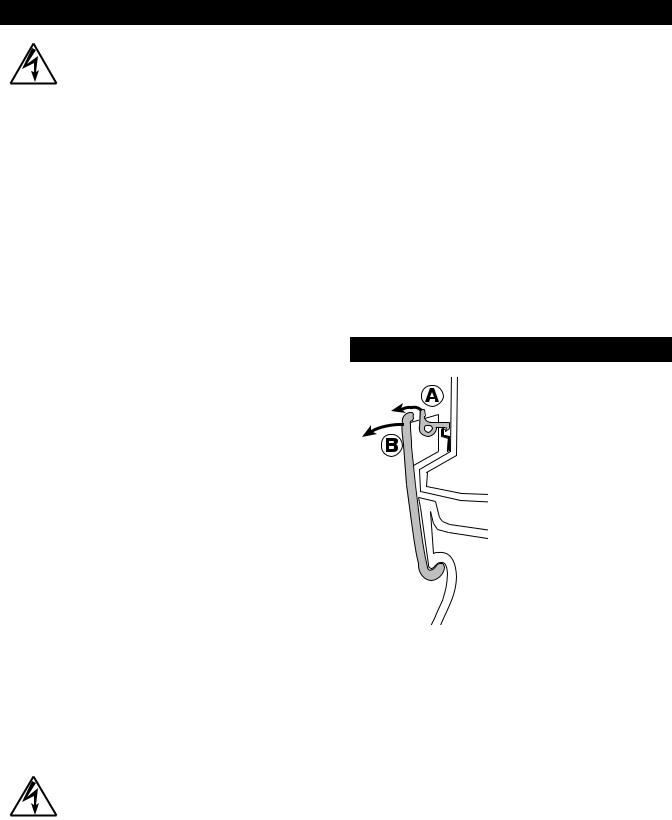
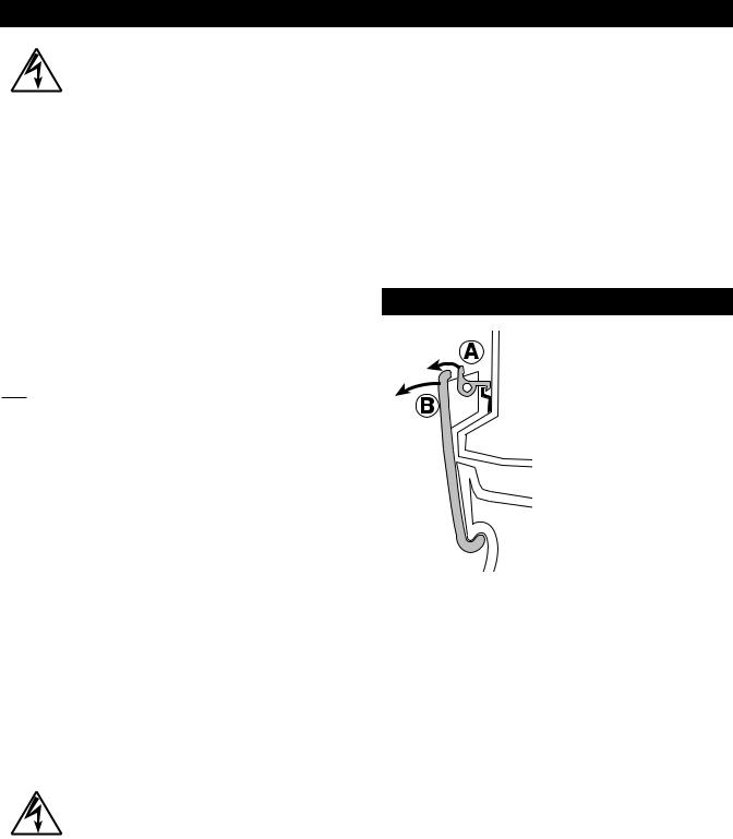
To open and close your Passport system, simply follow these guidelines:
TRANSPORTATION LATCHES
1. Place your finger tip under the safety latch and gently lift. When the safety latch has disengaged, lift both the latches clear on each speaker before attempting to remove the speaker.
2. To replace, position each speaker on the tower foot and bring the speaker in to close the engagement with the tower and latches. Position the latch hooks over the speaker notch and close the latches. The 4 latches will automatically engage.
Note: These parts are precision engineered and no force is needed to secure them. Careful alignment of parts will ensure easy operation.
2
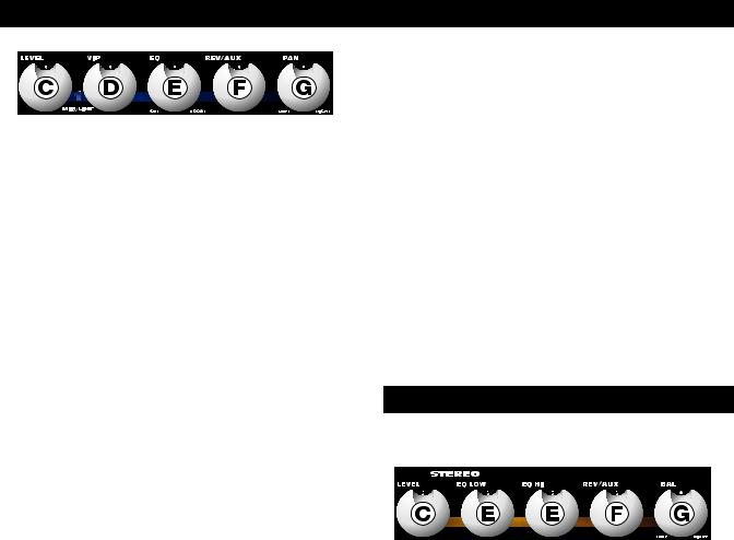
MONO MIC / LINE CONTROL FUNCTIONS
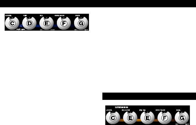
C.LEVEL – Adjusts the volume level of the individual channel. Rotating the knob clockwise increases the respective channel’s contribution to the “Main Out” mix, while rotating it counterclockwise decreases the volume. Adjust this control after the Passport’s master output level volume has been set.
D.VIP (CHANNEL 1 ONLY) – The VIP or Vocal Input Priority control adjusts the level at which the volume of all other channels are automatically reduced in favor of the source attached to the Mic/Line Input 1. This unique feature permits a user to speak while other inputs (such as background music) continue at temporarily reduced levels. The VIP circuit is “pre-volume control” which means it is effective regardless of level control setting of channel one. Adjust this control while speaking into a microphone on channel 1, with other program material input through another channel. Depending on the duration and level of the signal being input to Mic/Line 1 and the position of the control, the VIP circuit will trigger a reduction in level of all the other channels. The original levels will be automatically restored when there is no signal present on channel 1. In typical use, the circuit will return normal levels in about 4 seconds. With the level set at a higher or a stronger signal, normal levels will be restored after approximately 6 seconds. The VIP circuit has an intentionally slow release time which prevents interruptions when a speaker pauses for thought or effect. Care should be taken to avoid the VIP triggering on sound from the main speakers. At high settings, the microphone may “hear” the main system speakers and trigger a reduction in level. When not using the VIP feature, be sure to turn the control completely counterclockwise.
E.EQ – Adjusts the amount of frequency increase or decrease in the channel. Rotating the knob counterclockwise increases the bass frequency response while simultaneously decreasing the high frequency response. Likewise, rotating the knob clockwise increases the treble or high frequency response while simultaneously decreasing the bass or low frequency response. When the tone controls are set at their notched or straight up position, the channel response is “flat” with no frequencies increased or decreased. To set the EQ, start with this control in the 12 o’clock (notched) position. Simply turn the control until things sound good!
F.REV/AUX – Adjusts the amount of signal sent to the Reverb processor, and to the Rev/Aux output jack. Reverb can be used to enhance the sound quality of any performance where appropriate and desired. In the full
left position there is no level sent to the reverb processor or Rev/ Aux jack. Care should be taken to set the Reverb return master control to a middle position or above, before adjusting levels from the individual channels. When the reverb/auxiliary mix is set, overall levels of reverb can be adjusted at the master control.
Keep in mind that while Reverb or effects can enhance a musical performance or presentation. Too much reverb can make the same performance or presentation unintelligible or “muffled”. Keep your audience in mind when setting reverb levels.
G. PAN – The Pan control features a notched position indicator and adjusts the perceived “position” of the mono signal from the input within the stereo field created by the two speaker cabinets. Full Left or Right rotation of this control sends the signal to the that channel only, with no signal sent to the other. The center position sends the same amount of signal to both
STEREO CONTROL FUNCTIONS
speakers.
C. STEREO INPUT LEVEL – Adjusts the volume level of the stereo input channel. Rotating the knob clockwise increases the stereo input channel’s contribution to the “Main Out” mix, while rotating it counterclockwise decreases the volume. Adjust this control after the Passport’s master output level volume has been set.
E. EQ LOW – Adjusts the relative level of the low frequency content for the stereo channel. Rotating the knob counterclockwise decreases the bass or low frequency response. Likewise, rotating the knob clockwise increases the bass or low frequency response.
E. EQ HI – Adjusts the relative level of the high frequency content. Rotating the knob counterclockwise decreases the treble or high frequency response. Likewise, rotating the knob clockwise increases the treble or high frequency response. When the EQ controls are set at their notched or straight up position, the channel frequency response is “flat” with no frequencies increased or decreased.
3
F.REV/AUX – Adjusts the amount of signal sent to the internal Reverb processor, and to the Rev/Aux output jack. In the full left position the control is effectively off. Care should be taken to set the Reverb return master control to a middle position or above, before adjusting levels from the individual channels. When the reverb/auxiliary mix is set, overall levels of reverb can be adjusted at the master control.
G.BAL – The balance control features a notched position indicator and adjusts the perceived “position” of the mono signal from the input within the stereo field created by the two speakers. Full Left or Right rotation of this control sends the signal to the that channel only, with no signal sent to the other. The center position sends the same amount of signal to both speakers.
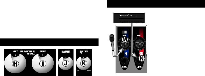
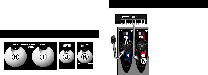
MASTER CONTROL FUNCTIONS
H & I. MASTER VOLUME LEVEL CONTROLS – The Left and Right Master Volume Controls adjust the output volume of the PD-150. The Master controls feature notched position indicators. For the majority of applications the Passport system has been balanced to operate with these controls at their notched 12 o’clock positions. In situations where more volume is required the master controls can provide an additional 6 dB of gain when turned to the right of the center position.
Set the system up in the normal manner and adjust levels as necessary. Raise the master volume controls beyond their 12 o’clock positions only after increasing the individual channel level controls.
Passport’s internal amplifiers have on-board processing designed to optimize the system’s performance when used with the custom designed PD-150 speakers.
J.MASTER REVERB – Adjusts the amount of reverb signal level sent to the mix or output. Rotating the knob clockwise increases the reverb signal sent to the main mix. When the knob is in its full counterclockwise position, there is no reverb heard in the mix.
K.SYSTEM EQ – Adjusts the overall amount of frequency increase or decrease on the Passport. Rotating the knob counterclockwise increases the bass frequency response while simultaneously decreasing the high frequency response. Likewise, rotating the knob clockwise increases the high frequency response while simultaneously decreasing the bass frequency response. When the system EQ control is set at its notched or straight up position, the channel response is “flat” with no frequencies increased or decreased. To
set the System EQ, start with this control in the 12 o’clock (flat) position. Simply turn the control until things sound good!
You will notice that the input jacks and channel controls are color coded. This is done to easily identify which set of controls is associated with which input connections.
MIC / LINE / STEREO INPUTS
A. LINE / MIC SWITCH – This 


 switch allows you to select gain


 levels for either a microphone or line level source. When the


 switch is in the line position, the
input level is optimized for items
such as guitars, keyboards,
drum machines, outboard
effects, etc. When the switch is
in the mic position, the input
level is optimized for most
commonly used microphones. No harm will come to the circuitry if the switch is in the
wrong position. However, for optimum performance, be sure to use the mic position when a microphone is plugged into the respective channel and the line position when an item using a line level signal is used.
M.MIC INPUT JACK – Plug your microphone in here. This three pin XLR balanced female input connector is intended for input signals from low impedance microphones.
N.LINE INPUT JACK – Plug your instrument in here. This 1/4 inch balanced input jack suited for use with items having a line level output such as high impedance microphones, keyboards, drum machines, outboard effects, etc. It accepts both balanced and unbalanced cables.
O.AUX LINE INPUT (Ch. 3) – Input 3 features a pair of RCA input connectors that allow an additional line level stereo source to be input to the system. These connectors SUM, or add, the two input signals together (mono) and send them to the mix in exactly the same way as the normal Line inputs. Note: These connectors are set at a constant "line level" are not effected by the Mic/Line "gain" select switch.
4
P. STEREO/ 


 MONO SWITCH


 – This switch allows you to


 select between a
stereo or mono
input from either
the RCA or 1/4”
stereo input
jacks. This switch


 should be set to the Mono position when a source such as a guitar is input to this
channel, thus allowing the mono source to be applied to both outputs at the same level. Failure to do this will result in the input source only appearing at one of the outputs. When the switch is in the stereo position, the full stereo field is heard.
Q. RCA (STEREO) INPUTS – Stereo phono (RCA) input jacks designed for use with a tape player, CD player, or any other stereo source. Use these jacks for connecting the output of a computer sound card or other similar device to your Passport. Adapters that convert an 1/8” male plug to RCA male phono plugs are readily available at electronics stores. Note: These connectors are set at a constant “line level”.
G. STEREO – This 1/4” TRS jack is wired for Tip=Left, Ring=Right and Sleeve=Ground, the standard format of commercially available cables. The sensitivity of this input is suited for playback devices such as CDs, Cassettes, DAT or Mini Disc. Outputs from instruments such as keyboards can also be used here (refer to item O).
S. TAPE OUT – The Tape Out RCA jacks provide a mix output that is independent of the Master Level Controls. Connect these to the inputs of a recording device, such as a cassette or DAT recorder, to record your event. Changes made during the performance, to the input level controls, channel EQ, and reverb controls will be heard in the Tape Out mix. Changes made to the master level controls will not effect the level of the recording. Adjust recording levels according to the instructions on your recording device.
R. AUX SEND – Plug your external effects signal processor in here. Although the Passport is already equipped with on-board digital reverb, an external effects signal processor can be incorporated into the Passport’s signal flow. This 1/4 inch output jack is designed to feed the Passport’s effects bus signal to an external signal processing device, such as a digital delay or a chorus.
AUX AND FOOTSWITCH JACKS
T.AUX RETURN – Plug your external effects signal processor’s output signal in here. This 1/4 inch input stereo jack is designed to accept signals from an external processing device, such as a digital delay or a chorus unit. This input can also be used as a stereo input with the volume controlled at the master volume knobs.
U.FOOT SWITCH – The Footswitch connector allows the internal reverb return to be muted, or shut off, through the use of a simple foot operated switch (Fender part number 099-4052-000). The footswitch should be wired to connect the tip to the sleeve to turn the reverb off, and requires a standard speaker or instrument cable.
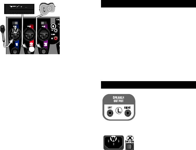
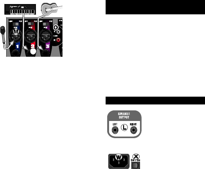
REAR PANEL
L. SPEAKER OUTPUTS – These are speaker level (powered) output jacks designed to feed each of your Passport speaker
enclosures. Use the enclosed
cables (or other speaker cable) to connect the Passport’s speakers
to the power tower.
X. POWER SWITCH – Turns the AC power ON and OFF. When the switch is in the OFF position, your Passport is completely shut down.
W. AC CONNECTOR/ LINE CORD – The Passport is equipped with a grounding type IEC supply cord to reduce the possibility of shock hazard. Be sure to connect it to a grounded AC receptacle. DO NOT ALTER THE AC PLUG.
The power mains (AC) fuse and fuse holder are under the IEC (power cord) socket. Replacement fuses must be of the same rating (T4A, 250V) and size as originally equipped. To replace a blown fuse, remove the IEC power cord. Pull out the fuse holder and find the spare fuse inside.
Your Passport system is capable of running on battery power. The off-white plastic connector on the rear of your Passport is the DC power input connector for connecting the Passport DC-DC converter. The converter is then connected to a battery. Available accessories include the Passport DC-DC converter (Fender part number 069-1002-000) and 12 volt battery pack (Fender part number 069-9003-000).
5

REAR STORAGE COMPARTMENT
A small storage compartment can be found on the rear of the Passport tower. To access this compartment, simply lift the latch and pull open the storage door. This compartment is ideal for storing cables, microphones or other items when you are transporting your Passport.
On the back panel of the storage compartment you will see a narrow metal strip with a screw on either end. This is the protective cover for the wireless adapter terminal. Custom wireless systems are available for your Passport. The receiver for the wireless system installs in the storage compartment.
SET-UP AND CONNECTIONS
Before turning on the Power, read and heed the safety warnings on page 2.
It is wise to establish a routine for connecting and powering up your sound system. Provided you have a properly grounded AC outlet or outlet strip with sufficient power handling capacity, plug all sound system equipment into the same outlet or strip. This will enhance system safety and performance. Take care that the AC circuit is capable of handling the peak power demands of your system. Consult the product handbooks or a qualified electrician if in doubt.
When setting up, be sure to follow these simple set-up guidelines:
1.First, turn all channel Level, VIP (channel 1 ONLY) and Rev/Aux controls to their full counterclockwise (OFF) positions. Next, place all EQ, Pan and Master controls at 12 o’clock in their center notched positions. Be sure to set the appropriate input (mic/line switch position) for the source you are setting up.
2.Next, connect each speaker cable to the appropriate Left & Right Speaker outputs on the rear tower and on each speaker front panel with the enclosed cables.
3.Connect all sources such as microphones, tape decks, keyboards etc., into the appropriate inputs.
4.Finally, check the local voltage and set the voltage selector switch located adjacent to the power input socket on the rear of the mixer / amplifier to the appropriate operating range. (See Safety Precautions on page 2.) Plug the power cable into the IEC (power cord) socket on the rear of the Passport Tower and connect the other end to a properly grounded 3 wire AC power outlet.
POWERING UP
Turn the Power Switch to the ON position. The Power LED will illuminate green and the system will turn on. If other powered equipment is to be attached to the system, it is always advisable to turn on your Passport last. In this way any transient spikes and thumps caused by other equipment will not be amplified and sent to your system speakers. For the same reasons it is advisable to turn off your Passport system first before turning off the attached equipment.
Should the Power LED not illuminate when the rear panel power switch is operated, check your power connections and retry. Should the Power LED still fail to illuminate after you have confirmed the power connections, disconnect all cables and check the Passport fuses. Be sure to replace any blown fuses with fuses of the correct value. Reconnect the power and speaker cables and turn the rear panel power switch on.
Re-set the system by turning on the power switch. If the Power LED illuminates red, the system is indicating a thermal protect mode or cooling problem. Be sure to check the air inlet filter at the base of the unit by removing it and making sure it is clear of debris.
Turn power off and wait for a few minutes allowing heat to dissipate and the Passport to reset itself. If after doing so the Power LED continues to glow red this indicates a fault with your system and you should consult an authorized Fender service center.
If no audio is present in one of the speakers, check to see if your control settings are correct. Next, unplug the cable from your working speaker and reconnect it to the other speaker. If the second speaker now works, this indicates that the first cable is bad, and should be repaired or replaced.
SET-UP SYSTEM VOLUME AND LEVELS
To set system volume and operating levels, be sure to follow these simple set-up guidelines:
1.First, slowly raise the large Left and Right Master volume controls to their 12 o’clock notched positions.
2.Use a microphone (or other source) in the same position as it will be used on stage and in the manner in which it will be used for the event. Slowly bring up the appropriate channel input level control listening for the onset of feedback or howling or until the required level is reached. Have a helper “walk” the audience area to make sure coverage and levels are sufficient for your needs. The system’s overall volume can be raised simply by rotating the Left and Right Master volume controls to the desired level.
6

3. Consider the application and needs of the event and set the System EQ control as appropriate. This is best achieved by playing recorded material of the same type as your show program, or by having an assistant speak into the microphone while you listen in the audience area.
For public address (spoken voice), it is advisable to rotate the System EQ control clockwise to enhance the mid and high frequencies, and limit the low frequency content. For large outdoor spaces this will also give the maximum headroom and output capability. Carefully consider the individual event’s needs and set your control for the maximum effect.
POWER TOWER™
In setting up the system, the Passport Mixing console should ideally be placed where system performance can be evaluated by the operator. If no ongoing adjustments will be necessary, the mixer may be placed conveniently and where the cable lengths allow.
Take care to place the Power Tower where the cables will not trip anyone. All cables should be carefully secured.
The storage compartment in the rear of the Tower can hold cables, microphones and other system parts. To open simply slide the catch upwards and pull open.
The mains (AC) fuse holder is under the IEC (power cord) socket on the right rear of the Tower. To change a fuse, remove the IEC plug and, using an appropriate tool pull out the fuse holder. Note there is a spare fuse in the fuse holder; the Passport utilizes a T4A, 250V fuse. Only replace fuses with one of an identical value and size.
The Passport System is weather resistant in its packed transport mode. However, when operating outdoors, take care to fully protect the Power Tower in the event of exposure to rain. Remember to allow free air flow through the front air inlet located at the bottom of the front panel on the Passport power tower.
SPECIFICATIONS
Part Number
069-2005-0X3
Frequency Response
20 Hz to 40 kHz ± 1 dB (at send output) 30 Hz to 30 kHz ± 1 dB (at speaker output, with processor threshold exceeded)
Distortion
< 0.1%, 20 Hz to 20 kHz, 1 dB below rated output
System Signal to Noise Ratio
> 80 dB @ 1 w, “A” WTD
Power Output
75W/ch continuous average power, 8ohm, both channels driven with THD < 1 %
Input Impedance (Channels 1-2-3 XLR and 1/4”)
“Mic” switch position: 2 k ohm “Line” switch position: 66 k ohm
Input Impedance (Phono and Stereo Channel 1/4”)
78 k ohm
Max. Input Level
Mic: -7 dBu
Line: 30 dBu
Stereo: 26 dBu
Return Input Impedance
47k ohm
Fuse type
T4A, 250V
Passport System
Width: 610 mm (24 in.)
Height: 541 mm (18 in.)
Depth: 254 mm (10 in.)
Weight: 11.83 kgs (26 lbs)
Speakers
Width: 245 mm (9.65 in.)
Height: 439 mm (17.5 in.)
Depth: 241 mm (9.5 in.)
Weight: 3.3 kgs (7.25 lbs)
Power Tower
Width |
254 mm (10 in.) |
Height |
451 mm (18 in.) |
Depth |
178 mm (7 in.) |
Weight |
5.23 kgs (11.5 lbs) |
Tower Footprint
241 x 298 mm (9.5 x 11.75 in.)
Microphone
Dynamic Cardioid, balanced
Microphone Cable
XL -Male to XL-Female, 6 m (20 feet)
Speaker Cables
1/4 in. to 1/4 in., 9 m (30 feet)
0 dBu is referenced to 0.775 volts rms
7
VISIT US ON THE WEB – For information on all of Fender’s Passport and Fender Audio products, go to www.fenderaudio.com.
PASSPORT ACCESSORIES – A complete line of accessories are available for your Passport Sound System. Contact your local dealer or visit our website for more information.
ST275 SPEAKER STAND KIT – Includes 2 heavy duty, lightweight aluminum speaker stands and a carry bag.
Part Number 069-9001-000
ST280 STAND KIT – Includes 2 heavy duty, lightweight aluminum speaker stands, two tripod microphone stands and a carry bag.
Part Number 069-9008-000
P51 MICROPHONE KIT – Contains one dynamic cardioid microphone, mic clip, mic cable and vinyl carry pouch.
Part Number 069-9000-000
DC-DC CONVERTER – Necessary for running your Passport system off battery power.
Part Number 069-9002-000
PASSPORT BATTERY PACK – Deep-cycle 12v battery capable of running a Passport system for up to 6 hours on a single charge. (note must use the DCDC converter when running a Passport off a battery). Part Number 069-9003-000
DC ACCESSORY BAG – Custom designed carry bag for the DC-DC Converter and Passport Battery Pack. Part Number 069-9009-000
PASSPORT P-150 PROTECTIVE COVER – Padded vinyl cover for your Passport P-150 and PD-150 system.
Part Number - 069-9010-000
DUAL SPEAKER MOUNT – Adapter for mounting two speakers on a single speaker stand.
Part Number - 069-9007-000
WALL MOUNT ADAPTER – A single heavy duty wallmount bracket for mounting a Passport speaker for installation.
Part Number - 069-9006-000
PASSPORT HAND HELD WIRELESS SYSTEM – Custom designed wireless system for use with Passport sound systems. Once installed, this system becomes a permanent part of your sound system. Includes a hand held electret condenser microphone and receiver module.
Part Number - 069-1201-00x (x indicates frequency)
PASSPORT EXECUTIVE WIRELESS SYSTEM – Custom designed wireless system for use with Passport sound systems. Once installed, this system becomes a permanent part of your sound system. Includes a receiver module, and a belt pack transmitter with interchangeable headset, lavalier and instrument cable elements. Custom molded carry case included.
Part Number - 069-1205-00x (x indicates frequency
FENDER DYNAMIC CARDIOID MICROPHONE - High quality, dynamic cardioid hand held microphone. Includes mic clip.
Part Number - 069-9012-000
A PRODUCT OF:
FENDER MUSICAL INSTRUMENTS CORP.
CORONA, CA USA
Printed in China
Fender Passport PD-150
Sistema de sonido portátil Deluxe
INTRODUCCION
150 vatios de nítido sonido estéreo
Altavoces de diseño personalizado que utilizan la última tecnología en altavoces de alto rendimiento
Reverberación digital incorporada
El sistema VIP™ (Vocal Input Priority, prioridad de entrada vocal) permite a la entrada uno anular todas las demás entradas cuando exista una señal en la entrada uno
Tres micrófonos mono / Entradas de línea con XLR y conexiones de entradas con balance de 1/4 pulgadas
Entrada estéreo con conexiones RCA de 1/4 pulgadas
El suministro de corriente del modo de encendido permite utilizarlo en cualquier lugar del mundo
Todo lo que necesita para empezar:
–Amplificador mezclador de Passport
–Un micrófono dinámico y 6m (20 pies) de cable
–Dos cables de altavoz de 9 m (30 pies)
–Cable de alimentación IEC
–Dos cajas acústicas de gama completa
–Caja para transportar el equipo completo
Este símbolo advierte al usuario que en el interior de la carcasa hay niveles peligrosos de voltaje.
Este símbolo advierte al usuario que lea toda la documentación adjunta para utilizar la unidad con seguridad.
Enhorabuena por haber adquirido un sistema de sonido portátil autónomo Fender Passport PD-150 de alto rendimiento. El equipo Passport incluye todo lo que necesita para producir un sonido excelente … En cualquier lugar.
Transporte el equipo del mismo modo en que llevaría una maleta de tamaño mediano. Abra los pasadores del altavoz y encontrará dos cajas de altavoces de gama completa, un mezclador y un micrófono dinámico, además de todos los cables necesarios para empezar a utilizar el sistema. Utilice el equipo para amplificar voces, instrumentos musicales, tarjetas de sonido, reproducciones de cintas y CD, y mucho más. La fácil y rápida instalación de Passport, su capacidad para cubrir grandes audiencias y su sencillo funcionamiento son los distintivos de esta innovadora línea de productos.
El panel de control de Passport dispone de tres entradas de línea/micro mono y un canal estéreo (cuatro canales en total). El canal de entrada estéreo se puede utilizar tanto para su funcionamiento en estéreo como en mono, lo cual proporciona una magnífica flexibilidad del uso de las entradas. Además, la revolucionaria tecnología en altavoces de cada caja acústica proporciona un sonido de gama completa increíblemente nítido, con una extraordinaria cobertura de audiencia. El mezclador de alimentación independiente proporciona un total de 150 vatios de sonido estéreo de alta calidad.
En el caso del uso vocal del sistema, la función VIP (Vocal Input Priority) de Passport se puede utilizar para reducir o “bajar” el nivel de la música de fondo mientras se habla y, a continuación, restablecer la música una vez que se haya terminado de hablar. Experimente con los controles de tono, la reverberación digital y la ubicación del altavoz y descubrirá la increíble potencia y versatilidad de Passport.
IMPORTANTES SALVAGUARDIAS:
–ADVERTENCIA : PARA EVITAR DAÑOS, INCENDIOS Y DESCARGAS ELÉCTRICAS, NO EXPONGA ESTA UNIDAD A LA LLUVIA NI A LA HUMEDAD.
–CONTIENE PIEZAS CUYO MANTENIMIENTO NO LO PUEDE REALIZAR EL USUARIO, SINO SÓLO PERSONAL CUALIFICADO.
–ESTA UNIDAD DEBE CONECTARSE CON TOMA DE TIERRA.
9
PRECAUCIONES DE SEGURIDAD
El sistema de sonido Fender Passport incluye un cable de alimentación desmontable con un conector IEC hembra y un conector macho de CA. El cable de alimentación se suministrará con
un tipo u otro de conector macho de CA, dependiendo del territorio donde se adquirió el sistema Passport, para ajustarse a los distintos requisitos de seguridad y de código de cada país concreto. Todos los cables de CA que se proporcionan con los productos de Passport poseen tres clavijas.
En ningún caso se desconectará ni retirará la clavija de conexión.
El sistema Passport dispone de un suministro de corriente del modo de encendido diseñado para funcionar con cualquier voltaje de CA y con cualquier frecuencia de línea, para transformar la corriente alterna con la máxima eficacia.
Antes de viajar al extranjero con el sistema Passport, compruebe siempre el voltaje local como medida de precaución y coloque el conmutador de selección de voltaje, situado junto a la toma de corriente en la parte trasera del amplificador / mezclador, en el rango de operatividad adecuado. Esta comprobación debe realizarse antes de conectar el cable de alimentación. El sistema Fender Passport posee dos posiciones de voltaje: 115 V o 230 V.
En caso de no seleccionar el rango de voltaje adecuado, la unidad entrará en el modo de protección, se anularán todas las garantías y la unidad puede resultar dañada.
Por ejemplo, el estándar en Estados Unidos es 117 voltios/ 60 Hz, mientras que en Japón es 100 voltios/50 Hz. Para ambos países el conmutador de selección de voltaje deberá colocarse en la posición 115 V. El estándar en los países europeos es 230 voltios/50 Hz; sin embargo, se utilizan distintos tipos de enchufes. Para todos estos países, el conmutador de selección de voltaje deberá colocarse en la posición 230 V. Si utiliza adaptadores de enchufe o utiliza la unidad en un territorio distinto a donde la adquirió, tenga mucho cuidado de cumplir los requisitos de seguridad locales, así como los códigos eléctricos en uso.
Si no está seguro de cuál es el voltaje local, los colores y códigos de los cables, la toma de CA o los procedimientos correctos de conexión, consulte a un técnico cualificado.
Advertencia
No saque ni desconecte en ningún caso la clavija de conexión de Passport ni de cualquier otra pieza del equipo eléctrico. Es posible que, en determinadas circunstancias, una combinación
de distintos tipos de equipos que no dispongan de toma de tierra cree un alto riesgo de descarga eléctrica. Los micrófonos tienen fundas metálicas y están conectados a través de un cable al chasis del mezclador. El mezclador de Passport estará conectado a tierra correctamente si el cableado del edificio se adecua al código y si la clavija de conexión de la toma de CA está correctamente conectada. Sin embargo, si por cualquier motivo el equipo externo conectado a CA con conexiones CA sin toma de tierra se utiliza junto con el sistema Passport (por ejemplo, un amplificador de música que no disponga de toma de tierra),
puede haber una diferencia de potencial en la funda del micrófono. Si se da dicha combinación, un intérprete que sostenga un micrófono (con toma de tierra) que esté haciendo contacto con un elemento sin toma de tierra del equipo puede estar expuesto a peligrosas descargas eléctricas.
Si se siguen los procedimientos correctos y se respetan las precauciones de seguridad, se pueden minimizar los riesgos de descargas eléctricas graves. Compruebe siempre la conexión de CA y, sobre todo el voltaje, entre el micrófono y cualquier otro equipo CA. Lo mejor es evitar el uso del sistema junto con un equipo eléctrico que no disponga de toma de tierra o cuya conexión no sea adecuada.
Para abrir y cerrar el sistema Passport, sólo tiene que seguir estas instrucciones:
PASADORES DE TRANSPORTE
1.Deslice la punta del dedo bajo el pasador de seguridad y le-
vántelo con cuidado. Cuando éste se haya soltado, levante ambos pasadores de cada altavoz antes de intentar sacarlo.
2.Para volver a colocarlo, sitúe cada altavoz sobre el pie de la torre e introdúzcalo para cerrar el acoplamiento con la torre y los pasadores. Sitúe los ganchos de los pasadores sobre la ranura del altavoz y cierre los pasadores. Los 4 pasadores se acoplarán automáticamente.
Nota: Estas piezas están fabricadas con gran precisión, por lo que no es necesario forzarlas para asegurarlas. Si se colocan las piezas con cuidado, el funcionamiento será sencillo.
10
FUNCIONES DE CONTROL DE LINEA / MICROFONO MONO
C.LEVEL (NIVEL) – Ajusta el nivel de volumen del canal individual. Al girar este mando a la derecha aumenta la contribución de cada canal a la mezcla de salida principal “Main Out”, mientras que si se gira en el sentido contrario, disminuye el volumen. Ajuste este control una vez que haya establecido el volumen principal del nivel de salida de Passport.
D.VIP (CHANNEL 1 ONLY) [VIP (SOLO CANAL 1)] – El control VIP (Vocal Input Priority) ajusta el nivel al cual se reduce de forma automática el volumen de todos los demás canales en favor de la fuente asignada a la entrada 1 de línea/micrófono. Esta función exclusiva permite al usuario hablar mientras otras entradas (como la música de fondo) continúan a niveles reducidos temporalmente. El circuito VIP es “previo al control de volumen”, lo que significa que es eficaz independientemente del valor del control de nivel del canal uno. Ajuste este control mientras habla por un micrófono en el canal 1, con otra entrada de material de programa a través de otro canal. Dependiendo de la duración y del nivel de la señal que entre a través de la línea/micrófono 1 y de la posición del control, el circuito VIP producirá una reducción del nivel en todos los demás canales. Los niveles originales se restablecerán cuando no haya ninguna señal en el canal 1. En condiciones normales, el circuito recobra sus niveles normales en unos 4 segundos. Si el nivel se encuentra en una señal más alta o más fuerte, los niveles normales se restablecerán al cabo de unos 6 segundos. El circuito VIP posee un tiempo de relajación deliberadamente lento, que evita las interrupciones cuando un hablante hace una pausa para pensar o para causar algún efecto. Procure evitar que el sonido de los altavoces principales se active mediante el circuito VIP. Si los niveles son altos, el micrófono puede “oír” los altavoces principales del sistema y producir una reducción del nivel.
Cuando no utilice la función VIP, asegúrese de girar el control completamente a la izquierda.
E.EQ (ECUALIZACIÓN) – Ajusta la cantidad de aumentos y disminuciones de frecuencia del canal. Al girar el mando a la izquierda, disminuye la respuesta de frecuencia de los bajos o graves. Asimismo, al girar el mando a la derecha, aumenta la respuesta de frecuencia de los altos o agudos, mientras que la respuesta de frecuencia de los bajos o graves disminuye simultáneamente. Cuando los controles de tono se encuentran en posición apuntando hacia arriba, la respuesta del canal es “plana”, es decir, sin aumentos ni disminuciones de las frecuencias. Para ajustar el ecualizador, empiece situando este control en la posición (marcada) de las 12 en punto. Después, sólo tiene que girar el control hasta conseguir un buen sonido.
F.REV/AUX – Ajusta la cantidad de señal enviada al procesador de reverberación y al conector de salida Rev/Aux. La reverberación se puede utilizar para mejorar la calidad de sonido de cualquier interpretación de forma adecuada y como desee. Si está girado completamente hacia la izquierda, no se envía ningún nivel al procesador de reverberación ni al conector Rev/Aux. Procure ajustar el control principal de
retorno de reverberación a una posición media o por encima, antes de ajustar los niveles de los canales individuales. Una vez establecida la mezcla de reverberación/auxiliar, se pueden ajustar los niveles globales de reverberación con el control principal. Tenga en cuenta que, si bien la reverberación o los efectos pueden mejorar una presentación o interpretación musical, demasiada reverberación puede hacer que dicha presentación o interpretación sea ininteligible o “distorsionada”. Tenga en cuenta a la audiencia a la hora de ajustar los niveles de reverberación.
G. PAN – El control Pan dispone de un indicador de posición y ajusta la “posición” percibida de la señal mono desde la entrada dentro del campo estéreo creado por las dos cajas de altavoces. Si se gira este control completamente hacia la izquierda o hacia la derecha, la señal se enviará sólo a ese canal y no se enviará ninguna señal al otro. Si el control está en la posición central, se enviará la misma cantidad de señal a ambos altavoces.
FUNCIONES DE CONTROL ESTEREO
C. STEREO INPUT LEVEL (NIVEL DE ENTRADA ESTEREO) – Ajusta el nivel de volumen del canal de entrada estéreo. Al girar este mando a la derecha aumenta la contribución del canal de entrada estéreo a la mezcla de salida principal “Main Out”, mientras que si se gira en el sentido contrario, disminuye el volumen. Ajuste este control una vez que haya establecido el volumen principal del nivel de salida de Passport.
E. EQ LOW (ECUALIZACION DE GRAVES) – Ajusta el nivel relativo del contenido de baja frecuencia para el canal estéreo. Al girar el mando a la izquierda, disminuye la respuesta de frecuencia de los bajos o graves. Asimismo, al girar el mando a la derecha, aumenta la respuesta de frecuencia de los bajos o graves.
E. EQ HI (ECUALIZACION DE AGUDOS) – Ajusta el nivel relativo del contenido de alta frecuencia. Al girar el mando a la izquierda, disminuye la respuesta de frecuencia de los altos o agudos. Asimismo, al girar el mando a la derecha, aumenta la respuesta de frecuencia de los altos o agudos. Cuando los controles de ecualización se encuentran en posición apuntando hacia arriba, la respuesta del canal de frecuencia es “plana”, es decir, sin aumentos ni disminuciones de las frecuencias.
11
F.REV/AUX – Ajusta la cantidad de señal enviada al procesador de reverberación interno y al conector de salida Rev/Aux. El control estará desactivado si se gira completamente hacia la izquierda. Procure ajustar el control principal de retorno de reverberación a una posición media o por encima, antes de ajustar los niveles de los canales individuales. Una vez establecida la mezcla de reverberación/auxiliar, se pueden ajustar los niveles globales de reverberación con el control principal.
G.BAL (BALANCE) – El control de balance dispone de un indicador de posición y ajusta la “posición” percibida de la señal mono desde la entrada dentro del campo estéreo creado por los dos altavoces. Si se gira este control completamente hacia la izquierda o hacia la derecha, la señal se enviará sólo a ese canal y no se enviará ninguna señal al otro. Si el control está en la posición central, se enviará la misma cantidad de señal a ambos altavoces.
FUNCIONES DE CONTROL PRINCIPALES
H & I. MASTER VOLUME LEVEL CONTROLS (CONTROLES PRINCIPALES DE NIVEL DE VOLUMEN) – Los controles principales de volumen izquierdo y derecho ajustan el volumen de salida del PD-150. Los controles principales disponen de indicadores de posición. Para la mayoría de las aplicaciones, el sistema Passport ha sido ajustado para que funcione con estos controles en la posición de las 12 en punto. En situaciones en las que se requiere más volumen, los controles principales pueden proporcionar un aumento adicional de 6 dB si se giran hacia la derecha de la posición central.
Prepare el sistema de la forma habitual y ajuste los niveles como sea necesario. Aumente los controles principales de volumen para que sobrepasen las posiciones de las 12 en punto, pero sólo cuando haya aumentado los controles de nivel de canal individual.
Los amplificadores internos de Passport poseen procesamiento incorporado diseñado para optimizar el rendimiento del sistema cuando se utilice con los altavoces de diseño personalizado PD-150.
J.MASTER REVERB (REVERBERACION PRINCIPAL) –
Ajusta la cantidad de nivel de señal de reverberación enviado a la mezcla o salida. Al girar el mando a la derecha aumenta la señal de reverberación enviada a la mezcla principal. Cuando el mando haya alcanzado la posición máxima a la izquierda, no se escuchará reverberación en la mezcla.
K.SYSTEM EQ (ECUALIZACION DEL SISTEMA) – Ajusta la cantidad global de aumentos y disminuciones de frecuencia del sistema Passport. Al girar el mando a la izquierda aumenta la respuesta de frecuencia de los graves, mientras que la respuesta de frecuencia de los agudos disminuye simultáneamente. Asimismo, al girar el mando a la derecha aumentará la respuesta de frecuencia de los agudos, mientras que la respuesta de frecuencia de los graves
disminuirá simultáneamente. Cuando los controles de ecualización del sistema se encuentran en posición apuntando hacia arriba, la respuesta del canal es “plana”, es decir, sin aumentos ni disminuciones de las frecuencias. Para ajustar el ecualizador del sistema, empiece situando este control en la posición (plana) de las 12 en punto. Después, sólo tiene que girar el control hasta conseguir un buen sonido.
Observe que los conectores de entrada y los controles de canal están codificados por colores. Con esto se pretende identificar fácilmente qué conjunto de controles se asocia a cada conexión de salida.
ENTRADAS LINEA / MICROFONO / ESTEREO
A. LINE / MIC SWITCH (CONMUTADOR EN LINEA / MICROFONO) – Este conmutador permite seleccionar los niveles de ganancia
de un micrófono o fuente de nivel
de línea. Si el conmutador está en
la posición de línea, el nivel de
entrada está optimizado para
instrumentos como guitarras,
teclados, cajas de ritmo, efectos
externos, etc. Si el conmutador
está en la posición de micrófono, el
nivel de entrada está optimizado


 para los micrófonos más comunes. Si el conmutador está en la posición equivocada no afectará a los circuitos. Sin embargo,
para obtener un rendimiento óptimo, asegúrese de utilizar la posición de micrófono cuando haya un micrófono conectado en el canal correspondiente y la posición línea cuando se utilice un elemento que emplee una señal de nivel de línea.
M.MIC INPUT JACK (CONECTOR DE ENTRADA DE MICROFONO) – Conecte el micrófono aquí. Este conector de entrada con balance XLR de tres clavijas está diseñado para señales de entrada de micrófonos de baja impedancia.
N.LINE INPUT JACK (CONECTOR DE ENTRADA DE LINEA) – Conecte el instrumento aquí. Este conector de entrada con balance de 1/4 pulgadas es adecuado para su uso con elementos que tengan una salida de nivel de línea, tales como micrófonos de alta impedancia, teclados, cajas de ritmo, efectos externos, etc. Admite tanto cables con balance como sin balance.
O.AUX LINE INPUT (Ch. 3) [ENTRADA AUXILIAR DE LINEA (canal 3)] – La entrada 3 dispone de un par de conectores de entrada RCA que permiten añadir al sistema una fuente estéreo de nivel de línea adicional. Estos conectores SUMAN las dos señales de entrada (mono) y las envían a la mezcla exactamente del mismo modo que las entradas de línea normales. Nota: Estos conectores están ajustados a un “nivel de línea” constante y no se le aplican los efectos del conmutador de selección de “ganancia” de micrófono/línea.
12
P. STEREO/MONO
SWITCH (CON-
MUTADOR MONO/
ESTEREO –) Este
conmutador permi-
te seleccionar
entre una entrada
estéreo o mono, ya
sea desde los
conectores de en-
trada estéreo de


 1/4 pulgadas co-


 mo desde los conectores RCA. Este conmutador deberá estar en la
posición mono cuando se conecte a este canal una fuente, como una guitarra, permitiendo así a la fuente mono aplicarse a las dos salidas de un mismo nivel. En caso de no hacer esto, la fuente de entrada sólo aparecerá en una de las salidas. Cuando el conmutador se encuentre en la posición estéreo, se oirá el campo estéreo completo.
Q. RCA (STEREO) INPUTS [ENTRADAS RCA (ESTEREO)] –
Conectores de entrada fonográfica estéreo (RCA) diseñados para su uso con reproductores de cintas y de CD o con cualquier otra fuente estéreo. Utilice estos conectores para conectar la salida de una tarjeta de sonido u otro dispositivo similar al sistema Passport. En las tiendas de electrónica podrá encontrar adaptadores para transformar un conector macho de 1/8 pulgadas en conectores macho de entrada fonográfica (RCA). Nota: Estos conectores están ajustados a un “nivel de línea” constante.
G. STEREO (ESTEREO) – Este conector TRS de 1/4 pulgadas está cableado para Punta=Izquierda, Anillo= Derecha y Común=Tierra, el formato estándar de cable disponible comercialmente. La sensibilidad de esta entrada es adecuada para dispositivos de reproducción, tales como CD, cassettes, cintas de audio digitales o Mini Disc. Las salidas desde instrumentos tales como teclados también se pueden utilizar aquí (consulte el elemento O).
S. TAPE OUT (SALIDA DE CINTA) – Los conectores RCA de salida de cinta proporcionan una salida de mezcla independiente de los controles principales de nivel. Conéctelos a las entradas de un dispositivo de grabación, tales como una grabadora digital o de cassette, para grabar su evento. Los cambios realizados a los controles de nivel de entrada, ecualización de canal y controles de reverberación durante la interpretación se escucharán en la mezcla de salida de cinta. Los cambios realizados a los controles principales de nivel no se efectuarán en el nivel de grabación. Ajuste los niveles de grabación conforme a las instrucciones del dispositivo de grabación.
R. AUX END (ENVIO DE AUX) – Conecte aquí el procesador de señales de efectos externos. Aunque Passport ya esté equipado con reverberación digital externa, se puede incorporar un procesador de señales de efectos externos al flujo de señales de Passport. Este conector de salida de 1/4 pulgadas está diseñado para transmitir la señal del bus de efectos de Passport a un dispositivo de procesamiento de señales externas, como una unidad de chorus o de delay digital.
CONECTORES DE CONMUTADOR DE PEDAL Y AUXILIARES
T.AUX RETURN (RETORNO DE AUX) – Conecte la señal de salida del procesador de señales de efectos externos aquí. Este conector de entrada estéreo de 1/4 pulgadas ha sido diseñado para aceptar señales de un dispositivo de procesamiento externo como, por ejemplo, una unidad de chorus o de delay digital. Esta entrada también se puede utilizar como una entrada estéreo, cuyo volumen se puede controlar mediante los botones principales de volumen.
U.FOOT SWITCH (CONMUTADOR DE PEDAL) – El conector de conmutador de pedal permite silenciar o desactivar el retorno de reverberación interna, mediante el uso de un simple conmutador accionado por pedal (número de pieza de Fender 099-4052-000). El conmutador de pedal debe estar preparado para conectar la punta al común para desactivar la reverberación, para lo cual requiere un cable estándar para instrumentos o altavoces.
PANEL POSTERIOR
L. SPEAKER OUTPUTS (SALIDAS DE ALTAVOZ) – Estos son conectores de salida a nivel del altavoz diseñados para transmitir a cada una de las cajas acústicas de Passport. Utilice los cables que incluye el equipo (u otros cables para altavoces) para conectar los altavoces de Passport a la torre.
X.POWER SWITCH (INTER-
RUPTOR DE ENCENDIDO) – Activa y desactiva el suministro de CA. Si coloca el interruptor en la posición de apagado (OFF), Passport se apagará por completo.
W. AC CONNECTOR / LINE CORD (CONECTOR DE CA / CABLE DE LINEA) – Passport incluye un cable de alimentación IEC de toma de tierra para reducir el riesgo de descargas eléctricas. Asegúrese de conectarlo a una toma de CA. NO MODIFIQUE EL ENCHUFE DE CA.
El fusible y el portafusible del sistema de alimentación (CA) se encuentran bajo la toma de corriente IEC (cable de alimentación). Los fusibles de recambio deben ser de la misma potencia (T4 A, 250 V) y tamaño que los del equipo original. Para sustituir un fusible fundido, retire el cable de alimentación IEC. Saque el portafusible y retire el fusible fundido.
El sistema Passport tiene capacidad para funcionar con una batería. El conector de plástico de color hueso situado en la parte posterior de Passport es el conector de entrada de CC, para conectar el transformador CC-CC de Passport. El transformador se conecta a una batería. Entre los accesorios disponibles se encuentran el transformador CC-CC de Passport (número de pieza de Fender 069-1002-000) y el conjunto de baterías de 12 voltios (número de pieza de Fender 069-9003-000).
13
 Loading...