


ENGLISH - PAGES 4-7
•Fender amplifiers and loudspeaker systems are capable of producing very high sound pressure levels which may cause temporary or permanent hearing damage. Use care when
setting and adjusting volume levels during use.
• Maintain at least 6 inches of unobstructed air space behind the unit to allow for proper ventilation and cooling.
ESPANOL - PAGINAS 8-11
•Los amplificadores y altavoces fender pueden producir niveles de presión acústica muy elevados, que pueden provocar daños temporales o permanenetes en el oído.
•Para una ventilación y refrigeración adecuadas, deje un
espacio mínimo de 15 cm detrás de la unidad.
FRANCAIS - PAGES 12-15
• Les niveaux sonores élévés émis par les systèmes d'emplificateur et haut-parleurs Fender peuvent entraîner  des lésions auditives durables. Faites attention lorsque vous réglez ou ajustez le volume lors de l'utilisation des appareils.
•Conservez au moins 15 cm d'espace derrière l'appareil pour permettre une aération appropriée de celui-ci.
ITALIANO - PAGINE 16-19
• I sistemi di amplificazione e gli altiparlanti Fender sono in  grado di produrre livelli di pressione acustica molto alti che possono provocare danni temporanei o permanenti all'udito. Prestare attenzione all'impostazione e regolazione dei livelli
di volume durante l'uso.
•Lasciare almeno 15 cm di spazio libero dietro all'unità per consentirne il corretto raffreddamento tramite ventilazione.
DEUTSCH - SEITEN 20-23
•Fender-Verstärker und Lautsprecher können sehr hohe Lautstärkepegel erzeugen, die vorübergehende oder dauerhafte Gehörschäden verursachen können. Gehen Sie beim Einstellen bzw. Regulieren der Lautstärke vorsichtig vor.
•Halten Sie hinter dem Gerät einen Freiraum von mindestens 15 cm ein, damit eine ausreichende Belüftung gewährleistet ist.
24-27
•This symbol warns the user of dangerous voltage levels localized within the enclosure.
•This symbol advises the user to read all accompanying literature for
safe operation of the unit.
• Este símbolo advierte al usuario que en el interior de la carcasa hay niveles peligrosos de voltaje. 

•Este símbolo advierte al usuario que lea toda la documentación adjunta para utilizar la unidad con seguridad.
•Ce symbole est utilisé pour indiquer à l'utilisateur la présence à l'intérieur de ce produit de tension non-isolée dangereuse.
• Ce symbole est utilisé pour indiquer à l'utilisateur qu'il ou qu'elle trouvera d'importantes instructions sur l'utilisation et l'entretien (service) de l'appareil dans la littérature accompagnant le produit.
•Dieses Symbol soll den Anwender vor unisolierten gefährlichen Spannungen innerhalb des Gehäuses warnen. 
•Dieses Symbol soll den Benutzer auf wichtige Instruktionen in der Bedienungsanleitung aufmerksam machen, die Handhabung und
Wartung des Produkts betreffen.
•Dieses Symbol warnt den Benutzer vor gefährlichen Spannungen innerhalb des Gehäuses.
•Dieses Symbol bedeutet für den Benutzer, dass er für einen sicheren Betrieb des Geräts die gesamte begleitende Dokumentation lesen muss.

•To prevent damage, fire or shock hazard, do not expose this unit to rain or moisture.
• No user serviceable parts inside, refer servicing to qualified personnel only.
• Do not alter the AC plug.
• This unit must be earth grounded.
•Para evitar daños, incendios y descargas eléctricas, no exponga esta unidad a la lluvia ni a la humedad.
•Contiene piezas cuyo mantenimiento no lo puede realizar el usuario, sino sólo personal cualificado.
• No modifique el enchufe de CA. 
 • Esta unidid debe conectarse con toma de tierra.
• Pour éviter l’endommagement de l’appareil, un départ d’incendie, ou un choc électrique, ne l’exposez jamais a l’humidité ou à la pluie.
•Aucune maintenance ne doit être effectuée pour les pièces situées dans l’appareil. Les réparations et la maintenance doivent être exécutées
uniquement par une personne qualifiée.
• Ne modifiez pas la prise de CA.
•Cet appareil doit être mis à la terre.
•Per evitare danni, rischi di incendi o scosse elettriche, non esporre
questa unità alla pioggia o all'umidità.
•Non contiene parti riparabili dall'utente: fare eseguire la manutenzione soltanto da personale qualificato.
•Non alterare la presa C.A.
•Questa unità deve essere collegata a terra.
•Setzen Sie dieses Gerät niemals Regen oder Feuchtigkeit aus,
 um Beschädigung, Brandentwicklung und elektrische Schläge zu vermeiden.
•Im Gerät sind keine zu wartenden Teile. Reparaturarbeiten dürfen nur von qualifizierten Technikern durchgeführt werden.
•Modifizieren Sie auf keinen Fall den Netzstecker.
•Das Gerät muss geerdet sein.
•Unplug the AC power line cord before cleaning the unit’s exterior (use a damp cloth only). Wait until the unit is completely dry before reconnecting it to power.
•WARNING: Exercise caution when servicing this unit. This unit is not completely disconnected from the power source when the power switch is in the OFF position and the power indicator is not lit. In some applications, the power cord is not polarized and the ‘hot’ and ‘neutral’ lines may be reversed in use. Consult qualified service personnel.
 • Desconecte el cable de alimentación de CA antes de limpiar la cubierta de la unidadñ espere a que la unidad esté completamente seca antes de volver a conectarla a la corriente.
•ADVERTENCIA: Tome las precauciones necesarias cuando realice las operaciones de mantenimiento de esta unidad. A pesar de que el interruptor esté en posición de apagado y el indicador de corriente no se encuentre encendido, la unidad no estará completamente desconectada de la fuente de alimentación. En algunas aplicaciones, el conector del cable de alimentación no está polarizado y es posible que se invierta la utilización de las líneas 'activas' y 'neutras'. Consulte con personal cualificado para efectuar el mantenimiento.
•Débranchez le câble d’alimentation avant de nettoyer le boîtier de l’appareil et attendez que l’appareil soit complètement sec avant de le rebrancher sur le secteur.
•AVERTISSEMENT : veuillez prendre des précautions lors de l'entretien de cet appareil. Même si l'interrupteur est en position OFF et que le témoin d'alimentation n'est pas allumé, cela ne signifie pas que cet appareil est complètement déconnecté de la source d'alimentation. Pour certaines applications, la fiche du cordon d'alimentation n'est pas polarisée et les
lignes "chaud" et "neutre" peuvent être inversées durant l'utilisation. Veuillez consulter une personne qualifiée. 
•Disconnettere il cavo di alimentazione c.a. prima di pulire la copertura dell'unità; attendere che l'unità sia completamente asciutta prima di
ricollegarla all'alimentazione.
•ATTENZIONE: Intervenire sull'unità con la dovuta cautela. Anche se l'interruttore di alimentazione è in posizione OFF e la spia di alimentazione non è accesa, l'unità non è completamente disinserita dalla fonte di alimentazione. In alcuni casi la spina del cavo di alimentazione non è polarizzata ed è possibile un'inversione della linea "calda" e quella del neutro. Rivolgersi a personale di assistenza
qualificato.
•Ziehen Sie den Netzstecker, bevor Sie das Gehäuse des Geräts reinigen (verwenden Sie zum Reinigen nur ein feuchtes Tuch). Stecken Sie den Netzstecker erst wieder ein, wenn das Gerät vollständig getrocknet ist.
•WARNHINWEIS: Gehen Sie beim Durchführen von Wartungsmaßnahmen vorsichtig vor. Das Gerät ist nicht vollständig
von der Stromquelle getrennt, wenn der Betriebsschalter auf OFF steht und die Betriebsanzeige nicht aufleuchtet. Bei einigen Anwendungen ist das Netzkabel nicht polarisiert und die Leitungen "Hot" (Stromführend) und "Neutral" können beim Gebrauch vertauscht werden. Wenden Sie sich an das zuständige Fachpersonal.

P r o R e v e r b - A m p • C o n c e r t R e v e r b - A m p
Congratulations! Your Fender® Pro-Tube Series amplifier delivers world-class tone and professional quality construction for many years of enjoyable service. Read through this manual to take advantage of all the features built into your Pro Reverb- or Concert Reverb–Amp:
àTwo pre-amp channels: •Independent VOLUME,
TREBLE, MIDDLE, and BASS for each channel,
•Channel 1 BRIGHT switch for crisp tone emphasis,
•Channel 2 GAIN control for warm Pro-Tube distortion.
àTools for tone: •Sweet sounding Fender spring REVERB,
•Ultra-high frequency definition from the PRESENCE control, •TREMOLO volume modulation with SPEED and
INTENSITY controls.
àEffects loop options: •Engage/bypass external effects devices with the LOOP button, •Normalize (or set alternate) engage/bypass volume levels using the SEND and RETURN controls.
àRemote functions of the Four–button Footswitch:
•CHANNEL select, •EFFECTS LOOP bypass/ engage,
•REVERB on/off, •TREMOLO on/off.
àExpansion Options: •Output to a second Pro-Tube amp using the PRE-AMP OUT and POWER-AMP IN jacks, and control both amps as one, •Plug an 8 ohm external speaker cabinet into your Pro Reverb–Amp or Concert
Reverb–Amp at the EXTERNAL SPEAKER jack, •Output to sound reinforcement or recording equipment using the
PRE-AMP OUT jack.
àSelectable output levels: •FULL POWER supplies 50 watts of output, •1/4 OUTPUT POWER supplies 12.5 watts of output for smaller venues, •1/4 OUTPUT POWER allows the drive tone created by high GAIN/ VOLUME settings to be generated at lower volume levels.
àQuality built: •The chassis is constructed from the finest, most roadworthy components, •The cabinets are made from sturdy 3/4 inch birch/maple plywood, •Cabinet covering is genuine Tolex® for long lasting good looks.
àExtras: •Tilt-back legs provide an alternate listening angle, •Removable casters—ON for easy transportation and OFF for secure cabinet placement.
àThis manual includes procedures for testing, balancing and replacing the amplifier tubes at the core of your Pro–Tube sound.
F r o n t P a n e l
A.INPUT - Input jack connection for your guitar. L. CHANNEL SELECT - This two-position button
1•Channel•1
B.VOLUME - Controls the overall loudness output of the amp when channel–1 is active.
C.BRIGHT - This two-position button gives channel–1 a treble boost:
button OUT > for BRIGHT OFF button IN > for BRIGHT ON
D.TREBLE - Controls the channel–1 high-frequency level.
E.BASS - Controls the channel–1 low-frequency level.
F.MIDDLE - Controls the channel–1 mid-frequency level.
2•Channel•2
G.GAIN - Controls the pre-amplifier distortion level when channel–2 is active. Higher GAIN levels produce more distortion. Use GAIN in conjunction with channel–2
VOLUME (K) to set the overall volume output of the amp.
H.TREBLE - Controls the channel–2 high-frequency level. TREBLE has less effect as MIDDLE is turned above “3.”
I.BASS - Controls the channel–2 low-frequency level.
J.MIDDLE - Controls the channel–2 mid-frequency level.
K.VOLUME - Controls the overall loudness output of the amp when channel–2 is active in conjunction with
GAIN (G). Use this VOLUME control to set the output level of channel–2 relative to the channel–1 settings.
selects the active pre-amp channel:
button OUT > for Channel-1 > LED OFF button IN > for Channel-2 > LED ON
Note: When the Footswitch is plugged in to the FOOTSWITCH jack, CHANNEL SELECTION is possible only from the Footswitch.
M.REVERB - Controls the Reverb level of both channels.
Note: Reverb can be toggled ON/OFF from the Footswitch when it is plugged in.
N.SPEED - Controls Tremolo modulation rate. Note: The Footswitch must be plugged in (with TREMOLO toggled ON) to enable the Tremolo effect. Turn up INTENSITY to make SPEED settings more audible.
O.INTENSITY - Controls the Tremolo sweep depth.
Note: The Footswitch must be plugged in (with
TREMOLO toggled ON) to enable the Tremolo effect. Tremolo is less intense in the 1/4 power mode.
P.PRESENCE - Controls the ultra-high frequency level of both channel–1 and channel–2.
Q.POWER INDICATOR - Illuminates when the POWER is switched ON and the Pro-Tube amp is receiving power. Note: Unscrew the red jeweled cover to access the bulb for replacement. Use bulb type T47.
www.fender. com 4 www.mrgearhead.net
F e n d e r ® P r o - T u b e S e r i e s
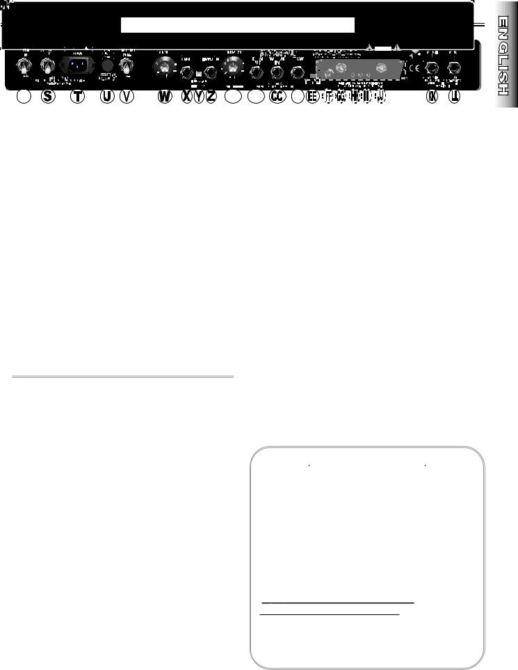
R.POWER - Switches power ON and OFF to the DD. FOOTSWITCH JACK - Connect the supplied
amplifier. (Reduce the “shock” to amplifier tubes at power-up, extending their life span, by turning the amp ON with the STAND BY switch DOWN for the first minute, then UP for normal use.
S.STAND BY - In the DOWN position, this switch puts the amp on stand by. Audio is muted and power is supplied only to the tube filaments. Use STAND BY in place of switching POWER OFF during short breaks (one hour max.). This eliminates the normal warm-up time when STAND BY is switched OFF (UP) when returning to play the amplifier and also extends the life span of your amplifier’s tubes.
T.IEC LINE CORD CONNECTOR - Connect the
supplied IEC POWER LINE CORD to a grounded AC receptacle in accordance with the voltage and frequency ratings as shown on the rear panel of the amplifier.
U.FUSE - Power Mains fuse, protects the amplifier from electrical faults. Replace a failed fuse only with the proper type and rating (See FUSE F200 under “Specifications”). If a fuse repeatedly fails, consult an authorized Fender service technician.
V.OUTPUT POWER - Selects amplifier output power:
•FULL (50 watts), or •1/4 (12.5 watts).
Note: See “Effects Loop Settings” on the next page for details on the use of items (W—AA).
W.SEND - Controls the SEND jack output level.
X.SEND JACK - Output jack for connection to the input jack of effects devices in an effects loop.
Y.LOOP - This two position button engages/bypasses the effects loop:
button OUT > to BYPASS the effects loop
button IN > to ENGAGE the effects loop
*Note: When the Footswitch is plugged into the FOOTSWITCH jack, effects LOOP BYPASS/ENGAGE are possible only from the Footswitch.
Z.RETURN JACK - Input jack for connection to the output jack of an effects device in an effects loop.
AA.RETURN - Controls the RETURN jack input level going into the power amp.
BB.PRE AMP OUT JACK - This output jack supplies an unbalanced, line-level signal (with Reverb) to a recording/sound reinforcement console, or to an external power amplifier such as another Pro-Tube amplifier used as an extension amp.
CC.POWER AMP IN - This input jack connects directly to the power amplifier, automatically disconnecting the preamp signal from the circuit. When using your Pro-Tube as an extension amp, connect the PREAMP OUT jack on another Pro-Tube amp, to this jack. Control both units from the source amplifier.
4–button Footswitch at this jack to enable these Footswitching functions:
•SELECT Pre-Amp Channel*
•BYPASS/ENGAGE the Effects Loop*
•Switch Tremolo ON/OFF
•Switch Reverb ON/OFF
*Note: When the Footswitch is plugged into the FOOTSWITCH jack, CHANNEL SELECTION and effects LOOP BYPASS/ENGAGE are possible only from
the Footswitch.
EE.—JJ. (See “Tube Adjustment” on the next page.)
KK. EXTERNAL SPEAKER JACK - Connect an 8 ohm external speaker cabinet at this jack only if another 8 ohm speaker load is connected at the MAIN SPEAKER jack (see MAIN SPEAKER jack and “Speaker Connection Guide” below).
Note: When a plug is inserted in the EXTERNAL SPEAKER jack, the amplifier is automatically switched to handle a 4 ohm speaker load.
LL. MAIN SPEAKER JACK - Keep the internal speakers connected at this jack for normal amplifier operation (8 ohm load).
IMPOR TANT !: SPEAKERS MUST ALWAYS BE CONNECTED AT THE MAIN SPEAKER JACK WHEN THE AMPLIFIER IS SWITCHED ON TO PREVENT SERIOUS DAMAGE TO THE AMPLIFIER!
Speaker Connection Guide
Connect speakers to MAIN SPKR and EXT SPKR jacks using these configurations:
MAIN |
|
EXTERNAL |
|
PROPER |
SPEAKER JACK1 |
|
SPEAKER JACK |
|
LOAD |
Internal 8 ohm |
+ |
NONE |
= |
8 ohms |
External 8 ohm |
+ |
NONE |
= |
8 ohms |
Internal 8 ohm |
+ |
External 8 ohm |
= |
4 ohms2 |
External 8 ohm |
+ |
External 8 ohm |
= |
4 ohms2 |
1
2Note: When a plug is inserted in the EXTERNAL SPEAKER jack, the amplifier is automatically switched to handle a 4 ohm speaker load.
www.fender. com 5 www.mrgearhead.net

E f f e c t s L o o p S e t t i n g s
BYPASS and ENGAGE Volume Levels
Use the SEND and RETURN level controls to normalize (make equal) the ENGAGE and BYPASS volume levels. Or, set the two levels unequal to create a preset alternate volume level, selectable from the Footswitch. Note: The alternate volume level will function with or without effects devices plugged into the loop jacks.
Setting effects loop levels.
•Turn SEND and RETURN knobs down to “1.”
•BYPASS the effects loop from the rear panel or the Footswitch.
•Connect effects device(s) to the rear panel SEND and RETURN jacks (optional for alternate volume level setting).
•Play guitar and set the amp and instrument levels as preferred. This is your bypass level.
•ENGAGE the effects loop.
•While playing guitar, turn SEND and RETURN up together* to match the bypass level set above (or to any alternate volume level). This is your engage level.
•By quickly switching between BYPASS and ENGAGE while playing, you can fine tune these settings.
*Hear unwanted distortion? Turning SEND and RETURN up at the same rate is usually a good way of setting levels quickly that will work with an external effects device. But with multiple effects devices or with devices having their own level controls, unwanted distortion may develop. Try reducing the SEND level or the level controls on individual effects devices, (increasing
RETURN or MASTER will restore the overall volume level). Listen for improvement after each change. Experiment to find the right settings.
T u b e A d j u s t m e n t
EE.V9 & V11 TROUBLE LED* - Functional only with the STAND BY switch in the UP position. This LED glows red when either the V9 or V11 tube has failed.
FF.FUSE V9 & V11 (F1)** - Protects the amplifier from damage if the V9 or V11 tube were to fail. If this fuse fails, replace the tubes in locations V9 & V11, this fuse, then set the BIAS and BALANCE.
GG.BIAS ADJUSTMENT - Trim adjustment used in conjunction with BIAS test points to set the proper tube BIAS.
HH.BIAS TEST POINTS - Test points used to measure output tube BIAS.
II.BALANCE TEST POINTS - Test points used to measure the BALANCE between power tube sections.
JJ.BALANCE ADJUSTMENT - Trim adjustment used in conjunction with the BALANCE test points to set the proper tube BALANCE.
*The TROUBLE LEDs do not indicate tube wear. Tubes may be “worn” and sound weak even when the TROUBLE LED still glows green. DO NOT WAIT FOR TUBE FAILURE TO REPLACE TUBES, (see “Tube Replacement” on the next page).
OUTPUT TUBE BIAS & BALANCE ADJUSTMENTS.
1.Warm up the Pro-Tube amp for 2 minutes with STAND BY switch DOWN and OUTPUT POWER set to FULL. Set SPEED and INTENSITY to “1“ and toggle TREMOLO
OFF. Put the STAND BY switch in the UP position.
2.Remove the bias controls cover box.
3.Set BIAS: With a DC voltmeter measure VDC between “GND” and “V9” test points while adjusting BIAS for .03 VDC (30mVDC).
4.Set BALANCE: Measure the VDC between the “V9” and “V11” test points while adjusting BALANCE for zero
(0) VDC.
5.Replace the bias controls cover box.
**Only replace a failed fuse with the proper type as indicated under “Specifications” on the next page. The fuse item F1 is used for tube failure protection. If a fuse repeatedly fails, consult with an authorized Fender service technician.
Visit Fender online at:
w w w . f e n d e r . c o m
w w w . m r g e a r h e a d . n e t
IMPORTANT
1.Make BIAS and BALANCE adjustments only when necessary. Take your Pro-Tube amp to the nearest authorized Fender Service Center if you are not sure about the settings.
2.Always set BIAS first, then BALANCE.
3.If the output tubes (6L6GC’s) cannot be BALANCED, replace the output tubes (V9 & V11), then set BIAS and BALANCE.
www.fender. com 6 www.mrgearhead.net

T u b e R e p l a c e m e n t
FIG. A
Tube life span depends upon things such as amplifier load and playing style. Power amplifier output tubes have a shorter life span than pre-amplifier tubes and usually need attention first. A simple way to check if your tubes are noticeably worn, is to replace them with a spare new set and listen for any improvement in tone quality:
ALWAYS unplug the amplifier when replacing tubes. Replace tubes ONLY with the proper type (see
“Specifications” below).
CAUTION: let tubes cool before handling, they get HOT...
1.Replace the OUTPUT tubes (V9, V11 in FIG. A) with a new set. Set BIAS and BALANCE. Listen for any improvement.
2.Keep the new OUTPUT tubes in place. Replace the PREAMPLIFIER tubes (V1, V2, V3, V4, V5, V6, V7, V8 in FIG. A) with a new set. Listen for improvement.
3.Keep the new PRE-AMPLIFIER tubes in place. Put the original OUTPUT tubes back in the amplifier. Set BIAS and BALANCE. Listen for any improvement.
If there is a noticeable improvement in sound quality after any of the 3 steps above, keep the tube arrangement that sounds the best. Obtain new spare tubes for future testing and tube replacement.
|
|
|
|
S p e c i f i c a t i o n s |
|
|
|
|
|
|
|
MODEL / TYPE |
|
|
Concert Reverb-Amp / PR 450 |
||
PART NUMBER |
|
021-5900-000 (120V, 60Hz) USA, |
|||
|
|
|
|
021-5960-000 (230V, 50Hz) Europe |
|
|
|
|
|
021-5940-000 (230V, 50Hz) UK |
|
|
|
|
|
021-5930-000 (240V, 50Hz) Aust |
|
|
|
|
|
021-5970-000 (100V, 50/60Hz) Japan |
|
POWER REQUIREMENTS |
|
325W |
|
||
POWER OUTPUT |
|
50W RMS (Full Output) |
|||
|
|
|
|
12.5W RMS (1/4 Output) |
|
|
|
|
|
1kHz sine into 8 ohms @ <5% THD, |
|
|
|
|
|
(Presence @ “1”) |
|
INPUT IMPEDANCE |
|
|
1M ohm |
|
|
TUBES |
|
Two 6L6GC (P/N 053980) |
|||
|
|
|
|
Two 12AX7A (P/N 023572) |
|
|
|
|
|
Five 12AX7WA (P/N 013341) |
|
|
|
|
|
One 12AT7 (P/N 023531) |
|
FUSES |
F200: |
F3A 250V (110V, 120V units) |
|||
|
|
|
|
T2A 250V (230V, 240V units) |
|
(Internal Filament Fuse) |
F201: |
T5A 250V (230V, 240V units) |
|||
|
|
|
F1 & F2: T100mA (all units) |
||
SPEAKERS |
|
Four Fender 10 in., 8 ohm, (P/N 048832) |
|||
FOOTSWITCH |
|
Four–Button: Channel, Loop, |
|||
|
|
|
|
Reverb, Tremolo (P/N 057025) |
|
DIMENSIONS |
Height: |
25 3/4 in. |
(65.7 cm) |
||
|
|
|
Width: |
25 3/8 in. |
(64.7 cm) |
|
|
|
Depth: |
12 27/32 in. |
(32.8 cm) |
WEIGHT |
|
85 lbs. |
(38.6 kg) |
||
Pro Reverb-Amp / PR 448
021-5500-000 (120V, 60Hz) USA
021-5560-000 (230V, 50Hz) Europe
021-5540-000 (230V, 50Hz) UK
021-5530-000 (240V, 50Hz) Aust
021-5570-000 (100V, 50/60Hz) Japan
325W
50W RMS (Full Output)
12.5W RMS (1/4 Output)
1kHz sine into 8 ohms @ <5% THD (Presence @ “1”)
1M ohm
Two 6L6GC (P/N 053980)
Two 12AX7A (P/N 023572)
Five 12AX7WA (P/N 013341)
One 12AT7 (P/N 023531)
F3A 250V (110V, 120V units)
T2A 250V (230V, 240V units)
T5A 250V (230V, 240V units)
T100mA (all units)
One Jensen 12 in., 8 ohm, (P/N 057065)
Four–Button: Channel, Loop,
Reverb, Tremolo (P/N 057025)
17 3/8 in. |
(44.3 cm) |
25 3/8 in. |
(64.7 cm) |
12 27/32 in. |
(32.8 cm) |
75 lbs. |
(34 kg) |
Product specifications are subject to change without notice.
www.fender. com 7 www.mrgearhead.net
P r o R e v e r b - A m p • C o n c e r t R e v e r b - A m p
Enhorabuena. El amplificador Fender® Pro-Tube Series le permite obtener sonidos de primera calidad y le proporciona una gran versatilidad. En este manual se tratan aspectos relacionados con el funcionamiento y el mantenimiento de los amplificadores Pro Reverb–Amp y Concert Reverb–Amp que, aunque admiten distintas configuraciones de altavoz, comparten las mismas características profesionales:
àDos canales de preamplificador: •Controles de VOLUMEN, AGUDOS, MEDIOS y GRAVES independientes, •Canal 1— Conmutador BRIGHT para la acentuación de sonidos nítidos,
•Canal 2—Control GAIN para la cálida distorsión de Pro-Tube.
àHerramientas de tono: •La agradable reverberación Spring REVERB de Fender, •la definición de frecuencias ultra altas a través del control de presencia PRESENCE, •la modulación de volumen del efecto TREMOLO a través de los controles de velocidad e intensidad SPEED e INTENSITY.
àOpciones de bucle de efectos: •Los controles de salida y entrada SEND y RETURN permiten normalizar los niveles de volumen entre los valores ENGAGE/BYPASS o establecer niveles de volumen alternativos.
àFunciones remotas: Conmutador de pedal Footswitch (incluido) de 4 botones para activar o desactivar: •la selección de canal
CHANNEL SELECTION, •el bucle de efectos EFFECTS LOOP,
•el efecto REVERB y •el efecto TREMOLO.
àOpciones de expansión: •Salida para un segundo amplificador Pro-Tube mediante los conectores PRE-AMP OUT y POWERAMP IN, lo que permite controlar ambas unidades como si fueran una, •Salida para equipos de refuerzo de sonido,
•Posibilidad de conectar dos cajas de altavoces de 16 ohmios a cada uno de los amplificadores Pro-Tube a través de los conectores MAIN SPEAKER y EXTERNAL SPEAKER.
àNiveles de salida seleccionables: •POTENCIA MÁXIMA, que proporciona 50 vatios. •1/4 de POTENCIA DE SALIDA, que proporciona 12,5 vatios, lo que resulta idóneo para recintos de reducidas dimensiones. También se puede utilizar para obtener el sonido característico de los valores de nivel máximo a niveles de volumen bajos.
àCalidad: •Chasis fabricado con componentes de máxima calidad. •Cajas contrachapadas con capas de abedul/arce de 3/4 pulgadas (1,9 cm). •Baño de Tolex® para dar un aspecto flamante y duradero.
àExtras: Patillas inclinables para poder escuchar el sonido desde un ángulo distinto.
àEn este manual también se describen los procedimientos de prueba, balance y sustitución de los tubos de vacío del amplificador, que constituyen la base del sonido Pro-Tube.
P a n e l f r o n t a l
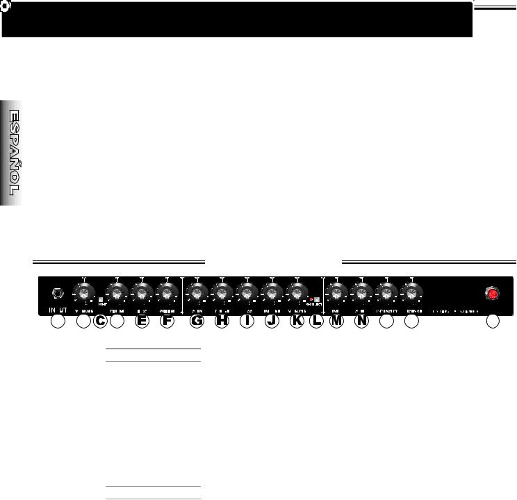
A.INPUT: Conector de entrada para guitarras.
1•Canal•1
B.VOLUME: Ajusta el volumen total del amplificador cuando el canal-1 está activo.
C.BRIGHT: Este botón de dos posiciones permite aumentar los agudos del canal -1 en función de la
posición del botón:
hacia FUERA > para desactivar el efecto BRIGHT
hacia DENTRO > para activar el efecto BRIGHT
D.TREBLE: Controla el nivel de frecuencias altas del canal-1.
E.BASS: Controla el nivel de frecuencias bajas del canal-1.
F.MIDDLE: Controla el nivel de frecuencias medias del canal-1.
2•Canal•2
G.GAIN: Controla el nivel de distorsión del preamplificador cuando el canal-2 está activo. Cuanto
mayor es el nivel de ganancia GAIN, mayor es la distorsión. Utilice el control de ganancia GAIN junto con el control de volumen VOLUME del canal 2 (K) para establecer el volumen global del amplificador.
H.TREBLE: Controla el nivel de frecuencias altas del canal-2. El efecto del control de agudos TREBLE es menor cuando el valor del control de medios MIDDLE es superior a “3”.
I.BASS: Controla el nivel de frecuencias bajas del canal-2.
J.MIDDLE: Controla el nivel de frecuencias medias del canal-2.
K.VOLUME: Ajusta, junto con el control de ganancia
GAIN (G), el volumen total del amplificador cuando el canal-2 está activo. Utilice el control de volumen VOLUME para establecer el nivel de salida del canal-2 de acuerdo con el nivel del canal-1.
L.CHANNEL SELECT: Este botón de dos posiciones selecciona el canal del amplificador. El indicador LED mostrará el canal seleccionado:
hacia FUERA > para Canal-1 > LED APAGADO hacia DENTRO > para Canal-2 > LED ENCENDIDO
Nota: Cuando el conmutador de pedal se encuentra conectado, la función de selección de canal CHANNEL SELECT se transfiere al conmutador de pedal y se desactiva en el panel frontal.
M.REVERB: Controla el nivel de reverberación REVERB de ambos canales. Nota: El efecto REVERB se puede activar/desactivar desde el conmutador de pedal cuando éste se encuentra conectado.
N.SPEED: Controla la velocidad de modulación del efecto
TREMOLO. Nota: El conmutador de pedal debe estar conectado (y el botón TREMOLO activado) para que el efecto TREMOLO funcione. Active el control de intensidad INTENSITY para una mejor apreciación de los valores del control de velocidad SPEED.
O.INTENSITY: Controla la profundidad de barrido del efecto
TREMOLO. Nota: El conmutador de pedal debe estar conectado (y el botón TREMOLO activado) para que el efecto TREMOLO funcione. El efecto TREMOLO es menos intenso en el modo de 1/4 de potencia.
P.PRESENCE: Controla el nivel de frecuencias ultra altas de los canales 1 y 2.
Q.POWER INDICATOR (Indicador de corriente): Se ilumina cuando el interruptor de encendido POWER está activado y el amplificador Pro-Tube recibe alimentación.
Nota: Para sustituir la bombilla, desenrosque la cubierta roja. Utilice bombillas del tipo T47.
www.fender. com 8 www.mrgearhead.net
F e n d e r ® P r o - T u b e S e r i e s
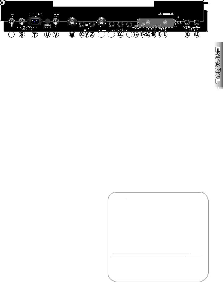
R.POWER (Interruptor de encendido): Hacia
ARRIBA, este interruptor ENCENDERÁ la unidad; hacia ABAJO, este interruptor APAGARÁ la unidad. (Para reducir el impacto que el encendido puede tener sobre los tubos del amplificador y prolongar la duración de los mismos, encienda el amplificador con el conmutador de espera STAND BY hacia ABAJO durante un minuto.
S.STAND BY: Hacia ABAJO, este conmutador establece el amplificador en el modo de espera STAND BY. Utilice el conmutador de espera STAND BY en vez del interruptor de encendido POWER para APAGAR el amplificador durante periodos de descanso (una hora como máximo). De este modo, se elimina el tiempo de calentamiento normal de los tubos y se prolonga la vida de los mismos.
T.IEC LINE CORD CONNECTOR (Conector de cable
de línea IEC): Conecte el cable de ALIMENTACIÓN IEC a una toma de corriente de CA de acuerdo con las especificaciones de voltaje y frecuencia indicadas en el panel posterior de la unidad.
U.FUSE: Protege la unidad de fallos eléctricos. Para sustituir un fusible, utilice otro del mismo tipo y potencia (Consulte FUSIBLE F200 en la sección “Especificaciones”). En caso de que los fusibles se fundan con frecuencia, póngase en contacto con un centro de servicio Fender autorizado.
V.OUTPUT POWER: Permite seleccionar la potencia de salida. Hacia ARRIBA para obtener una potencia de salida 50 vatios, hacia ABAJO para obtener una potencia de salida de 12,5 vatios.
W.SEND: Controla el nivel de salida del conector de salida
SEND.
X.SEND JACK: Conector de salida para la conexión de un dispositivo de efectos en un bucle de efectos.
Y.LOOP: Este botón de dos posiciones activa o desactiva el bucle de efectos en función de la posición del botón:
hacia FUERA > para desactivar (BYPASS ) el bucle de efectos
hacia DENTRO > para activar (ENGAGE ) el bucle de efectos
Nota: Cuando el conmutador de pedal se encuentra conectado, la función de activación o desactivación del bucle LOOP se transfiere al conmutador de pedal y se desactiva en el panel posterior.
Z.RETURN JACK: Conector de entrada para la conexión de un dispositivo de efectos en un bucle de efectos.
AA.RETURN: Controla el nivel de entrada INPUT de la entrada del bucle de efectos EFFECTS LOOP en el amplificador principal. (Consulte “Configuración del bucle de efectos” en la página siguiente).
BB.PRE AMP OUT: Conector de salida que transmite una señal de nivel de línea sin balance (con efecto REVERB) a consolas de grabación o de refuerzo de sonido o a un amplificador externo como, por ejemplo, otro amplificador Pro-Tube utilizado como amplificador de extensión.
CC.POWER AMP IN: Conector de entrada que se conecta directamente al amplificador principal y que elimina de forma automática la señal del preamplificador del circuito.
Cada vez que utilice Twin como amplificador de extensión, conecte la salida de amplificador PRE-AMP OUT de otro Pro-Tube a este conector. De este modo, podrá controlar ambas unidades desde el amplificador origen.
DD.FOOTSWITCH: Conecte el conmutador de pedal de 4 botones que se facilita a este conector para activar las siguientes funciones desde el conmutador de pedal:
•SELECCIONAR canal-1/canal-2*
•ACTIVAR/DESACTIVAR (BYPASS/ENGAGE) el bucle de efectos*
•Activar/Desactivar el efecto TREMOLO
•Activar/Desactivar el efecto REVERB
*Tanto la selección de canal como los valores bypass/engage del bucle de efectos se transferirán al conmutador de pedal al conectarlo (los interruptores del panel se desactivarán).
EE.—JJ. (Consulte AJUSTE DE LOS TUBOS en la página siguiente).
KK.EXTERNAL SPEAKER: Conecte un altavoz externo de 8 ohmios a este conector únicamente si existe otro altavoz conectado de 8 ohmios al conector MAIN SPEAKER (si desea obtener más información, consulte MAIN SPEAKER (Altavoz principal) y GUÍA DE CONEXIÓN DE LOS ALTAVOCES a continuación).
Nota: Si se utiliza el CONECTOR DE ALTAVOZ EXTERNO, el amplificador cambiará AUTOMÁTICAMENTE para aceptar una carga de altavoces de 4 ohmios.
LL.MAIN SPEAKER: Para un funcionamiento normal del
amplificador (carga de 8 ohmios), conecte los altavoces internos a este conector. IMPORTANTE: MIENTRAS LA UNIDAD ESTÉ ENCENDIDA, LOS ALTAVOCES DEBERÁN ESTAR SIEMPRE CONECTADOS AQUÍ PARA EVITAR QUE SE PRODUZCAN DAÑOS IMPORTANTES EN LA UNIDAD.
Configuraciones recomendadas para los altavoces:
Guía de conexión de los altavoces
Los conectores MAIN SPKR y EXT SPKR recomendada con altavoces conectados de las formas siguientes:
CONECTOR1 |
|
CONECTOR |
|
CARGA |
MAIN SPEAKER |
|
EXTERNAL SPEAKER |
|
TOTAL |
Interno 8 ohmios |
+ |
NINGUNO |
= |
8 ohmios |
Externo 8 ohmios |
+ |
NINGUNO |
= |
8 ohmios |
Interno 8 ohmios |
+ |
Externo 8 ohmios |
= |
4 ohmios2 |
Externo 8 ohmios |
+ |
Externo 8 ohmios |
= |
4 ohmios2 |
1
2Si se utiliza el CONECTOR DE ALTAVOZ EXTERNO, el amplificador cambiará AUTOMÁTICAMENTE para aceptar una carga de altavoces de 4 ohmios.
www.fender. com 9 www.mrgearhead.net
 Loading...