

Page 1

GE Fanuc Automation
Computer Numerical Control Products
Series 15 / 150 – Model B
Macro Compiler/Executer
Programming Manual
GFZ-62073E-2/03 September 1995
Page 2

Warnings, Cautions, and Notes
as Used in this Publication
Warning notices are used in this publication to emphasize that hazardous voltages, currents,
temperatures, or other conditions that could cause personal injury exist in this equipment or
may be associated with its use.
In situations where inattention could cause either personal injury or damage to equipment, a
Warning notice is used.
Caution notices are used where equipment might be damaged if care is not taken.
GFL-001
Warning
Caution
Note
Notes merely call attention to information that is especially significant to understanding and
operating the equipment.
This document is based on information available at the time of its publication. While efforts
have been made to be accurate, the information contained herein does not purport to cover all
details or variations in hardware or software, nor to provide for every possible contingency in
connection with installation, operation, or maintenance. Features may be described herein
which are not present in all hardware and software systems. GE Fanuc Automation assumes
no obligation of notice to holders of this document with respect to changes subsequently made.
GE Fanuc Automation makes no representation or warranty, expressed, implied, or statutory
with respect to, and assumes no responsibility for the accuracy, completeness, sufficiency, or
usefulness of the information contained herein. No warranties of merchantability or fitness for
purpose shall apply.
©Copyright 1995 GE Fanuc Automation North America, Inc.
All Rights Reserved.
Page 3

B–62073E–2/03
Table of contents
PROGRAMMING
1. GENERAL 3. . . . . . . . . . . . . . . . . . . . . . . . . . . . . . . . . . . . . . . . . . . . . . . . . . . . . . . . . . . .
1.1 OUTLINE 3. . . . . . . . . . . . . . . . . . . . . . . . . . . . . . . . . . . . . . . . . . . . . . . . . . . . . . . . . . . . . . . . . . . . . . .
1.2 FEATURES 5. . . . . . . . . . . . . . . . . . . . . . . . . . . . . . . . . . . . . . . . . . . . . . . . . . . . . . . . . . . . . . . . . . . . . .
2. MACRO COMPILER 6. . . . . . . . . . . . . . . . . . . . . . . . . . . . . . . . . . . . . . . . . . . . . . . . . . .
2.1 OUTLINE 6. . . . . . . . . . . . . . . . . . . . . . . . . . . . . . . . . . . . . . . . . . . . . . . . . . . . . . . . . . . . . . . . . . . . . . .
2.2 FLOW FOR CREATING, REGISTERING AND SAVING PROGRAMS 7. . . . . . . . . . . . . . . . . . . . .
2.3 USE OF MACRO COMPILER 8. . . . . . . . . . . . . . . . . . . . . . . . . . . . . . . . . . . . . . . . . . . . . . . . . . . . . .
2.3.1 Registering a P–CODE Program in F–ROM Using a Memory Card
2.3.2 Registering the P–CODE Program in F–ROM Using a ROM Cassette
2.3.3 Compiling and Registering Custom Macro Programs in F–ROM Using the Series 15–B 19. . . . . . . . . .
2.3.4 P–CODE Program 23. . . . . . . . . . . . . . . . . . . . . . . . . . . . . . . . . . . . . . . . . . . . . . . . . . . . . . . . . . . . . . . . .
2.3.5 F–ROM 25. . . . . . . . . . . . . . . . . . . . . . . . . . . . . . . . . . . . . . . . . . . . . . . . . . . . . . . . . . . . . . . . . . . . . . . . .
2.4 COMPILE PARAMETER 27. . . . . . . . . . . . . . . . . . . . . . . . . . . . . . . . . . . . . . . . . . . . . . . . . . . . . . . . . .
2.5 ERROR CODE LIST 36. . . . . . . . . . . . . . . . . . . . . . . . . . . . . . . . . . . . . . . . . . . . . . . . . . . . . . . . . . . . . .
(When Compiled with a Personal Computer) 8. . . . . . . . . . . . . . . . . . . . . . . . . . . . . . . . . . . . . . . . . . . .
(When the P–CODE Program has been Compiled with the System P or a Personal Computer) 14. . . . .
3. EXECUTION MACRO 39. . . . . . . . . . . . . . . . . . . . . . . . . . . . . . . . . . . . . . . . . . . . . . . . . .
3.1 INTERFACE WITH USER PROGRAM AND
EXECUTION MACRO IN P–CODE PROGRAM 39. . . . . . . . . . . . . . . . . . . . . . . . . . . . . . . . . . . . . . .
3.1.1 Call Code and Program No. 39. . . . . . . . . . . . . . . . . . . . . . . . . . . . . . . . . . . . . . . . . . . . . . . . . . . . . . . . . .
3.1.2 Variables 43. . . . . . . . . . . . . . . . . . . . . . . . . . . . . . . . . . . . . . . . . . . . . . . . . . . . . . . . . . . . . . . . . . . . . . . .
3.1.3 Argument Designation 43. . . . . . . . . . . . . . . . . . . . . . . . . . . . . . . . . . . . . . . . . . . . . . . . . . . . . . . . . . . . . .
3.2 LIMITATION FOR EXECUTION MACRO 44. . . . . . . . . . . . . . . . . . . . . . . . . . . . . . . . . . . . . . . . . . . .
3.2.1 Argument Specification 44. . . . . . . . . . . . . . . . . . . . . . . . . . . . . . . . . . . . . . . . . . . . . . . . . . . . . . . . . . . . .
3.2.2 Macro call 44. . . . . . . . . . . . . . . . . . . . . . . . . . . . . . . . . . . . . . . . . . . . . . . . . . . . . . . . . . . . . . . . . . . . . . .
3.2.3 Variable 44. . . . . . . . . . . . . . . . . . . . . . . . . . . . . . . . . . . . . . . . . . . . . . . . . . . . . . . . . . . . . . . . . . . . . . . . .
3.2.4 Custom Macro Commands 44. . . . . . . . . . . . . . . . . . . . . . . . . . . . . . . . . . . . . . . . . . . . . . . . . . . . . . . . . .
3.2.5 NC Commands Which Cannot be Used in Automatic Operation 44. . . . . . . . . . . . . . . . . . . . . . . . . . . . .
3.2.6 Modal Call from Execution Macro 44. . . . . . . . . . . . . . . . . . . . . . . . . . . . . . . . . . . . . . . . . . . . . . . . . . . .
3.2.7 Calling a P–CODE Program from an Execution Macro Using the G, M, S, T, or B User Code 45. . . . . .
3.2.8 Calling a User Program Using an Execution Macro 45. . . . . . . . . . . . . . . . . . . . . . . . . . . . . . . . . . . . . . .
3.2.9 Specifying of the G Code for Macro Calls of P–CODE Programs 45. . . . . . . . . . . . . . . . . . . . . . . . . . . .
3.2.10 Calling a Macro Using a T Code 46. . . . . . . . . . . . . . . . . . . . . . . . . . . . . . . . . . . . . . . . . . . . . . . . . . . . . .
3.2.11 Macro and Subprogram Multiplexity in Execution Macro 47. . . . . . . . . . . . . . . . . . . . . . . . . . . . . . . . . .
3.3 DISPLAYING AND SETTING VARIABLES 48. . . . . . . . . . . . . . . . . . . . . . . . . . . . . . . . . . . . . . . . . .
3.3.1 User Program Common Variables (#100–#199, #500–#999) 48. . . . . . . . . . . . . . . . . . . . . . . . . . . . . . . .
3.3.2 P–CODE Program Common Variable (#100–#199, #500–#999) 48. . . . . . . . . . . . . . . . . . . . . . . . . . . . .
3.3.3 P–CODE Program Local Variable (#1–#33) 48. . . . . . . . . . . . . . . . . . . . . . . . . . . . . . . . . . . . . . . . . . . . .
3.3.4 Variable Name Setting (SETVN) 48. . . . . . . . . . . . . . . . . . . . . . . . . . . . . . . . . . . . . . . . . . . . . . . . . . . . .
3.4 CAUTIONS 49. . . . . . . . . . . . . . . . . . . . . . . . . . . . . . . . . . . . . . . . . . . . . . . . . . . . . . . . . . . . . . . . . . . . .
4. CONVERSATIONAL MACRO FUNCTION 50. . . . . . . . . . . . . . . . . . . . . . . . . . . . . . . . .
4.1 OVER VIEW 50. . . . . . . . . . . . . . . . . . . . . . . . . . . . . . . . . . . . . . . . . . . . . . . . . . . . . . . . . . . . . . . . . . . . .
4.2 CONVERSATIONAL MACRO FUNCTION 52. . . . . . . . . . . . . . . . . . . . . . . . . . . . . . . . . . . . . . . . . . .
4.3 AUXILIARY MACRO FUNCTION 54. . . . . . . . . . . . . . . . . . . . . . . . . . . . . . . . . . . . . . . . . . . . . . . . . .
4.4 COORDINATE SYSTEM SCREEN 56. . . . . . . . . . . . . . . . . . . . . . . . . . . . . . . . . . . . . . . . . . . . . . . . . .
4.4.1 Character Coordinate System 56. . . . . . . . . . . . . . . . . . . . . . . . . . . . . . . . . . . . . . . . . . . . . . . . . . . . . . . .
i
Page 4

Table of contents
4.4.2 Graphic Coordinate System 57. . . . . . . . . . . . . . . . . . . . . . . . . . . . . . . . . . . . . . . . . . . . . . . . . . . . . . . . . .
B–62073E–2/03
4.5 VARIABLE, FUNCTION AND CONTROL CODE 58. . . . . . . . . . . . . . . . . . . . . . . . . . . . . . . . . . . . . .
4.5.1 System Variable 61. . . . . . . . . . . . . . . . . . . . . . . . . . . . . . . . . . . . . . . . . . . . . . . . . . . . . . . . . . . . . . . . . . .
4.5.2 P–CODE Program Exclusive Local Variables 61. . . . . . . . . . . . . . . . . . . . . . . . . . . . . . . . . . . . . . . . . . . .
4.5.3 Conversational Macro P–CODE Common Variables 61. . . . . . . . . . . . . . . . . . . . . . . . . . . . . . . . . . . . . .
4.5.4 UI and UO Signal Separation for User and P–CODE Programs 62. . . . . . . . . . . . . . . . . . . . . . . . . . . . . .
4.5.5 Conversational Macro Special Variables (#30000–) 63. . . . . . . . . . . . . . . . . . . . . . . . . . . . . . . . . . . . . . .
4.5.6 Expanded Conversational Macro Exclusive Variable (#40000 –) 64. . . . . . . . . . . . . . . . . . . . . . . . . . . . .
4.5.7 Reference and Writing System Common Variables 65. . . . . . . . . . . . . . . . . . . . . . . . . . . . . . . . . . . . . . .
4.5.8 Execution Control Variable 65. . . . . . . . . . . . . . . . . . . . . . . . . . . . . . . . . . . . . . . . . . . . . . . . . . . . . . . . . .
4.5.9 Key Input Control Variable 66. . . . . . . . . . . . . . . . . . . . . . . . . . . . . . . . . . . . . . . . . . . . . . . . . . . . . . . . . .
4.5.10 Character String Registered Program Control Variable #8509 68. . . . . . . . . . . . . . . . . . . . . . . . . . . . . . .
4.5.11 Arrangement Type Processing of Conversational Macro Exclusive Variable 69. . . . . . . . . . . . . . . . . . . .
4.5.12 Reference of Arrangement of Conversational Macro Exclusive Variables 70. . . . . . . . . . . . . . . . . . . . . .
4.5.13 Refer to and Read CNC Program with Conversation Macro 71. . . . . . . . . . . . . . . . . . . . . . . . . . . . . . . .
4.5.14 Reading of Cutting Time and Cutting Distance by Conver–Sational Macro, and Preset Functions 79. . .
4.5.15 PMC Axis Control by Conversational Macro 79. . . . . . . . . . . . . . . . . . . . . . . . . . . . . . . . . . . . . . . . . . . .
4.5.16 Torque Limit Override Control 82. . . . . . . . . . . . . . . . . . . . . . . . . . . . . . . . . . . . . . . . . . . . . . . . . . . . . . .
4.5.17 A/D Converter Data Reading by Conversational Macro 84. . . . . . . . . . . . . . . . . . . . . . . . . . . . . . . . . . . .
4.5.18 Conversational Macro Variable Window Function 86. . . . . . . . . . . . . . . . . . . . . . . . . . . . . . . . . . . . . . . .
4.5.19 Reading Relative Coordinates by Conversational Macro, and Preset 96. . . . . . . . . . . . . . . . . . . . . . . . . .
4.5.20 Address Function 97. . . . . . . . . . . . . . . . . . . . . . . . . . . . . . . . . . . . . . . . . . . . . . . . . . . . . . . . . . . . . . . . . .
4.5.21 Screen Display Control Codes 98. . . . . . . . . . . . . . . . . . . . . . . . . . . . . . . . . . . . . . . . . . . . . . . . . . . . . . . .
4.5.22 Execution Control Code 105. . . . . . . . . . . . . . . . . . . . . . . . . . . . . . . . . . . . . . . . . . . . . . . . . . . . . . . . . . . .
4.5.23 RS–232–C Control by Conversational Macro 106. . . . . . . . . . . . . . . . . . . . . . . . . . . . . . . . . . . . . . . . . . . .
4.5.24 File Control 115. . . . . . . . . . . . . . . . . . . . . . . . . . . . . . . . . . . . . . . . . . . . . . . . . . . . . . . . . . . . . . . . . . . . . .
4.5.25 Functions of PMC Address 121. . . . . . . . . . . . . . . . . . . . . . . . . . . . . . . . . . . . . . . . . . . . . . . . . . . . . . . . . .
4.5.26 PMC Address Control Code (G310) 122. . . . . . . . . . . . . . . . . . . . . . . . . . . . . . . . . . . . . . . . . . . . . . . . . . .
4.5.27 Variable for Reading Remaining Shift Amount 123. . . . . . . . . . . . . . . . . . . . . . . . . . . . . . . . . . . . . . . . . .
4.5.28 Referring to NC Parameter 124. . . . . . . . . . . . . . . . . . . . . . . . . . . . . . . . . . . . . . . . . . . . . . . . . . . . . . . . . .
4.6 CONVERSATIONAL MACRO DEBUG FUNCTION 125. . . . . . . . . . . . . . . . . . . . . . . . . . . . . . . . . . . .
4.6.1 Overview 125. . . . . . . . . . . . . . . . . . . . . . . . . . . . . . . . . . . . . . . . . . . . . . . . . . . . . . . . . . . . . . . . . . . . . . . .
4.6.2 Displaying Macro Variables 125. . . . . . . . . . . . . . . . . . . . . . . . . . . . . . . . . . . . . . . . . . . . . . . . . . . . . . . . .
4.6.3 Conversational Macro Debugger Function 125. . . . . . . . . . . . . . . . . . . . . . . . . . . . . . . . . . . . . . . . . . . . . .
5. PARAMETER 128. . . . . . . . . . . . . . . . . . . . . . . . . . . . . . . . . . . . . . . . . . . . . . . . . . . . . . . . . .
APPENDIX
A. Macro Program Example 131. . . . . . . . . . . . . . . . . . . . . . . . . . . . . . . . . . . . . . . . . . . . . . .
A.1 DESCRIPTION OF PROGRAMS 132. . . . . . . . . . . . . . . . . . . . . . . . . . . . . . . . . . . . . . . . . . . . . . . . . . . .
A.2 DESCRIPTION OF MACRO VARIABLES 133. . . . . . . . . . . . . . . . . . . . . . . . . . . . . . . . . . . . . . . . . . . .
A.3 SOURCE PROGRAM 134. . . . . . . . . . . . . . . . . . . . . . . . . . . . . . . . . . . . . . . . . . . . . . . . . . . . . . . . . . . . .
A.4 FLOW CHART 139. . . . . . . . . . . . . . . . . . . . . . . . . . . . . . . . . . . . . . . . . . . . . . . . . . . . . . . . . . . . . . . . . . .
A.5 PROGRAM EXPLANATION 143. . . . . . . . . . . . . . . . . . . . . . . . . . . . . . . . . . . . . . . . . . . . . . . . . . . . . . .
A.6 PROGRAM DESCRIPTION 146. . . . . . . . . . . . . . . . . . . . . . . . . . . . . . . . . . . . . . . . . . . . . . . . . . . . . . . .
A.7 LIST OF KANJI AND HIRAGANA CODES 151. . . . . . . . . . . . . . . . . . . . . . . . . . . . . . . . . . . . . . . . . . .
A.8 MACRO EXECUTOR FUNCTIONS 159. . . . . . . . . . . . . . . . . . . . . . . . . . . . . . . . . . . . . . . . . . . . . . . . .
ii
Page 5

PROGRAMMING
Page 6
B–62073E–2/03
1
GENERAL
1.GENERAL
1.1
OUTLINE
NC programs include those which are prepared by custom macro and very
seldom altered and those which may differ from one another according to
relevant machining such as part programs. This function is that which converts
the created custom macro program to execu–
at the machine tool builder and executes it. Further, the conversational
macro can also be executed independently in parallel with a normal NC
program by means of converting the conversational macro program to
execution format (P–CODE program).
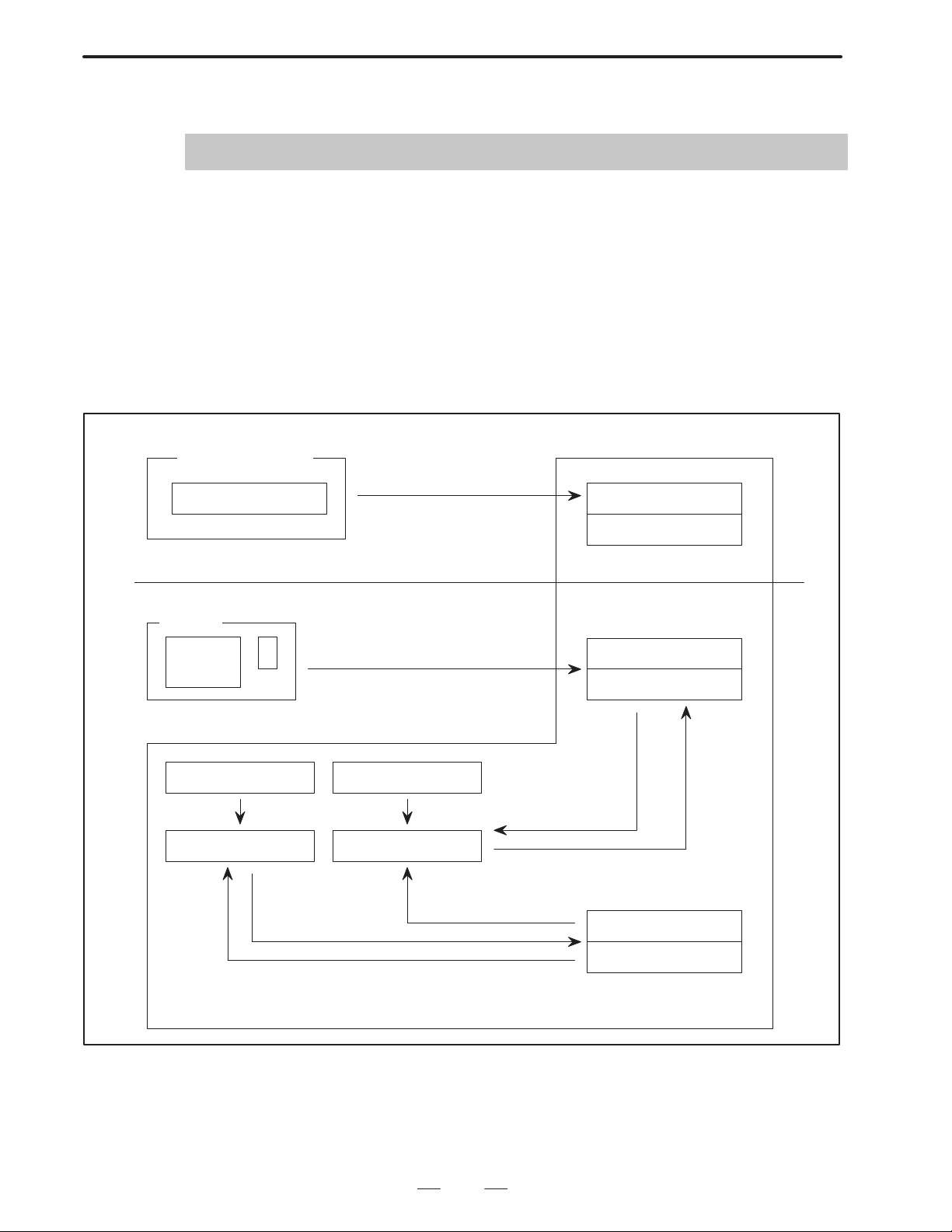
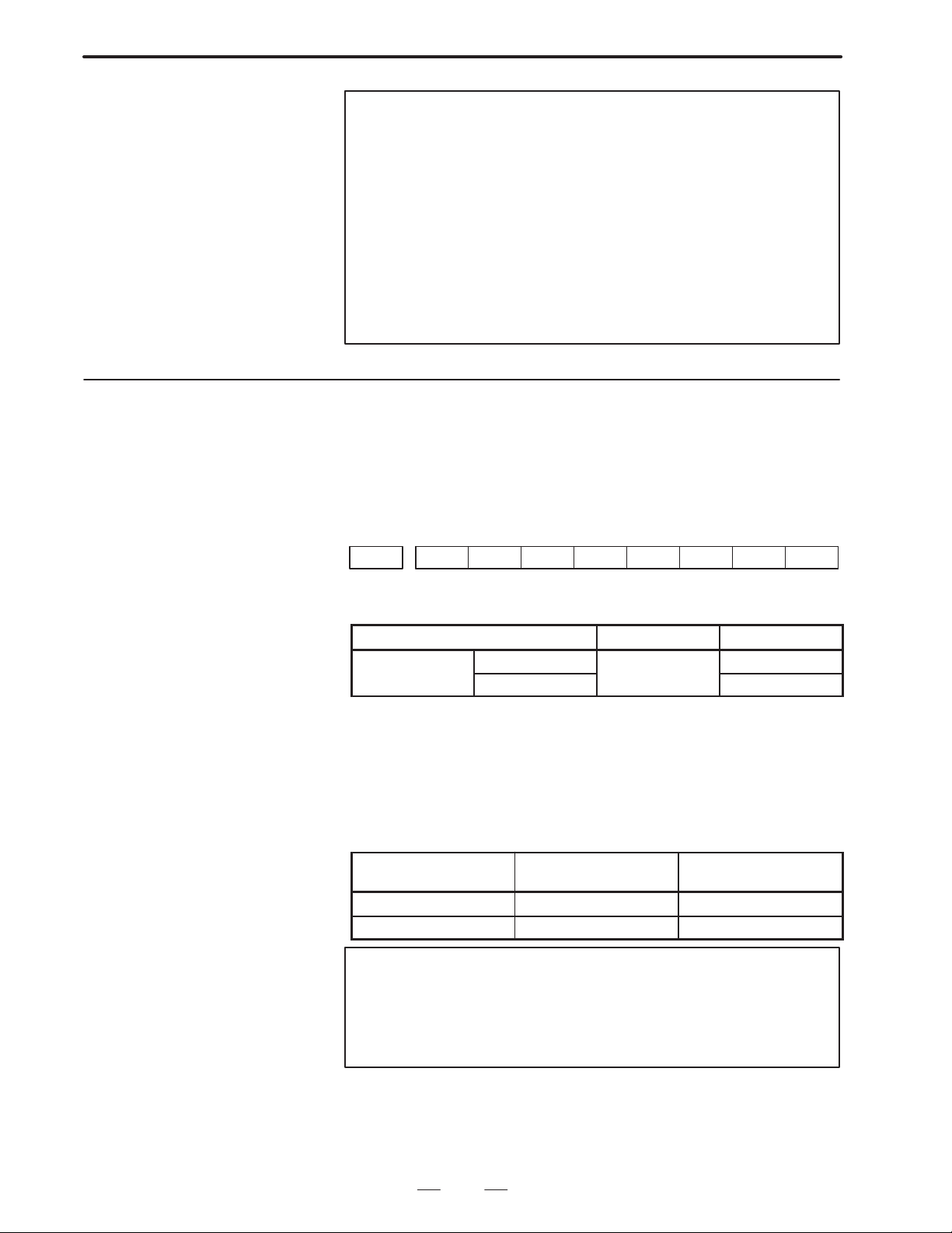
Macro compiler basic outline diagram
Part program strage
User program Execution macro
(Memory operation execution level)
CRT/MDI
M/T/G code call
Software key call
tion format (P–CODE program)
executer
Conversational macro
executer
Parameter 8537 Parameter 8536
(when switching on power)
Control variable #8600 Control variable #8500
Startup by
system variable
Program number change
Program number change
Program
number
change
Auxiliary macro
executer
Startup
by system
variable
3
Page 7
1. GENERAL
Series 15B
B–62073E–2/03
The words used in the explanation are defined as follows.
“P–CODE program” –––––
Execution type macroprogram prepared by machine tool builders,
being compiled and registered to ROM.
“Execution macro” –––
Program to operate machine in P–CODE program.
“Conversational macro” –––
Program operated screen in P–CODE program.
“User program” –––––
Program prepared by end–user for program edit memory.
This manual describes the following products.
Model name Abbreviation
FANUC Series 15–TB 15–TB
FANUC Series 15–MB 15–MB
4
Page 8

B–62073E–2/03
1.GENERAL
1.2
FEATURES
(1) Since the custom macro is converted into an execution format and
registered, the execution speed is high. This will shorten the
machining time and improve the machining accuracy.
(2) The registration to the ROM eliminates prevents custom macro
damage through misoperation. This will improve the reliability.
(3) Since the converted program into execution format is not indicated
on the program display, the machine tool builder’s knowhow can be
protected.
(4) Since the execution format program is registered in the ROM, the
program edit memory can effectively be used.
(5 ) The user can call the execution format program (P–CODE program)
with an easy call procedure without being conscious of the registered
program.
(6) Using the conversational function and conversational macro,
execution can be performed.
(7) There is an auxiliary macro for executing regardless of the selected
mode and screen.
(8) Compiling the NC program, and ROM output can be performed by
the Series 15 itself.
(9) When compiled in Series 15, without writing the execution format
program to ROM, it can be started up as it is and execution/debug can
be performed.
5
Page 9
2. MACRO COMPILER
MACRO COMPILER
2
B–62073E–2/03
2.1
OUTLINE
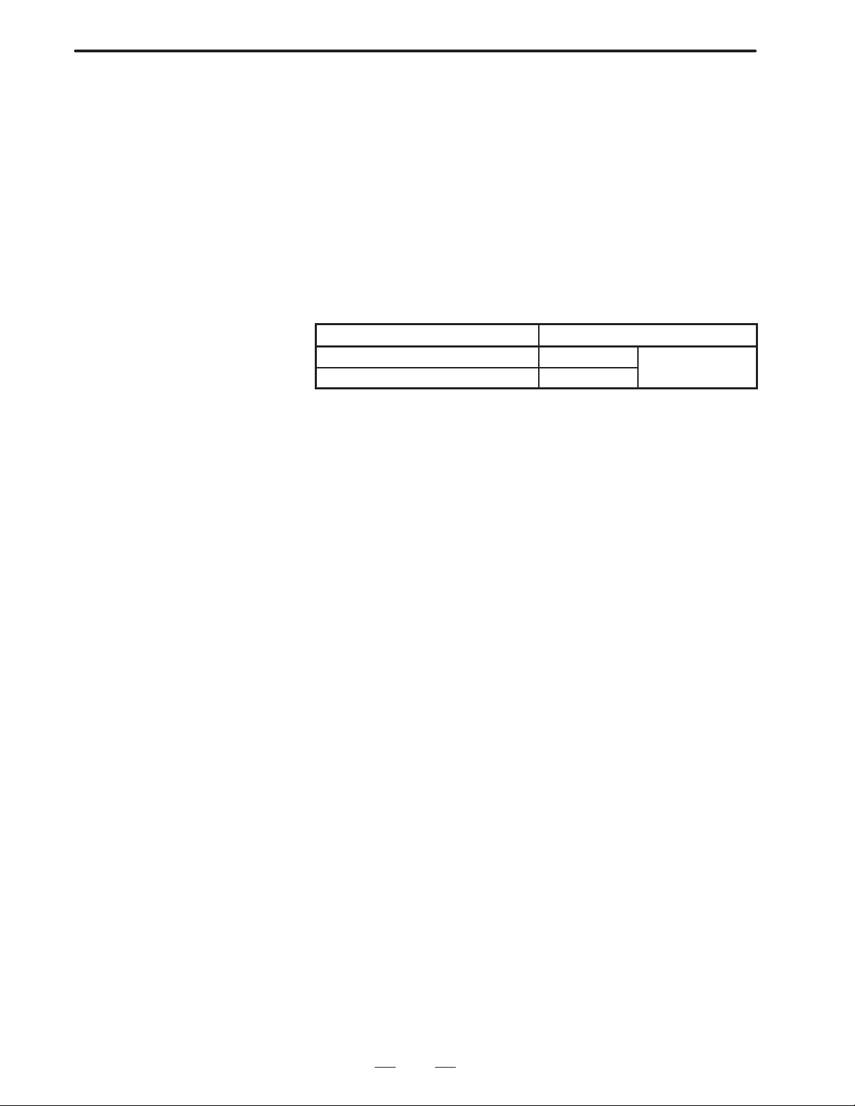
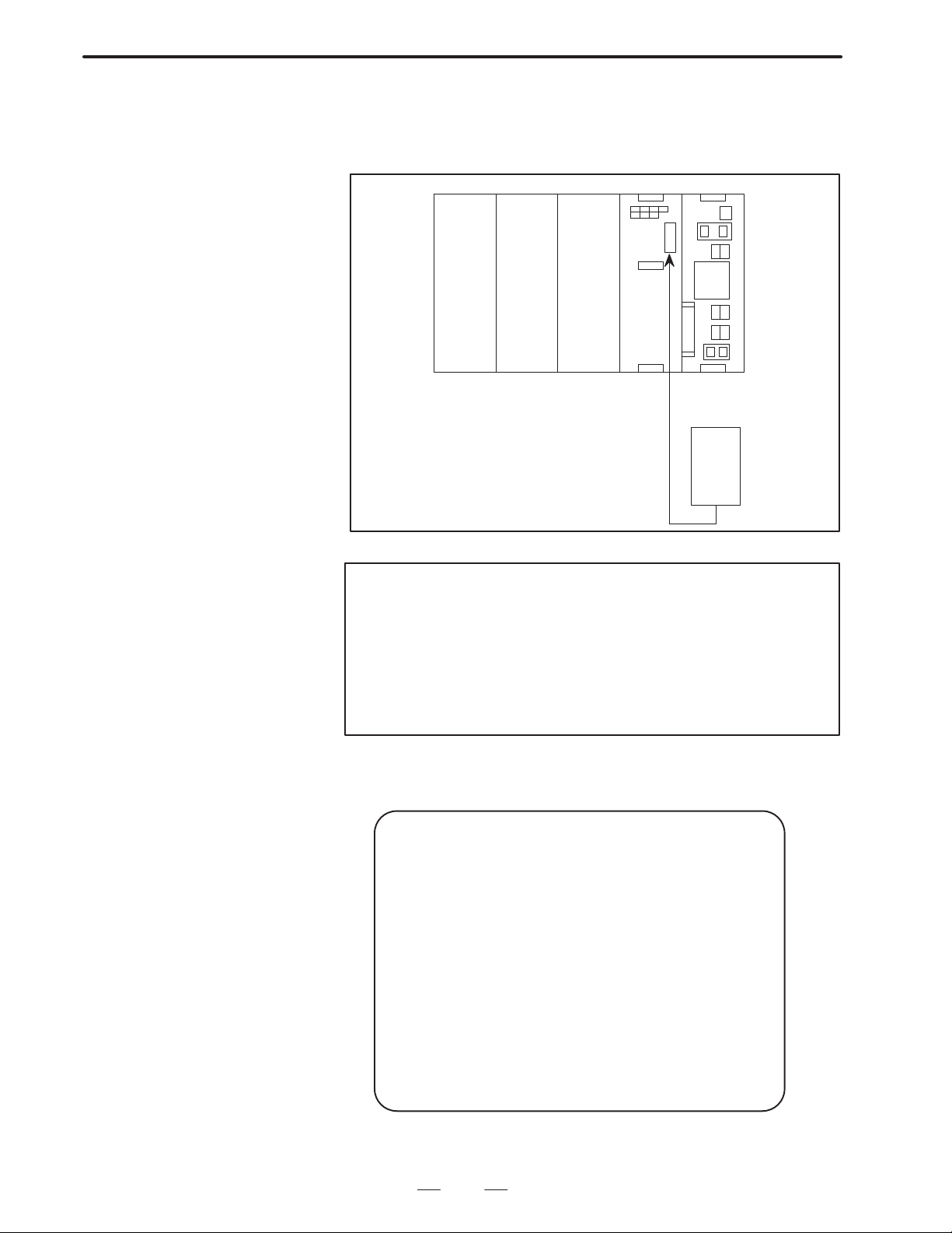
A custom macro program is converted to executable form (hereafter
called a P–CODE programs), then registered in flash ROM (hereafter
called F–ROM). The registered P–CODE program can be called from the
user programs and executed by using the G, M or T code (execution
Macro) or by setting the program number in the associated parameter
(conversational macro execution).
Custom macro programs
O9000 ;
#1=#2+#5 ;
:
:
M99 ;
Macro compiler (FANUC System P)
(Personal computer)
(FANUC Series 15–B)
Compile parameters
8500=10000001
8501=00000001
:
:
:
8550=50
Set parametersRegister programs
Compile
P–CODE programs and executer
Write to ROM
F–ROM
Note
The executer executes the P–CODE program generated by
compiling a custom macro program with the macro compiler.
6
Page 10
B–62073E–2/03
2.MACRO COMPILER
2.2
FLOW FOR
CREATING,
REGISTERING AND
SAVING PROGRAMS
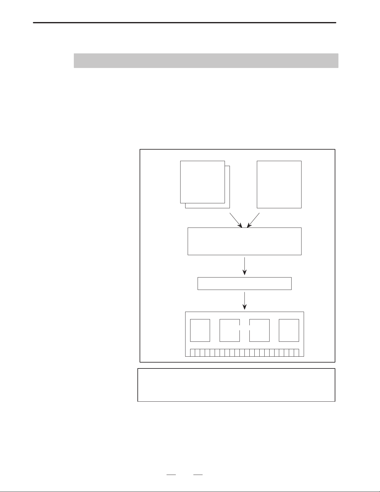
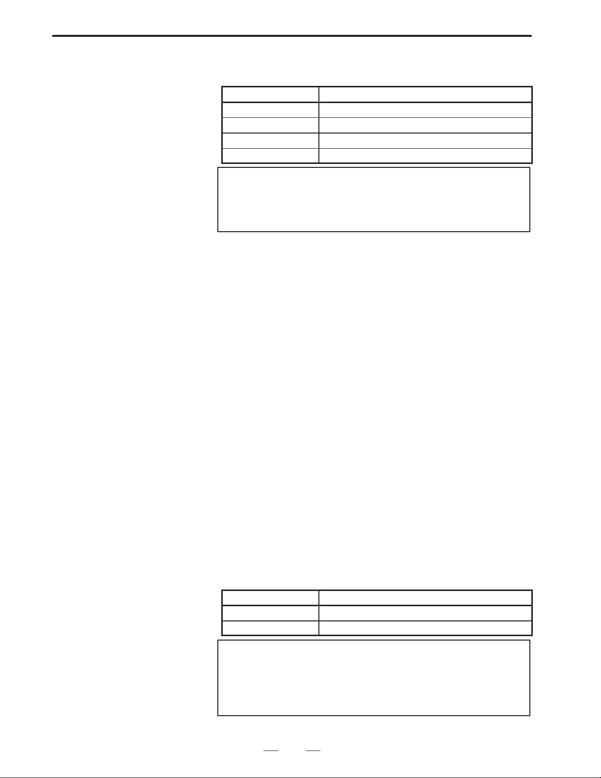
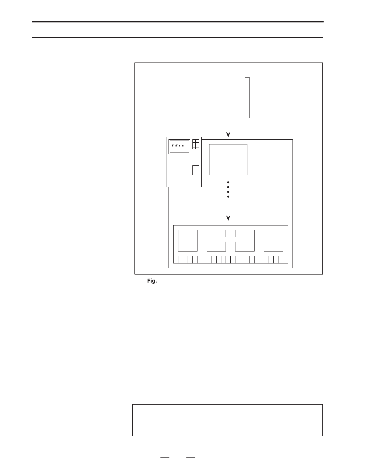
In Series 15–B, custom macro and P–CODE programs are created,
registered and saved as follows.
Series 15–B
F–ROM
P–CODE program
(2) (3)
D–RAM
P–CODE program
(1)
T ape
Custom macro
program
(4)
(5)
(6)
System P
Memory card
P–CODE file
ROM cassette
P–CODE
program
(7) or (8)
PMC–
writer
(7)
(9)
(8)
Personal
computer
(7)
Custom macro program
(8) or (9)
No. Process Performed by
(1) Compile Series 15–B macro compiler
(2) ROM write Series 15–B macro compiler
(3) Activate P–CODE program CNC
(4) Load Boot system
(5) Save Boot system
(6) Load Boot system
(7) Compile System P macro compiler
(8) Compile Personal computer macro compiler
(9) Compile Personal computer macro compiler
7
Page 11

2. MACRO COMPILER
B–62073E–2/03
2.3
USE OF MACRO
COMPILER
2.3.1
Registering a P–CODE
Program in F–ROM
Using a Memory Card
(When Compiled with a
Personal Computer)
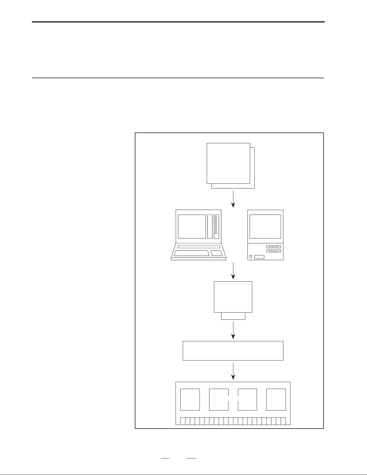
The P–CODE program created by compiling a custom macro program
can be registered in F–ROM in any one of the following ways:
(1) When the P–CODE program is compiled with a personal computer,
it can be registered in F–ROM using a memory card.
(2) When the P–CODE program is compiled with a personal computer
or System P, it can be registered in F–ROM using a ROM cassette.
(3) Series 15–B can compile the P–CODE program for registration in
F–ROM.
Note
The P–CODE program resident in F–ROM can be saved
onto a memory card via the boot system and copied to
another F–ROM unit.
This method uses a memory card to register a P–CODE program
compiled with a personal computer in the F–ROM unit of Series 15–B.
For how to compile a program, refer to the FAPT Macro Compiler (for
Personal Computer) Programming Manual (B–66102E).
Custom macro programs
Personal
computer
O9000 ;
#1=#2+#5 ;
:
:
M99 ;
Compile custom macro programs
into the P–CODE program.
Memory card
Boot system
Register
F–ROM
Save
Fig.2.3.1 (a) P–CODE Program Registration Using a Memory Card
8
Page 12
B–62073E–2/03
2.MACRO COMPILER
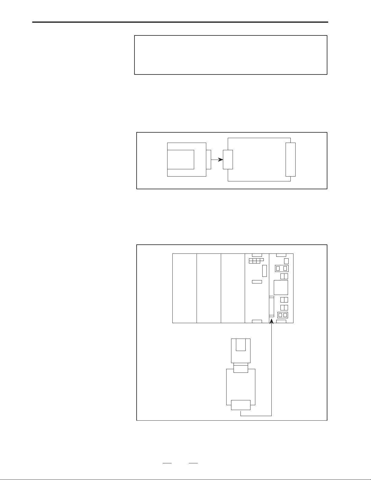
(1) Procedure for registering a P–CODE program in a memory card to
F–ROM
1) Insert the memory card in the memory card interface of the CNC
unit.
PMC PSU
Series 15–B
Memory card
Fig.2.3.1 (b) Mounting of a Memory Card
Note
The PMC slot is used as the memory card interface. The
memory card can be inserted or removed while the power
is turned on. When the boot system is active, make sure that
the main menu [see Fig. 2.3.1(c)] is displayed on the screen
before inserting or removing the memory card. Otherwise,
proper access is not made, and the contents of the memory
card files may be destroyed.
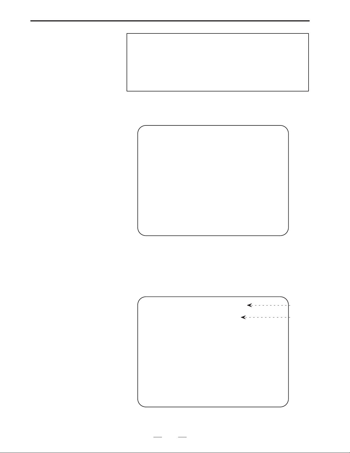
2) Turn on the power of the CNC unit while holding down the
page–up and page–down keys. The boot system is activated, and
the following screen appears.
SYSTEM MONITOR
1. SYSTEM DATA LOADING
2. SYSTEM DATA CHECK
3. SYSTEM DATA SAVE
4. FILE DATA BACKUP
5. END
*** MESSAGE ***
SELECT MODE AND HIT INPUT KEY
Fig.2.3.1 (c) Boot System Main Menu
9
Page 13

2. MACRO COMPILER
B–62073E–2/03
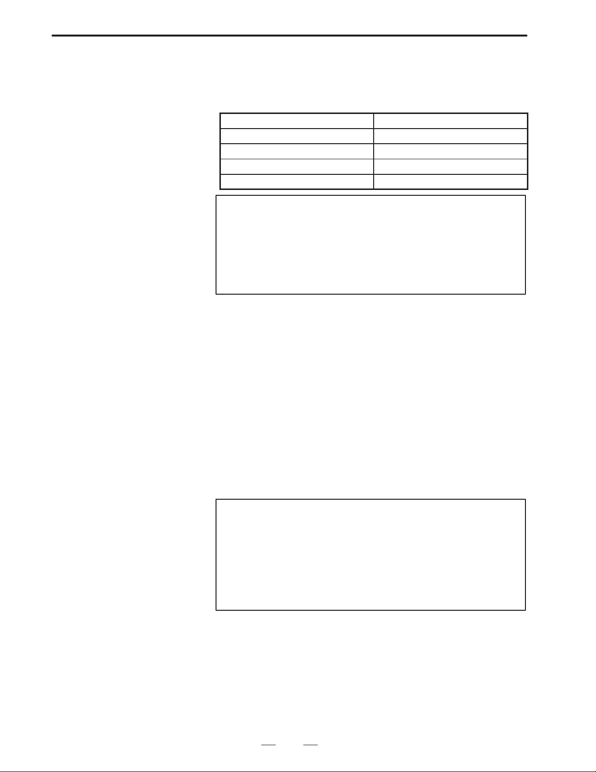
3) Select ”2. SYSTEM DATA CHECK” using the cursor keys and
press the input key. The contents of F–ROM are retrieved, and
the following information is displayed on the screen:
SYSTEM DATA CHECK
FILE DIRECTORY
1. OPTIONA3 ( 2)
2. HELP MSG ( 2)
3. DG SERVO ( 1)
4. NC BASIC (10)
5. PCD 256A ( 2)
6. PMC–NA0B ( 1)
7. MCR–CMPA ( 2)
END
*** MESSAGE ***
SELECT FILE AND HIT INPUT KEY
Fig.2.3.1 (d) DATA CHECK DIRECTORY Screen
Check this screen to see if any P–CODE programs are registered. If a
P–CODE program is already registered, its file name is displayed (see the
table below).
2.3.1 P–CODE File Names)
File name
PCD 256A For systems without a sub–CPU (256K bytes)
PCD 512A For systems without a sub–CPU (512K bytes)
PCD 256M For systems with a sub–CPU (256K bytes)
PCD 512M For systems with a sub–CPU (512K bytes)
Description
4) If a P–CODE file is already registered, delete it. To delete a
P–CODE file, select it with the cursor, then press the ”delete” key .
When no P–CODE file is registered, proceed to step 7.
5) The message “DELETE OK?” appears. Make sure that the selected
file is a P–CODE file, then press the input key. If the wrong file has
been selected, press the cancel key. The DATA CHECK
DIRECTORY screen [Fig. 2.3.1(d)] is then displayed again.
Note
When an attempt is made to delete a system file, such as
a CNC program or the macro compiler, the message
”PROTECT FILE” appears on the screen and the attempt is
rejected. However, the system deletes user files, such as
the PMC ladder, without asking for confirmation. Once
deletion has started, the process cannot be halted. If no
backup file exists on a memory card or another storage
medium, the contents of the file cannot be restored in any
way. To avoid such inadvertent deletion of files, make sure
that the correct file has been selected before deleting it.
Also, back up user files at appropriate intervals.
10
Page 14

B–62073E–2/03
2.MACRO COMPILER
6) When the file has been successfully deleted, the message “DELETE
COMPLETED” appears. Press the input key. The DA TA CHECK
DIRECTORY screen [Fig. 2.3.1(d)] 1 is then displayed again.
Confirm that the P–CODE file is no longer listed.
7) Select ”END” and press the input key. The main menu [Fig.
2.3.1(c)] is then displayed again.
8) Select “1. SYSTEM DATA LOADING” using the cursor keys,
then press the input key . The directories in the memory card are
listed on the screen.
SYSTEM DATA LOADING
FILE DIRECTORY
1. LADDER1. ROM
2. LADDER2. ROM
3. TEST. DAT
4. MACRO. ROM
END
*** MESSAGE ***
SELECT FILE AND HIT INPUT KEY
Fig.2.3.1 (e) DATA LOADING DIRECTORY SCREEN
Note
If a ROM cassette error occurs, check the title. When the
boot system has been activated by holding down the
page–up and page–down keys, the title should read:
SYSTEM DATA LOADING.
If this title is not displayed, turn off the system power once,
then turn it on again.
Title
For the functions of the boot system, see 2.3.5, (1) Methods of starting up
the boot system and the corresponding main menu functions.
9) Select the P–CODE file using the cursor keys, then press the
input key.
10)The message ”OK? INPUT/CANCEL” appears. To register the
selected program, press the input key . T o not register the selected
file cancel, press the ”cancel” key. The DATA LOADING
DIRECTOR Y screen [see Fig. 2.3.1 (e)] is then displayed again.
11
Page 15

2. MACRO COMPILER
B–62073E–2/03
Note
The boot system registers any file having the acceptable
format. Once registration has started, it cannot be halted.
If no backup file exists on a memory card or another storage
medium, the previously saved data of the file cannot be
restored in any way. To avoid such inadvertent registration
of files, make sure that the correct file has been selected
before registering it. Also, back up files at appropriate
intervals.
11)When the file has been successfully registered, the message
”PROGRAM COMPLETED” appears. Press the input key . The
DATA LOADING DIRECTORY screen [see Fig. 2.3.1 (e)] is
then displayed again.
12)Select “END” and press the input key. The main menu [Fig. 2.3.1
(c)] is then displayed again.
13)Select “2. SYSTEM DATA CHECK” to retrieve the contents of
F–ROM. After confirming that the P–CODE file has been
registered, press the input key to return the main menu [Fig. 2.3.1
(c)].
14)Select “END” on the main menu and press the input key. The
blinking message “LOADING CNC DAT A” appears. The CNC
starts up about ten seconds later.
15)Make sure that the registered P–CODE file operates normally.
16)Remove the memory card from the memory card interface. The
card can be removed even when the CNC power is on.
(2) Procedure for registering a P–CODE program in F–ROM to a
memory card
1) Insert the memory card in the memory card interface of the CNC
unit to activate the boot system. See steps 1 and 2 of 2.3.1 (1),
Procedure for registering a P–CODE program in a memory card
to F–ROM.
2) Select “3. SYSTEM DATA SAVE” using the cursor keys, then
press the input key. The contents of F–ROM are retrieved, and
the following information is displayed on the screen:
SYSTEM DATA SAVE
FILE DIRECTORY
1. OPTIONA1 ( 2)
2. HELP MSG ( 2)
3. DGTL SRV ( 1)
4. NC BASIC (10)
5. PCD 256A ( 2)
6. PMC–NA0B ( 1)
7. MCR–CMPA ( 2)
END
*** MESSAGE ***
SELECT FILE AND HIT INPUT KEY
Fig.2.3.1 (f) DATA SAVE DIRECTORY SCREEN
12
Page 16
B–62073E–2/03
2.MACRO COMPILER
3) Select one of the P–CODE files listed below using the cursor,
then press the input key.
File name Description
PCD 256A For systems without a sub–CPU (256K bytes)
PCD 512A For systems without a sub–CPU (512K bytes)
PCD 256M For systems with a sub–CPU (256K bytes)
PCD 512M For systems with a sub–CPU (512K bytes)
Note
System files, such as the CNC program or the micro
compiler, cannot be saved (if you attempt to save one of
these files, the message ”PROTECT FILE” is displayed).
4) The message “INPUT FILE NAME” appears. Input the file name
using the MDI key . A file must be named according to MS–DOS
file naming rules; that is, a file name consisting of up to eight
characters followed by a three–character or shorter extension.
During file name input:
The cursor can be moved using the cursor ( and ) keys.
The cancel key functions as the backspace key.
Pressing the reset key displays the DATA SAVE
DIRECTORY screen [Fig. 2.3.1 (f)] again.
Characters are input in the overwrite mode.
5) After inputting the file name, press the input key to save the file.
6) If the save operation terminates normally, the message “SAVE
COMPLETED” appears. Press the input key . The DATA SAVE
DIRECTORY screen [Fig. 2.3.1 (f)] is then displayed again.
7) Select “END” and press the input key . The main menu [Fig. 2.3.1
(c)] is then displayed again.
(3) Specifications and limitations of the memory card
(a) Specifications
The boot system of Series 15–B permits the use of commercially
available memory cards conforming to the following
specifications:
Standards : JEIDA Ver.4 or later
Capacity : 512K bytes or more
(b) P–CODE file size
When a P–CODE file is saved onto a memory card, its size is as
follows:
File capacity Size on memory card
256K#bytes 262272#bytes (256K#bytes + 128#bytes)
512K#bytes 524416#bytes (256K#bytes + 128#bytes)
Note
A P–CODE file cannot be divided and saved onto two or
more memory cards. Prepare a memory card having
enough capacity to save the whole file. Two or more
P–CODE files can be saved onto the same card.
13
Page 17
2. MACRO COMPILER
B–62073E–2/03
(c) Limitations
The boot system is capable of handling only root directory files.
Subdirectory files are not accessible. A void using a memory card
with a subdirectory for the boot system.
2.3.2
Registering the
P–CODE Program in
F–ROM Using a ROM
Cassette (When the
P–CODE Program has
been Compiled with
the System P or a
Personal Computer)
A P–CODE program compiled with the System P or a personal computer
can be registered in F–ROM of Series 15–B by using a ROM cassette.
For how to compile and write programs to ROM, refer to F ANUC System
P series FAPT Macro Compiler Operator’s Manual (B–66032E) and
FAPT Macro Compiler (for Personal Computer) Programming Manual
(B–66102E).
Custom macro programs
O9000 ;
#1=#2+#5 ;
:
:
M99 ;
System P
or
Personal
computer
Writing the P–CODE
program into ROM
ROM cassette
Boot system
Register
F–ROM
Fig.2.3.2 (a) Registering the P–CODE Program Using a ROM Cassette
14
Page 18
B–62073E–2/03
(1) Writing data into a ROM cassette
2.MACRO COMPILER
System P
ROM cassette
or
Printed circuit board for
the ROM cassette adapter
PMC writer
Personal
computer
RS–232–C
POM cassette adapter
Series 15–B
Fig.2.3.2 (b) Writing Data into a ROM Cassette
The following are required to write data into a ROM cassette:
1) System P or a personal computer
2) RS–232–C cable
3) PMC writer (A13B–0126–B002)
4) Printed circuit board for the ROM cassette adapter
(A16B–1212–0182)
5) ROM cassette: A02B–0094–C163 for 1M–bit ROM (256K
bytes)/A02B–0094–C164 for 2M–bit ROM (512K bytes)
6) Compiler for System P: COMPILER (A08B–0035–J720 for
P–G Mate/A08B–0036–J720 for P–G Mark II)/LIBRARY
(A08B–0036–J721 for both P–G Mate and P–G Mark II)
or F APT macro compiler for a personal computer (A08B – 9001 – J540
#EN03) /FAPT macro library (A08B–9001–J640#ZZ03)
7) ROM cassette adapter (A20B–2000–0760)
15
Page 19
2. MACRO COMPILER
B–62073E–2/03
Note
Items 1) to 5) were required when compiling programs for
Series 15–A using System P or a personal computer. Items
6) and 7) have been required for Series 15–B additionally.
(2) Procedure for registering a P–CODE program in a ROM cassette to
F–ROM
1) Connect the ROM cassette into which the program has been
written using System P or a personal computer to the ROM
cassette adapter (A20B–2000–0760).
ROM
cassette
Fig.2.3.2 (c) Connection of the ROM Cassette to
the ROM Cassette Adapter
ROM cassette adapter
(A20B–2000–0760)
2) T urn off the power of the CNC unit, then insert the ROM cassette
adapter into the mini slot of the CNC unit. The mini slot is on
the PSU and is protected with a cover when not in use.
PMC PSU
Series 15–B
ROM cassette
ROM cassette adapter
Fig.2.3.2 (d) Connection of the ROM Cassette Adapter to the CNC Unit
16
Page 20
B–62073E–2/03
2.MACRO COMPILER
Note
Be sure to turn off the power of the CNC unit before inserting
or removing the adapter. Inserting or removing the adapter
while the CNC power is on can not only damage the CNC
unit and the ROM cassette but can also destroy
battery–retained data, such as NC programs and
parameters.
3) T urn on the power of the CNC unit while holding down the cursor
( and ) keys. The boot system is activated, and the following
screen appears:
SYSTEM MONITOR
1. SYSTEM DATA LOADING
2. SYSTEM DATA CHECK
3. SYSTEM DATA SAVE
4. FILE DATA BACKUP
5. END
*** MESSAGE ***
SELECT MODE AND HIT INPUT KEY
4) Check the contents of F–ROM. If a P–CODE program is already
registered, delete it. For the deletion procedure, see 2.3.1 (1)
Procedure for registering a P–CODE program in a memory card
to F–ROM, steps 3 to 7.
5) Select ”SYSTEM DATA LOADING” using the cursor keys, then
press the input key. The following contents of the ROM cassette
are read and displayed on the screen:
SYSTEM DATA LOADING (CASSETTE)
P–CODE 256K (WITHOUT SUB–CPU)
Title
ROM
type
*** MESSAGE ***
SELECT FILE AND HIT INPUT KEY
Fig.2.3.2 (e) DATA LOADING DIRECTORY SCREEN (for ROM Cassette)
17
Page 21
2. MACRO COMPILER
B–62073E–2/03
The type of mounted ROM cassette (P–CODE file) is displayed
(see the table below). If the displayed ROM cassette type does not
agree with that of the connected ROM cassette, check the ROM
cassette.
ROM cassette/P–CODE file Display
1M–bit ROM without a sub–CPU P–CODE 256K (without sub–CPU)
2M–bit ROM without a sub–CPU P–CODE 512K (without sub–CPU)
1M–bit ROM with a sub–CPU P–CODE 256K (with sub–CPU)
2M–bit ROM with a sub–CPU P–CODE 512K (with sub–CPU)
Note
If an alarm related to the memory card occurs or when
displaying memory card directories, confirm the title. When
the CNC unit has been activated with the cursor ( and )
keys pressed down, the title should read:
SYSTEM DATA LOADING (CASSETTE)
If this title is not displayed, activate the CNC unit again.
6) The message “OK? INPUT/CANCEL” appears. To register the
P–CODE file, press the input key. To not resister the P–CODE
file, press the “cancel” key. Then the main menu [Fig. 2.3.1 (c)]
is then displayed again.
7) When the file has been successfully registered, the message
“PROGRAM COMPLETED” appears. Press the input key . The
main menu [Fig. 2.3.1 (c)] is then displayed again.
8) Select “2. SYSTEM DATA CHECK” to retrieve the contents of
F–ROM. After confirming that the P–CODE file has been
registered in F–ROM. Press the input key to return the main
menu [Fig. 2.3.1 (c)].
9) Turn off the power of the CNC unit, and remove the ROM
cassette adapter from the mini slot. After removing the adapter,
place the cover over the slot to protect it.
Note
Avoid using the CNC unit while the ROM cassette remains
in its mini slot. If the CNC unit is used without removing the
ROM cassette, the data stored in the ROM cassette takes
precedence, disabling the use of the micro compiler and
P–CODE program resident in F–ROM.
For more information, see 2.3.4 (3), Priority of the micro
compiler and P–CODE program.
10)Make sure that the registered P–CODE program operates
normally.
18
Page 22
B–62073E–2/03
2.MACRO COMPILER
2.3.3
Compiling and
Registering Custom
Macro Programs in
F–ROM Using the
Series 15–B
Custom macro programs resident in the part–program edit memory can
be compiled and registered in F–ROM using the Series 15–B.
Custom macro programs
O9000 ;
#1=#2+#5 ;
:
:
M99 ;
Part–program
edit memory
Series 15–B
Compile
Register
F–ROM
Fig.2.3.3 (a) Compilation and Registration Using the Series 15–B
(1) Procedure for operating the micro compiler
1) In part–program edit memory register all the custom macro
programs to be compiled into the P–CODE program.
Be sure to compile a program into one P–CODE file at a time.
Compiling a custom macro program into several P–CODE files
and then combining them into one file is not allowed.
The compiler only checks programs for basic syntax error.
2) Set the compile parameters.
Specify parameters necessary for program compilation, including
those related to the conditions for P–CODE program generation and
the correspondence between call codes and program numbers. The
alarm message “POWER MUST BE OFF” may be displayed on the
screen while changing the compile parameters; ignore the message
and proceed with the parameter setting.
Note
For details about the compile parameters, see 2.4, Compile
Parameters.
19
Page 23

2. MACRO COMPILER
B–62073E–2/03
3) When all the parameters have been set, turn off the power of the
CNC.
4) T urn on the power of the CNC unit while holding down MDI keys
4 and 6. The utility is activated, and the following screen appears:
FANUC SERIES 15
1. MACRO COMPILER
2. TROUBLE GUIDANCE
3. END
?
Fig.2.3.3 (b) Utility Screen
5) Select “1. MACRO COMPILER” from the menu by typing ”1”,
then press the input key . The macro compiler is activated, and the
menu screen appears.
FANUC SERIES 15 NC PROGRAM COMPILER
1. COMPILE
2. COMPILE AND ROM WRITE
3. COMPILE AND VERIFY ROM
4. END
?
Fig.2.3.3 (c) Menu Screen
6) Select the desired operation from the menu.
1 COMPILE: Compile custom macro programs. The
P–CODE file is not registered in F–ROM.
2 COMPILE AND ROM WRITE: Compile custom macro
programs and register the P–CODE file in F–ROM.
3 COMPILE AND VERIFY ROM: Compile custom macro
programs and verify the compiled file with the P–CODE file
in F–ROM.
4 END: T erminate the compiler and return to the utility screen
[Fig. 2.3.3 (b)].
20
Page 24

B–62073E–2/03
2.MACRO COMPILER
Note
Since the compiled P–CODE file is also written on RAM of
the CNC unit, the P–CODE program can be executed after
the complier is terminated, irrespective of whether it is
registered in F–ROM. While the selected operation is being
performed, its number is displayed next to the question
mark (?). The question mark disappears when the
operation is completed.
7) The status of the operation being performed is displayed in the
status indication area on the screen.
FANUC SERIES 15 NC PROGRAM COMPILER
1. COMPILE
2. COMPILE AND ROM WRITE
3. COMPILE AND VERIFY ROM
4. END
The following data items are displayed here depending on the selected
operation, one of COMPILE, F–ROM
ERASE & BLANK CHECK, F–ROM WRITE, and
F–ROM VERIFY.
Status indication area
Fig.2.3.3 (d) Status Indication Area
(1) COMPILE
Compilation can be suspended while it is in progress by pressing the
reset key.
COMPILE
PROGRAM NO. 9010 (Note 1)
BLOCK NO. 120 (Note 2)
P–CODE SIZE 00012EF0 (Note 3)
ALARM NO. 0000 (Note 4)
DIAGNOSIS 110 (Note 5)
Fig.2.3.3 (e) Status Indication (COMPILE)
(2) F–ROM ERASE & BLANK CHECK
The displayed indication remains unchanged while this operation is
being performed. This operation cannot be suspended while it is in
progress.
21
Page 25

2. MACRO COMPILER
F–ROM ERASE & BLANK CHECK
ADDRESS 00000000 (Note 6)
ALARM NO. 0000 (Note 4)
DIAGNOSIS 140 (Note 5)
Fig.2.3.3 (f) Status Indication (ERASE)
B–62073E–2/03
(3) F–ROM WRITE
Writing of F–ROM can be suspended while it is in progress by
pressing the reset key. However, avoid suspending this operation
while it is in progress since doing so will shorten the life of the
F–ROM unit.
F–ROM WRITE
ADDRESS 00027A00 (Note 6)
ALARM NO. 0000 (Note 4)
DIAGNOSIS 150 (Note 5)
Fig.2.3.3 (g) Status Indication (WRITE)
(4) F–ROM VERIFY
Verification of F–ROM can be suspended while it is in progress by
pressing the reset key suspending this processing does not affect the
life of the F–ROM unit.
F–ROM VERIFY
ADDRESS 00027A00 (Note 6)
ALARM NO. 0000 (Note 4)
DIAGNOSIS 160 (Note 5)
Fig.2.3.3 (h) Status Indication (VERIFY)
22
Page 26
B–62073E–2/03
O tion
256K#bytes
2.3.4
P–CODE Program
2.MACRO COMPILER
Notes
1 Number of the custom macro program being compiled
(number preceded by an O)
2 Block number assigned by the macro compiler
3 Total size of the compiled P–CODE file
4 Alarm number of the error. If an error occurs, the micro
compiler suspends its operation. For details, see 2.5,
ERROR CODE LIST.
5 This information is displayed for maintenance purposes
only. No special attention is required.
6 Address in F–ROM to which data is being written or for
which verification is being performed
(1) P–CODE file size
The size of a P–CODE file can be either 256K bytes or 512K bytes.
Whether the size is 256K bytes on 512K bytes depends on the setting
of parameter No.8500 (P512) and whether the option (macro executor
user program memory) is used.
#7 #6 #5 #4 #3 #2 #1 #0Address
8500 P512
Bit No.
Option : Macro executer user program memory with a
capacity of 512K bytes (A02B–0162–J607)
P512 0 1
p
Used
Not used
512K#bytes
Error
Error : If 1 is specified for P512 when the option is not used,
the P–CODE file size selection error (error number
4109) occurs. For details, see 2.3.5 (3), F–ROM
errors and corrective action.
(2) P–CODE program size
The maximum size of a P–CODE program to be created depends on
the selected P–CODE file size as shown in the table below.
File size
256K#bytes 192K#bytes 128K#bytes
512K#bytes 416K#bytes 384K#bytes (Note)
System without
sub–CPU
System with sub–CPU
Note
When a file size of 512K bytes is selected for a system with
a sub–CPU, a total of 384K bytes is allocated as the
P–CODE program area. Of these 384K bytes, 128K bytes
are used for the execution macro.
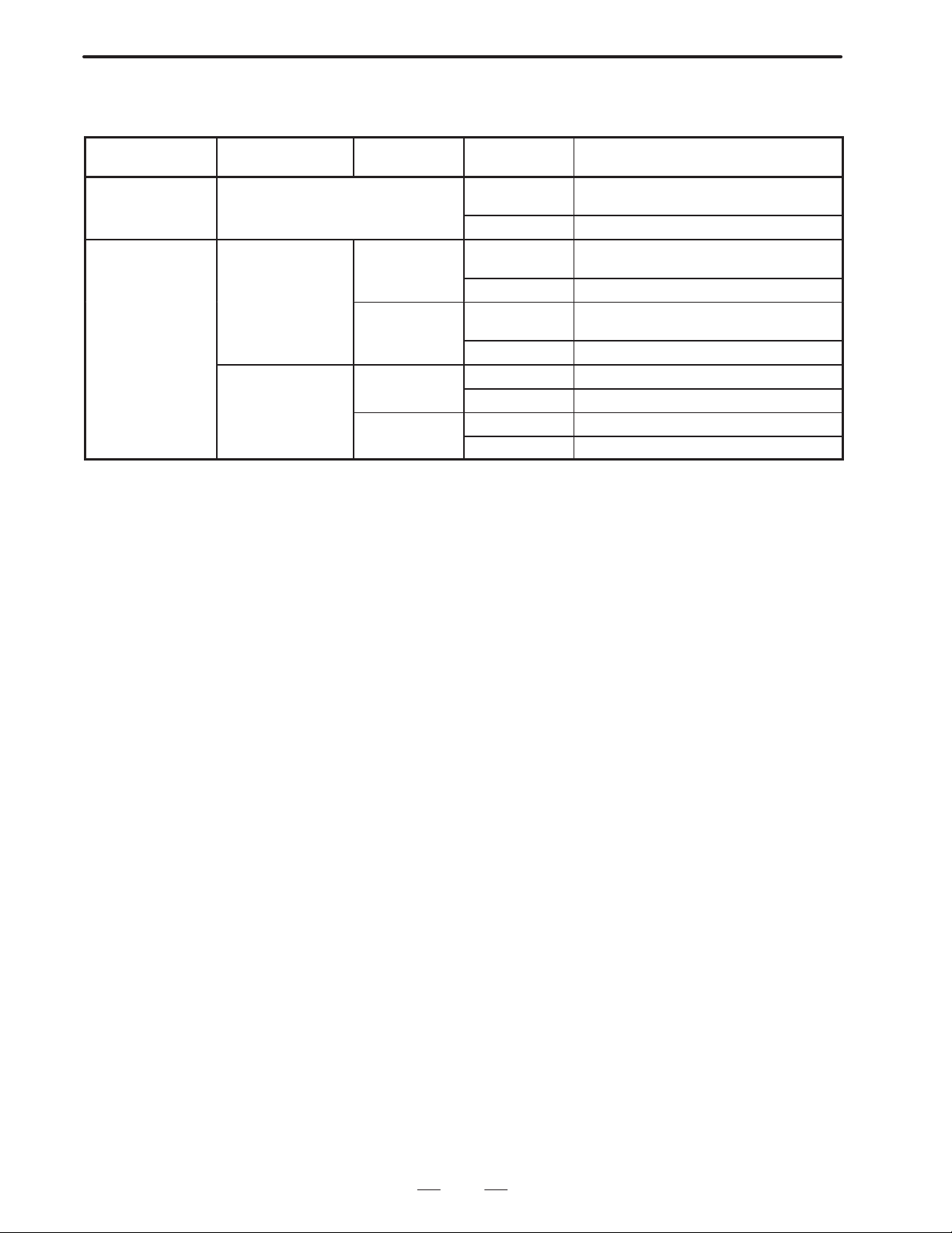
(3) Priority of the macro compiler and P–CODE program
The priority of the macro compiler and P–CODE program is as
follows.
23
Page 27
2. MACRO COMPILER
1. P–CODE program in resident ROM cassette
2. P–CODE program in resident F–ROM
3. Macro compiler
}
Priority changes depending on how the CNC unit is activated.
B–62073E–2/03
P–CODE program
in ROM cassette
Resident No effect on priority no ope The P–CODE program in the ROM cas-
Not resident Resident Resident no ope The P–CODE program in F–ROM is acti-
no ope : Turn on the power of the CNC unit.
“4”, “6” : Hold down MDI keys 4 and 6 while turning on the power of the CNC unit.)
P–CODE program
in F–ROM
Not resident Resident no ope The P–CODE program in not activated.
Macro
compile
Not resident no ope The P–CODE program in F–ROM is acti-
Not resident no ope The P–CODE program in not activated.
How to
activate CNC
sette is activated.
“4”, “6” The compiler is not activated.
vated.
“4”, “6” The compiler is activated.
vated.
“4”, “6” The compiler is not activated.
“4”, “6” The compiler is activated.
“4”, “6” The compiler is not activated.
Result
24
Page 28
B–62073E–2/03
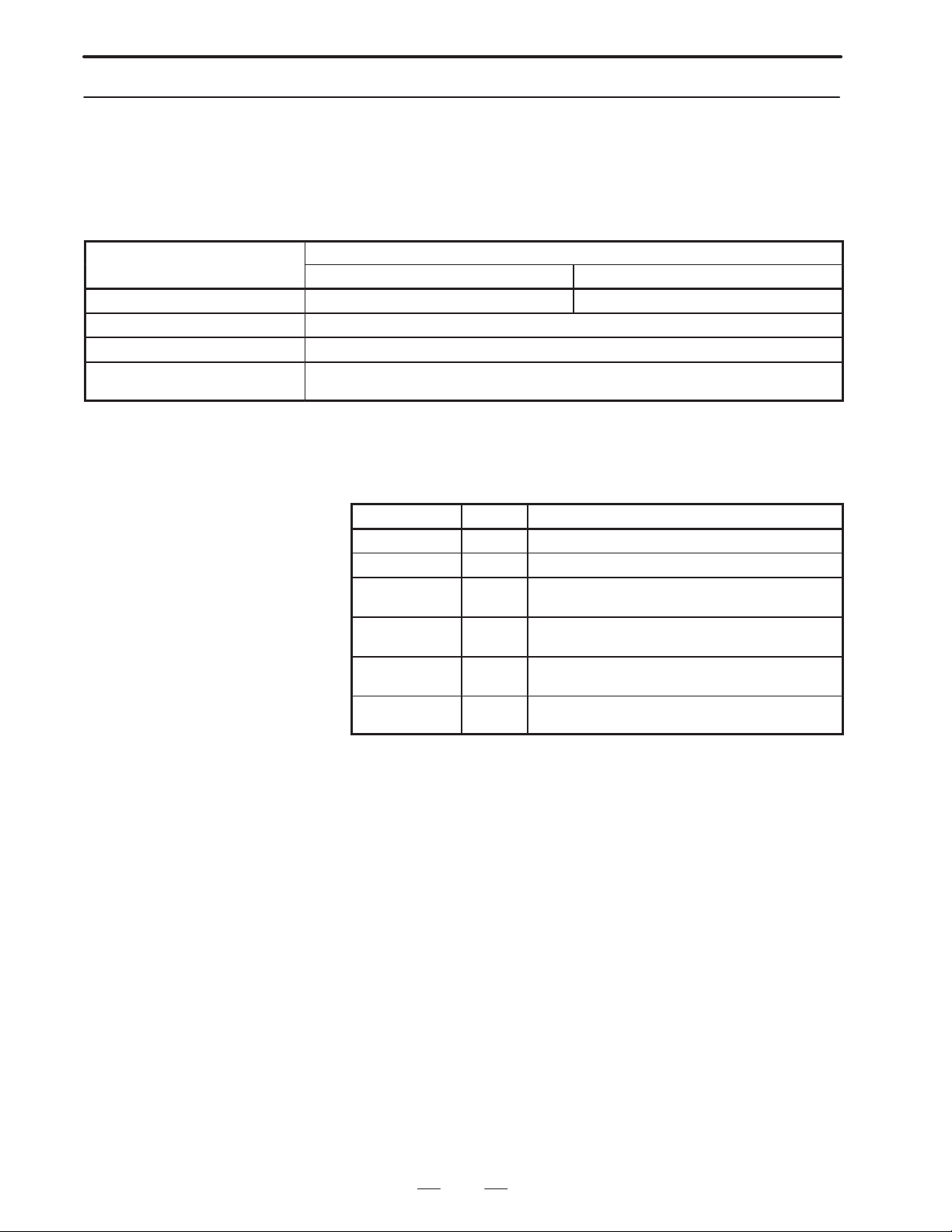
Main menu item
2.MACRO COMPILER
2.3.5
F–ROM
SYSTEM DATA LOADING Load files from memory card to F–ROM. Load files from ROM cassette to F–ROM.
SYSTEM DATA CHECK List files registered in F–ROM and check ROM data.
SYSTEM DATA SAVE Save files registered in F–ROM to memory card.
FILE DATA BACKUP Save battery–retained data (NC programs, parameters, etc.) to memory card and
(1) Methods of starting up the boot system and the corresponding main
menu functions
The following table lists the main menu items and their functions.
(The function of SYSTEM DA TA LOADING changes depending on
how the boot system is started up.)
How to start up the boot system
“page up key”. “page down key” “”, “”
restore these data.
(2) Files in F–ROM
The following table lists the files shown on the SYSTEM DATA
CHECK DIRECTORY screen that are related to the micro compiler
executer.
File name Type Description
MCR–CMPA S Micro compiler for systems without a sub–CPU
MCR–CMPM S Micro compiler for systems with a sub–CPU
PCD 256A U P–CODE file for systems without a sub–CPU
PCD 512A U P–CODE file for systems without a sub–CPU
PCD 256M U P–CODE file for systems with a sub–CPU
PCD 512M U P–CODE file for systems with a sub–CPU
(256K bytes)
(512K bytes)
(256K bytes)
(512K bytes)
File type
S : System files provided by FANUC.
Note) These files are used to compile custom macro programs with
the Series 15–B.
The following operations cannot be performed for these files:
Saving files to memory card
Deleting files from F–ROM
U : User–defined data files. These files are accessible in every
operation.
25
Page 29
2. MACRO COMPILER
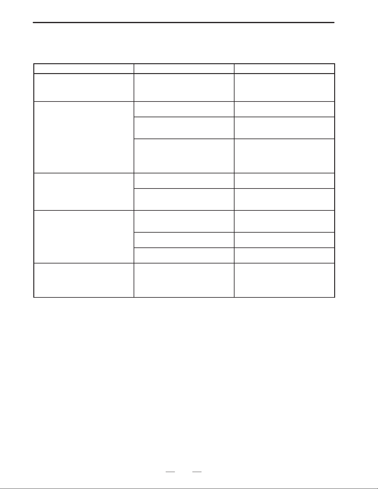
(3) F–ROM errors and corrective action
The following table lists F–ROM errors caused by erroneous
operations and the corrective actions to be taken for then.
Error Cause Corrective action
Error code 4109 is output. Parameter No.8500 is set to 512K
The compiler is not activated when the
CNC is powered up with MDI keys 4
and 6 pressed down.
The newly registered P–CODE program is not activated. The old one is
activated instead.
The P–CODE program does not operate at all.
The meassage ”USER FILE
(P–CODE): ILLEGAL KIND FILE” is
displayed when the CNC power is
turned on.
bytes when the option (user program
memory with a capacity of 512K bytes)
is not used.
The ROM cassette is still in the slot. Turn off the CNC power and remove
The compiler is not registered in
F–ROM.
The wrong compiler is registered. The
compiler for systems without a sub–
CPU is inadvertently registered for
systems with a sub–CPU, or vice
versa.
The ROM cassette is still in the slot. Turn off the CNC power and remove
”COMPILE AND VERIFY ROM” was
selected instead of ”COMPILE AND
ROM WRITE” when compiling files
The P–CODE program is not registered in F–ROM.
The compiler was terminated before
compilation was completed.
Parameters are not set. Set the parameters correctly , then re–
The P–CODE program for the wrong
system is registered. The program for
systems without a sub–CPU is inadvertently registered for systems with a
sub–CPU, or vice versa.
B–62073E–2/03
Check and correct the parameter.
the cassette.
Check the SYSTEM DATA CHECK
DIRECTORY screen. If the compiler is
not listed there, register it.
Check the SYSTEM DATA CHECK
DIRECTORY screen. If the wrong
compiler is listed there, register the
correct one.
the cassette.
Select ”COMPILE AND ROM WRITE”
and execute it.
Check the SYSTEM DATA CHECK
DIRECTORY screen. If the P–CODE
program is not listed there, register it.
Re–execute compilation.
execute compilation.
Check the SYSTEM DATA CHECK
DIRECTORY screen. Delete the registered P–CODE program, then register
the correct one or compile the programs.
26
Page 30

B–62073E–2/03
2.MACRO COMPILER
2.4
COMPILE PARAMETER
#7 #6 #5 #4 #3 #2 #1 #0Address
Bit No.
8500 0 P512 VERY
Parameter input
Data format : bit type
VERY When “COMPILE AND ROM WRITE” is executed, F–ROM is
0 : not verified
1 : verified
P512 The size of the P–CODE program to be output to F–ROM is
0 : 256K bytes (the same size as that used in the 1M bit ROM
cassette)
1 : 512K bytes (the same size as that used in the 2M bit ROM
cassette)
#4 Always specify a “0.”
#7 Always specify a “1.”
#7 #6 #5 #4 #3 #2 #1 #0Address
8501 SEQN
Parameter input
Data format : bit type
SEQN Outputs sequence number to P–CODE program
0 : does not
1 : does
#7 #6 #5 #4 #3 #2 #1 #0Address
8502 NPEF TMCC EUI0 DMV2 DBG SBK VAR DIR
Parameter input
Data format : bit type
DIR Displays directory of P–CODE program.
0 : does not
1 : does
VAR In case of debug mode, displays macro variable for macro
compiler
0 : does not
1 : does
SBK Single block stop when conversational macro is started up in
debugging function of conversational macro
0 : does not
1 : does
DBG Execution of macro compiler in debug mode
0 : does not perform
1 : performs
Note) DIR, VAR, SBK are enabled only when debugging mode (DBG
= 1).
Auxiliary macro cannot be executed during debugging mode
DMV2 When not in the debug mode, micro compiler variables are
0 : not displayed
27
Page 31

2. MACRO COMPILER
B–62073E–2/03
1 : displayed
EUI0 For the P–CODE program (execution, conversational, and
auxiliary macros), the UI and UO signals range from
0 : UI00/UO00 to UI15/UO15
1 : EUI00/EUO00 to EUI15/EUO15
TMCC Macro calls by T codes are
0 : invalid
1 : valid
NPEF In RS–232–C control by conversational macros, the end of file
(EOF) mark (%) is
0 : output
1 : not output
#7 #6 #5 #4 #3 #2 #1 #0Address
8503 VR7 VR6 VR5 VR4 VR3 VR2 VR1 VR0
Parameter input
Data format: bit type
VR0 Macro variable for macro compiler (#100–149)
0 : uses the same as normal custom macro
1 : uses one for macro compiler
VR1 Macro variable for macro compiler (#150–199)
0 : uses the same as normal custom macro
1 : uses one for macro compiler
VR2 Macro variable for macro compiler (#500–549)
0 : uses the same as normal custom macro
1 : uses one for macro compiler
VR3 Macro variable for macro compiler (#550–599)
0 : uses the same as normal custom macro
1: uses one for macro compiler
VR4 Macro variable for macro compiler (#600–699)
0 : uses the same as normal custom macro
1 : uses one for macro compiler
VR5 Macro variable for macro compiler (#700–799)
0 : uses the same as normal custom macro
1 : uses one for macro compiler
VR6 Macro variable for macro compiler (#800–899)
0 : uses the same as normal custom macro
1 : uses one for macro compiler
VR7 Macro variable for macro compiler (#900–999)
0 : uses the same as normal custom macro
1 : uses one for macro compiler
#7 #6 #5 #4 #3 #2 #1 #0Address
8507 PMC–NB STDM ECAN
Parameter input
Data type: Bit type
ECAN While data receiving (G335) or data sending (G336) is in the
wait state under conversational macro RS–232–C control,
pressing the CANCEL key on the MDI/CRT panel:
28
Page 32

B–62073E–2/03
2.MACRO COMPILER
0 : Does not suspend data sending or receiving.
1 : Cancels the wait state for data sending or receiving.
STDM On the conversational macro screen, status display (mode and
status display) is:
0 : Not masked.
1 : Masked.
PMC-NB If the system features PMC–NB, writing or reading of
two–byte or four–byte data by G310 is done in the:
0 : PMC–NA format.
Two–byte data :
The high–order byte is assigned A. The low–order byte is
assigned A + 1.
Four–byte data :
The bytes are read or written in a sequence such that the
high–order byte is assigned the lowest address A, while the
low–order byte is assigned the highest address A + 3.
1 : PMC–NB format.
Two–byte data :
The low–order byte is assigned A. The high–order byte is
assigned A + 1.
Four–byte data :
The bytes are read or written in a sequence such that the
low–order byte is assigned the lowest address A, while the
high–order address is assigned the highest address A + 3.
2 bytes 4 bytes
A
A+1
#7 #6 #5 #4 #3 #2 #1 #0Address
8508 EXT1 CUTL BCAL ONMK SCAL TCAL ACL2 ACL1
A
A+1
A+2
A+3
Parameter input
Data format: bit type
ACL1 Sub program call by designated code (O9004/#146)
0 : disabled
1 : enabled
ACL2 Sub program call by designated code (O9005/#147)
0 : disabled
1 : enabled
TCAL Sub program call by T code (O9000/#149)
0 : disabled
1 : enabled
SCAL Sub program call by S code (O9029/#147)
0 : disabled
1 : enabled
ONMK O,N number display in conversational macro screen
29
Page 33

2. MACRO COMPILER
B–62073E–2/03
0 : performs
1 : does not perform
BCAL Sub program call by B code (O9028/#146)
0 : disabled
1 : enabled
CUTL Cutting distance
0 : does not integrate
1 : integrates
EXT1 Reference/writing of CNC program, reading/ preset of cutting
distance function, and circuit control function
0 : does not perform
1 : performs
#7 #6 #5 #4 #3 #2 #1 #0Address
8509 PGMP PTCR MODC EVF2 EVF1
Parameter input
Data format: bit type
EVF Expanded conversational macro exclusive variable (#40000–) is
0: floating decimal point format
1: fixed decimal point format
EVF2 Format of conversational macro special variables (#30000 to
#39999)
0: Floating–point
1: Fixed–point
MODC Macro modal call
0: Call after move (corresponding to G66)
1: Block–by–block call (corresponding to G66.1)
PTCR CR code output after LF at the time of macro variable data
output
0: Outputs no CR code.
1: Outputs a CR code twice.
PGMP
Calling a P–CODE by using an M code, S code, T code, B code, M
codes specifying a range, or a specific code during a P–CODE call by
a G code, and calling a G code during a P–CODE call by using an M
code, S code, T code, B code, M codes specifying a range, or a
specific code are:
0 : permitted
1 : not permitted (codes are executed in the normal way)
Address
8510 Sub program M–CODE for calling 09001
8511 Sub program M–CODE for calling 09002
8512 Sub program M–CODE for calling 09003
Parameter input
Data format : word type
Data range : 0 to 9999
Specifies M–CODE to perform sub program call by M–CODE.
30
Page 34

B–62073E–2/03
Address
8513 Custom macro G–CODE for calling O9010
8514 Custom macro G–CODE for calling O9011
8522 Custom macro G–CODE for calling O9019
2.MACRO COMPILER
Parameter input
Data format : word type
Data range : 1 to 255 (except for 65 to 67)
Specifies G–CODE to perform macro call by G–CODE.
Address
8523 Custom macro M code to call O9020
8524 Custom macro M code to call O9021
8532 Custom macro M code to call O9029
Parameter input
Data format : word type
Data range : 0 to 9999
Specifies M–CODE to perform macro call by M code.
Address
8533 M code for calling a user program
Parameter input
Data type : Word
Valid data range : 0 to 99
Note) M00, M01, M02, M30, M98, and M99 cannot be used to call a user
program.
A P–CODE program (execution macro program) called by a user program
can call another user program as a subprogram, according to the specified
M code.
Address
8536
Value of conversational macro execution control variable 1 when turning on power
Parameter input
Data format : word type
Data range : 0 to 9999
Sets the program number of the first conversational macro to be executed
after power–on. This value is set in conversational macro execution
control variable 1 (#8500).
Address
8537
Value of conversational macro execution control variable 2 when turning on power
Parameter input
Data format : word type
Data range : 0 to 9999
31
Page 35

2. MACRO COMPILER
B–62073E–2/03
Sets the program number of the auxiliary macro to be executed at
power–on. This value is set in conversational macro execution control
variable 2 (#8600).
Address
8538 Calls by range specified M–CODE, lower limit M–CODE
8539 Calls by range specified M–CODE, upper limit M–CODE
Parameter input
Data format : word type
Data range : 0 to 9999
Specifies the upper limit/lower limit value of the M–CODE for sub
program call by range specified M–CODE.
Note) The special M–CODES M00, M01, M02, M30, M99 cannot be
used even when inside the range.
Address
8540 Timeout period (seconds) for data receiving (G335) or data sending (G336)
under conversational macro RS–232C control
Parameter input
Data type : Word
Units of data : Seconds
Valid data range : 0 to 180
Note) If zero is set, no timeout occurs in either data sending or receiving.
Address
8541 Conversational macro debug start key
Parameter input
Data format : byte type
Data range : 1 to 21
After the single block stop of the conversational body macro, when in
conversational macro debug mode, set the key code for restarting. Refer
to (Note) for the correspondence between the key code to be set and the
key.
Address
8542 Conversational macro debug single block switching key
Parameter input
Data format : byte type
Data range : 1 to 21
Set the key code for switching ON/OFF the single block of the
conversational body macro when in conversational macro debug mode.
Refer to (Note) for the correspondence between the key code to be set and
the key.
Address
8543 Conversational macro debug trigger point setting key
Parameter input
Data format : byte type
Data range : 1 to 21
32
Page 36

B–62073E–2/03
2.MACRO COMPILER
Set the key code for executing the conversational body macro up to trigger
point when in conversational macro debug mode. Refer to (Note) for the
correspondence between the key note to be set and the key.
Note) Setting the MDI/CRT key for the conversational macro debug
function is as follows.
PAGE ± : 1 SOFT FUNCTION KEY 3:14
PAGE ° : 2 SOFT FUNCTION KEY 4:15
CURSOR LEFT : 5 SOFT FUNCTION KEY 5:16
CURSOR RIGHT : 6 SOFT FUNCTION KEY 6:17
INPUT : 8 SOFT FUNCTION KEY 7:18
SOFT FUNCTION KEY RIGHT : 11 SOFT FUNCTION KEY 8:19
SOFT FUNCTION KEY 1 : 12 SOFT FUNCTION KEY 9:20
SOFT FUNCTION KEY 2 : 13 SOFT FUNCTION KEY 10:21
SOFT FUNCTION KEY LEFT, POS, OFSET, and other keys used to
directly select a screen have specific functions. The functions of these
keys cannot be changed.
POS, OFSET, etc: Clears the current screen and displays the
corresponding NC screen.
SFT KEY LEFT: Terminates the conversational macro.
The 14” CRT can be set as SOFT FUNCTION KEY 1–SOFT
FUNCTION KEY 10,
and the 9” CRT can be set as SOFT FUNCTION KEY 1–SOFT
FUNCTION KEY 5. Further, set without giving importance to the key
setting.
Address
8544 Address to call O9004 (argument #146)
Parameter input
Data format : byte type
Data range : “A” to “Z” (character code)
Calls O9004 by the set address when parameter No. 8508 ALC1 is 1. The
command value of that address is stored as an argument in #146.
Address
8545 Address to call O9005 (argument #147)
Parameter input
Data format : byte type
Data range : “A” to “Z” (character code)
Calls O9005 by the set address when parameter No. 8508 ALC2 is 1. The
command value of that address is stored as an argument in #147.
Address
8546 Quantity
Parameter input
Data type : Byte
Valid data range : 0 to 40
Sets the number of G codes to be added for calling P–CODE macros.
33
Page 37

2. MACRO COMPILER
Address
8547 Conversational macro Trigger program number
B–62073E–2/03
Parameter input
Data format : long type
Data range : 0 to 9999
Set the trigger program number of the conversational macro when in
conversational macro debugging mode.
Address
8548 Conversational macro Trigger sequence number
Parameter input
Data format : long type
Data range : 0 to 99999
Set the trigger sequence number of the conversational macro when in
conversational macro debugging mode.
Address
8549 A number of conversational macro exclusive variables (#30000–)
Parameter input
Data format : word type
Data range : 0 to
The upper limit of the conversational macro exclusive variables is
0 : 30000+ (value of parameter No. 8549) 40–1
1 : 30000+ (value of parameter No. 8549) 100–1
Address
8550 A number of conversational macro exclusive variables (#40000–)
Parameter input
Data format : word type
Data range : 0 to
The upper limit of the conversational macro exclusive variables is
40000+ (value of parameter No. 8550)10–1
when parameter No. 8509 EVF is 0, and
40000+ (value of parameter No. 8550)30–1
when parameter No. 8509 EVF is 1.
Address
8551 First G–code number among the G codes to be called
Parameter input
Data type : Word
Valid data range : 0 to 9999
Sets the first G–code number among the G codes to be used to add G codes
for calling P–CODE macros.
34
Page 38

B–62073E–2/03
Address
8552 First program number among the programs to be called
2.MACRO COMPILER
Parameter input
Data range : Word
Valid data range : 0 and 9000 to 9999
Sets the first program number among the programs to be called by the G
codes added for calling P–CODE macros.
35
Page 39
2. MACRO COMPILER
Ô
B–62073E–2/03
2.5
ERROR CODE LIST
ФФФФФФФФФФФФФФФФФФФФФФФФФФФФФФФ
Error
code
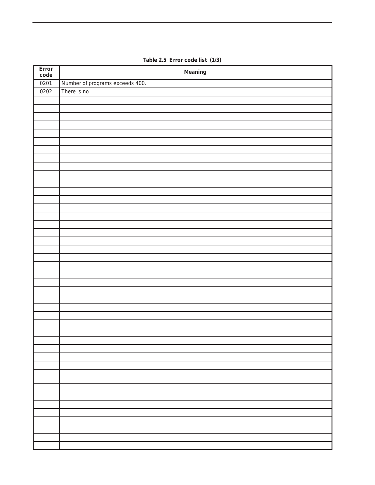
The meanings of error codes which should occur in compilation are given
below.
T able 2.5 Error code list (1/3)
Meaning
0201 Number of programs exceeds 400.
0202 There is not program.
1001 Block delete No. is provided with decimal point.
1002 Block delete No. is other than 1–9.
1003 The program No. is placed but not at the program head.
1004 The sequence No. is placed but not at the block head.
1005 There is an error in the NC statement format.
1006 Code other than EOB is placed at the end of the macro statement.
1007 The equal sign of macro statement is missing.
1008 The multiplexity of DO exceeds 3.
1009 The relational operator in the conditional expression is missing.
100A GOTO is missing after IF.
100B ’]’ of IF [<conditional expression>] is missing.
100A GOTO is missing after IF.
100B ’]’ of IF [<conditional expression>] is missing.
100C There is code other than EOB after GOTO n.
100D There is code other than EOB after DO m.
100E There is code other than EOB after END m.
100F The identification No. of END does not correspond to DO.
1010 There is no END corresponding to DO.
1011 DO after WHILE is missing.
1012 ’]’ of WHILE [<Conditional expression>] is missing.
1013 There is a block which is judged neither as an NC statement nor as a macro sentence.
1014 There is no DO corresponding to END.
1015 The directory program No. does not correspond to the program No. in the program.
1016 Program No. is missing at the head of program.
1201 The multiplexity of parentheses exceeds 5.
1202 ’]’ of #[expression>] is missing
1203 ’]’ of [<expression>] is missing.
1204 The second ’[’ of ATAN [<Expression>]/[<Expression>] is missing.
1205 ’/’ of ATAN [<Expression>]/[<Expression>] is missing.
1206 The first ’]’ of ATAN [<Expression>] is missing.
1207 ’]’ of the function [<Expression>] is missing.
1208 There is an error in the format of <Expression>.
1209 There is an error in the format of the <Expression> to the left of the substitution statement.
120A There is an error in the format of the <Expression> in <Address> [<Expression>], or <Address>–[<Expres-
sion>], or GOTO [<expression>].
1401 The numeric word exceeds 8 digits.
1402 There is code other than a numeric code after decimal point.
1403 The variable No. of the macro variable exceeds 6 digits.
1404 Something found after # is neither a numeric code nor ’[’.
1405 The pro ram No. exceeds 4 digits.
1406 The sequence No. exceeds 4 digits.
1407 ’[’ of the function IF [<Expression>] is missing.
1408 ’[’ of IF [<Conditional expression>] or WHILE (<Conditional expression>] is missing.
36
Page 40

B–62073E–2/03
Error
code
1409 m of ”DO m” or ”END m” exceeds 1 digit.
140A m of ”DO m” or ”END m” is another than 1–3.
140B A code other than a numeric code is found behind DO or END.
140C There is an alphabetic spelling other than a control command and a function.
140D There is an alphabetic spelling of more than 5 characters.
140E EOR is missing at the program end.
140F There is a code which is not used in the program.
1410 The length of the character string exceeds 255.
1411 The internal code exceeds 4 digits.
1412 The internal code is not of a hexadecimal expression.
1413 A non–displayable internal code is commanded.
1414 The command of the character string starting with ’(*’ is not terminated ith ’*)’.
1415 There is an unallowable character between ’(’ and ’)’.
1601 The area of temporary variable used by the executor is insufficient. There are too many addresses including
<Expression> in 1 block NC sentence.
1602 The destination of GOTO is too far. Reduce the program size.
1603 The number of addresses in 1 block NC statement exceeds 50.
1604 The macro variable No. exceeds 6 digits.
1605 The macro variable No. is negative.
1606 There is a decimal point in the macro variable No.
1607 The numeric code after GOTO exceeds 4 digits.
1608 There is a decimal point in the numeric code after GOTO.
1681 GOTO sentences directly designating the sequence No. exceed 100 in one program.
1682 The sequence No. to which jump is commanded by GOTO is missing.
1683 WHILE statement exceed 100 in number in one program.
1684 There are several sequence Nos. to which a jump is commanded by GOTO.
1801 The ROM cassette overflows.
2001 Time has run out for receiving from the PMC writer.
2002 A parity error occurred during receiving from the PMC writer.
2003 An overrun error occurred during receiving from the PMC writer.
2004 A framing error occurred during receiving from the PMC writer.
2005 The PMC writer is not ready. Or the reader/puncher interface cable is not connected.
2006 An error occurred at a transfer to the PMC writer.
2007 A parity error occurred at a transfer to the PMC writer.
2008 The ROM is not erased.
2009 A ROM writing error occurred.
200A A ROM verify error occurred.
200B The ROM cassette is not set.
200C Another ROM cassette than order–made macro is set.
200D The PMC writer edition is wrong.
200E An error occurred in the PMC writer.
200F RESET key is depressed during processing.
2010 An odd number is designated as address or the length for the PMC writer.
2011 Writing was tried exceeding the capacity of ROM cassette connected.
2012 The baud rate is inadequately set.
3000 Normal termination
T able 2.5 Error code list (2/3)
Meaning
2.MACRO COMPILER
37
Page 41

2. MACRO COMPILER
T able 2.5 Error code list (3/3)
Error
code
3001 There is no receive data.
PC–writer is busy.
3002 Number of characters in transmitted data does not match.
3003 Parity error occurred during transmission.
3004 ROM is not erased.
3005 ROM program error occurred.
3006 Verification error with ROM occurred.
3007 Error other than those indicated above occurred with PC–writer.
3008 Power to PC–writer is turned off.
RS–232–C cable is not connected.
Cable is not connected to logical channel specified in parameter.
3009 Carry signal was driven low during data transmission.
300A Overrun error occurred.
300B Framing error occurred.
300C Ten or more characters were entered after termination request.
300D Invalid instruction was issued to ACI–IOS.
300E Reset key was pressed.
300F RS–232–C interface is already opened.
3010 Baud rate other than 4800 bps is set.
3011 P.C.B is not set.
3012 Another ROM cassette is set.
ROM cassette is not set.
3013 Odd–numbered address or size is set.
3014 Size larger than ROM size was specified.
3015 Parameter is not set correctly.
4000 Normal termination.
40FB A file type that cannot be output to F–ROM is specified.
40FE An invalid command was input for F–ROM.
40FF The reset key was pressed (canceled).
4101 The file cannot be written to F–ROM.
4102 The file cannot be read from F–ROM.
4103 The file cannot be deleted from F–ROM.
4104 An attempt was made to read a file from a position which is beyond the file size.
4105 No file is resident in F–ROM.
4106 An attempt was made to write a file having a size which exceeds the specified size.
4107 A verification error occurred.
4108 The ROM number range was exceeded.
4109 A file size of 512K bytes is specified when the option is not used.
Meaning
B–62073E–2/03
38
Page 42

B–62073E–2/03
3
EXECUTION MACRO
3. EXECUTION MACRO
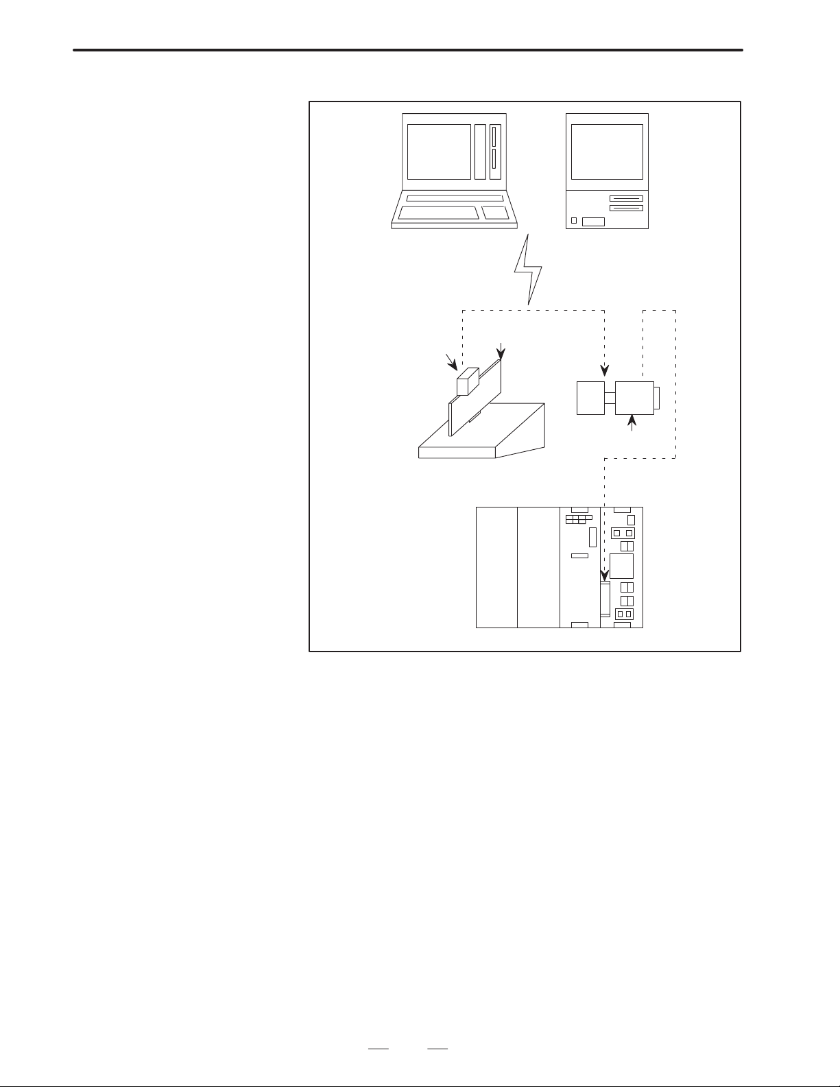
3.1
INTERFACE WITH
USER PROGRAM
AND EXECUTION
MACRO IN P–CODE
PROGRAM
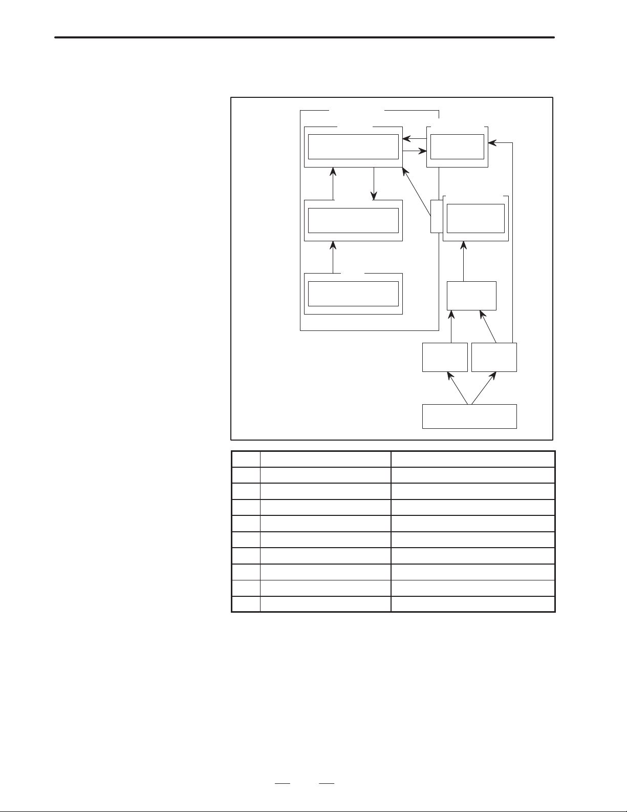
Only a registered P–CODE program cannot be executed. It is called from
the user program by G, M, T code, or specified code by parameter setting,
and executed. In case of macro call, argument designation is possible, and
it is compared as a local variable at the P–CODE (execution macro) side.
Further, for the specification method for the argument, in the same manner
as the normal NC macro, there are possible 2 types of specification
methods, argument specification I, argument specification II, or a
mixture of argument specification I and II. Regarding argument
specification I and argument specification II, refer to FANUC Series
OPERATOR’S MANUAL (macro call command). Moreover , if a minus
value is set at parameter as for macro call by G code, modal call of
P–CODE program can be done by corresponding G code.
User program
(Program edit memory)
O0001 ;
G92X0Y0 ;
G00X100. Y100. ;
G101
<Argument>
G–CODE call
M–CODE call
T–CODE call
S–CODE call
B–CODE call
P–CODE program inside
macro ROM cassette
(execution macro)
O9010 ;
#100=#100+10 ;
M99 ;
3.1.1
Call Code and Program
No.
Call code Call mode
T Subprogram call 9000 #149 TCAL (No. 8508#2)
M Subprogram call 9001–9003 Unused No. 8510–8512
S Subprogram call 9029 #147 SCAL (No. 8508#3)
(Second miscella-
B
neous function code)
G Macro call Continuous
Subprogram call 9028 #146 BCAL (No. 8508#5)
call
M02 ;
Parameter
8513 101
To call a P–CODE program from the user program, call with G, M, or T
code as indicated above.)
Called program
number
9010–9019 Unused No. 8513–8522
Variable number in
which the specified
code is stored
Parameter to be spe-
cified
No. 1030
MODC (No. 8509#2)
39
Page 43
3. EXECUTION MACRO
B–62073E–2/03
Call code
M Macro call 9020–9029 Unused No. 8523–8532
Special Subprogram call 9004, 9005 #146, #147 ACL1, ACL2 (No.
Range–designation M Subprogram call 9009 #148 No. 8538, 8539
Range–designation G Macro call Specified in the
T Macro call 9008 #27 TMCC (No. 8502#6)
Call mode
Called program
number
parameter
Variable number in
which the specified
code is stored
Unused No.8546
Parameter to be spe-
cified
8508#0, #1) No. 8544,
8545
No. 8551, 8552
Note
If the system features a SUB–CPU, only programs 9000 to
9999 can be stored and executed as execution macros.
The priorities of calling custom macros by G, M, S, T , and B, and calling
macro executors by G, M, S, T, and B are as follows:
High LowPriority
Calling custom
macros by G, M, S,
T, and B
Calling macro
executors by G, M,
>>>
S, T, and B
Calling macro
executors by special
codes
Calling macro
executors by
M–code with range
specified
Call of each macro, comparison of subprogram call code and program
number to be called is determined by a compile parameter.
(1) The return sequence number definition for returning to the user’s
program
When operational control is returned to the user’s program from
the P–CODE program, control passes to the sequence number of the
user’s program defined by address P.
(2) Macro modal call is enabled by setting a negative value in the
G–CODE parameters (Nos. 8513 to 8522) for macro call. For
example, –11 set in a parameter represents G1 1 for a modal call state.
Whether the modal call state corresponds to G66 or G66.1 depends
on parameter No. 8509, MODC.
The macro modal call function can be used to call a P–CODE program
from a CNC program. The function cannot be used to call a P–CODE
program from a P–CODE program.
G67 is used for modal call cancellation.
For the detailed specifications, refer to the description of macro call
using G–CODEs in the FANUC Series 15 operator’s manual.
Example
When parameter No. 8513=–100, and parameter No. 8509 MODC=0
CNC program
G91 G01 F100. ;
40
Page 44

B–62073E–2/03
G100 ; Modal call state ON
X10.; Calls O9010 after move.
X10.; Calls O9010 after move.
G90; Does not call O9010.
Y20.; Calls O9010 after move.
G67; Modal call state OFF
P–CODE program
09010;
Z5.;
Z–5.;
M99;
3. EXECUTION MACRO
Notes
1 No P–CODE program can be called from a P–CODE
program in the modal call mode.
2 In the modal call state, no P–CODE program can be called
in the macro call or subprogram call mode.
(3) Subprogram call using special codes
By setting character codes (decimal notation of ASCII codes) to the
parameters (No. 8544,8545), the P–CODE program (09004, 09005)
corresponding to the address can be called as a subprogram. The
defined integer will be stored as a parameter to the macro variable
(#146, #147). The actual use of this function is decided by specifying
the appropiate parameter (No.8508 ACL1 ACL2).
Example
When parameter
No. 8508, ACL1=1
No. 8544=66
User program
O0001 ;
:
G00 X123. B100. ;
:
M02 ;
P–CODE program
O9004 ;(#146=100.)
Notes
1 Addresses that can be specified are all the addresses with
the exception of those used by G, O, N, P. L, and the axis.
2 When program calls such as G65, M98, T code are specified
in the same block, G65, etc. has priority.
(4) M code subprogram call specified range M code
Sub program call of the ”9009” P–CODE program can be performed
by specifying the M–CODE of the range specified by parameter No.
8538, 8539. At this time, the commanded M code is stored as an
argument in macro variable #148.
41
Page 45

3. EXECUTION MACRO
B–62073E–2/03
Example
When parameter
No. 8538=50
No. 8539=60
M50–M60 become the M codes to call “09009”.
Notes
1 When parameter No. 8538 is 0, this processing cannot be
performed.
2 When the value of parameter No. 8538 is specified as
greater than the value of 8539, it will not operate correctly.
3 Special M codes M00, M01, M02, M30, M99 cannot be used
even they are inside the range.
4 When program calls such as G65, M98, T code are specified
in the same block, G65, etc. has priority.
(5) Subprogram call (O9000) by T–code
By setting the parameter (No. 8508, TCAL), a T–code can be used to
call the P–CODE program (O9000) as a subprogram. At this time,
a specified numeric value is stored as an argument in the macro
variable (#149).
The program check screen displays a T–code, but TF and T–codes are
not transmitted.
(6) Subprogram call (O9029) by S–code
By setting the parameter (No. 8508, SCAL), an S–code can be used
to call the P–CODE program (O9029) as a sub–program. At this
time, a specified numeric value is stored as an argument in the macro
variable (#147).
The program check screen displays an S–code, but SF and S–codes
are not transmitted.
(7) Subprogram call (O9028) by B–code (second auxiliary function
code)
By setting the parameter (No. 8508, BCAL), a second auxiliary
function code (set in parameter No. 1030) can be used to call the
P–CODE program (O9028) as a subprogram. At this time, a specified
numeric value is stored as an argument in the macro variable (#146).
The program check screen displays a second auxiliary function code,
but BF and second auxiliary function codes are not transmitted.
(8) Subprogram call by M code
(O9001 – O9003)
By commanding designated M codes, the P–CODE programs
”O9001 – O9003” registered to the ROM can be called for
subprograms. All the local variables are < Blank >.
N_ _ G_ _ X_ _ Y _ _ M<mm>;
(9) Macro call by G code (O9010 – O9019)
By commanding designated G codes, the programs ”O9010–O9019”
registered to the ROM can be called to macro.
Local variables without argument designation are <Blank>.
N_ _ G <gg> Argument designation>;
42
Page 46

B–62073E–2/03
3.1.2
Variables
(10)Macro call by M code (O9020 – O9029)
By commanding designated M codes, the P–CODE programs
”O9020 – O9029” can be called by macro.
Local variables without argument designation will become <Blank>.
N_ _ M <mm> Argument designation>;
(1) P–CODE local variables for automatic operation (#1–#33)
The local variable to be used by the automatic operation P–CODE
program is the same as the local variable to be used by the normal NC
macro.
(2) P–CODE common variable for automatic operation
(#100–#199, #500–#999)
Whether the common variable to be used by the P–CODE program
is the same as that used by the normal NC macro or whether it is
different can be selected by parameter (No. 8503).
Further, when it is a different one, the common variable for the
P–CODE program can be displayed after the normal macro variable
by setting the parameter (No. 8502 #1 or No. 8502 #4).
3. EXECUTION MACRO
3.1.3
Argument Designation
Argument specification is possible in the case of macro call. It can be
referred to as a local variable on the P–CODE program side.
For the specification method for the argument, in the same manner as the
normal NC macro, there are possible 2 types of specification methods,
argument specification I, argument specification II, or a mixture of
argument specification I and II.
Regarding detailed specifications, refer to the FANUC Series 15
OPERATOR’S MANUAL (macro call command).
43
Page 47

3. EXECUTION MACRO
B–62073E–2/03
3.2
LIMITATION FOR EXECUTION MACRO
3.2.1
Argument Specification
3.2.2
Macro call
3.2.3
Variable
Source program for registration custom macro (P–CODE program) is
programmed by the Custom macro used for F ANUC Series 15. But, there
are some limits for execution in Series 15. The P–CODE program custom
macro is described below.
Argument specification is same as in Custom macro used for Series 15.
Macro of P–CODE program call P–CODE program is executed with
“G65” as same as in Custom macro used for Series 15.
G65 P (Program No.) L (Number of repetition) ;
<Argument specification> ;
Expression, argument, etc. of variables are the same as those of Custom
macro used for Series 15.
Note
The local variable to be used by the P–CODE program and
the local variable to be used by the user program are the
same, but note that for the common variable, whether it is
the same or different can be selected by the parameter.
Further, the conversational macro special variables
(#30000–, #40000–) can also be used.
3.2.4
Custom Macro Commands
3.2.5
NC Commands Which Cannot be Used in Automatic Operation
3.2.6
Modal Call from Execution Macro
All the custom macro commands which can be commanded in normal
automatic operations can be used. Further, the custom macro commands
which can handle files can be used.
The following kinds of commands, NC commands necessary for
pre–reading or editing the program must not be used.
Complex type canned cycle
Optional angle chamfering/corner R
Diagram dimensions direct input
Custom macro interruption
Override playback
Modal call cannot be made.
44
Page 48

B–62073E–2/03
3. EXECUTION MACRO
3.2.7
Calling a P–CODE
Program from an
Execution Macro Using
the G, M, S, T, or B
User Code
3.2.8
Calling a User Program
Using an Execution
Macro
Because a P–CODE program is called using a user G, M, S, T , or B code,
the following is inhibited: calling of a user G code during a P–CODE call
by a user G code, and the calling of a user M code, S code, T code, B code,
M codes specifying a range, or a specific code during a P–CODE call by
a user M code, S code, T code, B code, M codes specifying a range, or by
a specific code.
The PGMP bit of parameter 8509 sets whether to permit the following:
calling of a user M code, S code, T code, B code, M codes specifying a
range, or a specific code during a P–CODE call by a user G code, and the
calling of a user G code during a P–CODE call by a user M code, S code,
T code, B code, M codes specifying a range, or by a specific code.
After a P–CODE program (execution macro program) is called from a
user program, another user program can be called as a subprogram by
using the M code specified in parameter No.8533 of the execution macro
program.
[User program]
O0001;
G100 X10. Z20. ;
M30 ;
O1000 ;
:
M99 ;
[P–CODE program]
O9010 ;
:
Mmm P1000 ;
:
M99 ;
3.2.9
Specifying of the G
Code for Macro Calls
of P–CODE Programs
Call format)
Mmm Ppppp;
where,
mm: M code specified in parameter No.8533
pppp: Number of the user program to be called
Notes
1 Another P–CODE program (execution macro program)
cannot be called from the called user program.
2 The sequence number cannot be specified when returning
from the called user program.
A specified range of programs can be called at a time by specifying the
G code corresponding to the first program to be called in parameter
No.8551, the program number of the first program to be called in
parameter No.8552, and the total number of programs to be called in
parameter No.8546. The specified number of programs are called in the
order of the G codes and corresponding program numbers, starting with
the first specified program.
45
Page 49
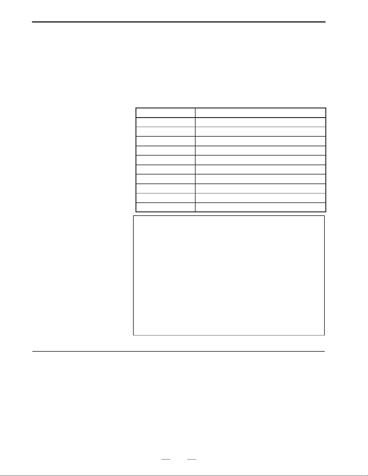
3. EXECUTION MACRO
B–62073E–2/03
The specifiable G code range is 1 to 9999, and the specifiable program
number range is 9000 to 9999. Up to 40 programs can be called at a time.
Example
Parameter No.8546 : 10
No.8551 : 1000
No.8552 : 9500
When the parameters are set as shown above, the correspondence between
the G codes and program numbers is as follows:
G code Corresponding program number
G1000 O9500
G1001 O9501
G1002 O9502
G1003 O9503
G1004 O9504
G1005 O9505
G1006 O9506
G1007 O9507
G1008 O9508
G1009 O9509
Note
For each parameter, the action taken when a value outside
the specifiable range is specified is as follows.
Parameter No.8546:
If zero on a negative value is specified, the program call
is not activated. Even when a value larger than 40 is
specified, only 40 programs are called.
Parameter No.8551:
Values outside the specifiable range are ignored (the
program call is not activated).
Parameter No.8552:
Values outside the specifiable range are a any
out–of–range value is ignored (the program call is not
activated).
3.2.10
Calling a Macro Using
a T Code
By setting compile parameter TMCC (No.8502) to 1, P–CODE program
No. 9008 is called by specifying a T code in a user program.
All addresses specified in this block are used as arguments except that the
T code is transferred to #27, values for address P and L are transferred to
#16 and #12, respectively . Also G codes are transferred to variables #28
to #32 for each group.
Be sure that addresses shall be those available for CNC and the significant
digits are those specified by the CNC.
46
Page 50

B–62073E–2/03
Variable Data to be transferred
#1–#26 Address data for each variable
#27 T code
#28 G code
#29 G code
#30 G code
#31 G code
#32 G code
3. EXECUTION MACRO
Example
3.2.11
Macro and Subprogram Multiplexity in Execution Macro
G91G28X123.45678T5678:
#24=123.456
#27=5678.0
#28=28.0
#29=91.0
Other variables = < vacant >
Note
The L specified in the same block as the T code does not
indicate the number of times that the T code macro call is
repeated.
Separately from the user program multiplexity , 4–stack nesting of macro
program, and 4–stack nesting of subprogram are possible on the
execution macro.
47
Page 51

3. EXECUTION MACRO
3.3
DISPLAYING AND SETTING VARIABLES
B–62073E–2/03
3.3.1
User Program
Common Variables
(#100–#199,
#500–#999)
3.3.2
P–CODE Program
Common Variable
(#100–#199,
#500–#999)
3.3.3
P–CODE Program
Local Variable
(#1–#33)
In the user program, creation and execution of Series 15 custom macro
format custom macros can be performed as a standard. Common
variables can also be displayed and set as a standard on the common
variable screen.
The common variables used by P–CODE program can be selected by
parameter (No.8503) as to whether they are the same or different as those
used normally by NC macro.
When the common variables are set as different ones they can be
displayed after the normal custom macro variables by setting parameter
(No. 8502 #1).
The local variables used by the P–CODE program are the same as those
normally by custom macros in execution macros, but in conversational
macros the local variables used are different from those used normally
used in custom macros. Further, the conversational macro local variables
can be displayed after the local variables used by normal custom macros
by setting parameter No. 8502.
3.3.4
Variable Name Setting (SETVN)
SETVN used for setting a variable number cannot be used with a
P–CODE.
48
Page 52

B–62073E–2/03
3. EXECUTION MACRO
3.4
CAUTIONS
(1) Separate compiler of a program cannot be made. Register the whole
program to the edit memory, and then to the ROM. Max. 400
programs can be registered to the ROM.
(2) In one program, limit the sequence number used for branch
destination (GOTO) to 99. Program end is “M99;”.
(3) One block can accept designation of only one sequence number.
Except the program No. and the optional block skip, designate a
sequence No. at the block head.
49
Page 53

4. CONVERSATIONAL MACRO FUNCTION
CONVERSATIONAL MACRO FUNCTION
4
B–62073E–2/03
4.1
OVERVIEW
The conversational macro function is the function to independently
execute the compiled macro program by the P–CODE program compiler
and the normal NC part program operation.
This function is executed at a lower level than automatic operation
processing. Further, this function is unrelated to such as whether there are
basic operation modes or whether or not it is during automatic operation.
Therefore, the conversational macro function operates independently in
parallel to the NC part program even during automatic operation.
The following functions can be realized by the conversational macro.
Read/write of macro variable (local variable, common variable,
system variable)
Macro command
Screen display (character screen, graphic screen)
Reading of keys
Reading of NC parameters
Read/write of files
Other conversational macro exclusive functions
There are also other auxiliary macro functions as conversational macro
functions. These functions are executed at an execution level the same
as the conversational macro function.
The following functions can be executed in this function.
Macro command (definition of variable, replacement, addition type
calculation, branching, repetition)
Read/write of common variables (#100–#199)
Startup of conversational macro body
Simple call (G65, M98)
Read/write of P–CODE exclusive variables
Data reading of A/D converter
Conversational window function
Reading of relative coordinates
Reading of cutting time and cutting distance, and preset
Torque limit override control
RS–232–C control
Note
The conversational macro function and the execution of the
auxiliary macro function are processed at a lower level than
the NC operation processing. Therefore, the execution of
the conversational macro function is not influenced by the
processing speed of the NC operation, but it is that the
conversational macro and the auxiliary macro processing
speeds will be slowed down during NC operation.
50
Page 54

B–62073E–2/03
4.CONVERSATIONAL MACRO FUNCTION
If both the auxiliary and conversational macro functions have been
specified, the following operations are performed:
1) Conversational macro screen
Conversational and auxiliary macros are alternately executed, in this
order.
2) Other than conversational macro scree
Only auxiliary macros are executed.
The conversational macro function is available to use with MMC–II.
All the custom macro formats of Series 15 are described in the macro
format of the conversational macro program. Further, all the system
variables which can be referred to by the P–CODE program and the
common variables can all be read and written. However, there is no
function to refer to local variables held by the NC. (However,
conversational macro function exclusive local variables have been
provided.)
51
Page 55

4. CONVERSATIONAL MACRO FUNCTION
B–62073E–2/03
4.2
CONVERSATIONAL MACRO FUNCTION
The execution of the conversational macro function is processed
internally at a lower level than the automatic operation processing.
Therefore, the execution of the conversational macro function is not
influenced by the processing speed of the automatic operation. However,
it is possible that the conversational macro function processing speed will
be slowed down during automatic operation. Because of this, there is no
guarantee that the conversational macro body must periodically be
executed.
The following functions can be executed at this level.
Macro call instructions (all macro call instructions which can be
commanded in automatic operation)
Read/write of macro variable (local variable, common variable,
system variable)
Reading of NC parameters
Reading of keys
Screen display (character screen, graphic screen)
Read/write of files
Other conversational macro exclusive functions
Normal NC format cannot be executed in conversational macro program
NC format. It is ignored if commanded. Further, note that in the
conversational macro program NC format the meaning of addresses and
method of use is different from in the normal NC format.
The conversational macro screen to be started up by the conversational
macro progam is under the same control as other screens (POS screen,
etc.). Because of this the conversational macro screen must be finished
to switch to other screens. The timing of this finishing is decided when
M99 of the main program is executed. Note that if the conversational
macro program is a program like the following bad example, switching
to other screens will not be possible and the hangup state will occur.
Bad example Good example
O1234 ;
NO
Key input?
YES
Key input processing
M99 ;
Key input processing
O1234 ;
Key input?
YES
M99 ;
NO
For the conversational macro program, perform programming such that
it becomes a cyclic program to return to sequence number specified by
head of main program or M99 Pp, after executing M99 like the PMC
ladder program.
By means of the above, avoid programming in which the branch
destination goes in the reverse direction by GOTO.
52
Page 56

B–62073E–2/03
4.CONVERSATIONAL MACRO FUNCTION
(1) Starting up conversational macro program
Conversational macros can be executed by pressing the TALK
MACRO soft key or when activated by an auxiliary or execution
macro.
The program to be started up is the program number of the value of
the conversational macro execution control variable 1 (#8500). The
value of the conversational macro execution control variable 1
(#8500) when turning on the power is set by parameter (No.8536).
However, when the parameter (No.8536) is ”0”, the conversational
macro body cannot be started up.
If a conversational macro program having a program number
specified with conversational macro execution control variable
#8500 has not been compiled, the conversational macro function
executes no program resulting in a PS11 ‘3 IMPROPER
NC–ADDRESS alarm.
(2) Stopping the conversational macro
The conversational macro cannot be stopped by such as reset, single
block, feed hold. However, the conversational macro can be stopped
by either setting the parameter (No.8536) to ”0” or by setting the
conversational macro execution control variable 1 (#8500) to 0.
Further, it is possible to end the display of the conversational macro
screen and return to the screen which was displayed before selecting
the conversational macro screen by pressing the software key on the
left edge.
53
Page 57

4. CONVERSATIONAL MACRO FUNCTION
B–62073E–2/03
4.3
AUXILIARY MACRO FUNCTION
The auxiliary macro function is executed at an execution level the same
as the conversational macro function.
The following functions can be executed in this function.
Macro command (definition of variable, replacement, addition type
calculation, branching, repetition)
Read/write of common variables
Startup of conversational macro body
Simple call (G65, M98)
Read/write of P–CODE exclusive variables
Data reading of A/D converter
Conversational window function
Reading of relative coordinates
Reading of cutting time and cutting distance, and preset
Torque limit override control
RS–232–C control
(1) Starting up the auxiliary macro program
The auxiliary macro program to be started up is the program number
of the value of the conversational macro execution control variable
2 (#8600). The value of the conversational macro execution control
variable 2 (#8600) when turning on the power is set by parameter
(No.8537). However, when the parameter (No.8537) is ”0”, the
auxiliary macro program cannot be started up.
(2) Stopping the auxiliary macro program
The auxiliary macro program cannot be stopped by such as reset,
single block, feed hold. However, the auxiliary macro program can
be stopped by either setting the parameter (No.8537) to ”0” or by
setting the conversational macro execution control variable 2 (#8600)
to 0.
(3) Setting the auxiliary macro execution cycle
The auxiliary macro executes one block of a P–CODE program
approximately every 32 ms. This execution cycle can be changed
using parameter No.7045, thus enabling faster execution of the
auxiliary macro.
Note
The faster the auxiliary macro executes the program, the
longer it takes for the program to be displayed on the CNC
screen.
Address
79045 Auxiliary macro execution cycle
Parameter input
Data format : Byte type
Data range : 0 to 20
The parameter value N indicates the number of blocks (N+1) that can be
executed every 32 ms. Examples follow.
N = 0: Approx. 32 ms per a block
N = 1: Approx. 32 ms per two blocks
N = 2: Approx. 32 ms per three blocks
:
54
Page 58

B–62073E–2/03
4.CONVERSATIONAL MACRO FUNCTION
The larger the value of N, the longer the delay in displaying the program
on the CNC screen.
(4) Note
In an auxiliary macro program, do not write data into system common
variables (custom–macro common variables) frequently. Read
common variables once, then write data into them as required.
Alternatively , use variables dedicated to the macro compiler (P–code
exclusive variables) to write data into the common variables when it
is necessary to write data into the variables frequently.
This note also applies to data write (output to the UO signal) to system
variables No. 1100 to No. 1135.
55
Page 59

4. CONVERSATIONAL MACRO FUNCTION
4.4
COORDINATE SYSTEM SCREEN
B–62073E–2/03
4.4.1
Character Coordinate System
In the conversational macro function the coordinate system using
character display and cursor display is called the character coordinate
system. The character coordinate system sets left/right direction as X
coordinate and up/down direction as Y coordinate. In the 9”CRT, the X
coordinate is 0 to 39 from left to right, and Y coordinate is 0 to 16 from
top to bottom; in the 14” CRT, X coordinate is 0 to 73 from left to right
and Y coordinate is 0 to 26 from top to bottom.
Further, display commands which exceed these ranges are ignored. 1 unit
is 1 character. However, the following sections cannot be displayed
because they are used by the system. In 9” CRT, the 0 line ON display
line, 12th line warning message line, 13, 14th line data input line, 15th
status display line sections; in the 14” CRT 0, lst ON display line, 21st
warning message line, 22nd data input line, 23rd status display line, 24th,
25th, 26th line software key frame sections.
Note
It is possible to write to a location to be used by system, but
once a character is displayed when set to a different screen,
there are cases that the character remains on the screen.
(Example)9ICRT
ON display line
0
1
2
3
4
5
6
7
8
9
10
11
12
13
14
MEM
15
POSiITON PROGRAM OFFSET PRG–CHK CHAPTER+
16
0 1 2 3
0123456789012345678901234567890123456789
* * *
STOP
* * * * * * *
* * *
00000 N0000
Software key display line
Status display line
Data input display line
Warning message display line
(1) Mask of O, N Number Display in Conversational Macro Screen
The conversational macro screen can be set such as not to display O,
N number.
If parameter number 8508 ONMSK=1 is set, O,N number is not
displayed.
56
Page 60

B–62073E–2/03
4.CONVERSATIONAL MACRO FUNCTION
(2) Mask of Status Display on Conversational Macro Screen
The status display (mode and status) on the conversational macro
screen can be masked using parameter STDM (No.8507#3).
4.4.2
Graphic Coordinate System
In conversational macro function, the coordinate system using a graphic
display is called graphic coordinate system. The graphic coordinate
system sets left/right direction as X coordinate and up/down direction as
Y coordinate. The X coordinate is –297 to 297 from left to right, and the
Y coordinate is –216 to 216 from top to bottom. Namely , the screen center
becomes (X, Y) = (0, 0). Further, display commands which exceed the
range –32767 to 32767 are clamped by minimum and maximum values.
14” CRT dot coordinate system
215
X
–295
–216
9” CRT dot coordinate system
196
295
–320
X
320
–195
57
Page 61

4. CONVERSATIONAL MACRO FUNCTION
B–62073E–2/03
4.5
VARIABLE,
(1) V ariables which can be used in the conversational macro function are
All the Series 15 system variables and the following.
FUNCTION AND
CONTROL CODE
Variable
number
Macro variables
#1 – #33 Local variables (different function for conversational
and execution macros)
#1 – #99 Referencing a variable as an array R/W f f ×
#100 – #199 Common variables (not battery–powered) R/W f f f
#500 – #999 Common variables (battery–powered) R/W f f f
#30000 – P–CODE variables R/W f f f
#40000 – Expanded P–CODE variables R/W f f f
#99100 – System common variables R/W f f f
Execution control
#8500 Conversational–macro execution–control variable 1 R/W f f f
#8510 Conversational–macro activation–control variable 1 /W f f f
#8600 Conversational–macro execution–control variable 2 R/W f f f
Screen control
#8509 Character–string input program control variable R/W f f ×
#8530 Function–screen control variable R/W f f ×
Key/data input control
#8501 Command–key input variable R/ f × ×
#8502 Data input control variable R/W f × ×
#8503 Numerical–data variable R/ f × ×
#8504 Address–data variable R/ f × ×
#8550 Character–string input R/ f × ×
Expanded key/data input control
#8552 Setting a variable number R/W f × ×
Array processing for P–CODE variables
#8511 Source data R/W f f ×
#8512 Two–dimensional array number at transfer source R/W f f ×
#8513 Three–dimensional array number at transfer source R/W f f ×
#8514 Two–dimensional array number at transfer destination R/W f f ×
#8515 Three–dimensional array number at transfer destination R/W f f ×
Array reference for P–CODE variables
#8512 Two–dimensional array number R/W f f ×
#8513 Three–dimensional array number R/W f f ×
#8516 Number of elements in a one–dimensional array R/W f f ×
#8517 Number of elements in a two–dimensional array R/W f f ×
#8518 (Always set to 1) R/W f f ×
#8519 Number of the first variable in an array R/W f f ×
Function R/W
R/W f × f
Conver
sational
macro
Auxiliary
macro
Execution
macro
58
Page 62

B–62073E–2/03
4.CONVERSATIONAL MACRO FUNCTION
Variable
number
CNC–program reference/write
#8520 Designating a program number R/W f f ×
#8521 Designating a block number R/W f f ×
#8522 Designating the number of a variable to be stored R/W f f ×
#8523 Variable number specifying the number of decimal
places
#8529 Completion code R/ f f ×
Read/preset of machining time and machined distance
#8553 Read/preset of machining time R/W f f ×
#8554 Read/preset of machined distance R/W f f ×
PMC–axis control
#8602 Selecting PMC control axes R/W f f ×
Line control
#8539 Completion code R/ f f ×
T orque–limit override
#8990 Selecting read or write /W f f ×
#8991 Axis number /W f f ×
#8992 Torque–limit override R/W f f ×
#8995 Completion code R/ f f ×
A/D conversion data input
#8996 Completion code R/ f f ×
#8997 A/D converter selection code /W f f ×
#8998 Connector number R/W f f ×
#8999 A/D conversion data R/W f f ×
Window function
#8996 Completion code R/ f f ×
#8997 Alarm information selection code /W f f ×
#8998 Axis number R/W f f ×
#8999 Alarm information R/W f f ×
Relative–coordinate read
#8996 Completion code R/ f f ×
#8997 Selection code for relative–coordinate read /W f f ×
#8998 Axis number R/W f f ×
#8999 Relative coordinates R/W f f ×
Remaining travel–distance read
#5181–#5195 Variables for reading remaining travel distance R/ f f ×
Reading part–program information
#8526 Reading the state of background editing R/ f f ×
#8527 Reading the number of stored programs R/ f f ×
#8528 Reading the capacity of the unused CNC program area R/ f f ×
R/WFunction
R/W f f ×
Conver
sational
macro
Auxiliary
macro
Execution
macro
R: Read enable, W: Write enable, f: Available, X: Not available)
59
Page 63
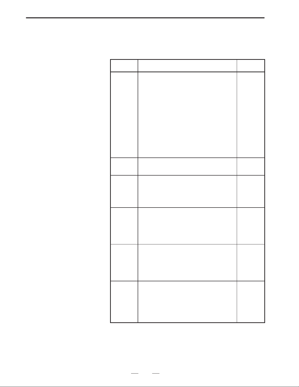
4. CONVERSATIONAL MACRO FUNCTION
(2) Functions which can be used in the conversational macro functions
are all the Series 15 custom macro functions and address functions.
(3) Control codes which can be used in the conversational macro
functions are the following.
B–62073E–2/03
Control
code
G230
G202
G240
G242
G243
G244
G280
G301
G302
G303
G390
G391
G392
G31 1
G300
G320
G321
G65
M98
M99
G330
G331
G335
G336
G337
G338
FGEN
FDEL
FOPEN
FCLOS
FREAD
FWRIT
FPSET
G370
G371
G375
G376
G377
G328
G329
G315 Commanding for arrangement processing Arrange-
Cursor display
Screen deletion
Color specification
Drawing start point setting
Character display
Drawing line type specification
Prompt character display
Linear drawing
Circular drawing (clockwise)
Circular drawing (counter clockwise)
Absolute mode specification
Incremental mode specification
Work coordinate system specification
Rapid traverse speed specification
Rapid traverse drawing
Closed area painting
Marking
Conversational macro program macro call
Conversational macro program subprogram call
Conversational macro program end
Circuit open
Circuit close
1 byte read
Data transmission
Macro variable data input
Macro variable data output
Creating files
Deleting files
Opening files
Closing files
Reading files
Writing files
Setting file pointer
Registering new programs
Deleting programs
Reading specified programs
Writing blocks
Deleting blocks
Reading character type blocks
Writing character type blocks
Meaning of code Function
Screen
display
control
code
Execution
control
code
RS232C
control
code
File
control
code
Referring/
writing
CNC
programs
ment type
processing
of conversational
macro
exclusive
variable
60
Page 64

B–62073E–2/03
4.CONVERSATIONAL MACRO FUNCTION
4.5.1
System Variable
Control
code
G340
G341
G344
G345
G346
G348
G349
G350
G351
G360 Preset of relative coordinate value Relative
G310 Reading PMC address PMC
Rapid traverse command
Cutting feed command
Dwell command
Reference point return command
Auxiliary function command
Status signal reading command
Command signal writing command
Positioning device coordinate system
changing override
FunctionMeaning of code
PMC axis
control
coordinate
system
preset
address
control
All the system variables which can be used by Series 15 custom macro
can be used except for the following system variables. For details of
system variables, refer to the FANUC Series 15 OPERATOR’S
MANUAL.
(System variables which cannot be used)
Alarm message display by #3000
(Alarm number can be displayed)
4.5.2
P–CODE Program
Exclusive Local
V ariables
4.5.3
Conversational Macro
P–CODE Common
V ariables
The local variables to be used by the conversational macro function
P–CODE program are different from the normal local variables to be used
by normal NC macro. This local variable can be displayed after normal
macro variables by setting parameter (No. 8502 #1, #4).
In the auxiliary conversational macro function P–CODE program local
variables cannot be used.
Note
Local variables are enabled only in the various
programmes. If program end is executed by M99 is
initialized.
Common variables to be used by conversa–tional macro P–CODE
program can be selected by parameter (No. 8503) as to whether they are
the same or different as those used by normal NC macro. However, these
common variables are the same as common variables used by automatic
operation P–CODE macro. Further, these common variables can be
displayed after normal macro variables by setting parameter (No. 8502#1
and No. 8502#4).
61
Page 65

4. CONVERSATIONAL MACRO FUNCTION
B–62073E–2/03
4.5.4
UI and UO Signal
Separation for User
and P–CODE Programs
The user program and the P–CODE program can use different signals for
the system variables (UI: #1000 to #1015, #1032, UO: #11 10 to #1115,
#1132).
How to set the parameter:
When EUIO of parameter No.8502 is set to 1, the interface signals listed
in the tables below are used for reading and writing the system variables
of the P–CODE program (execution, conversational and auxiliary
macros).
The status of the following interface signals can be learned by reading
system variables #1000 to #1015 and #1032.
System variable Point Interface input signal
#1000
#1001
#1002
#1003
#1004
#1005
#1006
#1007
#1008
#1009
#1010
#1011
#1012
#1013
#1014
#1015
#1032
16
1
1
1
1
1
1
1
1
1
1
1
1
1
1
1
1
EUI00
EUI01
EUI02
EUI03
EUI04
EUI05
EUI06
EUI07
EUI08
EUI09
EUI10
EUI1 1
EUI12
EUI13
EUI14
EUI15
EUI00–EUI15
The following interface signals can be read and written using system
variables #1100 to #1115 and #1132.
System variable Point Interface input signal
#1 100
#1 101
#1 102
#1 103
#1 104
#1 105
#1 106
#1 107
#1 108
#1 109
#1 110
#1111
#1 112
#1 113
#1 114
#1 115
#1 132
16
1
1
1
1
1
1
1
1
1
1
1
1
1
1
1
1
EUO00
EUO01
EUO02
EUO03
EUO04
EUO05
EUO06
EUO07
EUO08
EUO09
EUO10
EUO11
EUO12
EUO13
EUO14
EUO15
EUO00–EUO15
Note
The UI and UO signals used for user programs (programs
other than the P–CODE program) are the same interface
signals as conventionally used.
62
Page 66

B–62073E–2/03
4.CONVERSATIONAL MACRO FUNCTION
4.5.5
Conversational Macro
Special Variables
(#30000–)
Example
Conversational macro special variables can be used with a P–CODE
program.
An arbitrary number of conversational macro special variables starting
with #30000 can be used.
To specify the variable format, the parameter (No. 8509, EVF2) allows
the user to select floating–point format as used for general macro
variables or fixed–point format.
Parameter No. 8509
EVF2=0 : Floating–point format
EVF2=1 : Fixed–point format
The usable number of conversational macro special variables is the
number set in parameter No. 8549 multiplied by n. When zero is set in
parameter No. 8549, no conversational macro special variable can be
used.
For floating–point format, n=40
For fixed–point format, n=100.
When EVF2=0 for floating–point format
Parameter No. 8549=1
#30000 to #30039
Parameter No. 8549=2
#30000 to #30079
When EVF2=1 for fixed–point format
Parameter No. 8549=1
#30000 to #30099
Parameter No. 8549=1
#30000 to #30199
Notes
1 When fixed–point format is used, a value from –32768 to +32767 can be set in a conversational
macro special variable. A fractional part, if any, is rounded before the value is stored in
fixed–point format.
If a variable in fixed–point format appears in an expression, the variable is evaluated after being
converted to floating–point format.
2 The maximum number of usable conversational macro special variables depends on the tape
memory size.
When the length of tape memory is 160 m or shorter: Maximum value of parameter
No. 8549=64
When the length of tape memory is 320 m or longer: Maximum value of parameter
No. 8549=100
The length of tape memory corresponding to the value of 1 set in parameter No. 8549 is 0.8 m.
3 The values of conversational macro special variables are preserved even if power is turned of f.
4 If the value of parameter No. 8549 is changed, power needs to be turn on again.
5 Conversational macro special variables are displayed on the macro variable display screen
(SETTING), and can be entered through MDI.
6 When the value of parameter EVF2 is 1(fixed–point format), <Null> can not be used.
63
Page 67

4. CONVERSATIONAL MACRO FUNCTION
B–62073E–2/03
4.5.6
Expanded
Conversational Macro
Exclusive V ariable
(#40000 –)
Example
Expanded conversational macro exclusive variables starting from #40000
can be arbitarily used. This variable can be selected to be floating decimal
point format variable the same as normal macro variable, or to be fixed
decimal point format variable by parameter specification (parameter No.
8509, EVF).
Parameter No. 8509
EVF=0 : Floating decimal point format
EVF=1 : Fixed decimal point format
In the same manner as conversational macro exclusive variables
(#30000–), the n multiple of the numerical value specified by parameter
No. 8550 becomes the number of expanded conversational macro
exclusive variables which can be used. When parameter number 8550 is
0, the expanded conversational macro exclusive variable cannot be used.
For the value of n, n=10 when floating decimal point format, and n=30
when fixed decimal point format.
EVF=0 : When floating decimal point format
Parameter No.8550=1
#40000 to #40009
Parameter No.8550=2
#40000 to #40019
EVF=1 : When fixed decimal point format
Parameter No.8550=1
#40000 to #40029
Parameter No.8550=2
#40000 to #40059
Caution
(1) When fixed decimal point format, the value which can be set to this
variable is –32768 – 32767. The figures after the decimal point are
rounded off and it is memorized in fixed decimal point format.
Further, when the variable in this fixed decimal point format appears
in <format> it is converted to floating decimal point format and
evaluated.
(2) The maximum expanded macro exclusive variables which can be
used depends on the capacity of tape storage memory.
Tape storage memory 80m:
Expanded conversational macro cannot be used
Part program storage memory 160m:
Max. value of parameter No.8550=500
Part program storage memory 320m:
Max. value of parameter No.8550=1000
Part program storage memory more than 640m:
Max. value of parameter No.8550=1970
The relationship between value of parameter 8550 and part program
storage length is as follows.
Approx. 0.2m used for each value 1 of parameter No. 8550.
(3 ) The expanded macro exclusive variable keeps its value even if power
is cut.
(4) If value of parameter No. 8550 is changed, it is necessary to turn on
power again.
64
Page 68

B–62073E–2/03
(5) The expanded macro exclusive variable is displayed on macro
variable display screen (SETTING). Further, input from MDI is
possible.
(6 ) Cannot express <V acant> when paramter EVF=1 is set (fixed decimal
point format).
4.CONVERSATIONAL MACRO FUNCTION
4.5.7
Reference and Writing System Common V ariables
4.5.8
Execution Control
V ariable
Reference and writing of execution macros and conversational macro
programs system common variables by conversational macro programs
can be performed. The number adding 99000 to the variable number you
want to reference corresponds to the system common variable.
#99100 Corresponds to #100
#99149 Corresponds to #149
#99500 Corresponds to #500
#99531 Corresponds to #531
(1) Conversational macro execution control variable 1 (#8500)
If the conversational macro body is started up, it executes the
conversational macro program of the value of #8500 as program
number. However, the value of #8500 when turning on the power is
the value of the parameter (No. 8536).
Control can be transferred to other conversational macro programs by
rewriting the value of #8500. If the value of #8500 is rewritten, after
execution finishes of the currently executing conversational macro
program, the character screen and graphic screen are deleted, and the
conversational macro program of the value of #8500 as program
number is executed. If the value of #8500 is not rewritten, the same
conversational macro program continues to be executed.
At this time, the character screen and graphic screen are not deleted.
(2) Conversational macro start control function 1 (#8501)
The conversational macro body can be started up by setting the
conversational macro start control variable (#8510) to “1”.
The conversational macro body can also be ended by setting the
conversational macro start control variable 1 to “0”.
(3) Conversational macro execution control variable 2
If the conversational execution control macro is started up, it executes
the auxiliary macro program of the value of #8600 as the program
number. However, the value of #8600 when turning on the power is
the value of the parameter (No. 8537).
Control can be transferred to other auxiliary macro programs by
rewriting the value of #8600. If the value of #8600 is rewritten, after
execution finishes of the currently executing auxiliary macro
program, the auxiliary macro program to set the value of #8600 as
program number is executed. If the value of #8600 is not rewritten,
the same auxiliary macro program continues to be executed.
65
Page 69

4. CONVERSATIONAL MACRO FUNCTION
4.5.9
Key Input Control
Variable
(1) Command key input variable (#8501)
Command key input can be read by #8501. The correspondence
between command key input and the value of #8501 is as shown
below. If there is no command input, the value of #8501 is 0.
If there once was command key input, the value of #8501 remains this
value until read by conversational macro command, and subsequent
key input cannot be accepted. If #8501 is read, it enters the state that
key input is accepted and the value of #8501 becomes 0.
Writing a value to #8501 cannot be performed.
PAGE ± :1
PAGE ° :2
CURSOR UP : 3
CURSOR DOWN :4
CURSOR LEFT :5
CURSOR RIGHT : 6
INPUT : 8
RESET : 10
SOFT FUNCTION KEY RIGHT :11
SOFT FUNCTION KEY 1 : 12
SOFT FUNCTION KEY 2 : 13
SOFT FUNCTION KEY 3 : 14
SOFT FUNCTION KEY 4 : 15
SOFT FUNCTION KEY 5 : 16
SOFT FUNCTION KEY 6 : 17
SOFT FUNCTION KEY 7 : 18
SOFT FUNCTION KEY 8 : 19
SOFT FUNCTION KEY 9 : 20
SOFT FUNCTION KEY 10 :21
B–62073E–2/03
Note
CRT14” is SOFT FUNCTION KEY 1–SOFT FUNCTION KEY
10
CRT 9” is SOFT FUNCTION KEY 1–SOFT FUNCTION KEY
5
SOFT FUNCTION KEY LEFT , POS, OFSET, and other keys
used to directly select an NC screen are managed by the
system and cannot be read.
(2) Data input control variable
#8502 : Data input control variable
#8502 : Numerical data variable
#8502 : Address data variable
#8502 : Character variable
Controls input of numerical data and address data by setting the following
value to data input control variable #8502.
#8502= 0 : No data input
= 1 : Inputting numerical data
= 2 : Inputtting address data and numerical data
= 3 : Inputting character row
When #8502 is 0, nothing is displayed to data input line and
data input cannot be performed.
66
Page 70

B–62073E–2/03
4.CONVERSATIONAL MACRO FUNCTION
When #8502 is 1, “NUM” is displayed to data input line and
numerical data input can be performed. The inputted
numerical data can be read by numerical data variable #8503.
When #8502 is 2, first ”ADRS” is displayed to the data input
line, and address data can be inputted. Next, if address data
is inputted ”ADRS ? NUM” (? is inputted address) is
displayed and numerical data can be inputted.
The inputted data can be read by the various address data
variables #8504 and numerical data variables #8503.
when #8502 is 3, nothing is displayed to the data input line.
However, data can be inputted. The inputted data can be read
in the sequence inputted by character variable #8550. The
data to be read is in ASCII code. Further, if it is read until the
end, can be read.
The key input to set a value other than 0 for the command key input
variable (#8501) acts as a trigger and the data input line reterns to initial
state. The inputted numerical value and address can be read by the various
numerical data variables and address data variables. Further, the
numerical data variable and address data variable are kept until
numerically set in data input control variable.
When there is no input of numerical data and address data, the value of
#8503 and #8504 becomes <Vacant>.
The correspondence between the inputted address and #8504 is as shown
below
A ...1 B ...2 C ...3 D ...4 E ...5
F ...6 G ...7 H ...8 I ...9 J ..10
K ..11 L ...12 M ..13 N ..14 O ..15
P ..16 Q ..17 R .. 18 S ..19 T .. 20
U ..21 V ..22 W .. 23 X .. 24 Y .. 25
Z ..26
(3) Conversational macro extension data input control function
If you set 3 for #8502, and a variable number for #8552 to provide,
full key data input mode, and appears < for the input line, and it is
possible to input addresses and number data.
The data input line changes to the initial state on key input to set key
input control variable #8501 to 0. The input number and address can
read for 32 variables from a variable number which is set to variable
#8552 as each ASCII code, data. <blank> input a 32 number series
if there is no input data.
Example:
Set for
#8502=3 ;
#8552=500 ;
and input
0123456ABCD<
and press return key
#500=48
#501=49
#502=50
#503=51
#504=52
#505=53
67
Page 71

4. CONVERSATIONAL MACRO FUNCTION
#506=54
#507=65
#508=66
#509=67
#510=68
#511=<blank>
:
#531=<blank>
#8501=8
B–62073E–2/03
Caution
(1) Until the INPUT key is pressed, the previous value remains for the
contents of macro variable from number specified in #8552. The
INPUT key is pressed and first the value is set.
(2) The value of 8503, 8504 is not guaranteed.
(3) When a macro variable number other than 0 has been set in #8552,
if the INPUT key is pressed this function is unconditionally
performed. In that case, input by #8550 (character variable) cannot
be performed.
(4) Function–screen control variable
V ariable #8530 indicates the function currently displayed on the CNC
screen.
Writing the following data into variable #8530 changes the screen to
the corresponding function screen.
#8530 : 0:Position screen
1:Program screen
2:Offset screen
3:Program check screen
4:Setting screen
5:Service screen
6:Alarm screen
7:Graphic screen (only when the option is used)
8:Conversational macro screen
11:Operation history screen
4.5.10
Character String
Registered Program
Control Variable #8509
Note
If a value other than those described above is written, it is
ignored.
#8509 is the variable command to call the registered character string
program. Refer to Character display (Address P of G243) for detail.
68
Page 72

B–62073E–2/03
4.CONVERSATIONAL MACRO FUNCTION
4.5.1 1
Arrangement Type
Processing of
Conversational Macro
Exclusive V ariable
This is the function to control the processing for arrangement type
variables or one group of variable rows.
1) Clearing arrangement type variables, variable rows (continuous
reading of specified data)
2) Transfer from arrangement type variables, variable rows to variable
row
In each processing, control code ”G315” is commanded after defining the
arrangement, variable row, or data to each of the following control
variables.
#8511 : Transmission origin Data
#8512 : Transmission origin
T wo–dimensional arrangement number or variable row head
variable number
#8513 : Transmission origin
Three–dimensional arrangement number
#8514 : Transmission destination
T wo–dimensional arrangement number or variable row head
variable number
#8515 : Transmission destination
Three–dimensional arrangement number
Control code
G315 P (processing code) K (processing data number) ;
The processing code specifies the contents of the processing by a 3–digit
number. Zero–suppress is possible with the upper rank ”0”
P001 : Stores #8511 data from variable
(P1) specified by #8514 to K con–tinuous variables.
P002 : Transfers K continuous variables
(P2) data from variable specified by #8512, from variable
specified by #8514 to K continuous variables. (Ascending
sequence transfer)
P003 : Transfers K continuous variables
(P3) data from variable specified by #8512, from variable
specified by #8514 to K continuous variables. (Descending
sequence transfer)
P101 : Stores #8511 data from arrangement variable #1 specified by
#8514, #8515 to K continuous arrangement vari–ables.
P102 : Transfers K continuous arrangement variables data from
arrrangement variable specified by #8512, #8513, from
arrangement variable #1 specified by #8514, #8515 to K
continuous arrangement vari–ables. (As–cending sequence
transfer)
69
Page 73

4. CONVERSATIONAL MACRO FUNCTION
B–62073E–2/03
4.5.12
Reference of Arrangement of Conversational Macro Exclusive V ariables
Conversational macro exclusive variables (#30000...) can be referred to
by the two or three–dimensional arrangement types. Set a proper value to
the following arrangement control variables beforehand and the
conversational macro exclusive variable of the arrangement element
corresponding to the variable number (#1 – #99).
Note
#1 to #99 for convesational macro are different from #1 to
#33 local variables for execution macro.
Arrangement control variable
#8512 Two–dimensional arrangement number
#8513 Three–dimensional arrangement number
#8516 One–dimensional arrangement element number
#8517 Two–dimensional arrangement element number
#8518 1 (Note (1))
#8519 Arrangement top variable number
Specify the arrangement type by the arrangement control variables from
#8516 to #8519 beforehand and specify the arrangement number referred
to by the #8512 and #8513 to refer to the variables with #1 to #99.
The correspondence between the conversational macro exclusive
variable and arrangement element is as shown below:
Conversational macro exclusive variable number
= #8519 + ((#8516_#8517)_(#8513–1))
+(#8516_(#8512–1)+(Specified variable number–1)
Example
Notes
1 Set #8518=1 when using #1–#99 as a arrangement type reference variable of the
conversational macro exclusive variable. When #8518=0, an alarm occurs as #1–#33 are local
variables and #34–#99 are unusable variable.
When turning on the power, #8518=0 is set.
2 #8512–#8517=1, #8519=30000 is set for each arrangement control variable when turning on
the power. Because of this, #8513 and #8517 can be used without recognition when used as
a two–dimensional arrangement.
3 For each variable and for the conversational macro variable number after calculation, check
is not performed. When necessary, make it correspond to the macro program.
4 This function is a function that is usable only by the conversational macro program.
When the #8516, #8517, and #8519 are set to 10, 5, and 30100,
respectively:
1. When both of #8512 and #8513 are set to 1, the #1 corresponds
to the #10100.
2. When the #8512 and #8513 are set to 3 and 2, respectively, the
#10 corres–ponds to the #10179.
70
Page 74

B–62073E–2/03
4.5.13
Refer to and Read CNC
Program with
Conversation Macro
(1) Summary
Recording, deleting and changing of NC part program is possible by
the conversation macro function. Control the CNC program with
program number and block number. Count the block number count
in order by each EOB using the block No.1 which is the block of
address “O” of the relevant program. In the converational macro
CNC program, the data of one word is expressed by the address code
and 2 numbers, which are reported to form a block.
Set parameter No.8508, EXT1 to “1” at compiling when using this
function.
Example:
00001 ; Block No.1
G00 X10. ; Block No.2
M03 S1000 ; Block No.3
Program number 0001, block No. 3, storage variable number = 100
#100= 13 Address M
#101= 3 Numerical value
#102= 19 Address S
#103=1000 Numerical value
#104= 27 Address EOB
The control command instructs the G code by the conversational macro.
There is a complete code for checking whether or not the commanded
function has been correctly executed.
After execution of G328, G329, G370 to G377, check the complete code.
System variable
#8520 Program number specification
#8521 Block number specification
#8522 Storage variable number specification
#8523 Number of digits after decimal point specification variable
number
#8526 Status of background editing (reading exclusive)
#8527 The number of registered programs (reading exclusive)
#8528 V acant area of CNC programming memory (reading exclusive)
#8529 Complete code (reading exclusive)
Control code
G370 Registration of new program
G371 Deleting programs
G375 Reading specified blocks
G376 Block writing
G377 Deleting blocks
G328 Reading specified blocks of character type
G329 Writing specified blocks of character type
4.CONVERSATIONAL MACRO FUNCTION
Note
0 is set for #8520 to #8523 when turning on the power.
71
Page 75

4. CONVERSATIONAL MACRO FUNCTION
(2) Recording of a new program
G370 ;
Specify the program number you wish to record and instruct G370 to
you record a new program.
Example:
If you want to record O0002;
#8520=2 ;
G370 ;
IF[#8529 NE 0] GOTO 900 ;
Recording end
N900 ;
Error
Conduct similar processing as the edit “Oxxxx”+“INSRT” when
recording of a new program. EOB is not insegted.
O0002
%
B–62073E–2/03
(3) Deleting a program
G371 ;
Specify the program number that you want delete and instruct G371
when you delete a program.
Example:
If you want to delete O0003
#8520=3 ;
G371 ;
IF[#8529 NE 0] GOTO900 ;
End of deletion
N900 ;
Error
(4) Reading a Specified Block
G375 ;
Specify the program number and block number. As a result, the
relevant block can be read to a specified variable area.
Example:
If
O0004 ;
G92 X0. M08 ;
G90 G00 X10.5 M05 ;
#8520=4 ;
#8521=3 ;
#8522=100 ;
G375 ;
IF[#8529 NE 0] GOTO900 ;
End of reading
N900 ;
72
Page 76

B–62073E–2/03
4.CONVERSATIONAL MACRO FUNCTION
Error
The following program data is housed from #100 which is specified
by housed variable number #8522, if you execure the above described
instruction;
#100=7 Address “G”
#101=90 Number
#102=7 Address “G”
#103=0 Number
#104=24 Address “X”
#105=10.5 Number
#106=13 Address “M”
#107=5 Numbew
#108=27 Address “EOB”
EOR (28) is housed as an address, if EOB is not at the end block of the
program or EOR position is specified with block number.
Reading is not conducted as the end code becomes “255”, if you
specify a block No. in addition to the block of EOR.
Example:
If
O0004 ;
G92 X0. M08 ;
M02
%
#100=13 Address “M”
#101=2 Number
#102=28 Address “EOR”
Example:
If
O0004 ;
G92 X0. M08 ;
%
#100=28 Address “EOR”
(5) Block writing
G376 (Pp) ;
Prepared program data can be written in the variable area after the
block specified by the program number and block number. Specify
the maximum series of variable data by address P. If address “EOR”
is present within the specified data, write to “EOR”; if “EOR” is
present, write to the immediately preceding data; and if neither
“WOR” nor “EOR” is present, write data specified by address “P”.
Example:
If
O0004 ;
G92 X0. M08 ;
G90 G00 X10.5 M05 ;
#8520=4 ;
#8521=2 ;
73
Page 77

4. CONVERSATIONAL MACRO FUNCTION
#8522=100 ;
#100=7 ;
#101=1 ;
#102=24 ;
#103=20.5 ;
#104=6 ;
#105=1000 ;
#106=20.7 ;
G376 P7 ;
IF[#8529 NE 0] GOTO900 ;
End of writing
N900 ;
Error
If you execute the above instruction, a block is input as follows;
O0004 ;
G92 X0. M08 ;
G1 X20.5 F1000. ;
G90 GO X10.5 M05 ;
End code becomes “255” and it is impossible to conduct writing,if the
specification of block number is EOR block only or higher numbers.
However, when writing a program to a program of only a program
number, it becomes possible by setting 0 to the block number.
B–62073E–2/03
(6) Decimal point specification of every address in block writing
The number of digits after under the decimal point of every address
can be specified. With this specification, the contents of the variable
number which was specified to #8523 becomes the number of digits
after the decimal point of address A, and it is possible to determine
the number of digits after the decimal point of every address, as
shown below.
#8523=501 ;
#501 is the number of digits after the decimal point of address A
#502 is the number of digits after the decimal point of address B
:
:
#525 is the number of digits after the decimal point of address Y
#526 is the number of digits after the decimal point of address Z
Specify <blank> or 0–7 for the number of digits after the decimal
point. In the case of <blank>, it is considered that no decimal point
exists in the address.
Example:
If address code=A, number=1.2345678
Decimal point specification
= <blank> A1
= 0 A1.
= 1 A1.2
= 2 A1.23
= 3 A1.235
*
= 4 A1.2346 *
= 5 A1.23457 *
74
Page 78

B–62073E–2/03
4.CONVERSATIONAL MACRO FUNCTION
= 6 A1.234568 *
= 7 A1.2345678
* The data after decimal point specification is rounded off.
When #8523 is 0, least input increment for specified address is set.
(7) Block deletion
G377 ;
Blocks which are specified by a program number and block number
can be deleted.
#8520=4 ;
#8521=3 ;
G377 ;
IF[#8529 NE 0] GOTO900 ;
End of deletion
N900 ;
Error
The block of block No.3 of program O0004 is deleted, if you execute
to the above instruction.
(8) Special cases
A block constructed from a word formed by the combination of
address+number” and EOB is the usual processing unit in this
function described above. Therefore, it is impossible to show the case
of block delete instruction without a number on to conversational at
macro variable as follows. So displays it with a variable.
Specification of block delete
/ M00; #100=29 Address “/”
#101=<blank> Number <blank>
#102=13 Address “M”
#103= 0 Number 0
#104=27 Address “EOB”
(9) Reading the specified character–type block (G328)
This control code converts every character of the specified block to
a decimal ASCII code and puts them into the specified variable area,
even if non–word–type data is specified in the block. Control
commands (WHILE, IF , etc.) and functions (SIN, COS, FUP , etc.) are
represented with special codes.
#8520=Program number ;
#8521=Block number ;
#8522=100 ; (Reading variable number)
G328 ;
IF [#8529 NE 0] GOTO900 ; (Error check)
When the specified block is ”#1=SIN[#2];, the following is read:
#100 : 35 (23H) “#”
#101 : 49 (31H) “1”
#102 : 61 (3DH) “=”
#103 : 276 ( 114H) “SIN”
75
Page 79

4. CONVERSATIONAL MACRO FUNCTION
#104 : 91 (5BH) “[”
#105 : 35 (23H) “#”
#106 : 50 (32H) “2”
#107 : 93 (5DH) “]”
#108 : 59 (3BH) “;”
When a character–type block is read using the word–type block
reading function (G375), completion code 253 is returned to #8529.
If this code is returned, read the specified block again using the
character–type block reading function (G328).
#8520=Program number ;
#8521=Block number ;
#8522=Reading variable number ;
G375 ; (Word–type block reading function)
IF [#8529 EQ 253] GOTO100 ;
:
N100 G328 ;
(10)Writing the specified character–type block (G329)
This control code allows program data to be written to a specified area
in character units even if non–word–type data is specified. First,
define the program data in the macro variable area with ASCII codes.
Then, execute this control code to write it to the specified area.
(Character–type block reading function)
B–62073E–2/03
#8520= Program number ;
#8521= Block number ;
#8522= Number of the first ASCII code string
G329 P10 ;
IF [#8529 NE 0] GOTO900 ; (Error check)
Instructions, such as P that specifies the maximum number of data
items to be written, are used in the same manner as for control code
G376 (writing word–type blocks).
(11)Background Edit Status
The background edit status of the CNC can be read in the form of a
variable by using the conversational or auxiliary macro.
#8526: The background editing is
0:suspended
1:in progress
(12)The Number of Registered Programs
The number of programs registered in the CNC program memory can
be read in the form of a variable by using the conversational or
auxiliary macro.
#8527: The number of registered programs
(13)Free Capacity of CNC Program Memory
The free capacity of the CNC program memory can be read in the
form of a variable by using the conversational or auxiliary macro.
#8528: Free capacity of the CNC program memory
(number of characters)
76
Page 80

B–62073E–2/03
4.CONVERSATIONAL MACRO FUNCTION
(14)End code (#8529)
Check the end code after running every processing.
#8526 Contents
0 Normal Completion
1 Double open has occurred
2 Cannot open because being used by another user
3 Cannot open because program does not exist
4 Attempted to edit program during operate
10 Specified program does not exist (has not been registered)
11 Specified program number already exists (cannot be newly created)
12 No vacant area in tape storage memory
13 No vacant area in directory (over the register number)
15 Attempted to edit language which cannot be edited
16 Attempted to edit program which cannot be edited
100 There is already background editing
101 Data protection key has been set OFF
102 Erroneous program number has been specified
103 Erroneous block number has been specified
104 Address not in address code table existed during editing(
There is not format ”address plus numerical value”)
105 There is an error in macro variable number for editing
253 The specified block is not of word type (address + numeric)
255 Parameter number 8508, EXT1 is 0
(15)Notes
Selection processing by work number search etc. is required in the
case foreground operation of a program which has been prepared and
edited processed with background functions.
(16)Address code table
Address Code Address Code Address Code
A 1 K 11 U 21
B 2 L 12 V 22
C 3 M 13 W 23
D 4 N 14 X 24
E 5 O 15 Y 25
F 6 P 16 Z 26
G 7 Q 17
H 8 R 18 EOB 27
I 9 S 19 EOR 28
J 10 T 20 / 29
77
Page 81

4. CONVERSATIONAL MACRO FUNCTION
(17)Special code list
IF 258 102H
WHILE 259 103H
GOTO 260 104H
DO 261 105H
END 262 106H
GE 264 108H
GT 265 109H
LE 266 10AH
LT 267 10BH
NE 268 10CH
EQ 269 10DH
MOD 270 10EH
THEN 271 10FH
XOR 272 110H
OR 273 111H
AND 274 112H
Instruction Decimal Hexadecimal
B–62073E–2/03
SIN 276 114H
COS 277 115H
TAN 278 116H
ATAN 279 117H
SORT 280 118H
ABS 281 119H
BCD 282 11AH
BIN 283 11BH
FIX 284 11CH
FUP 285 11DH
ROUND 286 11EH
ACOS 287 11FH
ASIN 288 120H
LN 289 121H
EXP 290 122H
POPEN 291 123H
PCLOS 292 124H
DPRNT 293 125H
BPRNT 294 126H
SETVN 295 127H
ADP 296 128H
FGEN 298 12AH
FDEL 299 12BH
FOPEN 300 12CH
FCLOS 301 12DH
FPSET 302 12EH
FREAD 303 12FH
PWRIT 304 130H
78
Page 82

B–62073E–2/03
4.CONVERSATIONAL MACRO FUNCTION
4.5.14
Reading of Cutting
Time and Cutting
Distance by
Conversational
Macro, and Preset
Functions
Cutting distance and cutting time can be read and preset with the macro
variable of the conversational macro.
Use it for the control of a tool life.
(1)Reading and presetting of cutting time (#8553)
Count the time only for instruction of G01 (linear interpolation), G02
(circular interpolation) by #8554.
The unit is the same as the macro variable (#3002).
(2)Reading and presetting of cutting distance (#8554)
Count the distance only for instruction of G01(linear interpolation),
G02, G03 (circular interpolation) by #8554.
The unit is the same as the least input increment of control axis.
Notes
1It is necessary to set
Parameter No. 8508 EXT1=1
Parameter No. 8508 CUTLG=1
in order to use cutting distance reading and preset function.
2As the tool movement distance is added to #8554 at the time
of slot of the cutting block, the distance of block movement
is still added even if cutting stops due to resetting, etc.
4.5.15
PMC Axis Control by Conversational Macro
(3)Caution:
#8553 and #8554 are not set to 0 when turning on the power. The user
himself should manage this.
(1)Overview
Control of PMC control axis can be performed by conversational
macro via the access control interface by PMC.
Axis control is performed by the following nine types of control
codes. Which PMC control axis control is performed is specified by
the PMC control axis selection variable (#8602).
G340Rapid traverse command
G341Cutting feed command
G344Dwell command
G345Reference point return command
G346Auxiliary function command
G348Status signal read command
G349Command signal write command
G350Machine coordinate system positioning
G351Override change
#8602PMC control axis selection variable
*Control axis selection
#8602 Control axis
1 1st axis
2 2nd axis
3 3rd axis
79
Page 83

4. CONVERSATIONAL MACRO FUNCTION
#8602 Control axis
4 4th axis
5 5th axis
6 6th axis
7 7th axis
8 8th axis
B–62073E–2/03
Caution
1) When other than 1–8 is specified to #8602, the control command is
ignored.
2) #8602=0 occurs when turning on the power.
(2) Control code details
1) Rapid traverse command (G340)
G340 Xxxx ;
Performs rapid traverse shift command to PMC control axis. For the
shift amount, incremental shift amount is always commanded by
address X.
2) Cutting feed command (G341)
G341 Xxxx Ffff ;
Performs cutting feed shift command to PMC control axis. For the
shift amount, incremental shift amount is always commanded by
address X. The feed rate is commanded by address F.
3) Dwell command (G344)
G344 Xxxx ;
Performs dwell command to PMC control axis. The dwell amount
is commanded by address X.
4) Reference point return command (G345)
G345 ;
Performs reference point reutrn command to PMC control axis.
5) Auxiliary function command (G346)
G346 Mmm ;
Performs auxiliary function command for PMC control interface.
The auxiliary control code is commanded by address M.
6) Status signal reading command (G348)
G348 Pppp ;
Reads the status signal of the pertinent PMC axis control interface to
the variable number specified by address P.
Bit No.
#7 #6 #5 #4 #3 #2 #1 #0
CNCAx DENx MFnX BUFx
x : PMC control axis number
n : Auxiliary function selection number
. . . . . uses 1 in this function
1. CNCAx (axis control command reading complete signal)
Signal to notify that one block amount of command data of PMC
access control has been stored in the execution wait buffer after
the CNC side has read it.
2. DENx (distribution complete signal)
In the axis control command, the axis becomes LOW during shift
by rapid traverse, cutting feed, reference point return, and device
coordinate system positioning.
80
Page 84

B–62073E–2/03
4.CONVERSATIONAL MACRO FUNCTION
3. MFnX (auxiliary function reading signal)
Auxiliary function command (G346) is executed and becomes
HIGH until auxiliary function complete signal FINX is inputted.
4. BUFx (buffer full notification signal)
Becomes HIGH when axis command block exists in input
register (execution wait buffer).
Example:
When MFX=1, #100=8 is inputted by
G348 P100 ;
7) Command signal writing command G349
G349 Pppp ;
Writes the specified numerical value specified by address P to the
pertinent PMC axis control interface command signal.
#7 #6 #5 #4 #3 #2 #1 #0
PMCAx RSTx STPx SBKx MSBKx FINnX
Bit No.
x : PMC control axis number
n : Auxiliary function selection number
. . . . . uses 1 in this function
1. PMCAx (axis control command read strobe signal)
Requests CNC side to read 1 block of specified data of PMC axis
control.
This signal cannot be written. (Can not be controlled with
conversational macro.)
2. RSTx (reset signal)
Resets axis control by PMC. Simultaneously, disables all the
commands for which buffering is performed.
3. STPx (axis control temporary stop signal)
Stops the axis controlled by PMC. The stopped operation restarts
if this signal is set to LOW.
4. SBKx (block stop signal)
During execution of commands from PMC, if this signal is set to
HIGH, stops axis control when the currently executing block has
finished. If set to LOW, executes the command on which
buffering has been performed.
5. MSBKx (block stop prohibit signal)
SBK becomes enabled when this signal is HIGH.
6. FINnX (auxiliary function complete signal)
If this signal is returned, the auxiliary function ends and proceeds
to the next command block.
This signal cannot be written. (Can not be controlled with
conversational macro.)
Example: when you desire to set RSTx=1
G349 P64
8) Device coordinate system positioning G350
G350 Xxxx ;
Performs positioning command of device coordinate system for PMC
control axis. For the shift amount, commands device coordinate
system absolute position to address X.
9) Override change G351
G351 Pppp ;
Commands override amount applied to PMC control axis cutting feed
in numerical value by address P.
Units are in % and are settable from 0–255%. Kept until the next
81
Page 85
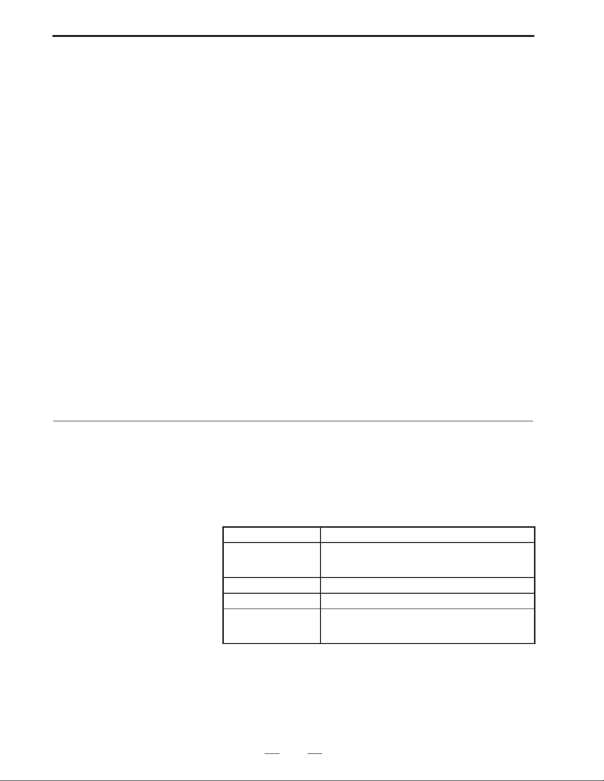
4. CONVERSATIONAL MACRO FUNCTION
change command is performed. It is set to 100% when turning on the
power.
(3 ) Caution
1) Command buffering
Buffering of command block is performed on CNC side in order to
continuously carry out multiple commands in the axis control
function by PMC. Namely, even if one block is being executed, if
there is a vacancy in CNC buffer it is possible to perform the next
command. However, note that when there is no vacancy in CNC
buffer, the previous block command completes until a vacancy occurs
in the buffer because wait state occurs inside the command.
As commands are stored in the buffer when G3** is executed, (1)
PMCAx described on the previous page is not needed.
2) Auxiliary command function
Commanding an auxiliary function is possible by G346, but the
auxiliary function complete signal FINnX cannot be controlled in the
conversational macro. Control it by the PMC.
3) Conflict of axis control functions by original PMC
Never perform commands from both the PMC and this function for
the same PMC controlaxis. For the PMC control axis to be used by
this function, control in the PMC by only the auxiliary function
complete signal ”FINnX”.
4) Data units
Command the shift amount to be commanded by address X (dwell
amount), and feed rate to be commanded by address F in the
minimum setting units.
B–62073E–2/03
4.5.16
Torque Limit Override Control
The specified value of the torque lilmit override can be changed by setting
a value in the range #8990–#8992. Further, reading the torque limit
override value to #8992 by setting a value to #8990, #8991.
#8990: Information I.D.
#8991: Axis number
#8992: Torque limlit override setting value
#8993: Complete code
Macro variable Contents
#8990 Information I.D.
100: Writing torque limit override
101: Reading torque limit override
#8991 Axis number (1–8)
#8992 Torque limit override value (0–255)
#8993 Complete code
0: Normal end
–1: Abnormal end
There is the following relationship between the setting value and the
torque limit override.
Setting value Torque limit override
00%
::
255 100 %
82
Page 86

B–62073E–2/03
4.CONVERSATIONAL MACRO FUNCTION
Notes
1 The torque limit override of each axis becomes 100% when
turning on the power.
2 This function is programmed as an execution macro.
3 When attempting to set a value other than 0–255 to #8992,
that command will be ignored.
4 Enable/disable of the torque limit can be performed by
parameter in G00 mode.
5 Enable/disable of the torque lilmit can be performed by
parameter during acceleration /deceleration.
#7 #6 #5 #4 #3 #2 #1 #0Address
1802 TRQ
Bit No.
TRQ Torque limit override function is
0: Disabled (override 100%)
1: Enabled
#7 #6 #5 #4 #3 #2 #1 #0Address
1803 TQL TQE
TQL Torque limit override function in G00 mode is
0: Enabled
1: Disabled (override 100%)
TQE Torque limit override function during acceleration
/deceleration is.
Note) TQE, TQL are enabled when 1802#TRQ is 1
Address
1882 Allowable range after exponential type acceleration/deceleration
Parameter input
Data format : Word type
Data unit : Detection unit
Data range : 0 to 65535
Judges during acceleration/deceleration by difference of 1ITP of
accumulated amount when parameter 1803#TRQ=1. By this means, it
keeps to the permissable range when in exponential type
acceleration/deceleration.
When in exponential acceleration/deceleration, in order not to make F
(commanded speed) –f (actual speed) become zero, the acceleration
/deceleration is regarded as ended if it is within the allowable range.
α2
1ITP
α1
Actual
speed f
1ITP
Time
Commanded
speed F
83
Page 87

4. CONVERSATIONAL MACRO FUNCTION
Information
B–62073E–2/03
4.5.17
A/D Converter Data Reading by Conversational Macro
Data can be read from the A/D converter by conversational macro.
The following items are A/D conversion data which can be read.
General purpose analog input
Analog input in which load current of spindle has been converted to
voltage
Analog input in which load current of NC control axis has been
converted to voltage
In A/D conversion, if the necessary data is set to #8997, #8998 and the
read operation for #8999 is performed by conversational macro program,
at that point the A/D conversion data of each channel will be inputted.
Further, the information of whether or not the read operation to #8996
ended normally will be set. (0 if normal end, –1 if abnormal end)
Reference system and information I.D. No. list
ID No. ID No.
(#8997) (#8998)
400 1
2
401 1
2
402 1
2
3
4
5
6
7
8
9
10
11
12
13
14
15
Connector
Connecting line OV
CA8(18)
CA8(7)
01P1E/CA1(5)
01P26/CA1(5)
–
–
–
–
–
–
–
–
–
–
–
–
–
–
–
(19)
(20)
(18)
(18)
–
–
–
–
–
–
–
–
–
–
–
–
–
–
–
General purpose analog
input
Analog input in which
spindle load current has
been converted to voltage
Conversion value of load
current of NC control axis
to voltage
A/D conversion data is data in which the –10V to +10V inputted to the
NC A/D converter has been converted to a 0 to +255 digital value.
The digital value becomes the value of the ratio –10V to 0, 0V to 128,
+10V to 255.
The relationship between AC servo motor load current and calculated
voltage of the NC control axis is as follows. Voltage indicates load which
shows a positive voltage, but if the rotation direction of the AC servo
motor changes, a negative voltage will be inputted. In that case, the rating
and converted digital value change to the value shown inside ( ).
84
Page 88

B–62073E–2/03
Formula for conversion
Formula for conversion
Formula for conversion
1) AC analog servo
4.CONVERSATIONAL MACRO FUNCTION
AC
motor
model
5–0
4–0
4–0
2–0
1–0
0
5
10
20M
20
30
30R
30A
0L
5L
6L
7L
10L
to digital current value
128+102I
128+30.7I
128+30.7I
128+10.9I
128+10.9I
128+3.2I
128+3.2I
128+3.2I
128+3.2I
128+1.6I
128+1.6I
128+1.28I
128+1.28I
128+3.2I
128+1.6I
128+1.6I
128+1.28I
128+1.28I
2) AC digital servo
AC
motor
model
5–0
4–0S
3–0S
2–0S
1–0S
0S
5S
10S
20S/1500
20S
30S
30S/1500
40
50S
60S
70S
to digital current value
128+64I
128+32I
128+32I
128+10.9I
128+10.9I
128+3.2I
128+3.2I
128+3.2I
128+3.2I
128+1.6I
128+1.6I
128+1.28I
128+1.28I
128+0.577I
128+0.384I
128+0.384I
Load current I
(Arms)
0.49 (0.69)
0.93 (1.3)
0.93 (1.3)
3.0 (4.2)
2.9 (4.1)
4.6 (6.5)
6.8 (9.6)
1 1 (16)
15 (21)
20 (28)
22 (31)
29 (41)
32 (45)
5.8 (8.2)
1 1.4 (16)
15.1 (21)
37 (52)
51 (72)
Load current I
(Arms)
0.49 (0.69)
0.93 (1.3)
0.93 (1.3)
3.0 (4.2)
2.9 (4.1)
4.6 (6.5)
5.9 (8.3)
7.6 (10.7)
15 (21)
20 (28)
22 (31)
29 (41)
32 (45)
66 (45)
88 (124)
1 19 (168)
Rating
Digital value
178 (199)
156 (168)
156 (168)
160 (174)
160 (173)
143 (149)
150 (159)
163 (179)
176 (195)
160 (173)
163 (178)
165 (180)
169 (200)
147 (154)
146 (154)
152 (162)
175 (195)
193 (220)
Rating
Digital value
152 (172)
158 (170)
158 (170)
160 (174)
160 (173)
143 (149)
147 (155)
152 (162)
176 (195)
160 (173)
154 (165)
165 (180)
169 (200)
166 (182)
162 (176)
174 (193)
AC
motor
model
0L
5L
6L
7L
10L
to digital current value
128+3.2I
128+1.6I
128+1.6I
128+1.28I
128+1.28I
Load current I
(Arms)
5.8 (8.2)
1 1.4 (16)
15.1 (21)
37 (52)
51 (72)
Rating
Digital value
147 (154)
146 (154)
152 (162)
175 (195)
193 (220)
Note
The values in parentheses in the columns of load current
and digital value represent peak values. Peak values are
normally read.
85
Page 89

4. CONVERSATIONAL MACRO FUNCTION
B–62073E–2/03
4.5.18
Conversational Macro V ariable W indow Function
The following system information can be referenced by conversational
macro by the window function.
1. Alarm information
2. External alarm information
3. Machining parts total number, shift time, cutting time
4. Diagnose information
Conversational macro variable
#8997: System information I.D.
#8998: Axis number
#8999: System information
#8996: Complete code
Method of use
Set the system information I.D. number you desire to reference to #8997.
Further, when system information is dependent on the axis, set the
number of the axis you want to reference to #8998, and then the system
side information can be learnt by reading #8999.
Further, the information of whether or not the read operation to #8996
ended normally will be set. (0 if normal end, –1 if abnormal end)
Example:
Alarm information
1) P/S alarm (foreground) monitoring
#8997=1 ; Alarm system information I.D. is 1
#500=#8999 ; Incorporates alarm information
#500=#500AND2 ;
IF [500EQ0] GOTO 90 ;
Distinguishes if P.S alarm status
#8997=30 ; P/S alarm system information I.D. is 30
#500=#8999 ; Incorporates P.S alarm number
#501=#8996 ; Sets function execution results
N90 M99 ;
If above is set, the P/S alarm number is set to #500. Further, the
information of whether the window function in #501 has
executed normally or not is set.
2) Monitoring axis type OT alarm
(Monitoring stored stroke limit 1 of plus direction of control 1st axis)
#8997=11 ; Axis type OT alarm flag 1 I.D. is 11
#8997=1 ; Axis number
#500=#8999 ; (Incorporates I.D. number 11 contents)
#500=#500AND1 ;
#501=#8996 ; (Sets execution results of function)
N90 M99 ;
If (above) is set, 1 is set to #500 when there is stored stroke limit
1 prohibited area. Further, the information of whether the
window function in #501 has executed normally or not is set.
Machining parts total number
#8997=200 ;(Machining parts total number I.D. is 200)
#500=#8999 ;
#501=#8996 ; (Sets execution results of function)
86
Page 90
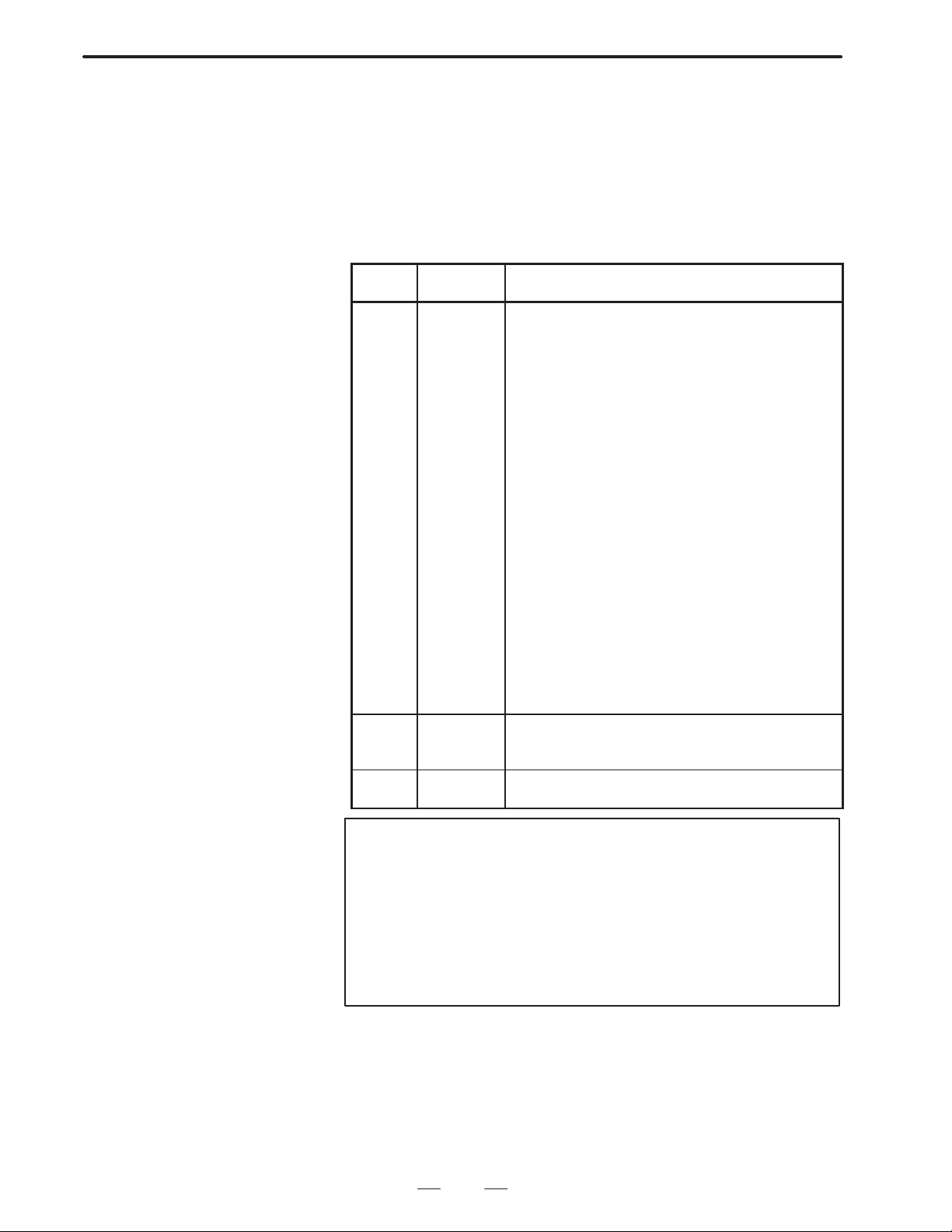
B–62073E–2/03
4.CONVERSATIONAL MACRO FUNCTION
If (above) is set, the machining parts total number is set to #500.
Further, the information of whether the window function in #501
has executed normally or not is set.
Caution
In the following cases, when the window function is executed, –1
(abnormal end) is set to #8996. When value inputted to #8997 is illegal.
When value inputted to #8998 exceeded 8 axes.
Reference system and information I.D. No. list
I.D. No.
(#8997)
10
12
13
14
15
16
17
18
19
30
31
32
33
34
35
36
200
201
202
300
301
1
2
3
4
5
6
7
8
9
11
Axis I.D. No.
(#8998)
–
–
–
–
–
–
–
–
–
–
1 to 6
1 to 6
1 to 6
1 to 6
1 to 6
1 to 6
1 to 6
1 to 6
1 to 6
–
–
–
–
–
–
–
–
–
–
–
–
Information contents
Alarm basic flag
OH alarm flag
SW alarm flag
PW alarm flag
OT alarm flag 1
OT alarm flag 2
OT alarm flag 3
OT alarm flag 4
I/O alarm flag
SV alarm flag
Axis type OT alarm flag 1
Axis type OT alarm flag 2
Axis type OT alarm flag 3
Axis type OH alarm flag
Axis type SV alarm flag 1
Axis type SV alarm flag 2
Axis type SV alarm flag 3
Axis type SV alarm flag 4
Axis type SV alarm flag 5
P/S alarm number (foreground)
P/S alarm number (background)
SR alarm number
External alarm number 1
External alarm number 2
External alarm number 3
External alarm number 4
Machining parts total number
Process time
Cutting time
Diagnose 1000
Diagnose 1001
Note
Axis I.D. No. is as described below.
Control 1st axis 1. . . . . .
Control 2nd axis 2. . . . .
Control 3rd axis 3. . . . . .
Control 4th axis 4. . . . . .
Control 5th axis 5. . . . . .
Control 6th axis 6. . . . . .
87
Page 91
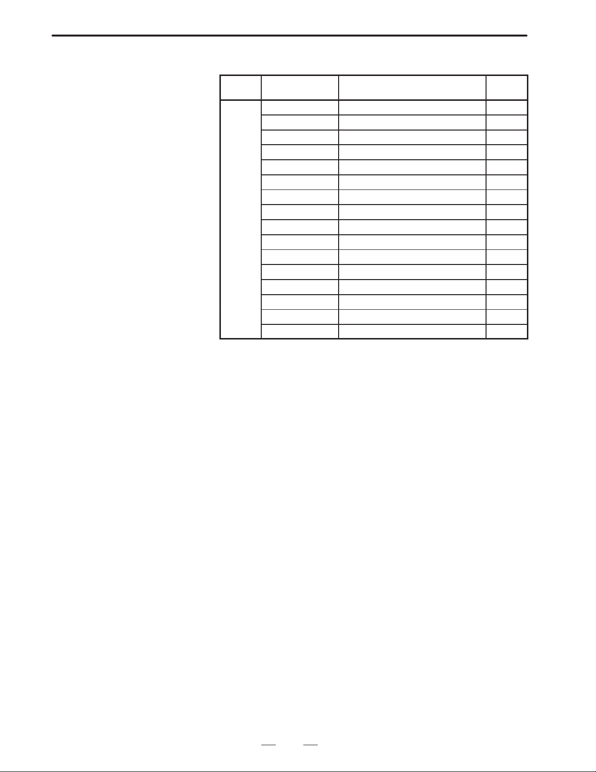
4. CONVERSATIONAL MACRO FUNCTION
1
Alarm basic flag
B–62073E–2/03
I.D No.
(#8997)
Bit name Information contents
BGPS (01H) Background P/S alarm
FGPS (02H) Foreground P/S alarm
OHALM (04H) OH alarm
– (08H) Undetermined
– (10H) Undetermined
SWON (20H) SW alarm
OTALM (40H) OT alarm
– (80H) Undetermined
EXTALM (100H) External alarm
– (200H) Undetermined
SRALM (400H) SR alarm
– (800H) Undetermined
SVALM (1000H) SV alarm
IOALM (2000H) I/O alarm
PWALM (4000H) PW alarm
– (8000H) Undetermined
External alarm:
When this bit is 1 it means that data has been set to external alarm
number 1, 2, 3, or 4.
SR alarm:
When this bit is 1 it means that data has been set to external alarm
number 1, 2, 3, or 4.
SV alarm:
When this bit is 1 it means that data has been set to SV alarm flag, or
axis type SV alarm flag 1, 2, 3, or 4.
IO alarm:
When this bit is 1 it means that data has been set to IO alarm flag.
PW alarm:
When this bit is 1 it means that data has been set to PW alarm flag.
Background P/S alarm:
When this bit is 1 it means that data has been set to P/S alarm number
(background).
Foreground P/S alarm:
When this bit is 1 it means that data has been set to P/S alarm number
(foreground).
OH alarm:
When this bit is 1 it means that data has been set to OH alarm flag
or axis type OH alarm flag.
SW alarm:
When this bit is 1 it means that data has been set to SW alarm flag.
OT alarm:
When this bit is 1 it means that data has been set to OT alarm flag 1,
2, 3 or 4, or axis type OT alarm flag 1, 2 or 3.
Error
code
88
Page 92

B–62073E–2/03
2
OH alarm flag
4.CONVERSATIONAL MACRO FUNCTION
I.D No.
(#8997)
OHLOK (01H) NC cabinet is over–heated OH001
– (02H) Undetermined
– (04H) Undetermined
– (08H) Undetermined
– (10H) Undetermined
– (20H) Undetermined
– (40H) Undetermined
– (80H) Undetermined
SW alarm flag
I.D No.
(#8997)
SWON (01H) State that parameter setting is pos-
– (02H) Undetermined
– (04H) Undetermined
3
– (08H) Undetermined
– (10H) Undetermined
– (20H) Undetermined
– (40H) Undetermined
– (80H) Undetermined
Bit name Information contents
Bit name Information contents
sible (parameter. data number 8000
PWE=1)
Error
code
Error
code
SW000
PW alarm flag
I.D No.
(#8997)
SWOFF (01H) Parameter for which power must be
PWMIS (02H) There is an error in the setting of a
– (04H) Undetermined
4
– (08H) Undetermined
– (10H) Undetermined
– (20H) Undetermined
– (40H) Undetermined
– (80H) Undetermined
Bit name Information contents
once interrupted has been set.
parameter related to straightness
compensation or inclination compensation.
Error
code
PW000
PW100
89
Page 93

4. CONVERSATIONAL MACRO FUNCTION
6
OT alarm flag 1
B–62073E–2/03
I.D No.
(#8997)
5
Bit name Information contents
– (01H) Undetermined
SPOH (02H) Spindle motor is overheated OT 101
SPVE (04H) Deviation between spindle motor
SPFU7 (08H) Spindle motor speed control unit
SPFU1 (10H) Spindle motor speed control unit
SPFUA (20H) Spindle motor speed control unit
SPEXA (40H) Spindle motor speed has exceeded
SPEXD (80H) Spindle motor speed has exceeded
OT alarm flag 2
I.D No.
(#8997)
Bit name Information contents
SP24V (01H) Spindle motor speed control unit
SPCND (02H) Power semi–coductor is overheated OT 109
SP15V (04H) Spindle motor speed control unit
SPHIV (08H) Spindle motor speed control unit
SPCUR (10H) Spindle motor speed control unit
SPCPU (20H) Spindle motor speed control unit
SPROM (40H) Spindle motor speed control unit
– (80H) Undetermined
Error
code
OT 012
commanded speed and actual
speed is excessive (15–20%)
OT 103
fuse F7 has been cut
OT 104
fuse F1, F2, or F3 has been cut
OT 105
fuse AF2 or AF3 has been cut
OT 106
maximum rating (analog detection)
OT 107
maximum rating (digital detection)
Error
code
OT 108
24V voltage is too high
OT 110
15V voltage is too low
OT 111
DC link section voltage has risen
excessively
OT 112
DC link section current has flowed
excessively
OT 113
CPU or peripheral circuit is abnormal
OT 114
ROM is abnormal
90
Page 94
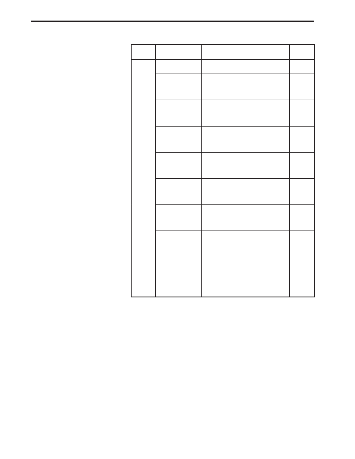
B–62073E–2/03
7
OT alarm flag 3
4.CONVERSATIONAL MACRO FUNCTION
I.D No.
(#8997)
Bit name Information contents
OTPCD (01H) Position coder disconnection has
been detected
OTADH (02H) External data input/output I/F signal
upper rank 4 bits are not defined
Address (major category) is not
specified
OTADL (04H) External data input/output I/F signal
lower rank 4 bits are not defined
Address (minor category) is not
specified
OTMOV (08H) More than 5 displays simulta-
neously requested for external;
operator message or external alarm
message display
OTNOM (10H) Because there is no specified mes-
sage number in cancel of external
operator message or external alarm
message, it cannot be cancelled.
OTOUT (20H) Output again requested during
external data output, Or, output
requested for address with no output data.
OTNUM (40H) Value specified outside range
0–999 for number of external operator message or external alarm
message
OTSRH (80H) There is no external data input pro-
gram number or number specified
by sequence number search. Or,
there is no program number specified by workpiece number search.
Tool data pot number and offset
amount input/output was requested,
but when power turned on tool
number input was not performed,
or, there is no tool data corresponding to inputted tool number.
Error
code
OT 116
OT 120
OT 121
OT 122
OT 123
OT 124
OT 125
OT 126
91
Page 95
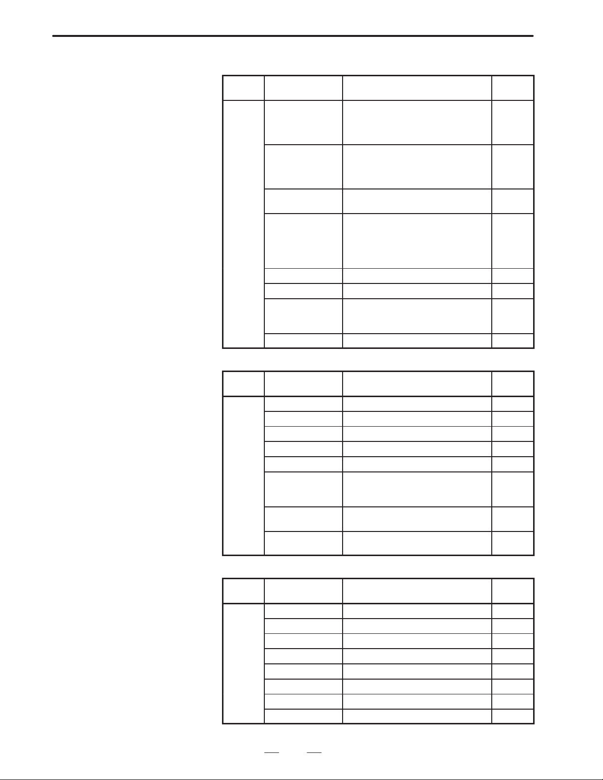
4. CONVERSATIONAL MACRO FUNCTION
10
OT alarm flag 4
B–62073E–2/03
I.D No.
(#8997)
OTHW (01H) Numerical value inputted by exter-
OTLL (02H) Numerical value inputted by exter-
OTREV (04H) Position coder CPU or peripheral
OTNOR (08H) Status that program number,
8
OTCVT (10H) A/D converter has failed. OT 150
– (20H) Undetermined
OTOTR (40H) There were input requests for pot
– (80H) Undetermined
I/O alarm flag
Bit name Information contents
nal data input data signal
EID32–EID47 has exceeded permissable range.
nal data input data signal
EID00–EID31 has exceeded allowable range.
circuit are abnormal.
sequence number search requests
cannot be received. (Because not
in memory mode or not in reset status)
number, offset number in the midst
of registering tool data by G10.
Error
code
OT 127
OT 128
OT 129
OT 130
OT 131
I.D No.
(#8997)
– (01H) Undetermined
– (02H) Undetermined
– (04H) Undetermined
– (08H) Undetermined
– (10H) Undetermined
9
100VR (20H) Attempted to perform writing or
10SUM (40H) NC memory 1 page unit checksome
10CHR (80H) Ilegal code has been read from NC
SV alarm flag
I.D No.
(#8997)
SVESP (01H) Emergency stop has been applied. SV 030
– (02H) Undetermined
– (04H) Undetermined
– (08H) Undetermined
– (10H) Undetermined
– (20H) Undetermined
– (40H) Undetermined
– (80H) Undetermined
Bit name Information contents
reading of data at address outside
file memory area.
is not correct.
memory .
Bit name Information contents
Error
code
IO 032
IO 303
IO 031
Error
code
92
Page 96

B–62073E–2/03
OT axis type alarm flag 1
4.CONVERSATIONAL MACRO FUNCTION
I.D No.
(#8997)
11
Bit name Information contents
OTSP1 (01H) Entered prohibited areas of stored
stroke limit 1 during shift in + direction.
OTSM1 (02H) Entered prohibited areas of stored
stroke limit 1 during shift in – direction.
OTSP2 (04H) Entered prohibited areas of stored
stroke limit 2 during shift in + direction. Entered prohibited areas of
check tailstock barrierduring shift in
+ direction.
OTSM2 (08H) Entered prohibited areas of stored
stroke limit 2 during shift in – direction. Entered prohibited areas of
check tailstock barrier during shift in
– direction.
OTSP3 (10H) Entered prohibited areas of stored
stroke limit 3 during shift in + direction.
OTSM3 (20H) Entered prohibited areas of stored
stroke limit 3 during shift in – direction.
OTHP (40H) Exceeded + side stroke limit switch. OT 007
OTHM (80M) Exceeded – side stroke limit switch. OT 008
Error
code
OT 001
OT 002
OT 003
OT 004
OT 005
OT 006
OT axis type alarm flag 2
I.D No.
(#8997)
12
Bit name Information contents
OTPSP (01H) Entered prohibited area in + direc-
OTPSM (02H) Entered prohibited area in – direc-
– (04H) Undetermined
– (08H) Undetermined
– (10H) Undetermined
– (20H) Undetermined
– (40H) Undetermined
– (80H) Undetermined
Error
code
OT 021
tion by preprocess stroke check.
OT 022
tion by preprocess stroke check.
93
Page 97

4. CONVERSATIONAL MACRO FUNCTION
14
OT axis type alarm flag 3
B–62073E–2/03
I.D No.
(#8997)
13
Bit name Information contents
OTAD2 (01H) A/D converter failed. OT 151
OTABS (02H) No correspondence between abso-
– (04H) Undetermined
– (08H) Undetermined
– (10H) Undetermined
– (20H) Undetermined
– (40H) Undetermined
– (80H) Undetermined
OH axis type alarm flag
I.D No.
(#8997)
Bit name Information contents
– (01H) Undetermined
OHMTR (02H) Servo motor is overheated. OH 000
– (04H) Undetermined
– (08H) Undetermined
– (10H) Undetermined
– (20H) Undetermined
– (40H) Undetermined
– (80H) Undetermined
Error
code
OT 032
lute pulse coder count value and
device coordinate
Error
code
SV axis type alarm flag 1
I.D No.
(#8997)
15
Bit name Information contents
SVTAC (01H) Taco generator disconnection alarm
SVEXC (02H) Servo motor excess load has been
SVBRK (04H) Speed control circuit breaker has
SVCUR (08H) Excess current has been detected
SVVOL (10H) Excess voltage has been detected
SVDIS (20H) Excess circuit current has been
SVLOW (40H) Low voltage has been detected by
– (80H) Undetermined
Error
code
SV 000
has been disconnected.
SV 001
detected (overload).
SV 002
been cut.
SV 003
by speed control circuit.
SV 004
by speed control circuit.
SV 005
detected by speed control circuit.
SV 006
speed control circuit.
94
Page 98

B–62073E–2/03
SV axis type alarm flag 2
4.CONVERSATIONAL MACRO FUNCTION
I.D No.
(#8997)
16
Bit name Information contents
SVSTP (01H) Position deviation amount during
SVMOV (02H) Position deviation amount during
SVDRF (04H) Drift amount is excessive. SV 010
SVLSI (08H) Position deviation amount has
SVMOT (10H) Speed of more than 512K pulse/
SVON (20H) Although position control ready sig-
SVOFF (40H) Although position control ready sig-
SVPDS (80H) Pulse coder disconnection was
SV axis type alarm flag 3
I.D No.
(#8997)
17
Bit name Information contents
SVLSI (01H) Abnormality was detected by posi-
SVFRE (02H) Abnormality was detected by
SVUNF (04H) Abnormality was detected in return
SVPHA (08H) Resolver or induction phase shift
SVRON (10H) Pulse coder 1 rotation signal was
SVRMS (20H) Pulse coder 1 rotation signal was
SVOVL (40H) Servo motor overload was
SVCMP (80H) Straightness compensation amount
Error
code
SV 008
stop exceeds parameter setting.
SV 009
process exceeds parameter setting.
SV 01 1
exceeded + –32767. Or, DA converter speed command value is outside the range –8192 – +8192
SV 012
sec. has been commanded.
SV 013
nal (PRDY) was on, speed control
ready signal (VRDY) became off.
SV 014
nal (PRDY) was off, speed control
ready signal (VRDY) became on.
SV 015
detected.
Error
code
SV 017
tion control LSI.
SV 018
resolver or induction feedback frequency check.
SV 019
pulse from pulsecoder.
SV 020
amount cannot be correctly
requested.
SV 021
set on at abnormal location.
SV 022
set on at abnormal location.
SV 023
detected.
SV 100
exceeded 32767.
95
Page 99

4. CONVERSATIONAL MACRO FUNCTION
18
19
SV axis type alarm flag 4
B–62073E–2/03
I.D No.
(#8997)
Bit name Information contents
– (01H) Undetermined
SVABS (02H) Absolute pulse coder failure or
– (04H) Undetermined
– (08H) Undetermined
– (10H) Undetermined
– (20H) Undetermined
– (40H) Undetermined
– (80H) Undetermined
SV axis type alarm flag 5
I.D No.
(#8997)
Bit name Information contents
SVCVO (01H) When servo control is on, speed
SVARG (02H) Servo axis arrangement parameter
– (04H) Undetermined
– (08H) Undetermined
– (10H) Undetermined
– (20H) Undetermined
– (40H) Undetermined
– (80H) Undetermined
Error
code
SV 101
device position for greatly moving
the device when turning on power
was not correctly requested.
Error
code
SV 025
control ready signal is on although it
should be off.
SV 026
is not correctly set.
4.5.19
Reading Relative
Coordinates by
Conversational Macro,
and Preset
Alarm number
I.D No.
(#8997)
30 Foreground P/S alarm number
31 Background P/S alarm number
32 SR alarm number
33 External alarm number
34 External alarm number
35 External alarm number
36 External alarm number
Information contents
(1) Reading relative coordinates
Reading the relative coordinate value can be performed by
conversational macro.
Set the axis number to perform relative coordinate value reading to
#8998, and the relative coordinate value can be read by #8999.
96
Page 100

B–62073E–2/03
4.CONVERSATIONAL MACRO FUNCTION
#8996 : Complete code
#8997 : Information I.D.
#8998 : Axis number
#8999 : Relative coordinate value
Caution
Macro
Variable
#8997
#8998 Axis number (1 to 8)
#8999 Relative cordinate value
#8996
Information ID
500: Reading relative coordinate
Complete code
0: Normal end
–1: Abnormal end
Contents
Example:
Relative coordinate value of 1st axis is read as –123456 to #500 if
#8997=500 ;
#8998=1; (Incorporates contents of 1st axis)
#500=#8999;
is set when –123.456
1)
The value which will be read by #8999 is <Vacant> when a value outside
1–8 is specified to #8998.
2) For #8998, 0 is set when turning on the power.
(2) Preset of relative coordinate value
The relative coordinate value can be freely preset by G360 Aa Qq.
The axis number is set in address A.
A1 to 8
Set the relative coordinate you desire to preset to address Q.
Q–999999999 to 999999999
The relative coordinate value can be preset by executing this control
code.
Example:
When you desire to preset the relative coordinate value of 1st axis to
–123.45
G360 A1 Q–123450 ;
Caution
4.5.20
Address Function
1) G360 command is ignored when a value other than 1 to 8 is specified
to address A, or when A is not specified.
2) The units of address Q are the minimum setting units of the specified
axis.
The address function is that which returns the PMC address or NC
parameter contents as a functional value. However, the address function
cannot be described to the left side of the calculation because it cannot be
written.
97
 Loading...