

Page 1
Gibbs and Associates
323 Science Drive
Moorpark, CA 93021
(805) 523-0004
March 1999
GEOMETRY CREATION
USER MANUAL
Page 2

PROPRIETARY NOTICE
This document contains propriety information of Gibbs and Associates and is to be used only
pursuant to and in conjunction with the license granted to you with respect to the accompanying Gibbs
and Associates licensed software. Except as expressly permitted in the license, no part of this document
may be reproduced, transmitted, transcribed, stored in a retrieval system, or translated into any language
or computer language, in any form or by any means, electronic, magnetic, optical, chemical, manual or
otherwise, without the prior written permission from a duly authorized representative of Gibbs and
Associates.
It is strongly advised that you carefully review the license in order that you understand your
rights and obligations related to the licensed software and the accompanying user documentation.
Use of the computer software and the user documentation has been provided pursuant to a
Gibbs and Associates license agreement.
© Copyright 1996 Gibbs and Associates, Inc.
All Rights Reserved
Acknowledgements:
Written by Shannon McConville.
Thanks to Tim Alvord, Sean Canterbury, Gary Esser, Bill Gibbs, Charles Haden, Tom Hubina, Pete
Jackson, Kristin Kelley, Michael Kelley, Israel Klain, James Moore, Jeff Myers and Robb Weinstein for
their input and assistance.
Trademarks:
Windows NT, Windows 95 and Windows 98 are trademarks of Microsoft Corporation
Macintosh is a trademark of Apple Computer, Inc.
Printed in the United States of America
◆
Geometry Creation User Manual GFK-1 7 0 3
Page 3

Table of Contents
CHAPTER 1
:
INTRODUCTION III
How to Learn the System . . . . . . . . . . . . . . . . . . . . . . . . . iii
Balloons and Prompting . . . . . . . . . . . . . . . . . . . . . . . . . iii
Operating Systems Glossary . . . . . . . . . . . . . . . . . . . . . . . . iii
System Overview . . . . . . . . . . . . . . . . . . . . . . . . . . . . iii
CHAPTER 2
:
INTERFACE 1
Cursors . . . . . . . . . . . . . . . . . . . . . . . . . . . . . . . . 1
Actions . . . . . . . . . . . . . . . . . . . . . . . . . . . . . . . . 2
Objects . . . . . . . . . . . . . . . . . . . . . . . . . . . . . . . . 2
Shortcuts . . . . . . . . . . . . . . . . . . . . . . . . . . . . . . . . 9
Selection . . . . . . . . . . . . . . . . . . . . . . . . . . . . . . . . 10
Colors . . . . . . . . . . . . . . . . . . . . . . . . . . . . . . . . . 11
Clipboard . . . . . . . . . . . . . . . . . . . . . . . . . . . . . . . 11
CHAPTER 3
:
PART SET-UP 13
Document Control Dialog . . . . . . . . . . . . . . . . . . . . . . . . . 13
CHAPTER 4
:
GEOMETRY CREATION 16
Geometry Overview . . . . . . . . . . . . . . . . . . . . . . . . . . . 16
Geometry Creation Palette . . . . . . . . . . . . . . . . . . . . . . . . . 17
Geometry Expert. . . . . . . . . . . . . . . . . . . . . . . . . . . . . 18
Free Form CAD . . . . . . . . . . . . . . . . . . . . . . . . . . . . . 26
Text Creation . . . . . . . . . . . . . . . . . . . . . . . . . . . . . . 31
Curve Creation . . . . . . . . . . . . . . . . . . . . . . . . . . . . . 35
Workgroups. . . . . . . . . . . . . . . . . . . . . . . . . . . . . . . 37
Shapes and Connectors . . . . . . . . . . . . . . . . . . . . . . . . . . 39
Edit Menu . . . . . . . . . . . . . . . . . . . . . . . . . . . . . . . 41
Modify Menu . . . . . . . . . . . . . . . . . . . . . . . . . . . . . . 43
File Import . . . . . . . . . . . . . . . . . . . . . . . . . . . . . . . 46
File Export . . . . . . . . . . . . . . . . . . . . . . . . . . . . . . . 52
Workgroup Summary . . . . . . . . . . . . . . . . . . . . . . . . . . . 56
Printing the Part Geometry . . . . . . . . . . . . . . . . . . . . . . . . . 57
GFK-1703 Table of Contents
◆
i
Page 4

◆
Geometry Creation User Manual GFK-1 7 0 3
ii
CHAPTER 5
:
GEOMETRY EXPERT EXERCISES 58
Exercise #1: Shaft . . . . . . . . . . . . . . . . . . . . . . . . . . . . 58
Exercise #2: Chassis . . . . . . . . . . . . . . . . . . . . . . . . . . . 73
Exercise #3: Shuttle . . . . . . . . . . . . . . . . . . . . . . . . . . . 98
Exercise #4: Lathe Tutorial . . . . . . . . . . . . . . . . . . . . . . . . 106
Exercise #5: Doodle . . . . . . . . . . . . . . . . . . . . . . . . . . . 115
Exercise #6: Bell Crank . . . . . . . . . . . . . . . . . . . . . . . . . . 122
CHAPTER 6
:
FREE FORM CAD EXERCISES 135
Exercise #1: Shapes and Connectors . . . . . . . . . . . . . . . . . . . . . 135
Exercise #2: Mill Tutorial . . . . . . . . . . . . . . . . . . . . . . . . . 150
Exercise #3: Lathe Tutorial . . . . . . . . . . . . . . . . . . . . . . . . . 181
Exercise #4: Shuttle . . . . . . . . . . . . . . . . . . . . . . . . . . . . 219
Exercise #5: Text Creation . . . . . . . . . . . . . . . . . . . . . . . . . 232
Exercise #6: Overlapping Features . . . . . . . . . . . . . . . . . . . . . . 237
CHAPTER 7
:
COMBINATION EXERCISES 245
Exercise #1: Loading Shapes ..................................................256
Exercise #2: Mill Tutorial ....................................................257
Exercise #3: Gear Housing ....................................................272
APPENDIX 1
:
OPERATING SYSTEMS 277
Launching the System........................................................277
Operating Systems Glossary ...................................................277
File Compatibility ...........................................................278
Standard Extensions .........................................................278
Post Processor Formats .......................................................279
APPENDIX 2
:
PART PRINTS 280
Part Print #1: Shaft ..........................................................280
Part Print #2: Chassis ........................................................281
Part Print #3: Shuttle.........................................................282
Part Print #4: Lathe Tutorial ...................................................283
Part Print #5: Doodle ........................................................284
Part Print #6: Mill Tutorial ....................................................285
Part Print #7: Gear Housing ...................................................286
Part Print #8: Bell Crank......................................................287
INDEX 288
Page 5
GFK-1703 Introduction
◆
iii
CHAPTER 1
:
Introduction
HOW TO LEARN THE SYSTEM
Congratulations on purchasing the most productive programming system available! It is rec-
ommended that the Geometry Creation Manual be reviewed before moving on to either the Mill or
Lathe Module Manuals. The best way to learn the system is to read the reference information and
complete the geometry exercises. Then complete the tutorials provided in the module specific manuals. For simple explanations of on-screen items and their purpose, use Balloons and Prompting pro-
vided in the Help menu.
BALLOONS AND PROMPTING
Balloons and Prompting are built-in documentation and training information, also known as
CAT (Computer Aided Training). They can be turned on from selections under the Help menu.
Balloons provide reference information about any object that the cursor is placed over. Prompting
extends certain palettes in the system to provide useful suggestions about how to proceed. They are
very useful.
OPERATING SYSTEMS GLOSSARY
The Windows NT®, Windows 95/98® and MacOS® operating systems use different terminology for certain common items. A short list has been provided to help eliminate possible confusion.
Refer to the Operating Systems Appendix for additional information on the differences between the
Windows NT, Windows 95/98 and Macintosh operating systems.
EQUIVALENT TERMS
file = document
program = application
directory = folder
backspace key (not delete or del) = delete key (not del)
Operating system symbol : This symbol appears throughout the manual to indicate when
there are variations in specific system functions depending on the operating system.
O
S
Page 6
◆
Geometry Creation User Manual GFK-1 7 0 3
iv
SYSTEM OVERVIEW
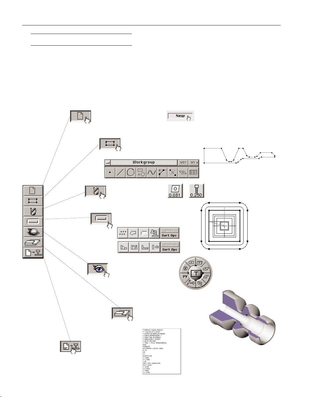
This system is designed to be extremely flexible, to allow the user the freedom to create parts
in any way that comes naturally. The "modeless" interface allows the user to have geometry creation, tools, machining capabilities and post processing functions available at all times. However,
there are certain basic elements required to create a part. There must be geometry, a tool, and a
toolpath (an operation) created before post processing. The Top Level palette is organized in a logical manner for building a part. A part does not have to be created in this order, it only serves as a
guideline.
Create a new file.
Create part geometry.
Create a tool.
Create a toolpath.
Cut Part Render
Post Process.
Change the view.
Page 7
GFK-1703 Interface
◆
1
CHAPTER 2
:
Interface
This system uses a Graphic User Interface (GUI). This simply means that pictures or symbols
are used in place of text whenever possible. This section of the manual describes the different interface objects and their uses.
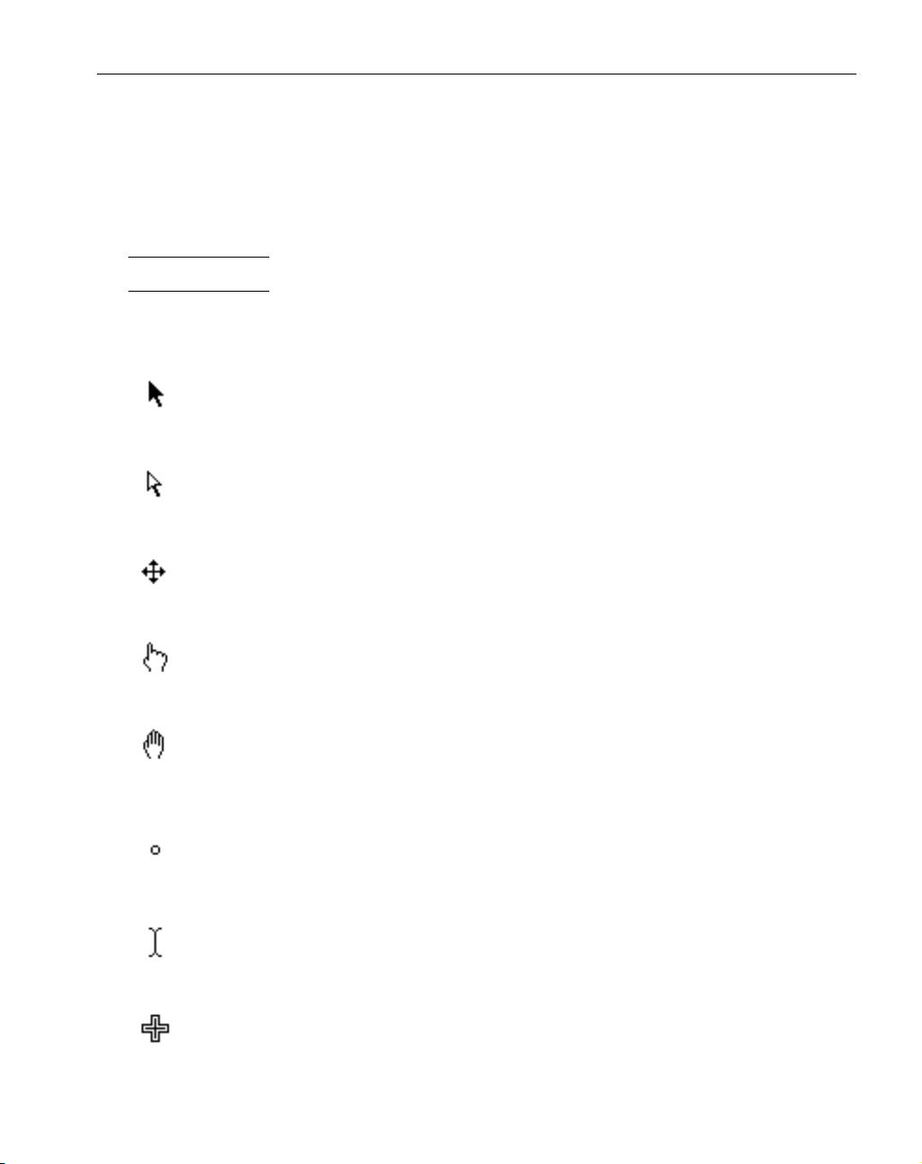
CURSORS
The cursor is the object moved with the mouse. Its appearance changes depending on its location. The appearance of the cursor dictates its usage.
Black Pointer : This cursor is used to select objects and geometry by clicking on them. Zoom
by dragging a rectangle around an area on the screen.
White Pointer : This cursor functions the same as the black pointer, except it is in multiple
selection mode. The white pointer appears when the Shift key is held down or when a geometry sub-palette is open. It allows more than one item to be selected at a time.
Mover Tool : This indicates that the cursor is placed on the edge of a palette or in a dialog’s
title bar. Move the palette or dialog by holding the mouse button down and dragging it to a
different location.
Pointing Finger : This indicates that the cursor is over a button. Push the button by clicking on
it.
Hand : This indicates that the cursor is over a draggable object such as a tile. Move the object
by clicking on it once and dragging it to the desired location. This cursor is also used to roll
the trackball.
Spot : The cursor changes to this while rolling the trackball.
I Beam : This indicates that the cursor is in a location where text input is accepted. It is a
flashing cursor.
Area Select : The cursor changes to this while doing a mouse drag or zooming in on an area.
Page 8
◆
Geometry Creation User Manual GFK-1 7 0 3
2
ACTIONS
There are a number of actions used throughout the system.
• Moving the cursor : The cursor is moved and positioned with the mouse.
• Click : A quick tap on any mouse button.
• Double-click : Two quick taps on the mouse button.
• Type : Using the keyboard.
• Drag : Position cursor, hold mouse button down, reposition cursor, release mouse button.
• Shift-click : Hold shift key down while clicking the mouse.
• Shift-double-click, Ctrl-click, Ctrl-double-click, etc. : Hold down stated key and
click (or double-click).
OBJECTS
There are several interface objects used throughout the system. The Tile Lists and Machining
Markers will be described in the machining manuals for the Mill and Lathe modules.
• Drawing Window
• Palettes
• Dialogs
• Tile Lists
• Menus
• Machining Markers
• Balloons/Prompts
• Wastecan
g
Menu Bar
Drawing
Window
Tile List
Balloon
Palette
Prompt
Dialo
Wastecan
Page 9
GFK-1703 Interface
◆
3
DRAWING WINDOW
The drawing window is the full size of the screen. All drawing of geometry, toolpaths, and
rendered images appear in the drawing window. It is not moveable. All other interface objects
appear in front of the drawing window.
PALETTES
A palette is a collection of functions grouped together in a logical manner for the user. Some
palettes are moveable, others are not.
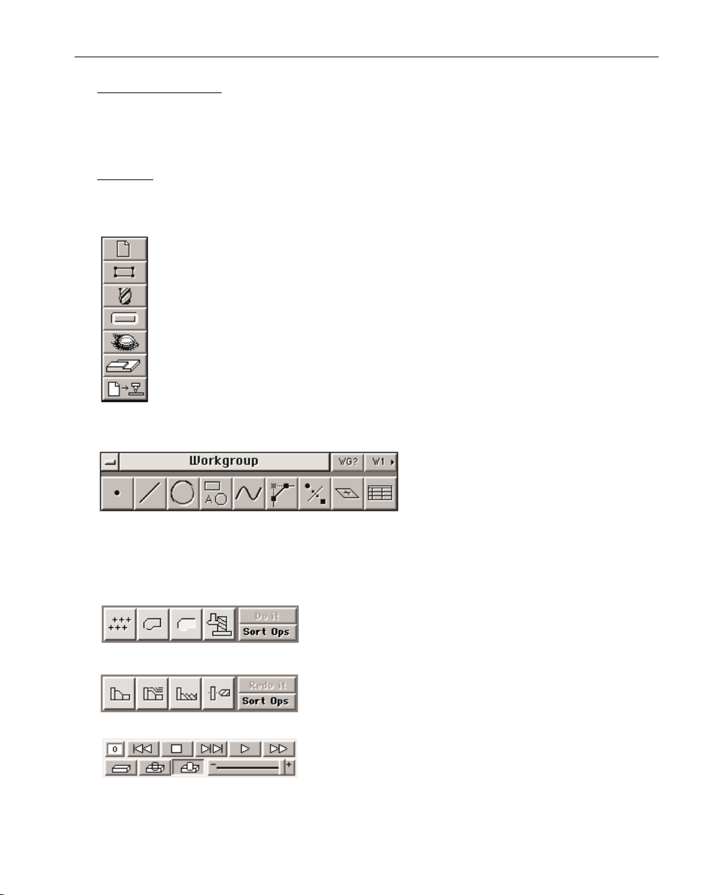
Top Level Palette: This palette is made up of buttons. These buttons can be either “on”
(depressed) or “off” (raised). Clicking once on a button turns it on and accesses the appropriate dialog or palette. Another click will turn the button off and put any dialogs or
palettes away. The top level palette cannot be moved.
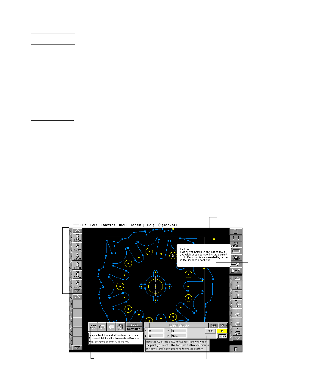
Geometry Creation Palette: This palette is also
made up of a group of buttons. However,
when one of the buttons is clicked on, it does
not stay depressed. Instead, it brings up a
sub-palette or the Geometry Expert
Spreadsheet. The Geometry Creation Palette can be moved to any location on the screen. Move the
palette by placing the cursor in the title bar of the palette. When the cursor changes to the mover
tool, hold the mouse button down and move the palette. This action is called “dragging the edge”.
Mill
Machining Palette: This palette is made up of Function Tiles and
buttons. The four Function Tiles are moveable objects that can
be dragged to the Process List to create operations. The
Lathe Machining Palette can be moved to any location on the screen.
Render palette: This palette provides control over the cut part
rendering process. It allows the user to control rendering
speed, the operations that will be rendered, and the way the
tool will be displayed. This is also a moveable palette.
Page 10
◆
Geometry Creation User Manual GFK-1 7 0 3
4
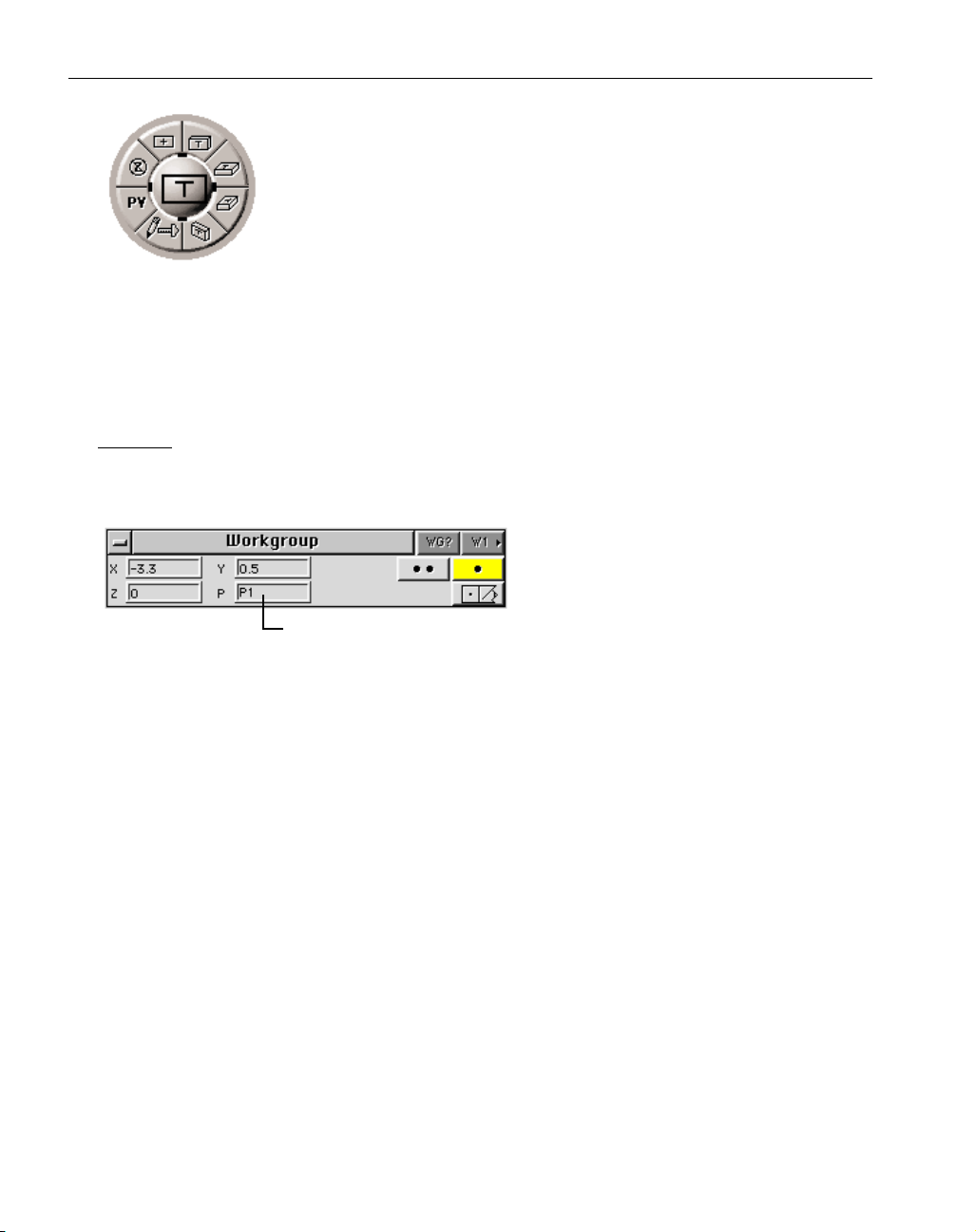
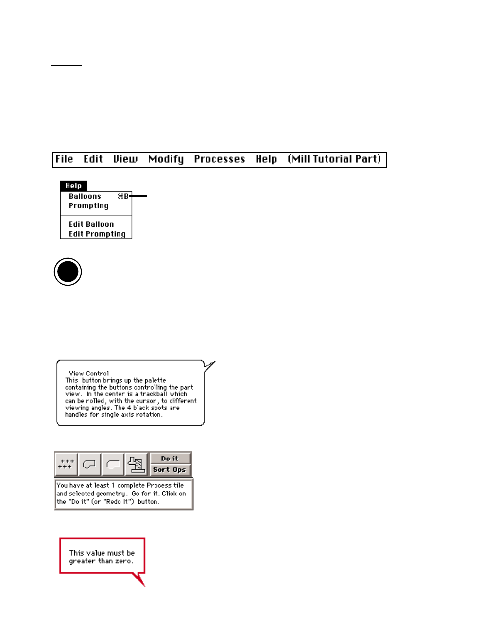
View Control Palette (Trackball) : The View Control Palette allows the user to easily change the current view of the part. The buttons around the outside provide
standard view changes, redraws and unzooms. The center ball operates like a
trackball and rolls to allow the part to be viewed from any orientation. When
the cursor is placed over the ball, it changes into a hand, which indicates that
the ball can be rolled. Holding the mouse button down and moving the mouse
will roll the trackball. The black outlined box on the ball represents the orien-
tation of the part. The "T" identifies the top surface of the part. The dimensions of the box do not change with the actual part size. Once the desired view is obtained, and the
mouse button is released, the part is redrawn in the new view. The ball has four small solid black
rectangles around it, inside the ring of buttons (located at 12:00, 3:00, 6:00, 9:00). These are called
ball "handles". Drag these handles for a single axis view change. The trackball is a moveable
palette, drag its edge to move it.
DIALOGS
Dialogs are used when information is needed from the user. This information is conveyed
through text boxes, radio buttons, yes/no buttons, and pop-up menus.
Text boxes: Items that require keyboard input
have a box next to them. If you click once in
a text box, a flashing text cursor will appear
where you clicked. Any typed input will
begin at the flashing text cursor. To move
the text cursor, simply click the desired location. Double clicking in a text box will select (highlight) everything in the text box. Anything
typed at this point will completely replace the current contents of the box. To select only portions of
the contents of the text box, click before or after the text to be edited, hold the mouse button down
and drag.
Moving from one text box to another can be accomplished by clicking or double clicking in
the desired box, or hitting the Tab key. Hitting the Tab key moves the cursor from box to box, and
highlights the entire contents of each box.
The contents of all text boxes can be cut, copied and pasted to and from the Clipboard by
choosing items from the Edit Menu.
Math Input in a Text box: All number input boxes will accept the four standard math function symbols
(+ - x / ), as well as a number of special functions, (both * and x are used for multiplication).
Hitting the equal key or tab key on the keyboard will display the final value. Special math functions
include:
r = squareroot
s= sine
c= cosine
t= tangent
a= arctangent
m= convert from inch to millimeter (x 25.4)
i= convert from millimeter to inch (/ 25.4)
Text Box
Page 11
GFK-1703 Interface
◆
5
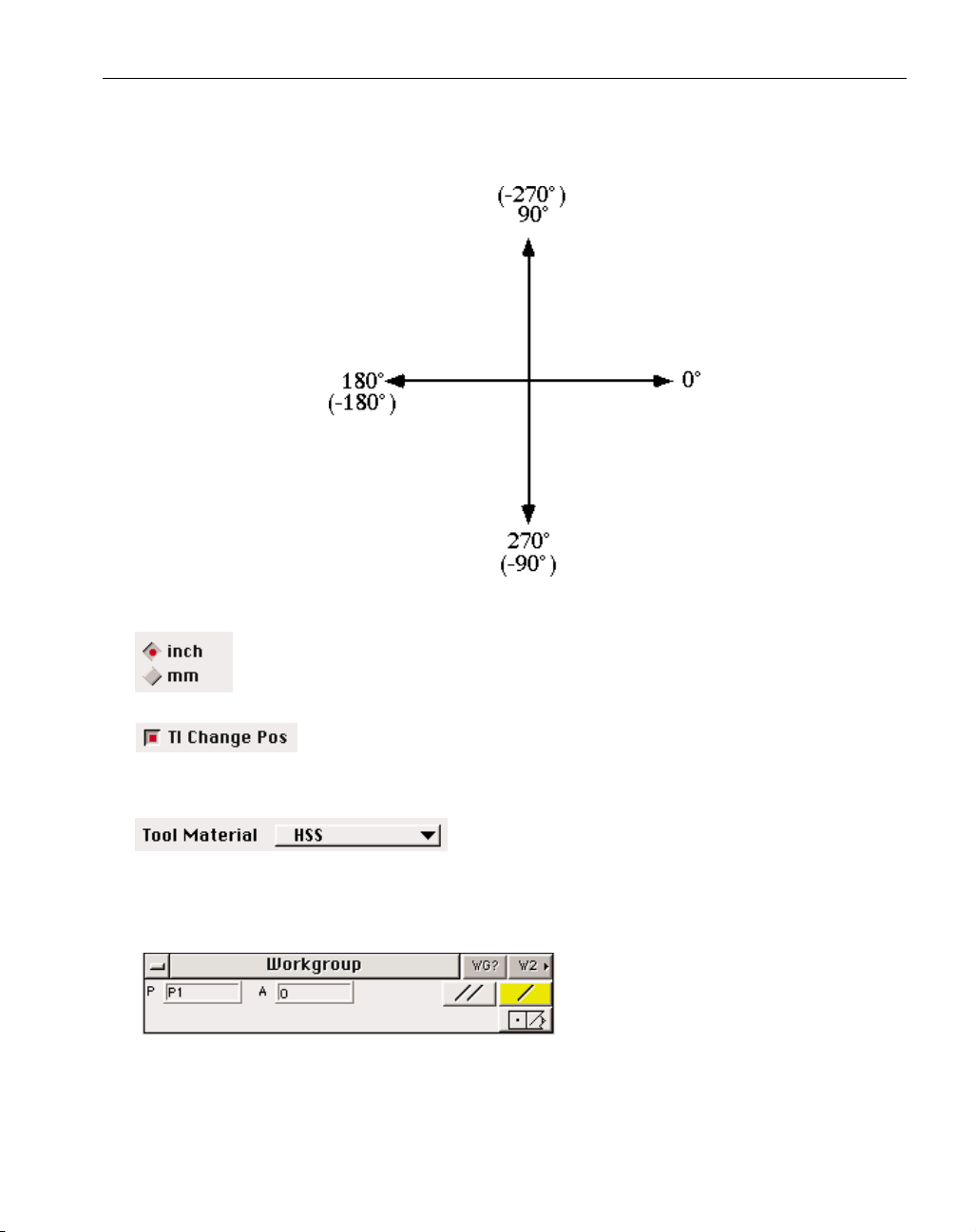
Angle values follow the standard Cartesian coordinate system, as shown below. Negative val-
ues are acceptable as input.
Radio buttons: Radio buttons come in groups. When one of the buttons in the group
is depressed (turned "on"), the other buttons in the group are "off." The button that
is depressed displays a small red dot or "light" to indicate that it is "on".
Yes/No buttons:Yes/No buttons come one per option. Depress the button for
yes, pop it up for no. The button that is depressed displays a small red dot or
"light" to indicate that it is "on".
Pop-Up menus : Pop-up menus provide multiple choices. A
pop-up menu looks like a button, but has an arrow indicating that there are more choices available. The menu is accessed by depressing it and dragging the
cursor down to scroll through the list. When the desired item is highlighted, release the mouse button to select it.
Geometry Dialog : Geometry Dialogs are
used for input of specific geometry information when creating shapes. All Geometry
Dialogs contains buttons that access the
Workgroup Information and Selection
Dialogs.
Page 12
◆
Geometry Creation User Manual GFK-1 7 0 3
6
Moveable dialogs : Some dialogs
may be moved around on the
screen. The area at the top of the
dialog is called the title bar. The
title bar shows the name of the
dialog. Drag the title bar to move
the dialog. The small box in the
upper left corner of the window is
the close box. Clicking in this box
puts the dialog away. Doubleclicking on the title bar will hide
the dialog and leave only the title
bar. An additional double-click
will restore the dialog. This is
useful for conserving screen
space. Most of the dialogs in the
system can be shrunk to the title
bar in this manner.
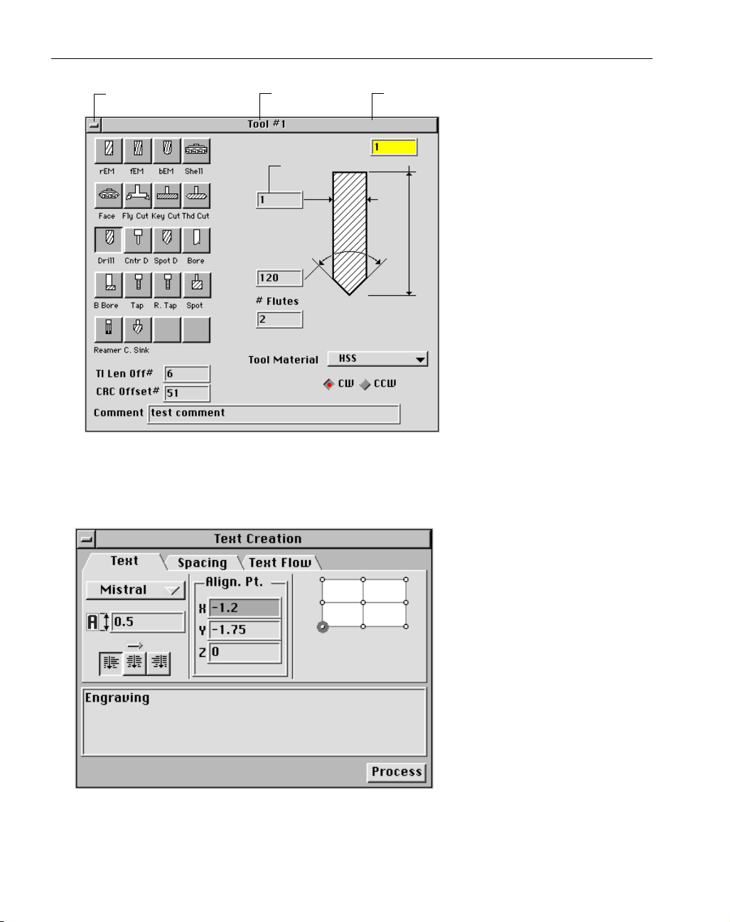
Text Creation Dialog : The Text
Creation Dialog contains “tabs” that
allow the user to access the Text,
Spacing, and Text Flow windows
contained within the dialog. Click
on the tabs to access the desired
window. The bottom portion of the
dialog where text can be entered
and the Process button remain available regardless of what window is
currently being viewed.
Close box
Dialog Name Title Bar
Page 13
GFK-1703 Interface
◆
7
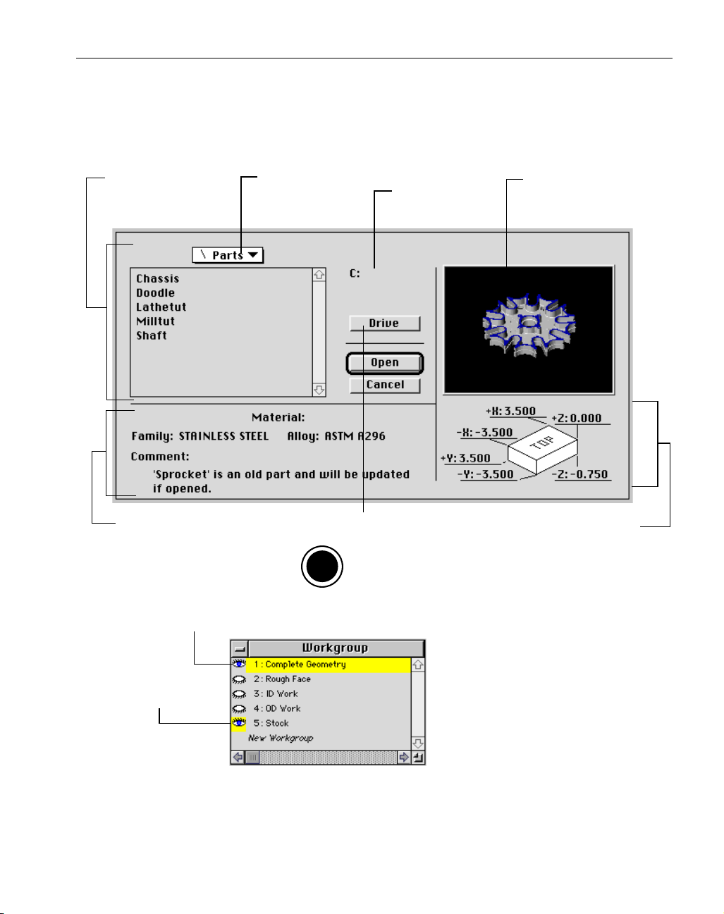
Open Dialog : The Open Dialog is used to locate, view, and open files. It comes up when Open is
selected from the File menu, or the Open button is depressed in the Document Control Dialog. The
part dimensions shown in the dialog below are for a mill part. If a lathe part is being opened, the
part dimension picture will change accordingly.
Workgroup Selection Dialog : The
Workgroup Selection Dialog is used to
create new workgroups, switch between
workgroups and select workgroups to
be viewed as background workgroups.
The current workgroup is highlighted in
yellow. Double-clicking on an eyeball
will change the viewing of a back-
ground workgroup. Geometry contained
in background workgroups will be drawn in gray, and cannot be edited or selected as a cut shape to
create machining operations. To select multiple workgroups to be viewed as background workgroups, use the Show Selected WG item in the View Menu. Holding down the Shift key will allow
more than one eye icon to be selected at a time to be viewed.
Current Directory/Folder:
displays a list of all
available files in the
current directory
Material Information
and Part Comment
Pop-up menu to
access a higher level
directory; displays
current directory
Button used to access the available drives
and disks contained on the system.
O
S
Name of the
current disk
On DOS, Windows NT an Windows 95
systems, it is the Drive button as
shown above. On Macintosh systems,
it is the Desktop button.
Part Preview:
displays the last
rendered image
of the part
Part Dimensions
Current Workgroup
Background Workgroup
Page 14
◆
Geometry Creation User Manual GFK-1 7 0 3
8
MENUS
Menu Bar: The menu bar, shown below, is located at the top of the screen. It is available to the user
at all times. To access the menu bar, position the cursor over the menu bar title, hold the mouse button down, drag the cursor down until the desired item is highlighted, and release the mouse button.
If a menu item is grayed out it cannot be selected. Selecting geometry or some other appropriate
item on the screen may change the menu item so that it becomes black and can be selected. Some
menu items are grayed out because certain modules of the software are not installed with the system.
Keyboard Shortcuts : Many menu items can also be accessed
by the keyboard. The symbol and letter next to the menu
item indicate that depressing a modifier key along with the
letter will access that menu item.
The modifier keys used to perform certain shortcuts in the system vary depending on the
operating system. The Shortcuts information card or the Shortcuts Appendix provide complete listings of the specific modifier keys used on each operating system.
BALLOONS/PROMPTS
Balloons and prompts provide on-line reference information about the objects and functions in
the system.
Balloons: Balloons are turned on in the Help menu. A bal-
loon containing reference information will appear when
the cursor is placed over an object on the screen.
Prompting: Prompting is also turned on in the Help menu.
Prompting extends the geometry and machining palettes to
include useful suggestions on how to use the software.
Error Balloons: Error balloons alert the user whenever an invalid value has
been entered. They are outlined in red and disappear when a valid entry is
made.
Keyboard Shortcut
O
S
Page 15
GFK-1703 Interface
◆
9
SHORTCUTS
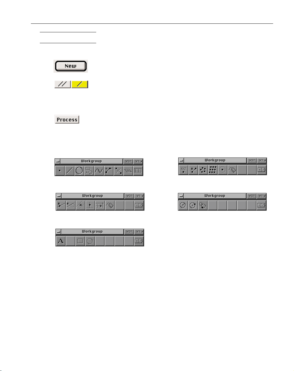
Button Shortcuts : In some cases, buttons may be depressed by actions other than clicking on them.
When a button has a black outline around it, it can be depressed by hitting the
enter or return key.
Geometry Dialogs give the user a choice of single or multiple feature cre-
ation. To create only one feature (a line, for example), click on the single line
button. To create more than one line, click on the multiple line button. One of the buttons will
always be highlighted. The highlighted button can be depressed by clicking on it, hitting the
space bar, the enter key, or the return key.
The Process button is found in some dialogs, primarily those found in the Modify
menu. It can be depressed by clicking on it, or by hitting the enter or return keys.
Palette Shortcuts: There are some keyboard shortcuts for functions other than menu choices in the
system. Simply hit the appropriate number to activate the button.
Geometry Creation Palette Point Sub-Palette
Line Sub-Palette Circle Sub-Palette
Auto-shape Sub-Palette
The system contains many other shortcuts that are described on platform specific Shortcuts
information cards and in the Shortcuts Appendix.
1234 5 7 986
12345 6
12345 6
123
123
Page 16

◆
Geometry Creation User Manual GFK-1 7 0 3
10
SELECTION
Three classes of objects may be selected in the system: text, geometry features and tiles. Text
and geometry can be cut, copied, and pasted to and from the clipboard within the same file by using
items in the Edit Menu. Selection techniques are described below.
TEXT SELECTION
To select text:
•
Click and drag the cursor over some text.
The text will become selected.
•
Double-click in a text box.
All text in the box will become selected.
•
Hit the tab key to move from text box to another.
All text in the box will become selected.
GEOMETRY SELECTION
To select a single geometry feature:
•
Click on a feature.
The feature will become selected. If any other features were selected, they will
become deselected.
To select multiple geometry features:
•
Shift-click on a feature.
If the feature was unselected, it will become selected and added to any other currently
selected features. If the feature was selected, it will become deselected and removed from
the currently selected group.
Holding down the shift key changes the cursor to multiple selection mode which
allows more than one geometry feature to be selected at a time.
To select an entire connected shape:
•
Double-click on a feature of the shape.
All connected features will become selected.
To select certain types of geometry:
•
Use the Select items found under the Edit menu.
All geometry that matches the selected type will become selected and added to the
currently selected group.
TILE SELECTION
To select a single tile:
•
Click on a tile.
The tile will become selected. If any other tiles were selected, they will become deselected.
To select multiple tiles:
•
Shift-click on a tile.
Page 17

GFK-1703 Interface
◆
11
If the tile was unselected, it will become selected and added to any other currently
selected tiles. If the tile was selected, it will become deselected and removed from the currently selected group.
Holding down the shift key changes the cursor to multiple selection mode which
allows more than one tile to be selected at a time.
For additional selection shortcuts, refer to the Shortcuts information card or the Shortcuts
Appendix.
COLORS
The system uses colors to graphically display different items drawn on the screen. The color
scheme for geometry, toolpaths and rendering is listed below.
GEOMETRY
Yellow Unconnected Geometry
Dashed Yellow Unconnected Rapid Geometry
Light Blue Connected Geometry
Dashed Light Blue Connected Rapid Geometry
Gray Geometry viewed as a background workgroup
TOOLPATHS
Dark Blue Cut Shape; selected area of a shape to be machined
Solid Orange Feed Move in a Toolpath
Dashed Orange Rapid Move in a Toolpath
Dashed Gray Rapid Move used for positioning moves and tool changes
Solid Gray Approach Feed Move
RENDERING
Blue Stock
Yellow Rendering of selected operations, and/or selected tools
Gray Rendering of unselected operations and/or unselected tools
Red Tool Interference
CLIPBOARD
The clipboard is used as a temporary storage place for geometry and text. Using the Cut option
from the Edit menu will delete whatever items are selected and replace the contents of the clipboard
with them. Using Copy will leave the selected items in their current location and replace the contents of the clipboard with a duplicate of them. Choosing Paste can do two things. If something is
selected it will replace that selection with the contents of the clipboard. If nothing is selected the
contents of the clipboard will be pasted in either the drawing window or in an active text box
depending on whether the clipboard contains text or geometry. The clipboard can only hold one
selection at a time. This means that it can hold either text or geometry, but not both. If text is copied
into a clipboard holding geometry, the geometry in the clipboard will be lost. The contents of the
clipboard will also be lost, when a file is closed, the software is quit out of, or the computer is shut-
Page 18

◆
Geometry Creation User Manual GFK-1 7 0 3
12
down.
It is possible to cut and paste geometry within a part file between different workgroups.
However, geometry cannot be cut, copied or pasted between different part files because the contents
of the clipboard are deleted when the part file is closed.
Page 19
GFK-1703 Part Set-Up
◆
13
CHAPTER 3
:
Part Set-Up
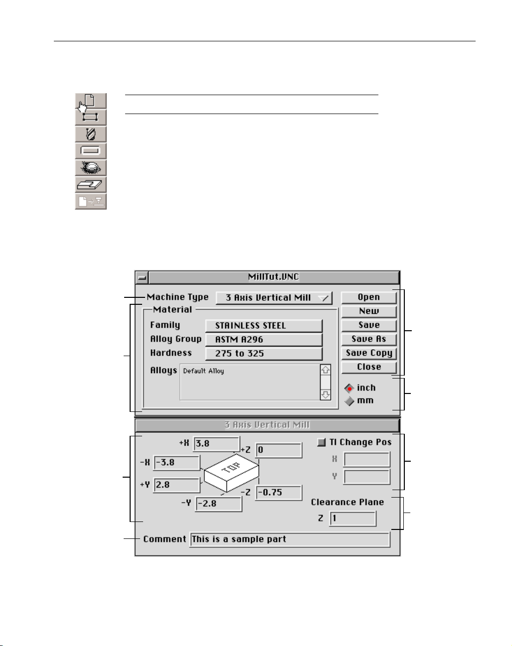
DOCUMENT CONTROL DIALOG
Clicking on the Document Control Button will bring up the Document Control
Dialog. This dialog is actually a combination of two linked dialogs. The top dialog
contains general information about the file and gives the user control over where it is
stored on the computer. The top dialog is the same for both the Mill and Lathe modules. All of the items in the top dialog, except for Material information, will be
described in this section. The Material database will be outlined in the machining
manuals for the Mill and Lathe modules.
The bottom dialog changes according to the Machine Type selected in the top
dialog. The bottom dialog contains information on stock size, clearance positioning
and tool change position. Only the stock size information will be explained in this section, while all
information on clearance planes, tool change, and automatic clearance (lathe only) will be described
in the appropriate machining manual.
Machine
Type
File
Management
Material
Information
Stock
Diagram
Comment
Measurement
Type
Tool Change
Position
Clearance
Position
Page 20
◆
Geometry Creation User Manual GFK-1 7 0 3
14
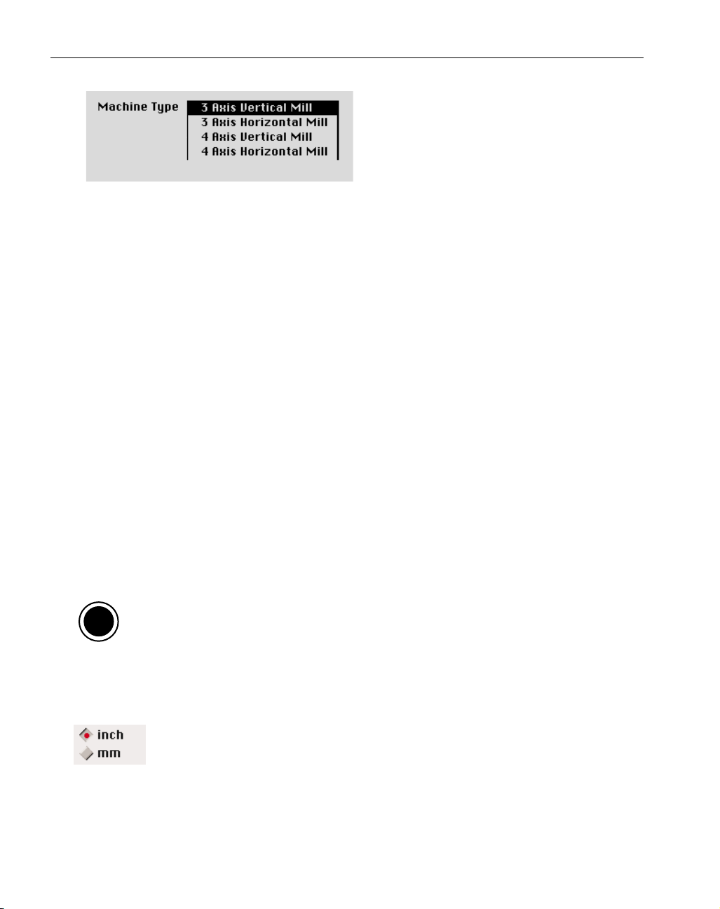
Machine Type: Clicking on the Machine Type
pop-up menu will produce a list of all machines
the system is set up to handle. The available
selections depend on which modules of the software that have been installed. There are both
horizontal and vertical selections for mills. The
shank size on the lathe selections refers to the standard tool holder size on a lathe. These shank sizes
are used to limit the number of inserts and holders in the tool database. If the Advanced Milling
module is installed, there will also be selections for four and five axis machines.
The buttons used for file management, described below, are also available under the File menu.
Open Button: Clicking on the Open button will bring up the Open Dialog which allows the user to
select which file to open. If a file is currently open, it will be closed and the selected file will be
opened.
New Button: This button will create a new file by opening a dialog and asking for a file name and a
location to save the new file. If there is a file open, it will be closed.
Save Button: If there have been any changes made while the file was open, this button will save the
changes.
Save As Button: This button will open a dialog asking for a file name and a location to save the current file. The changes made since the last Save command will be written into the new file. The original file will not be affected. The new file will become the current, open file.
Save a Copy Button: This button is very similar to the the Save As button. The system will create a
duplicate copy of the open file. The original file remains the current, open file. The name of the
duplicate file can be changed.
On Macintosh, Windows NT and Windows 95 systems, the word “copy”will be added at
the end of the file name to distinguish it from the original.
Close Button: This button closes the current file. If the file has not been saved before clicking on the
Close Button, a dialog will come up asking if the file should be saved.
Measurement Type: These two radio buttons determine whether values input will be
based on an English or metric standard and entered in inches or millimeters. The
measurement type used by the post processor is determined by the post processor
itself. There are English and metric post processors. If an English post is used on a metric part, the
posted numbers will be converted from millimeters to inches. Likewise, metric posts will convert
values from inches to millimeters.
O
S
Page 21
GFK-1703 Part Set-Up
◆
15
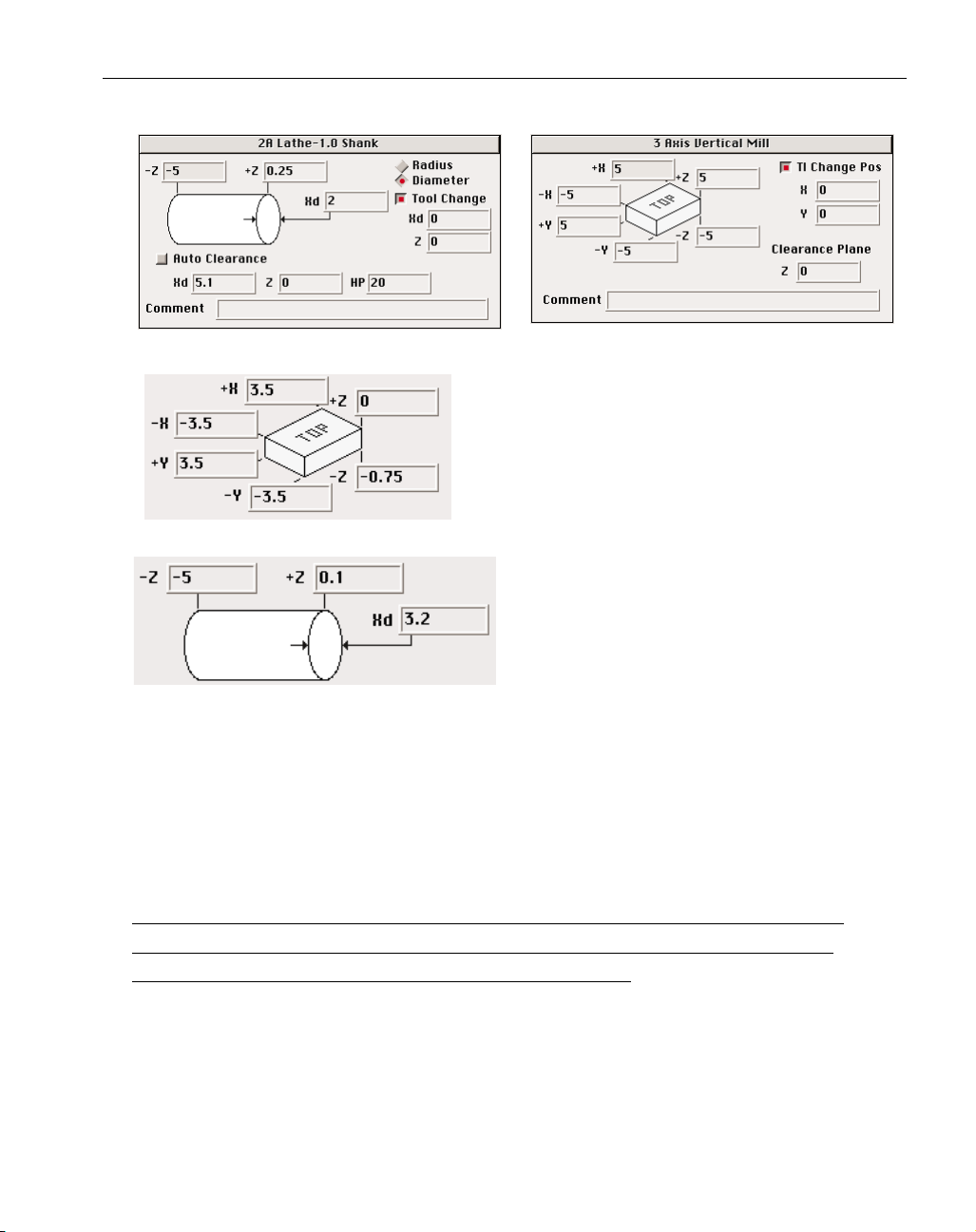
Lathe Mill
Mill Stock Size Diagram: This section of the dialog is used
to specify the starting size of the part stock. The numbers
will be used to draw the stock outline and origin marker
correctly, and to draw the stock during the rendering
process. These values will not affect the programming of
the part, but it is recommended that they closely correspond to the actual stock being used.
Lathe Stock Size diagram: This section of the dialog is
used to specify the starting size of the part stock.
The stock size entered here will be used by the system to determine positioning moves when the Auto
Clearance option is turned on, and toolpath moves
when the Material Only option is selected in a
process. If a custom stock shape has been created in
one of the workgroups, the system will use the custom stock size for toolpath and positioning
moves. In that case, the values entered here will only be used to draw the stock outline and origin
marker, correctly. The text box for the X dimension will be a radius or diameter value depending
on which option is selected for the X Dimension Style.
Comment: Any text entered as a part comment will be shown in the part preview section of the Open
dialog.
THE OTHER INFORMATION CONTAINED IN THIS DIALOG, SUCH AS CLEARANCE PLANE
VALUES AND TOOL CHANGE POSITION WILL BE DESCRIBED IN THE ACCOMPANYING
MACHINING MANUALS FOR THE LATHE AND MILL MODULE.
Page 22
◆
Geometry Creation User Manual GFK-1 7 0 3
16
CHAPTER 4
:
Geometry Creation
GEOMETRY OVERVIEW
Geometry must be created in order to machine a part. All part geometry is created using the Geometry Creation palette or imported through the Exchange option.
Creating geometry using the Geometry Creation palette can be accomplished in
three ways; using the Geometry Expert spreadsheet which combines the creation and
connection of all geometry features in one easy to use method, using the free form
CAD tools and connecting the independent features together, or using a combination
of these two.
This chapter details the different functions available for geometry creation and
provides detailed explanations of how shapes are created using the system. To gain practical
knowledge of the concepts outlined in this chapter, complete the exercises provided in the following chapters.
GEOMETRY EXPERT
Geometry Expert is a method of geometry creation which facilitates the fast creation of simple parts and the simplified creation of more complex parts, along with being very easy to learn
and use. Geometry Expert is designed to create a single, continuous, shape. It allows the user to
define, create and connect shape features while following along the path of the part.
Geometry Expert has a tabular format which operates much like a standard spreadsheet.
Features are defined by entering dimensions into the cells (text boxes) of the feature rows. Each
row creates a different feature. Features are defined in the same order as they are encountered
along the shape path.
Creating a shape using Geometry Expert is akin to “walking” around the path of the shape,
indicating such items as location, direction and the distance being traveled. While this is similar to
standard shape creation techniques, Geometry Expert goes one step further. It applies its inherent
knowledge of geometric principles and follows a logical course which allows for the creation of
complete, connected, geometrically correct shapes, requiring the least amount of input from the
user.
Geometry Expert, as the name implies, provides the user with a built-in consultant on the
rules and principles of geometry. The system makes the creation of simple parts as quick, easy,
and painless as possible. At the same time, it makes the creation of more complex parts as simple
as possible by calculating, creating and connecting shape features based on whatever part dimensions are provided.
The associative capabilities of Geometry Expert make editing any existing shape a very easy
process. The system handles the dimension changes while maintaining all the proper connections
and relationships between pieces of geometry (eg. intersections and tangencies). Geometry Expert
frees the user from needing to understand complex geometrical relationships and calculate feature
dimensions. Instead, the user can simply enter the specifications provided on the part blueprint
and let Geometry Expert do the rest.
Page 23

GFK-1703 Geometry Creation
◆
17
FREE FORM CAD
The free form CAD tools included in the system are also very powerful and easy to use.
Creating points and features is as easy as clicking on buttons and entering values. Likewise, connecting features to form shapes that can be machined simply involves selecting the intersecting
features and clicking on a button. Several different options are provided for creating points, lines,
circles, fillets, and chamfers making it possible to create any shape regardless of how the blueprint
is dimensioned. The free form CAD tools are particularly useful with parts requiring construction
geometry.
COMBINATION
Using both Geometry Expert and the free form CAD capabilities to create a part shape is a
very powerful combination. For example, a simple shaft with chamfers can be created in minutes
by using Geometry Expert to create the horizontal and vertical lines, and the automatic
fillet/chamfer option in the Geometry Creation palette to create the chamfers.
Additionally, Geometry Expert allows for the loading of any shape into its spreadsheet format. Loading an existing shape into Geometry Expert, whether it was created using Geometry
Expert, free form CAD, or imported using the Exchange option, is as easy as double-clicking on
any part of the shape while the Geometry Expert spreadsheet is open on the screen. All features of
the shape are listed and dimensioned in the rows of the spreadsheet where they can be checked
and changed. This provides the user with a quick and easy verification method and editing tool.
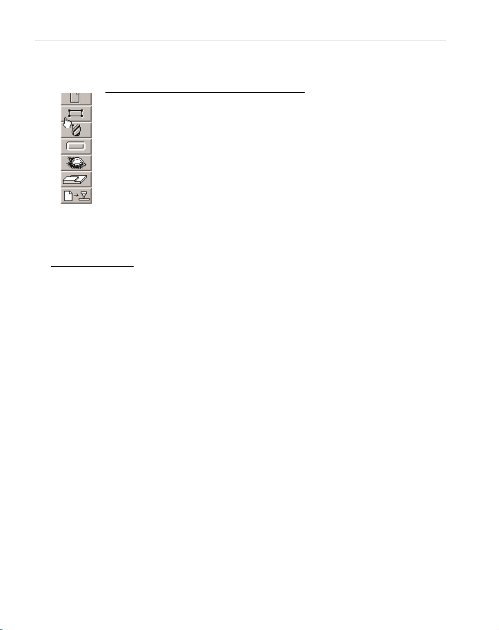
GEOMETRY CREATION PALETTE
Depressing the Geometry Creation button will bring up the Geometry Creation palette. The
Point, Line, Circle, Fillet-Chamfer and Auto-shape buttons access sub-palettes which provide various options for creating the selected type of geometry. The Geometry Expert button accesses the
Geometry Expert spreadsheet which allows the user to enter feature information and quickly
define a continuous shape. The Connect/Disconnect button allows the user to manually connect or
disconnect features. This palette also accesses different workgroups (layers) of the file and creates
new workgroups. For more information on workgroups, refer to the Workgroups section later in
this chapter.
All buttons in the Geometry Creation palette can be accessed from the keyboard by typing
the number of their position in the palette, (eg. type a 1 instead of clicking on the Point button, a 2
for the Line button, etc). The Geometry Creation palette can be moved (“dragged”) to any loca-
Spline
Button
Fillet-Chamfer
Button
Connect/Disconnect
Button
Workgroup Info
Button
Workgroup Selection
Button
Geometry Expert
Button
Coordinate System Button
(Adv. Milling only)
Title Bar
Line
Button
Auto-shape
Button
Close Box
Point
Button
Circle
Button
Page 24
◆
Geometry Creation User Manual GFK-1 7 0 3
18
tion on the screen by placing the cursor on the title bar of the palette so that the cursor changes to
the mover tool. Then, while holding down the mouse button, drag the dotted outline of the palette
to a different location, and let go of the mouse button.
When a sub-palette is open, the cursor will change to the selection cursor. This means that
any geometry that is clicked on will become part of the current selection. If the geometry is
already selected when it is clicked on, it will become deselected. This is the same as holding
down the shift key when not in a sub-palette.
GEOMETRY EXPERT
There are four general ways that Geometry Expert can be utilized as a geometry creation
tool. First, the creation of simple shapes, containing primarily horizontal and vertical lines, such
as shafts, is almost effortless using Geometry Expert. The default settings and automatic angle
toggling allow the user to create alternating, intersecting, horizontal and vertical lines in the fastest
manner possible. The user only needs to enter one value in order to define the line.
Second, the creation of more complex shapes, containing multiple arcs and angled lines, is
greatly simplified due to the fact that Geometry Expert constantly applies its built in logic and
knowledge of geometry to guide the user through the process.
Third, the user can doodle or sketch a rough part outline using the Mouse Line tool, and then
load the shape into Geometry Expert to properly dimension it. The associative capabilities of the
system will adjust the shape according the the new values entered, while still maintaining all the
correct connections and relational data to the other features of the shape.
Finally, Geometry Expert is a very powerful editing tool. Feature dimensions can be adjusted by simply changing the values in the spreadsheet. Geometry Expert handles all of the calculations and adjustments to the other features that are affected by the changes. Any shape, regardless
of how it was created, can be loaded into Geometry Expert, making it ideal for verifying and
adjusting imported IGES and DXF files, old CAD files, or frequently changing part files.
HOW GEOMETRY EXPERT WORKS
Geometry Expert is set up much like a standard spreadsheet. Feature specifications are
entered into cells which are contained in rows. Each row of the spreadsheet defines a feature.
Features are defined in the order that they appear along the path of the shape. When the
Geometry Expert spreadsheet is open on the screen the user can create fully connected shapes by
entering feature specifications in each of the rows. Because Geometry Expert creates connected
shapes, each feature is dependent on and aware of the preceding and following features.
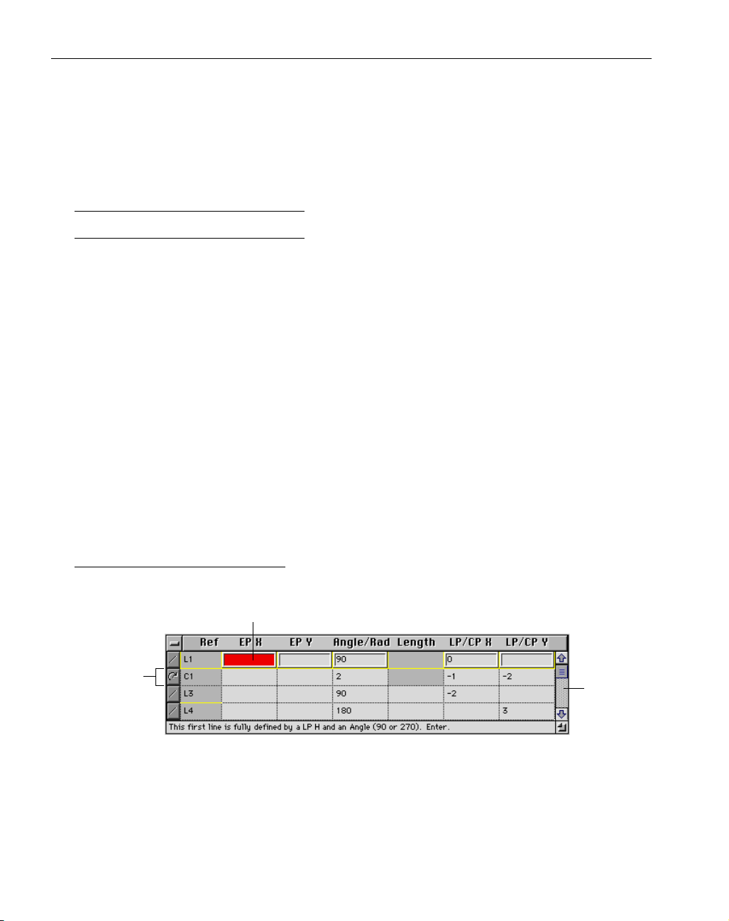
The feature row that is being worked on at any given time is referred to as the “current row”.
The current row has an upraised frame and is outlined in either yellow or black. When the current
row contains adequate information, it is outlined in yellow. The prompt at the bottom of the
Cell
Feature Row
Scroll Bar
Page 25

GFK-1703 Geometry Creation
◆
19
spreadsheet, which gives the status of the current row, will indicate what will happen when the
row is entered.
The current row will be outlined in black if it does not contain enough information. The
prompt will indicate what additional information is needed to define the row. If the user attempts
to enter a row that does not contain enough information, an error balloon will come up, again indicating what other information is required. When the current feature row contains the appropriate
information, the row is entered into the spreadsheet by hitting the enter or return key. Entering a
new row moves the cursor down to the next row in the spreadsheet, which will now be the current
row. The enter and return keys only move the current row down in the spreadsheet if a new row is
being created. Otherwise, the arrow keys or the cursor must be used to maneuver through the
rows in the spreadsheet.
Each feature is drawn on the screen as soon as the spreadsheet contains the necessary information. Some features cannot be drawn until later features are defined. These are referred to as
“floating features” and are explained later in this section.
Creating part geometry with Geometry Expert is accomplished by walking along the path of
a shape, and defining features as they are encountered. In this way, all features are automatically
connected to the preceding and following features. Because of this methodology, sometimes it is
necessary to specify the correct direction of a feature, in addition to indicating its magnitude.
For arcs, the selected feature type indicates the direction, either clockwise or counter-clockwise. For lines, the angle value indicates the direction. For example, a horizontal line can either
be defined with an angle value of 0° or 180°; both will draw the same line, but in the opposite
direction. Specifying the correct line direction is only an issue if the previous or next feature is
going to be an arc. When that is the case, it is necessary to indicate to the system what direction
the line is moving. Again, checking the line direction should only be necessary when the line is
being connected to an arc.
CREATING SHAPES USING GEOMETRY EXPERT
When creating a part using Geometry Expert, the first thing that must be decided is the starting feature and the direction to travel around the part, either clockwise or counter-clockwise.
When the spreadsheet is first opened, the first row will default to a line with an angle of 90°. The
information in this row will need to be added to and/or changed in order to define the first feature.
The prompts indicate what additional information can be entered to define the feature. As
soon as the first row contains enough information to fully define the feature, the frame of the row
will become yellow. When the frame is yellow, the prompting information tells the user how the
feature will be created. A yellow frame around the row indicates that the user can press enter
without getting an error message. Hitting enter or return will create the feature and start a new
row. The reference number of the feature that was created will be placed in the Ref cell in its row.
The new row’s feature type will default to a line, and the angle will default to either 0°/180°
or 90°/270°. The angle value of the line will automatically toggle between either 0°/180° or
90°/270°. Once again, the prompt will indicate what information can be added to further define
the line.
In this case, and many others, the frame of the row will be yellow even if the row does not
contain enough information to fully define the feature. This is because it is still possible to add
information in subsequent rows that will fully define the feature. At this point, information can be
added to or removed from the row to define the next feature of the shape as dimensioned on the
print. When the information is correct, the feature is created by hitting the enter or return key.
Page 26
◆
Geometry Creation User Manual GFK-1 7 0 3
20
This process continues until the last feature of the shape is defined. When the last feature of
the shape is created it should intersect with the first feature of the shape. At this point the feature
must be connected using the Close Shape feature type.
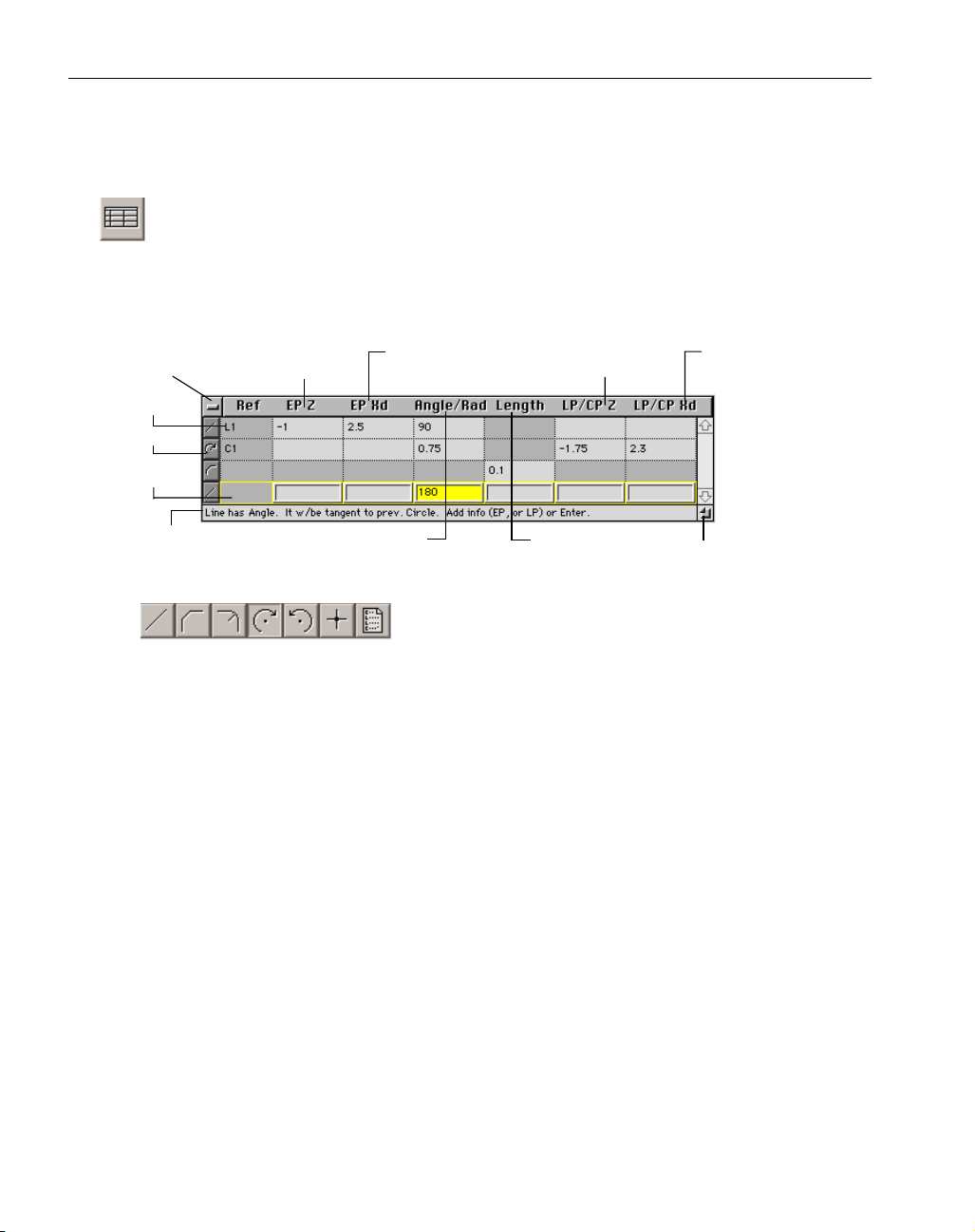
Geometry Expert button: The Geometry Expert button is located in the last position in the
Geometry Creation palette. Clicking on this button brings up the Geometry Expert
spreadsheet, shown below, which allows the user to create connected shapes by entering
feature dimensions in the rows of the spreadsheet.
Feature Type: There are seven options available for the
feature type. They are (from left to right): line, chamfer,
fillet, clockwise arc, counter-clockwise arc, close shape, and macro. Each row must have a
feature type selected. To select the feature type, click on the feature type button which will
access the possible selections. Drag the mouse to the desired feature so that the button
appears depressed, and let go of the mouse button. That feature will now appear as the
feature type for the row. In some cases, depending on the previous feature, some of the
feature type options may be grayed out to indicate they are not valid selections. Also,
depending on the feature type selected, some cells may be grayed out indicating that the
selected feature type does not require that dimension. The feature type can also be selected
using keyboard shortcuts. Refer to the Shortcuts information card or the Shortcuts Appendix
found in the Machining Module Manuals for information on keyboard shortcuts for
Geometry Expert.
Reference #: Every feature that is created is assigned a reference number by the system. The
letter indicates what type of feature it is, L for line, C for circle, and the number indicates the
creation order. These reference numbers may change during the course of creating geometry,
but will not affect the shape.
Close box
Reference #
Feature Type
Current Row
Prompt
Horizontal coordinate
of Endpoint
(Z in Lathe, X in Mill)
Angle of Line/
Radius of Circle
Vertical coordinate
of Endpoint (Xd/Xr in
Lathe,Y in Mill)
Horizontal coordinate of
Line point/Centerpoint
(Z in Lathe, X in Mill)
Length of line
or chamfer Size box
Vertical coordinate of
Line point/ Centerpoint
(Xd/Xr in Lathe,Y in Mill)
Page 27
GFK-1703 Geometry Creation
◆
21
NOTE
For lathe parts, the horizontal coordinate is a Z value, the vertical coordinate is an Xd or Xr
value. For mill parts, the horizontal coordinate is an X value and the vertical coordinate is a Y
value.
EP Z (X): The number entered in this cell is the horizontal coordinate of the endpoint of the
current feature. When a feature is defined with an endpoint, the system will draw the feature
and trim it at the specified endpoint. Endpoint specifications are required if the next feature
needs a start point in order to be correctly defined.
EP Xd/Xr(Y): The number entered in this cell is the vertical coordinate of the endpoint of the
current feature.
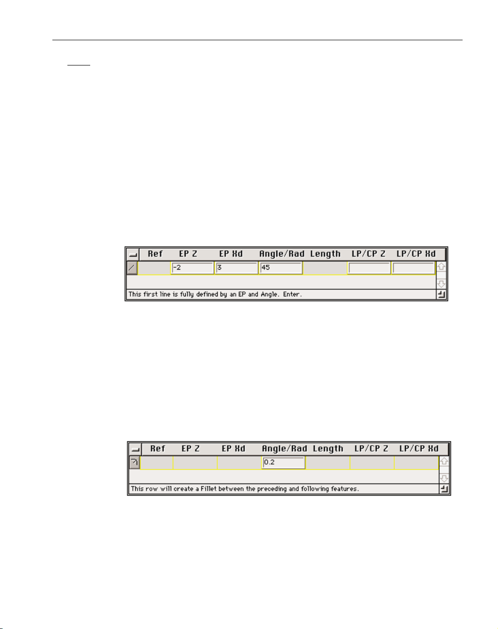
EXAMPLE: The row shown below will create a 45° line with an endpoint drawn at
Z -2, Xd 3. The next feature that is defined in the spreadsheet will start at the end
point of this feature.
Angle/Rad: The number entered in this cell is dependent on the feature type selected.
If the feature type is a line, this number specifies the angle of the line. The angle value for a
line defaults to either 90°/270° or 0°/180° allowing for the creation of vertical or horizontal
lines, respectively. The system toggles between these angle values which makes the creation
of intersecting horizontal and vertical lines a very quick and easy process. The user can
change the default values by simply entering the new numbers in the cells. If the feature
type is a arc or fillet, this number specifies the radius.
EXAMPLE: The row shown below will create a fillet between the previous and following feature with a radius of 0.2.
Length: The number entered in this cell is the length of the current feature. The length cell
is only active if the feature type is either a line or a chamfer.
Page 28
◆
Geometry Creation User Manual GFK-1 7 0 3
22
LP/CP Z (X): The number entered in this cell is dependent on the feature type selected.
If the feature type selected is a line, this number is the horizontal coordinate of a line point
(LP). A line point is simply any point that lies somewhere on the line. Line points are only
used to draw and calculate the line, they are not part of the shape. Line points are not drawn
on the screen. Geometry Expert defaults to the LP/CP cell so it is more efficient when
creating lines to use line points whenever possible in order to reduce the number of key
strokes necessary. If the feature type selected is a circle, this number is the horizontal coordinate of the centerpoint of the circle.
LP/CP Xd/Xr (Y): The number entered in this cell is dependent on the feature type selected.
If the feature type selected is a line, this number is the vertical coordinate of a line
point. If the feature type selected is a circle, this number is the horizontal coordinate of the
centerpoint of the circle.
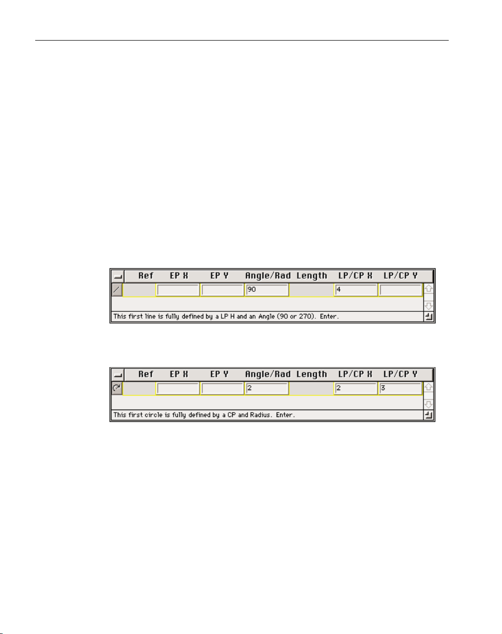
EXAMPLE: The row shown below will create a 90° (vertical) line that goes through
the point at X 4. When defining either horizontal (0°/180°) or vertical (90°/270°)
lines, only one LP coordinate is required. Refer to the section on Half Points in this
chapter for more information.
EXAMPLE: The row shown below will create a circle with a radius of 2 and a
centerpoint at X 2, Y 3.
Prompt: The information contained in the prompt indicates the status of the current row.
When a feature row is outlined in yellow, the prompt tells the user what specifications have
been entered for this feature and what will happen when the row is entered. If the feature row
is outlined in black indicating that more information is required, the prompt will tell the
user what additional information is required. The prompt also indicates if the system has automatically deleted a cell value because the feature row contained too much information that
overdefined the feature. This aspect of Geometry Expert is referred to as the “auto delete”
function which is explained in the Expert Aids section of this chapter.
Page 29

GFK-1703 Geometry Creation
◆
23
Close box: Clicking in this box will close Geometry Expert and allow the user to use the free
form CAD tools contained in the Geometry Creation palette. When Geometry Expert is closed,
all information is cleared out of the spreadsheet. When the Geometry Expert button is
depressed again, the spreadsheet will come up empty. In order to load or reload a shape into
the spreadsheet, simply double click on any feature of the shape while the spreadsheet is open
on the screen.
Size box: The size box allows the user to adjust the size of the Geometry Expert spreadsheet.
To adjust the size of the spreadsheet, click in the Size box and drag the window to the desired
size. The width cannot be changed, but the length can be adjusted.
Scroll Bar: The scroll bar and arrows allow the user to scroll through the rows contained in
the spreadsheet to make adjustments and check the values entered. This is useful if the spreadsheet needs to stay relatively small to fit on the screen, and/or if it contains many features.
EXPERT AIDS
There are several items built in to Geometry Expert that are designed to guide the user
through geometry creation. They include prompting, auto delete, and error balloons.
Prompting
The prompting information appears across the bottom of the Geometry Expert spreadsheet.
The prompt tells the user what actions are being taken by the system based on the information provided by the user. The user should be able to follow the prompts through the creation process to
get a good idea of what is happening.
Auto Delete
The auto delete function of Geometry Expert is intended to reduce errors resulting from features being overdefined because too much information has been entered in the feature row.
Geometry Expert is designed so that the user need only enter the minimum amount of information
to define a feature. The system will automatically delete the first entry made in the feature row
when the feature is overdefined. Auto delete is necessary in order to facilitate the associative
capabilities of Geometry Expert. Note that the default values, such as the line angle, are considered the first entry rather than any information entered by the user. The prompt will indicate what
information is being deleted.
Error Balloons
Geometry Expert also contains Error Balloons which appear on the screen whenever a problem occurs. The most common error messages appear when the system requires more information
for a feature being entered. For example, if a line needs another value for an end point, an Error
Balloon will come up indicating that a V or H value is needed to calculate the end point. The
Error Balloons and Prompting use the letters V and H, indicating Vertical and Horizontal, rather
than using X and Y (for Mill) or Xd/Xr and Z (for Lathe.) This way the error messages remain the
same regardless of what module is being used.
Another common error message indicates that the feature being defined cannot intersect with
the previous feature. The non-intersecting feature can still be created, but the message indicates to
Page 30

◆
Geometry Creation User Manual GFK-1 7 0 3
24
the user that the continuity of the shape has been broken and the subsequent features being created
will not connect to the existing shape.
ADDITIONAL INFORMATION
Defaults
When entering features in the Geometry Expert spreadsheet, the system contains defaults for
the feature type and line angle. The standard feature type default is a line. When Geometry
Expert defaults to a line, it also enters an angle value, either 90°/270° or 0°/180°, depending on
the angle of the last line entered. Sometimes a line is not a possible feature type option, in which
case the system defaults to an arc. This only occurs when the previous feature is a floating line.
Geometry Expert dimensions the line according the preceding and following feature specifications.
Floating features are not drawn on the screen until the system contains the necessary information.
Post Targeting
Despite all of its expertise, Geometry Expert can’t always know the correct intersection point
to use for a connector. When there are two or more, equally valid points of intersection, the system will draw both points. This is referred to as post targeting. When post targeting is required, a
dialog will come up that asks the user to select the appropriate point and click on the OK button.
Once the user has selected the desired intersection point, Geometry Expert will make the appropriate connection and continue along in the spreadsheet defining and connecting features.
The Edit menu contains an item that will change the intersection point selected in a post targeting dialog to the other possible point of intersection. The menu item toggles between Use
Intersection #1 and Use Intersection #2, depending on the point selected and where it lies along
the path of the shape. This option will be an active item when a feature that required post targeting is selected on the screen.
Half Points
In certain cases, only one coordinate, either the horizontal or vertical, is required to define
the feature. This is referred to as a half point case. Half points are valid when Geometry Expert is
able to calculate the other half of the coordinate value from information contained in the spreadsheet. (Either preceding or following features.)
When a valid half point is entered, the row will be highlighted in yellow, allowing the user to
enter the feature row. If the half point entered is not valid, the row will be highlighted in black
and the prompt will indicate what additional information is necessary to enter the row. If an
incomplete row is entered, an error ballon will come up indicating what additional information is
required. There are three cases where half points are valid. They are listed and explained below.
Half Line Point: A half line point is valid only when creating either a horizontal line (angle
value = 0° or 180°) or vertical line (angle value = 90° or 270°). If creating a horizontal line, a
V coordinate must be given for a valid half line point. If creating a vertical line, an H coordi-
nate must be given for a valid half line point. Line points are not part of the shape, but are
only used to calculate the position of the line.
Half End Point: A half end point is only valid if the line is otherwise completely defined.
Given either the vertical or horizontal coordinate of the end point along with the other informa-
tion that defines the line, the system can calculate the other half of the end point. If a half end
point is used in the case of 0°/180° or 90°/270° lines, the half end point will function like a
half line point, in that an end point will not be drawn, although the correct line will be created.
Page 31

GFK-1703 Geometry Creation
◆
25
Half Center Point: A half center point is valid when a circle has a radius value and is tangent to
the preceding feature. (There must be a preceding feature.) Given the radius and the vertical
or horizontal component of the centerpoint, the system can calculate the other half of the
centerpoint by the assumed tangencies.
Floating Features
Floating features are features whose defining row does not contain all of the information necessary to draw the feature. Floating feature rows are different from incomplete feature rows. With
floating feature rows, the information contained in the current feature row and the preceding rows
is inadequate to completely define the feature and draw it. However, subsequent features, defined
in following rows, should provide the necessary information to define the floating feature.
Floating feature rows are outlined in yellow and can be entered.
Incomplete feature rows do not contain enough information to create the feature, and no
amount of information entered in following rows will make the feature definable. Incomplete feature rows are outlined in black and cannot be entered without getting error messages.
Again, the row outline and the prompting information will indicate if the feature row can be
entered, and if it is, how the floating feature will be incorporated into the shape after later features
have been defined.
Inserting and Deleting Rows
The Edit menu contains options for inserting and deleting rows in the spreadsheet. When
inserting rows in the spreadsheet, the system will create a new row above the current row. To
insert a row, select the row beneath the row to be inserted. Then, select the Insert row option in
the Edit menu. When an inserted row is entered, the system will recalculate the shape and attempt
to incorporate the new feature into the existing shape, if possible.
To delete a row, simply select the row to be removed, and choose the Delete Row option in
the Edit menu. When rows are deleted, Geometry Expert will recalculate the shape, and attempt
to keep it continuous and connected. If that is not possible, error balloons will appear indicating
that features do not intersect and the shape cannot be connected.
Arcs vs. Fillets
Arcs with only a radius value and fillets appear to be very similar at first glance, but actually
use two completely different methods for calculating the circles. A fillet takes a sharp point produced by an intersection between two other features and changes it into a radius. It is created after
the intersection between the two features is completed. Because of this, it is dependent on the
intersection of the other two features to exist. This means that the system cannot use the fillet to
calculate features that follow it in the spreadsheet. As the prompts indicate, Geometry Expert
completely ignores fillets (and chamfers) when calculating what information is necessary to define
features. When the prompt displays information about the interaction between the current feature
and the previous feature, fillets will be ignored.
An arc with only a radius value is created tangent to two other features. These two features
do not have to intersect. The arc is treated as an actual feature and can be used when calculating
other features of the shape.
This is particularly important when dealing with floating lines (lines with limited information) that have specific tangency requirements. Geometry Expert assumes that floating lines are
going to be made tangent to the preceding feature. In most cases this is adequate, but sometimes a
Page 32

◆
Geometry Creation User Manual GFK-1 7 0 3
26
floating line is supposed to intersect the previous circle and be tangent to the next circle. This is
called a "forward" tangency.
In the case of forward tangencies, if there is a radius between the previous circle and the
floating line, then an arc, rather than a fillet, must be used in order to allow for the necessary tangency calculation. The line will be made tangent to both the arc used as a fillet and the next arc.
A fillet cannot be used in this case because the fillet will be ignored by the system until the intersection is completed, and the correct intersection cannot be created without the arc. If there is no
fillet, an arc with a radius of zero will need to be created. This will allow the system to create the
line tangent to the following circle, while creating a sharp point at the intersection of the previous
feature.
For a practical example of forward tangencies, refer to Exercise # 3 in the Combination
Exercises Chapter.
FREE FORM CAD
The free form CAD tools are contained in the Geometry Creation palette. The buttons in the
palette access sub-palettes and dialogs that allow the user to enter feature specifications and create
shapes. The buttons, sub-palettes and dialogs are described below.
Point button: Clicking on this button brings up the Point sub-palette, shown below, which
consists of a group of buttons containing the construction tools for creating points.
Point sub-palette: This sub-palette con-
tains buttons which allow the user to
create points in 3D space in a variety
of ways. When each is depressed,
a geometry dialog appears on the
screen. Geometry dialogs are used for input of specific geometric (numerical) information in
the creation of points and features. If two features are selected before the Point button is
depressed, the Point sub-palette will be skipped and a dialog providing for the creation of a
point between the two features will appear instead. Likewise, once the Point button has been
depressed, two features can be selected without depressing a button of the sub-palette, and a
dialog will automatically appear allowing for the creation of a point between the two features
selected. If only the Lathe module is installed, the Bolt Circle button and the Matrix Point but
ton will be grayed out because they have no applications in lathe.
XYZ button: Create a point by typing in the coordinate values for the point.
For Mill, X,Y, and Z coordinates. For lathe, Xd or Xr (depending on the X
Dimension style) and Z coordinates.
Polar Point button: Create a point at some angle and distance from an existing
point.
Page 33

GFK-1703 Geometry Creation
◆
27
Bolt Circle Point button: Create a circular pattern of points by entering the
appropriate information in the dialog shown below.
Matrix Point button: Create a parallelogram pattern of points by entering the
required information in the dialog shown below.
Centerpoint button: Create a point at the center of an existing circle.
Mouse Point button: Create a point wherever the cursor is clicked with a user-
defined grid spacing.
Return button: This button appears at the far right end of geometry sub-
palettes and dialogs, and returns the user to the Geometry Creation palette.
It can also be activated by hitting the escape key on the keyboard.
X Coordinate of
Pattern Centerpoint
Y Coordinate of
Pattern Centerpoint
Radius of
Circle Pattern
Z Depth
of Points
Creation Order Direction
(CCW or CW)
Angle to 1st Point
# of Points
in Pattern
Side 1
Change in X
Side 1
Change in Y
# of points
in Side 1
Y Coordinate
of 1st Point
X Coordinate
of 1st point
Side 2
Change in Y
Side 2
Change in X
Z Depth
of Points
# of Points
in Side 2
Page 34

◆
Geometry Creation User Manual GFK-1 7 0 3
28
Line button: Clicking on this button brings up the Line sub-palette, shown below, which provides for the creation of lines.
Line sub-palette: This sub-palette con-
tains buttons which provide different
methods to create lines. All buttons in
this palette are active choices. If
two features and/or points are selected before the Line button is depressed and those points
and/or features can have a line created through or tangent to them, the Line sub-palette will be
skipped and a dialog asking to create a line between the two features and/or points will appear
instead. Likewise, once the Line button has been depressed, two features and/or points can be
selected without depressing a button of the sub-palette, and a geometry dialog will automatically appear allowing for the creation of a line between the two features and/or points selected.
Point-Angle button: Create a line through an existing point at some specified
angle.
Tangent-Angle button: Create a line tangent to an existing circle at some speci-
fied angle.
Parallel Line button: Create a line parallel to an existing line at some specified
distance.
Perpendicular Line button: Create a line perpendicular to an existing line
through a specified point.
Parallel to Axis button: Create either a horizontal or vertical line, parallel to
an axis, at a specified distance from the axis.
Mouse Line button: Create connected lines using the mouse. Endpoints will be
made whenever you click on the mouse button, and will snap to a predefined grid of the users choice.
Circle button: Clicking on this button accesses the Circle sub-palette, shown below, which
provides options for the creation of circles.
Circle sub-palette: This sub-palette con-
tains a group of buttons for creating
circles. If two features and/or points
are selected before the Circle button is
depressed and those points and/or features can have a circle created tangent to them, the Circle
sub-palette will be skipped and a dialog asking to create a circle tangent to the features and/or
points will appear instead. Likewise, once the Circle button has been depressed, features
and/or points can be selected without depressing a button of the sub-palette, and dialog will
automatically appear allowing for the creation of a line between the two features and/or points
selected.
Page 35

GFK-1703 Geometry Creation
◆
29
Centerpoint-Radius button: Create a circle using a selected point for the centerpoint and defining a radius.
Centerpoint-Circumference button: Create a circle by choosing a point for the
centerpoint and another as a point on the circumference of the circle.
Three Elements button: Create a circle by selecting any combination of three
points, lines or circles for the circle to intersect or be tangent to.
Auto-shape button: Clicking on this button brings up the Auto-shape sub-palette which provides options for automatically generating shapes including text, rectangles, and polygons.
Auto-shape sub-palette: This sub-palette
provides options for quickly creating
text, rectangles and polygons. Each
button in the sub-palette accesses a
dialog specific to the type of shape
that will be created.
Text Creation button: This button accesses the Text Creation dialog which creates spline geometry from any TrueType font. For more information on Text
Creation refer to the Text Creation section later in this chapter.
Rectangle button: This button accesses the Rectangle dialog which creates rectangles and squares.
Rectangle dialog: This dialog specifies the length of
each side of the rectangle
and the center position of
the shape. There is also a
radio button at the bottom
of the dialog which
allows the user to specify
a fillet radius which will
be added at each corner
of the shape. Clicking on
the Process button creates
the defined shape.
Page 36

◆
Geometry Creation User Manual GFK-1 7 0 3
30
Polygon button: This button accesses the Polygon dialog which creates multi-
sided shapes (polygons).
Polygon dialog: This
dialog specifies the
number of sides, the
center position, the distance from the centerpoint to either the flat
side or the corder.
There is also a radio
button at the bottom of
the dialog which
allows the user to specify a fillet radius which
will be added at each
corner of the shape.
Curve button: Clicking on this button accesses the Curve sub-palette which provides options
for creating curves through a series of selected points.
Curve sub-palette: This sub-palette pro-
vides three different methods for cre-
ating curves through a series of pre-
defined points. Those methods
include Line Fit, Curve Fit, and Control Point. The Curve sub-palette changes in appearance
depending on the selected creation method. For more information on Curve Creation refer to
the Curve Creation section later in this chapter.
Fillet-Chamfer button: When this button is depressed, the Fillet-Chamfer sub-palette appears
on the screen. The options available in this menu can only be used on fully connected
points. Normally the button is grayed out, however, when a point(s) is selected, the button becomes black and allows the user to access the sub-palette. If the point is not a connector
point the sub-palette will come up on the screen, but no fillets or chamfers will be created.
Multiple fillets and chamfers can be created at one time by using this option when multiple points
are selected.
Fillet-Chamfer sub-palette: This subpalette provides options for creating
fillets and chamfers. The first button
provides for the creation of fillets.
The remaining three buttons allow
the user to create chamfers by specifying the chamfer size using different methods of defin
ition. The pictures on the chamfer creation buttons clearly display the meaning of the value
entered for the chamfer size.
Page 37

GFK-1703 Geometry Creation
◆
31
Fillet button : Create a fillet by selecting a connector point(s), entering a
radius value and clicking on the single circle button.
Chamfer-Side button: Create a chamfer by selecting a connector point(s),
entering a side value and clicking on the single line button.
Chamfer-Depth button: Create a chamfer by selecting a connector point(s),
entering a depth value and clicking on the single line button.
Chamfer-Length button: Create a chamfer by selecting a connector point(s),
entering a length value and clicking on the single line button.
Connect/Disconnect button: This button does not access any sub-palettes or dialogs. It
becomes an available option (black instead of gray) when a point is selected. To change a
plain point to a connector point, the point and the two features that intersect at that point
must be selected prior to clicking on this button. To disconnect or break a connection, only the
point needs to be selected prior to clicking on the button. Refer to the Shapes and Connectors section in this chapter for details.
TEXT CREATION
The system contains the capability to generate geometry from any TrueType®font. The Text
Creation Dialog is accessed from the Auto-shape sub-palette by clicking on the Text Creation
Button.
Text Creation Dialog : The Text
Creation Dialog allows the user to
select the typeface, text size, justification, position, spacing between
characters, words and lines, and text
flow. The Text Creation Dialog contains tabs that access different windows available in the dialog which
include Text, Spacing and Text Flow.
The Process button and the Text
Entry box (bottom portion of the
dialog where text is entered) remain
available regardless of which tab
window is currently being viewed.
Page 38

◆
Geometry Creation User Manual GFK-1 7 0 3
32
Text Tab Window : The specifications
entered in this window establish what
the text will look like and where it
will be positioned on the part.
Typeface Pop-Up Menu : This menu designates the typeface that will be used
to create the text. Only TrueType fonts (typefaces) can be used to
create geometry from text. All TrueType fonts installed on the system will be available in this
pop-up menu.
Text Size : This value specifies the height (measured in either inches or
millimeters) of a capital ‘A’ in the selected typeface. All other characters
will be sized proportionally.
Justification : These buttons specify whether the text should be left justified,
centered or right justified. If left justified is selected, all text is aligned so
the left edge of each line is in the same X location, or if radial is selected,
the same angle. If centered is selected, the center of each line of text is calculated and the text
is positioned so the centers all share the same X location or angle. If right justified is selected,
the text is aligned so the right edge of each line is in the same X location, or if radial is selected, the same angle. Justification will only have an affect if there is more than one line of text.
The longest line of text is used to specify the left or right edge, or the center. All text is then
aligned based on one of these locations.
Straight Text Alignment : Text can either be created in
a straight line or along an arc. This is designated in
the Text Flow window which is described later in
this section. If straight text is created, a rectangular
area that will contain the text is used for positioning.
The diagram specifies how the text will be posi-
tioned within the rectangular text area based on the
coordinates of the Alignment Point. For example, if the position highlighted in the diagram
shown above is selected, the text will be positioned in the lower left corner of the rectangular
text area at the Alignment Point. The bottom of the text will be at the Y value of the Alignment
Point and the left edge of the text will be at the X value of the Alignment Point. Clicking on
the circular position points selects the different possible alignment locations.
Page 39

GFK-1703 Geometry Creation
◆
33
Radial Text Alignment : If text is created along an
arc, a radial area that will contain the text is used
for positioning. The radial text area is created by
entering an angle value that specifies where along
the arc the text will begin and a radius that specifies the size of the arc. The Center Point coordi-
nates specify the center point of the arc. The
diagram specifies how the text will be positioned within the radial text area. Examples with the
Radial Text Alignment information and the resulting text are shown below.
EXAMPLE 1: Inner Radius/Start on Angle
The picture shows the text as well as the arc and line which designate
the radial text area and the starting location of the text. The position
selected on the diagram will create the text along the outside of the circle beginning at the line specified by the angle. (The circle and line are
drawn only to better visualize the example.)
EXAMPLE 2: Center Radius/Center on Angle
The picture shows the text as well as the arc and line which designate
the radial text area and the starting location of the text. The position
selected on the diagram will create the text along the centerline of the
circle and the center of the line of text will lie along the line specified by
the angle.
EXAMPLE 3: Outer Radius/End on Angle
The picture shows the text as well as the arc and line which designate
the radial text area and the starting location of the text. The position
selected on the diagram will create the text along the inside of the circle
ending at the line specified by the angle.
Page 40

◆
Geometry Creation User Manual GFK-1 7 0 3
34
`
Text Entry Box: This box con-
tains the text that will be created in the current workgroup
according to the specifications
entered in the tab windows.
The Text Entry Box is always at the bottom of the Text Creation Dialog regardless of what
window is open. Multiple lines of text should be separated with a carriage return. Regardless
of the typeface selected in the Typeface pop-up menu, the text shown in this box will be displayed in the Chicago typeface.
Process Button : Clicking on the Process button will create geometry from the text
entered.
Spacing Tab Window: The specifications entered in this window allow
the user to enter additional spacing
distance between characters, words
and lines of the text. The system
automatically spaces the text and
lines. If values are entered in this
window, the values entered will be
ADDED to the standard spacing.
Text Flow Tab Window: The specifications entered in this window designate the text flow, line flow and
shape of the text.
Text Flow buttons : Text can either be created horizontally or vertically. The first two buttons create text (characters) that will flow along a
horizontal line, either from left to right (1st button) or right to left
(2nd button). The last two buttons will make the text flow along a ver-
tical line, either from bottom to top (3rd button) or from top to bottom (4th button).
Page 41

GFK-1703 Geometry Creation
◆
35
Shapes buttons: These buttons designate whether the text will be created in
a straight line or on an arc. (These buttons will change in appearance
when creating vertical lines of text, but their functionality remains the
same). The first button will make the text flow along the arc specified in
the Text tab window in a clockwise direction. The middle button creates text in a straight line,
and the third button creates text on an arc in a counter-clockwise direction. The selection made
for Shapes will affect the Alignment Diagrams in the Text tab window.
Lines buttons : These buttons only have an effect if multiple lines of text are
being created. (These buttons will change in appearance when creating vertical lines of text, but their functionality remains the same). The first button
specifies that the lines flow from bottom to top for horizontal lines of text or
from left to right for vertical lines. The second button specifies that horizontal lines of text
flow from top to bottom or vertical lines flow from right to left.
CURVE CREATION
The Curve Button accesses the Curve Creation sub-palette, shown below, which provides three
different methods for creating a curve through a series of pre-defined points. Those methods
include: Line Fit, Curve Fit and Control Point. Each method is described below. The Curve Creation
sub-palette changes in appearance (some items are hidden) depending on the curve method. The
curve will travel through the points in the order they were selected. The Sort item in the Modify
menu can be used to sort the points in the correct order to create the desired curve.
CURVE CREATION SUB-PALETTE
Line Fit: This method creates straight lines between the selected points. If a Tolerance is
specified, any points that are co-linear within the specified tolerance will be approximated
by a single line, rather than several small lines between the points. If Close Shape is turned
on, the system will create a closed shape, meaning that the first and last lines will be connected. The
Blending Method Pop-Up Menu is not applicable when using the Line Fit method.
Curve Fit: This method creates a B-Spline curve through the selected points. The Tolerance
value is designed to reduce the mathematical complexity of the finished curve and should
only be larger than 0 when generating curves from a large number of points. When a 0 tolerance is used the system will create a smooth curve that passes through every selected point. When
a value larger than 0 is used, the system uses a different method to produce the curve, and any
Curve Fit Button
Line Fit Button
Close Shape Button Blending Method
Control Point Button Tolerance
Pop-up Menu
Page 42

◆
Geometry Creation User Manual GFK-1 7 0 3
36
points that lie within the tolerance specified will be skipped. Even if no points lie inside the tolerance, a completely different curve will be generated by the system than if a 0 tolerance was used.
The curve generated by 0 tolerance will be smoother than a curve generated by a non-zero tolerance.
If Close Shape is turned on, the system will create a closed, continuous shape. The Blending
Method choices control how the curve will be approximated through the selected group of points.
There are an infinite number of possible curves that can be drawn between a series of points. The
way the curve is calculated between the points is based on the blending method selected from the
Blending Method Pop-up menu.
The system provides four options for the blending method. They are Chord Length, Uniform,
Foley’s and Centripetal. One way to explain the differences between these blending methods is to
imagine a point traveling along the curve being created. The difference between methods is how
much time the point spends traveling along the curve between the points that define the curve. The
Chord Length and Uniform methods are general curve calculation methods. The Foley’s and
Centripetal methods are based on the Chord Length and Uniform methods and attempt to create a
closer approximation of the desired curve. Each blending method is described below.
Chord Length: This method creates a curve between points proportional to the
distance between points. That is, the farther apart two points are, the "longer
time" it spends traveling between them, which is why it creates wider curves.
The closer two points are together, the curve flattens out, because "less time" is
spent traveling between the points.
Uniform: This method attempts to create curves of equal length between points
of equal distance from each other.
Foley's: This method takes into account the angle between adjacent points. The
larger the angle, the "more time" is spent between the points, causing the curve
to be less pointed than the Uniform method.
Centripetal: This method is based on the Chord Length method. It uses the calculated square root of the Chord Length method to blend the curve between the
selected points. This makes for a slimmer curve.
Control Point Fit: This method produces a B-spline curve using the selected points as control
points. When using control points, only the first and last point must actually lie on the
curve. The other points are used to specify the shape and direction of the curve. The Close
Shape, Tolerance and Blending Method specifications are not applicable when using the Control
Point Fit Method.
Page 43

GFK-1703 Geometry Creation
◆
37
ACCURACY PREFERENCE
Accuracy Preference: Preferences are located in the
Preferences submenu under the File menu. This preference
is used when working with curves. When curves are
machined, the toolpath breaks up the curve into line segments that can be cut by the CNC machine. The Machining
tolerance specifies how much the line-segmented toolpath
can deviate from the true curve. The other specification is
used when higher order curves are imported into the system. The system supports and is optimized for the creation
of cubic order curves. Higher order curves can be imported.
The value in the second box specifies the number for line
segments that will be drawn to create the curve. For a
smoother curve drawing, enter a larger number. For the
curve to be drawn faster, enter a smaller number. This value only affects the drawing resolution of
the curve, not the machining. The machining is controlled by the Machining tolerance.
WORKGROUPS
Workgroups are used as layers to separate different sets of geometry. The user can view
more than one workgroup at a time, or only view the current workgroup that is being worked in.
The viewing, selection and creation of workgroups is accomplished using buttons in the Geometry
Creation palette. The workgroup buttons are explained below.
Workgroup Info button: This button is found in the right hand corner of the Geometry
Creation palette. When it is depressed, a dialog comes up which allows the user to enter
a comment about the workgroup. The text entered for the Comment will appear in the Workgroup
Selection dialog next to the number of the workgroup it describes. The comment also appears in
the Workgroup Selection pop-up menu, and across the top of the Geometry Creation palette.
The picture on the left is the Workgroup Info dialog for the Milling module. If the Advanced
Milling module has been installed, the WG machining CS pop-up menu will be black and active,
allowing the user to select the machining coordinate system for the current workgroup. If the
Advanced Milling module has not been installed, the pop-up menu will be grayed out.
The picture on the right is the Workgroup Info dialog for the Lathe module. In addition to
entering a comment, the user can specify whether the geometry contained in the selected workgroup is part geometry that will be machined or a custom stock outline. The Fixtures option will
be implemented in future versions of the software. If the Part Stock option is selected, the geome-
try drawn in the workgroup will be used for any calculations that need to look at the stock dimensions, such as Auto Clearance and Material Only. Additionally, the custom part stock will be
used when the part is rendered.
Page 44

◆
Geometry Creation User Manual GFK-1 7 0 3
38
Mill Lathe
Workgroup Selection button: When this button is clicked on, the Workgroup Selection dia-
log, shown below on the left, appears on the screen. This dialog lists the workgroups of
the file being worked on, and also allows the user to create new workgroups. The name of the
current workgroup is highlighted. To switch workgroups, click on the name of the desired workgroup. To create a new workgroup, click on the New Workgroup choice at the bottom of the list.
The eye to the left of the workgroup will be open if a workgroup is being viewed. The eye next to
the current workgroup is always open. Double-clicking on a closed eye next to another, non-current workgroup will cause that workgroup to be viewed as a background workgroup. Geometry
from background workgroups is drawn in gray and cannot be selected. Double-click on an open
eye to hide the workgroup.
This button also accesses a pop-up menu, shown below on the right, which allows the user
to quickly and easily change the current workgroup. The pop-up menu can be accessed by holding the Workgroup Selection button down with the mouse. When the current workgroup is
changed, any background workgroups being viewed will stay on the screen as background workgroups.
Show Selected WG: This item is found in the View menu and allows for the selection of multiple
workgroups to be viewed as background workgroups. The eye icons in the Workgroup Selection
Dialog, shown below, are used to view workgroups as background workgroups and to change the
current workgroup.
Page 45

GFK-1703 Geometry Creation
◆
Holding down the shift key and clicking on multiple eyes, as shown in the picture above to the left,
allows more than one workgroup to be selected. When the desired workgroups are selected, choose
the Show Selected WG menu item to have them viewed as background workgroups. All the eyes will
be open, as shown in the picture above to the right, indicating that those workgroups will be viewed
as background workgroups. Using the Select All item in the Edit menu will select all of the eyes
(workgroups). A range of eyes (workgroups) can be selected by holding down the appropriate modifier key and clicking on the first and last eye of the group. All eyes in between will be selected. This
item and the Hide Selected WG item are especially useful when working with imported IGES and
DXF files with many layers.
On Windows NT and Windows 95/98 systems, hold down the Control key to select a range of
workgroups. (If Alternate Shortcuts is selected in the Interface Preference, use the Alt key.) On
Macintosh systems, hold down the Command (
"
) to select a range of workgroups.
Hide Selected WG: This item operates in the same manner as the Show Selected WG item, except that
it allows multiple workgroups to be hidden (not drawn on the screen). The same methods of selection used for the Show Selected WG item apply.
SHAPES AND CONNECTORS
Machining a part using the system requires that part geometry be contained in the part file. In
order to drill holes or thread mill, position information (points) must be defined. In order to cut a
contour, rough and finish an OD/ID, or cut a thread, a shape (lines and circles) must be defined so
that the tool has an outline to follow. To cut a pocket, a closed shape must be defined.
There are two types of shapes: open shapes and closed shapes. An open shape is a group of
connected features. There is a definite beginning and end to the shape. The two ends may or may
not be terminated. A closed shape is a group of connected features in which there is no end or
beginning. A circle is the most simple example of a closed shape. Double-clicking on a feature in a
closed shape will select all of the features and points in the shape.
Open Shape Closed Shape
39
Page 46

◆
Geometry Creation User Manual GFK-1 7 0 3
There are two classifications of geometry used by the software; features and points. Lines, cir-
cles and curves are features. Points are points.
POINTS
A point has three states. It can either be a plain point, a connector point, or a terminator point.
A plain point is used for constructing other geometry or it can be turned into a connector or
terminator. Plain points can also be used as positioning information for drilling or thread milling
operations. Points are drawn as yellow circles.
A connector is used to connect two features together. It is drawn as a blue square.
A terminator is used to end a shape. It is drawn as a yellow square.
FEATURES
A feature is either a line or a circle. A feature also has three states: unconnected, connected but
not trimmed, and connected and trimmed. A feature can have a maximum of two connectors and/or
terminators attached to it. When the second connection has been added to a feature, it will change
colors and become trimmed.
Unconnected features are drawn in yellow. They are used either for constructing additional
geometry or can be connected to other geometry to form a shape to be machined. Single features
(one line or one circle for example), drawn in yellow, can be machined by the system without being
connected to any other features or having any connection points.
Connected, but not trimmed, features are features that have only one connection to another
feature. The feature will not be trimmed until a second connection is added, or it is terminated. It
will still be drawn in yellow.
Connected and trimmed features are drawn in blue. They have been connected (or terminated) at both ends. Since they already have two connections on them, no additional features can be
connected to them.
MAKING CONNECTIONS
Most connections are made automatically by the software. If the Point button is chosen on the
Geometry Creation palette and two features on the screen are selected, the software will automatically create a connector at the intersection or tangency of the two features. If a connection cannot
be made automatically, a plain point will be created at the intersection or tangency of the two features. Once a feature has two connectors on it, it is considered fully connected. A connection must
be broken on the original shape before another connection can be added to it.
If a plain point exists at the intersection or tangent point between two yellow features, that
point can be turned into a connector. This is accomplished using the Connect-Disconnect button in
the Geometry Creation palette. To change a point into a connector, use the shift key to select the
point and the two features that intersect at the point. These should be the only items that are selected. Click on the Connect-Disconnect button. The point will turn into a blue square. If one (or
both) of the features is already connected to another feature, it will turn blue and trim.
The four descriptions listed below explain possible reasons why the Connect-Disconnect button will not perform the desired function.
• One of the features already has two connections on it.
• The point is not perfectly tangent to or is not exactly at the intersection of the two features.
• The wrong geometry is selected, in most cases, too much or too little.
40
Page 47

GFK-1703 Geometry Creation
◆
• There are multiple features on top of each other.
The best way to tell if there are multiple features on top of each other is to turn on Labels from
the View menu. If all of the numbers are clearly visible, there is only one feature at that location.
If the numbers are jumbled, there are probably features on top of each other. Try deleting features
and re-drawing until there is only one feature left. If the last feature is deleted by accident, use the
Undo item from the Edit menu to back up a step.
To trim the last feature of a shape, a point needs to be created at the location where the shape
is to be trimmed to. The feature must be yellow. Select the point and the feature and click on the
Connect-Disconnect button. The point will turn into a yellow square. If the feature already has one
connector or terminator on it, it will turn blue and trim.
When connecting circles, the shortest side of the circle will be used and the rest will be
trimmed away. To use the larger portion of the circle, select the circle after it has been trimmed and
use the Reverse Arc choice from the Modify menu.
BREAKING CONNECTIONS (DISCONNECTING)
It is sometimes necessary to break a connection. If the software automatically creates a connection that was not desired or changes need to be made to the original geometry, then the connection will need to be broken. To break a connection, select the connector or terminator where the
connection needs to be broken and click on the Connect-Disconnect button. The connection will be
broken. The connector or terminator will turn into a regular yellow circle and the connected features will turn yellow and extend to their original size. The features can then be changed and
reconnected to form a new shape.
EDIT MENU
The Edit menu contains items that allow the user to adjust and select items contained in the
file. Each item found in this menu is described below in the order it is encountered in the menu.
Undo: This item will undo the last action performed. Some actions cannot be undone. When Undo
is grayed out in the menu, the previous action cannot be undone.
The Cut, Copy and Paste functions allow selected items, geometry or text, to be duplicated
and/or moved in a file. This is accomplished using the clipboard, which is a temporary storage
place contained in the system. These functions only work within the currently open file because the
contents of the clipboard are erased when a file is closed. Refer to the Clipboard section in the
Interface Chapter for additional information.
Cut: This function will delete any selected items, and copy these items to the clipboard. The item(s)
can then be placed in the same file using the Paste function.
Copy: This function will make a duplicate of the selected items and copy it to the clipboard. The
item(s) can then be pasted in the same file.
Paste: This function will place the contents of the clipboard in either the drawing window, if the
clipboard contains geometry, or an active text box, if the clipboard contains text. If another item is
selected when pasting, that item will be deleted and replaced by the contents of the clipboard.
41
Page 48

◆
Geometry Creation User Manual GFK-1 7 0 3
The next four items provide different methods for selecting and deselecting geometry.
Select All: This function will select all of the geometry contained in the current workgroup.
Select submenu: The items contained in the submenu allow the user to only
select certain geometry items. The Points item will select all points, regardless of type. The Connectors and Terminators items will only select the
appropriate type of point. The By Radius item brings up a dialog where a
radius value is entered. Only circles with the specified radius will be
selected. The Feeds item will select all lines, while the Rapids item will
only select rapid lines that were created using the Mouse-Line tool. When
the Mouse Drag item is selected the user can drag the cursor around an area
and all the geometry contained in that area will become selected.
Deselect All: This item will deselect any geometry currently selected.
Deselect submenu: The items contained in the submenu will deselect any geometry of the chosen type
that is currently selected.
The next three items are used with Geometry Expert.
Insert Row: This item will insert a blank row in the spreadsheet above the current row selected.
When an inserted row contains the necessary information and is entered, the system will recalculate
the shape and attempt to incorporate the inserted feature into the existing shape, if possible.
Delete Row: This item will deselect the selected row from the spreadsheet. As soon as the row is
deleted, the system will adjust the remaining shape to maintain the appropriate connections, if possible.
Use Intersection #1 (#2): This item will toggle between Use Intersection #1 and Use Intersection #2
in the menu. This option enables the user to select different intersections between concurrent features in the spreadsheet. This option is available when the feature defined by the current row intersects the feature defined by the following row in two places. This item will change the point of
intersection, selected in a previous post targeting dialog, to the other possible choice.
Reverse All Rows: This item is only active when the Geometry Expert spreadsheet is open. When
selected it will reverse the order of the rows in the spread sheet which will change the direction of
the shape as it is loaded in Geometry Expert. This is useful when loading a shape that was imported
or created using the Free Form CAD tools. When a shape that was not created using Geometry
Expert is loaded into the spreadsheet, the system decides whether to go in a clockwise or counterclockwise direction when placing the features into the spreadsheet. The direction has the potential to
affect the angle values of lines and the direction of arcs of the shape. There are times when the system will load the shape in the opposite direction than desired. When the shape has been loaded into
the spreadsheet, select the Reverse all rows item to reverse the order of features. This item is only
available when the spreadsheet contains feature rows.
42
Page 49

GFK-1703 Geometry Creation
◆
Redo All Ops: This item will reprocess all operations contained in a file. If changes have been made
to part geometry, selecting Redo All Ops will automatically reprocess all of the operations and the
new toolpaths will reflect the geometry changes.
MODIFY MENU
The Modify menu contains items that give the user additional methods for creating, positioning and duplicating geometry. The Operation
Data item is used with completed operations and is detailed in the
machining manuals for both the Mill and Lathe modules.
All of the items under this menu, except Operation Data and Move
Part Origin, require geometry to be highlighted before their function
can be performed. The Operation Data menu item requires an operation to be highlighted.
Several of the items have two pictures, one for the Mill module and
one for the Lathe module. The functionality of each of the items is
identical for both the Mill and Lathe modules, however, the dialogs
differ slightly due to the different axes designations.
Each item found in this menu is described below in the order it is
found in the menu.
Duplicate: This selection copies the selected geometry, in the same location. After this is done, the
next appropriate step is to move the duplicated geometry to another location, possibly using another
item under this menu. Additionally, Duplicate is useful for making an unconnected feature in the
same location as a currently connected feature.
Duplicate And: This selection will perform the individual functions Duplicate
and then Force Depth, Mirror, 2d Rotate, Scale or Translate at one time.
First, the selected geometry will be duplicated. Then, depending on the
option selected, the selected geometry is moved to one or more new locations based on the number typed in the times text box. The specific button
choices work the same as the items detailed below. If the selected geometry
is an open shape and the modify selection matches the terminators, the terminators will be changed to connectors as the geometry is duplicated on the
screen.
Set Default: Selecting a point and then choosing Set Default will cause the selected points X, Y and
Z locations to appear as the default values in any other appropriate Modify menu dialog. This item
is useful if a drawn point is used to mirror around, rotate around, etc.
43
Page 50

◆
Geometry Creation User Manual GFK-1 7 0 3
Force Depth: This selection sets the Z value of all selected geometry to the Z value
entered. This option is unavailable when working in the Lathe module and therefore, the item is grayed out in the menu.
Mill Lathe
Mirror: This selection will move the selected
geometry to the other side of the axis or axes
specified, around an axis point entered in the
text boxes. Clicking on the Process button
will perform the mirroring function. This
dialog can remain on the screen for further
use while other functions are performed.
Mill Lathe
2D Rotate: This selection will revolve or
rotate the selected geometry around the point
specified in the X and Y , Z and X in lathe,
text boxes. The selected feature will be rotated by the amount specified in the Angle text
box, in either a CW (clockwise) or CCW
(counter-clockwise) direction depending on
the selection made. Clicking on the Process
button will perform the rotating function.
This dialog can remain on the screen for further use while other functions are performed.
Mill Lathe
Scale: This selection will change the size of
the selected geometry by the amount specified. The value typed in the Amount box is a
ratio of 1, 1 being full size. The inches to mm
or mm to inches buttons will change the
geometry to the opposite numerical type. The
Mill module has an Include Z option. If the
Include Z option is turned on, the Z values of
the selected geometry will be included in the
scaling process. Include Z will not have an
affect if the selected geometry is at Z0.
Clicking on the Process button will perform the scaling function. This dialog can remain on the
screen for further use while other functions are performed.
Mill Lathe
44
Page 51

GFK-1703 Geometry Creation
◆
Translate: This selection will move the
selected geometry, by the specified amount.
Clicking on the Process button will perform
the translating function. This dialog can
remain on the screen for further use while
other functions are performed.
Sort: This selection is only available in the Mill
module. It provides the user with a method for
sorting the selection order of a selected group of
points. Once the points are sorted, the reference
numbers (labels) are changed to match the new
order. This is particularly useful when performing
drilling operations, because the system drills holes
in the order they are selected. There are three
possible sorting options: S pattern (Zig Zag),
Closest Hole next, and Reverse Pattern. The different options are described below.
S pattern (Zig Zag): This option allows the user added control over how the points will be selected.
When using S pattern, the system creates a rectangle around the selected group points like the picture shown in the dialog. This rectangle is broken down into definite sections, like a grid, by creating scan lines and grid squares. The grid will be created starting with the point in the farthest upper
right corner contained in the selected rectangle.
The user designates what corner of the rectangle to select the first point by using the Start
Corner radio buttons. For example, selecting X+ Y+, will start the selection order in the upper
right corner; X- Y+ in the upper left corner, and so on. Selecting a Main Axis (X or Y) and entering
a Scan height value will create scan lines, either horizontal or vertical, depending on the main axis
selection. The Max. gap value breaks up the scan lines into grid squares that can be scanned for
points. The Scan height and Max. gap values create the scan lines and squares which break the area
up in a grid like fashion where all the selected points are contained in a specific, defined area of the
rectangle.
The system will select the point closest to the start corner (regardless of what scan line it is in)
as the first point, and then proceed to the next closest point in that section of the grid. If no other
points are contained in that area, the system will move to the next closest section and select the next
group of points. The system always looks at the scan line first and then looks across or down the
square for the next point. This continues until all selected points in the group are found and labeled.
Closest hole next: This option is fairly self explanatory. The system starts with the first point selected and then selects the point that is closest. This process continues until all holes have been selected. This option is useful when creating curves.
Reverse pattern: This option reverses the original selection order of the group of points. The last
point that was selected is now labeled as the first point and so on.
Reverse Arc: A circle can be fully connected either using the less than 180° arc or with the greater
45
Page 52

◆
Geometry Creation User Manual GFK-1 7 0 3
than 180° arc. The system automatically selects the less than 180°arc as the fully connected feature.
If the other arc is needed, select the connected arc and the Reverse Arc item. In other words, selecting Reverse Arc will cause the system to use the other side of the connected arc.
Change CS (XYZ): This item is only available with the Advanced Milling module and is explained in
that manual. If the Advanced Milling module is not installed, this item will be grayed out in the
menu.
Change CS (HVD): This item is only available with the Advanced Milling module and is explained in
that manual. If the Advanced Milling module is not installed, this item will be grayed out in the
menu.
Mill Lathe
Move Part Origin: This selection will move ALL the geom-
etry, in EVERY workgroup, incrementally by the values
typed in the appropriate axis text box. In other words, the
current location of X0, Y0, Z0 or Z0, X0 will change
incrementally by the values in this dialog and a new X0,
Y0, Z0 will be established. Clicking on the Process button will move the origin. This dialog can remain on the
screen for further use while other functions are performed.
Operation Data: This selection is explained in the Machining Chapters in the Mill and Lathe module
manuals.
FILE IMPORT
The Exchange option offers the capability to transfer geometric data from other CAD packages
into the system. Geometric data is accepted in three formats, IGES (Initial Graphic Exchange
Specification), DXF (Drawing Interchange Format) and points in a Text File. Geometry can be
imported into a new file created specifically for imported geometry, or into an existing part file.
Either way, a part file must be open.
Imported geometry will be placed in additional workgroups, not the current workgroup. The
new workgroups will be viewed as background workgroups, so the geometry will be drawn in gray
and inaccessible. To work with the imported geometry, the user must switch workgroups.
Switching workgroups is accomplished using the Workgroup Selection pop-up menu in the
Geometry Creation palette. The part origin will most likely have to be moved so it matches the
imported geometry. If there is a point at the desired origin, the easiest way to move the origin is to
select the point and choose Set Default from the Modify menu before selecting the Move Part Origin
option. This will make the X,Y, and Z values of the selected point the defaults in the Move Origin
dialog.
The import choice is accessed from the File menu. Selecting the Import option from the File
menu will bring up the dialog, shown on the following page.
When the Import item is selected from the File menu, the dialog shown below will come up on
46
Page 53

GFK-1703 Geometry Creation
◆
the screen. It allows the user to select the type of file to be imported; the options include IGES, DXF
Point List and ncCAD file formats.
The ncCAD option is only available on Macintosh Operating Systems. It allows
files created in the Gibbs System to be imported into GibbsCAM.
A file name and location to save the file is also entered in this dialog. The system will automatically enter an extension on to the file name based on the file format. File extensions are set by
the File Extensions Preference which is described at the end of this section.
TERMS
Following are a list of terms used in the Import dialog that may not be familiar.
Feature: A piece of geometry; a point, line, circle, curve, etc. in an imported file.
Workplane: The 3D plane in which a specific feature was defined in the imported file; similar to the
use of coordinate systems in GibbsCAM.
Level/Layer: A grouping of features. IGES files use the term “level” while DXF files use the term
“layer”; similar to the use of workgroups in GibbsCAM.
Coordinate System: A plane in space with an origin and three axes (horizontal, vertical and depth).
Every feature lies in a coordinate system. For example, a point is a location in space defined by
three numbers, a horizontal coordinate, a vertical coordinate and a depth coordinate.
CS1: The coordinate system or plane where the horizontal, vertical and depth axes correspond to the
X, Y, and Z axes, respectively. For the Lathe module, the horizontal axis is still the X axis, but the Z
axis is the vertical axis and the depth axis is the Y axis.
IMPORT DIALOG
47
O
S
Page 54

◆
Geometry Creation User Manual GFK-1 7 0 3
When an IGES or DXF file has been selected and the Open button has been clicked on, the
Import dialog, shown below, will appear. Some options may be unavailable for DXF translations.
The File Import dialog controls how an IGES or DXF file is interpreted and graphically repre-
sented in the system. Detailed descriptions of the options provided in this dialog follow.
Features: This area is used to specify the feature types to be imported into
the file. There are check boxes for Points, Lines, Circles, Conic Arcs,
Curves and Invisible. The Invisible check box will bring in entities which
are flagged in the file as not to be imported. Invisible should only be
turned on after an import with it off did not produce the desired results.
Importing invisible features may create features that are coincident with
other, non-invisible features.
Trim Prefs: This area is used to specify how lines will be
trimmed and connected. The No Trim option will create
unterminated lines and circles. The Trim selection will ter-
minate lines and circles if start and end points are specified
in the file being translated. The Connect option, like Trim,
will create terminators at start and end points, and in addition
will make a “connecting pass” after all features are translated, connecting those features which have “coincident” terminators. By default, terminator points within 0.00005 inches
(or 0.00127 mm) of each other are considered to be coincident. If this range is found to be inadequate for a particular
file (i.e., features you would like connected remain unconnected), the connect range can be overrid-
48
Page 55

GFK-1703 Geometry Creation
◆
den by checking the Set Connect Range check box and entering a larger value in the corresponding
edit box. If the connect range is made larger than the default, tiny lines are created between terminator points to actually connect the features. The Preferred Plane check box specifies which fea-
tures should be connected first. If this option is chosen, features which lie entirely in the specified
primary plane will be connected with each other first; only if the 2nd Pass (no pref.) box is checked
will other features be connected, in a second connecting pass.
Grouping: These choices allow the user to specify how the
system will display and separate the various geometry elements contained in the imported file. Most IGES and DXF
files only have one workplane, meaning that all geometry
features are defined in only one workplane. For files with
only one workplane, the only grouping item that has any
effect is the 1 level/layer per WG option.
Combine II Workplanes: When this option is turned on, if there are multiple workplanes in the
imported file, the system will take a pre-processing pass through the IGES or DXF file and
combine parallel workplanes into a single workplane. All geometry contained in any parallel
workplanes will now be defined in only one workplane. If this item is turned off, geometry
contained in parallel workplanes will remain in separate workplanes as they were defined in
the original IGES or DXF file. The system performs this initial determination pass through the
file before looking at any of the other importing selections.
1 level/layer per WG: When this option is turned on, every layer/level in the file to be
imported will generate at least one workgroup in the GibbsCAM file. If this option is turned
off, the system will combine all layers/levels in one workgroup. Additional workgroups may be
created depending on whether the 1 workplane per WG item is turned on. The actual number
of workgroups created by the system is based on this item and the 1 workplane per WG item.
1 workplane per WG: When this option is turned on, each workplane in the imported file will
be separated into a different workgroup, meaning that only geometry created in the same work
plane will be placed in the same workgroup. If turned off, the system will not create any new
workgroups to accommodate different workplanes.
All features in CS1: This item specifies how the system will handle the geometry features
contained in the file to be imported. If the Advanced Milling Option is NOT installed, this item
will be grayed out and is always set to the “on” position, however, the Preserve HVD item is
available with or without the Advanced Milling Option. When this item is turned on, all
features will be mapped into CS1, which is the plane where the horizontal axis is the X axis,
the vertical axis is the Y axis and the depth axis is the Z axis; for lathe, the horizontal axis is
X, the vertical axis is Z and the depth axis is Y. When this option is turned off (only possible
with Advanced Mill) a separate coordinate system will be created for every workplane and all
geometry will be assigned to the appropriate coordinate system.
Preserve HVD: This item is available with all modules, and is an active item when
49
Page 56

◆
Geometry Creation User Manual GFK-1 7 0 3
All features in CS1 is turned on. When Preserve HVD is turned on, every workplane in the
imported file will be rotated to lie flat in CS1, and all features will be rotated along with the
workplane in which they are defined. If this item is turned off, all features will be retain their
true 3D position based on where they were created in the original IGES or DXF file. This will
create an accurate 3D wireframe, however, the geometry may not be able to be properly
machined as a result. The system will convert all arcs that were not created in the XY plane
into curves. For example, if the imported file contains geometry created in the XZ plane,
turning Preserve HVD on will rotate the geometry so that it is positioned to lie flat in CS1, as
it did in the XZ plane in the original file.
NOTE: In DXF files, all geometry is created in the same workplane, except
for arcs. If Preserve HVD is turned on, arcs created in a Non-XY planes will
be imported as arcs, however they won’t necessarily match up positionally
with the other features in the file. If Preserve HVD is turned off, arcs will be
imported as curves.
EXAMPLE
An IGES file contains 3 levels. Each level contains geometry in the same three non-parallel
workplanes. Combine II workplanes is turned on, but has no effect because there are no parallel
workplanes in the file. The next choice that needs to be made is whether the different levels should
be combined into one workgroup or separated into 3 workgroups. The 1 level/layer per WG item is
turned on. Three workgroups are created, one for each level. The next determination is whether different workplanes should be combined into one workgroup or separated into different workgroups.
The 1 workplane per WG is turned on. Each of the three workgroups already created in the file will
be separated into another three workgroups because each workgroup contains geometry in three different workplanes. There are now a total of nine workgroups in the GibbsCAM file. All workgroups
have been created at this point in the process.
Once all the required workgroups have been created according to the previous selections, the
features need to be placed in the appropriate position depending on whether the Preserve HVD
option is turned on or off. For this example, it will be assumed that only the standard Mill module is
installed. The All features in CS1 item is grayed out and automatically turned on. The Preserve HVD
item is also turned on so that all geometry is rotated so that it lies flat in CS1. This will allow the
geometry to easily be machined in the standard XY plane (XZ plane for Lathe).
RECOMMENDED SETTINGS
These recommendations are based on separating the imported file into as many workgroups as
possible. While it may be desirable to have elements combined into fewer workgroups, it is much
easier to manually combine features into one workgroup than it is to separate features into multiple
workgroups.
It is recommended that Combine II workplanes be turned off to produce the maximum number
of workgroups. This also helps to reduce feature overlapping. For the same reason, 1 layer/level per
WG and 1 workplane per WG should be turned on to produce the maximum number of workgroups
and keep the part file separated into manageable and distinct sections. Preserve HVD should usually
be turned on so that geometry features will be rotated to lie flat in CS1. Rotating the geometry to lie
flat in CS1 is usually desirable because it makes the geometry machinable in CS1 (for Mill the XY
50
Page 57

GFK-1703 Geometry Creation
◆
plane, for Lathe the XZ plane) which is the only plane that can be machined unless the Advanced
Milling Option is installed.
With the Advanced Milling Option, which provides 4th and 5th axis positioning, in most cases,
it is recommended that All features in CS1 be turned OFF, and Preserve HVD would also be OFF.
This will maintain the proper positioning of the features in the imported file which can be machined
in any plane with the Advanced Milling Option.
Keep in mind that if these settings do not produce the desired result, the IGES or DXF file can
be re-imported using adjusted import settings.
IMPORT TRANSLATION
When you are finished entering information in the Import dialog, click on the Process button.
The following dialog will appear on the screen to indicate the file is being translated and connected.
IGES INFORMATION
IGES (Initial Graphics Exchange Specification) is supported by many CAD systems and is
published by the National Bureau of Standards, US Department of Commerce.
The following IGES entities are imported by the system:
Entity # Entity Name Feature Equivalent
100 Circular Arc Entity Circle
102 Composite Curve Entity Connected features
104 Conic Arc Entity B Spline
106 Copious Data Entity Connected lines
110 Line Entity Line
116 Point Entity Point
112 Parametric Spline B Spline
Curve Entity
126 Rational B-Spline
Curve Entity B Spline
130 Offset Curve Entity B Spline
DXF INFORMATION
51
Page 58

◆
Geometry Creation User Manual GFK-1 7 0 3
DXF is the Drawing Interchange File format and was created by AutoDesk. DXF is a com-
monly used means for exchanging line drawings between CAD systems.
The system imports the following DXF entities:
Entity Feature Equivalent
POINT Point
LINE Line
3DLINE Line
CIRCLE Circle
ARC Circle
POLYLINE Connected Lines
3DPOLYLINE Connected Lines
POINT LIST INFORMATION
This option allows for the importation of a point list. A point list is a simple text file containing X, Y, and Z coordinates. Z coordinates do not need to be included when importing point lists
into the Lathe module. The labels X, Y and Z should NOT be included in the list, only the coordinate values. Each coordinate must be separated by either a tab, space or comma, but no combination of any of these. Also the method of separation must be consistent throughout the file. Each
point should be on a line by itself.
FILE EXPORT
The Exchange option also provides the user with the capability to export geometry contained
in a part file into either an IGES, DXF or Point List file format. These files can then be opened by
any program that can read those file formats. Files are exported using the Export item under the File
menu. If the file contains multiple workgroups, those workgroups will be split into different layers
in the resulting IGES or DXF files.
When the Export item is selected from the File menu, the dialog shown below will come up on
the screen. It allows the user to select the type of file to be created. The options include IGES, DXF
and Point List file formats. A file name and location to save the file is also entered in this dialog.
The system will automatically enter an extension on to the file name based on the file format. File
extensions are set in the File Extensions Preference which is described at the end of this section.
IGES EXPORT
52
Page 59

GFK-1703 Geometry Creation
◆
When exporting to the IGES file format, once the file has been named and saved, the dialog
shown below will come up on the screen. This dialog allows the user to write comments into the
header information contained in the IGES file that will be created. Each line can have a maximum
of 72 characters. The numbers along the top indicate the number of characters in each line, the last
number representing the 72nd character. Multiple lines can be written using carriage returns.
The next dialog that will appear also contains header information that will be written into the
exported file. The file name will be entered as it was in the first exporting dialog. The File Author
and Organization will default to the previous entries made in those fields. The Product ID From
Sender and Product ID For Receiver will default to the name of the file. The Generation Date &
Time is entered according to the date and time on the computer.
Once the header information has been entered, the Export Filter Dialog, shown below will
come up. This dialog controls how the file will be created. The Features box allows the user to des-
ignate what geometric entities will be exported. Points, lines, circles and curves can be exported.
Turning off one of the buttons will cause that category of features not to be written into the exported
IGES file. The Units box specifies the measurement system used in the exported IGES file. Metric
parts can be exported with inches as the unit of measure and vice versa. The Suppress Z button is
only applicable when exporting DXF files.
53
Page 60

◆
Geometry Creation User Manual GFK-1 7 0 3
IGES Information
IGES (Initial Graphics Exchange Specification) is supported by many CAD systems and is
published by the National Bureau of Standards, US Department of Commerce. The following IGES
entities are exported by the system.
Entity # Entity Name Feature Equivalent
100 Circular Arc Entity Circle
110 Line Entity Line
116 Point Entity Point
124 Transformation Matrix Entity Coordinate System Information
126 Rational B-Spline Curve Entity Connected lines
DXF EXPORT
When exporting to the DXF file format, once the file has been named and saved, the Export
Filter dialog will come up. The Features box designates which geometric features should be exported into the DXF file. If the Suppress Z button is turned on, the exported DXF file will not contain
any Z values, producing a two dimensional drawing. Many CAD packages that use the DXF file
format only support 2D drawing of geometry. The Units box is grayed out when exporting to the
DXF file format.DXF files do not make any designation to units of measurement. The system will
output the geometric values in whatever working units are being used in the file.
54
Page 61

GFK-1703 Geometry Creation
◆
DXF Information
DXF is the Drawing Interchange File format that was created by AutoDesk. DXF is a commonly used means for exchanging line drawings between CAD systems. The system imports the following DXF entities.
Entity Feature Equivalent
POINT Point
LINE Line
CIRCLE Circle
POLYLINE Connected lines
EXPORT TRANSLATION
When all of the necessary information has been entered, click on the Process button to create
the IGES file. The Translation Dialog, shown below, will appear on the screen to indicate that the
file is being translated. This dialog contains progress bars for translation and connection, and also
displays how many of each feature will be translated.
POINT LIST EXPORT
When exporting a point list, only the name and location to save the file need to be specified.
To create the point list text file, click on the Save button. The resulting text file will contain the X,
Y, and Z coordinates of any points contained in the current file. Each point will be on a separate line
and each coordinate value will be separated by one space.
FILE EXTENSIONS PREFERENCE
File Extension Preference: Preferences are located in the
Preferences submenu under the File menu. This preference indicates the file extensions that the system will use
when processing different file formats. The IGES, DXF,
and Point List extension settings are used when importing
and exporting geometry. When importing, the files exten-
sion preferences indicate the type of files the system will
recognize that can be imported. When exporting the file extensions entered for this preference will
be added to the types of files created by the system. using The defaults are .igs for IGES files, .dxf
for DXF files and .txt for Point List files. Any of these extensions can be changed to reflect the
user’s preference.
55
Page 62

◆
Geometry Creation User Manual GFK-1 7 0 3
WORKGROUP SUMMARY
Selecting Workgroup Summary from the part menu (title of this
menu will be the name of the part) will bring up the Workgroup
Summary dialog which provides information in spreadsheet form
about all features and points contained in the current workgroup.
When the Workgroup Summary is up on the screen, the information
can either be saved as a text file or printed out. To save the summary as a text file, select
Workgroup Summary from the Save Special sub-menu in the File menu. To print the summary,
select Workgroup Summary from the Print sub-menu in the File menu.
56
Page 63

GFK-1703 Geometry Creation
◆
PRINTING THE PART GEOMETRY
After the part geometry has been created, it can be printed. Geometry can either be printed in
black and white or color. When the desired geometry is on the screen, choose Drawing from the
Print sub-menu under the File menu. To adjust the way the image will print, choose Printing from
the Preferences sub-menu in the File menu. The Printing Preferences dialog, shown below, allows
the user to specify how the software will handle the background color. If the printer being used is a
black and white printer, choose the Black on White option to ensure that all portions of geometry,
including those that are a light color, can be seen in the print.
For specific information regarding printing on the different operating systems, refer to the
Printing Appendix found at the end of this manual.
57
O
S
Page 64

◆
Geometry Creation User Manual GFK-1 7 0 3
58
CHAPTER 5
:
Geometry Expert
The exercises contained in this chapter are designed to introduce you to the basic concepts of geometry creation using Geometry
Expert. Blueprints for these exercises can be found in the Part Prints
Appendix and on cards shipped with each order.
The first few exercises give step-by-step instructions for creating part geometry, while the later exercises are less detailed. If you
only have the Mill module installed, start with Exercise #2. You can
do all of the exercises contained in this manual regardless of what
modules you have installed. Lathe examples can be done with Mill,
and vice-versa. The only differences will be in the document set up.
EXERCISE #1:SHAFT
In the first exercise, we will create a simple shaft containing only
horizontal and vertical lines. Because of the feature type defaults
and automatic angle toggling, the creation of a simple shaft can be
done in a few minutes using Geometry Expert.
• Launch the system.
The Operating Systems Appendix provides specific instructions on
launching the system. Refer to Part Print #1:Shaft for this exercise.
• Click on the Document Control button in the Top Level palette.
Page 65

59
GFK-1703 Geometry Expert
◆
The Document Control button becomes depressed to indicate that it
is in use. The Document Control dialog will appear on the screen.
This dialog contains file management options, as well as general
information about the part, such as machine type, stock measurements, and material information.
• Click on the New button.
• Type “Shaft” in the New File Name box.
• Click on the Save button.
When you save files you want to make sure that you are saving them
in the appropriate location on your hard drive. You may need to
change drives and/or directories or folders in order to save the file in
the correct place. To change drives, Windows users click on the
Drive button, Macintosh users on the Desktop button in the save dialog shown above. To change directories or folders, double click on
the name of the directory/folder in the current list. The pop-up menu
above the list displays the name of the current directory/folder and
allows you to access lower level directories/folders.
• Click on the Machine Type pop-up menu. Drag the cursor until 2A Lathe -
1.0 Shank is highlighted, then release the mouse button.
The options available for the Machine Type are dependent
on the what modules of the software are installed. The
selection made for the Machine Type sets the MDD
(Machine Definition Document) for the current part.
Selecting the correct MDD is very important because it
affects how the part will be drawn and machined.
Page 66

◆
Geometry Creation User Manual GFK-1 7 0 3
60
• Select inch for the measurement type.
• Enter the stock values shown below.
The stock values entered are slightly larger than the part dimensions
so that we can see all of the geometry within the stock outline.
• Select Diameter for the X Dimension style.
• Type “This is a sample part” in the Comment text box.
If a comment is entered in this text box, it will appear in the Open
dialog when this part is selected.
The Material information, Clearance Plane values, Auto Clearance
option, and Tool Change Position will be explained in the Lathe
module manual.
Page 67

61
GFK-1703 Geometry Expert
◆
When all the information about the part has been entered, close this
dialog. The information contained in it may be changed (edited) at
any time, simply by clicking on the Document Control button and
entering the new information.
• Close the Document Control dialog by clicking twice in the
close box in the upper left hand corner of the dialog.
A stock outline is drawn with a “+” that signifies the origin of the
part which is located at Z0, X0. Your screen should now look like
the picture shown below.
• Click on the Geometry Creation button in the Top Level palette.
The Geometry Creation palette will come up on the screen.
• Click on the Geometry Expert button in the Geometry Creation palette.
When this button is depressed, the Geometry Expert spreadsheet will
appear on the screen. It may be necessary to move the spreadsheet
and size it in order to get a better view of the part. To change the
size of the spreadsheet, use the size box and drag the spreadsheet to
the desired length.
Another way to close this dialog is to click on the
Document Control button in the Top Level palette again,
so that it “pops up.”
Page 68

◆
Geometry Creation User Manual GFK-1 7 0 3
62
Feature dimensions will be entered in the rows of the spreadsheet to
form a shape. The arrow shown below on the left indicates the current row of the spreadsheet. The current row signifies the feature
row being worked on. The prompt information always refers to the
current row. The current row has an upraised frame and is highlighted in either yellow or black, depending on its status. When the
spreadsheet first comes up, the first row, which is the current row, is
highlighted in black because the row needs more information in
order to define the feature.
Notice that when the spreadsheet comes up, the feature type selected
is a line, and the angle value is 90°. For this first exercise, we will
only create vertical and horizontal lines. Therefore, the only values
that we will need to enter are line points because the default settings
for the feature type and line angle will be correct for the shape we
are creating.
As we are going through the exercises, be sure to watch the prompt
at the bottom of the spreadsheet. It provides useful information pertaining to the status of the current row.
We will begin creating the shape by choosing a feature and “walking” around the part in a counter-clockwise direction creating the
shape feature by feature. The feature we will start with is the vertical line at Z0.
Current
Row
The spreadsheet is a moveable object, which means it can
be placed anywhere on the screen. To move the spreadsheet, place the cursor on the title bar, so that the cursor
changes to the mover tool. Then, while holding down the
mouse button, drag the dotted outline to a different location and let go of the mouse button.
Page 69

63
GFK-1703 Geometry Expert
◆
• Enter the line point value shown below.
When defining either horizontal or vertical lines, it is only necessary
to enter a half point for the line point.
Once the line point is entered, the current row becomes highlighted
in yellow indicating that it now contains enough information to
define the feature. When the current row is highlighted in yellow,
the prompting information states what will happen when the user hits
enter.
• Hit the enter or return key.
When creating a new row, hitting the enter or return key will create
the feature and move the current row of the spreadsheet down one.
If you are working on existing rows, entering the row will not move
the current row down in the spreadsheet, it will only make the necessary changes. The arrow keys or the cursor must be used to move up
and down within existing rows of the spreadsheet.
Your screen should look like the picture shown below.
Current
Row
Page 70

◆
Geometry Creation User Manual GFK-1 7 0 3
64
When the row is entered, the line is drawn on the screen and the current row of the spreadsheet moves down one. The second feature
row has a line selected for the feature type and the angle is 180°.
The system angle defaults toggle between 0°/180° and 90°/270°, and
places the cursor in the appropriate cell.
• Enter the line point value shown below.
• Hit the enter or return key.
Your screen should look like the picture shown below.
The two lines are connected. Connected features have a blue square
(connector point) drawn at their intersection or tangency. When a
feature has two connector points, it becomes blue and trims.
Geometry Expert automatically connects features as they are drawn.
If two concurrent features do not have a point of intersection or tangency, the system produces an error message indicating that the previous feature can not intersect with the current feature.
• Enter the line point value shown below.
Notice that the line angle has once again toggled to 90°.
Current
Row
Current
Row
Page 71

65
GFK-1703 Geometry Expert
◆
• Hit the enter or return key.
The horizontal line is now fully connected, and as a result turns blue
and trims.
• Enter the line point value shown below.
• Hit the enter or return key.
Your screen should look like the picture shown below.
• Enter the line point value shown below.
Current
Row
Current
Row
Page 72

◆
Geometry Creation User Manual GFK-1 7 0 3
66
• Hit the enter or return key.
Once a feature has been drawn on the screen, a reference number is
assigned and entered in the Ref cell of the spreadsheet.
• Enter the line point value shown below.
• Hit the enter or return key.
• Enter the line point value shown below.
• Hit the enter or return key.
Current
Row
Current
Row
Page 73

67
GFK-1703 Geometry Expert
◆
• Enter the line point value shown below.
• Hit the enter or return key.
• Enter the line point value shown below.
• Hit the enter or return key.
Current
Row
Current
Row
Page 74

◆
Geometry Creation User Manual GFK-1 7 0 3
68
• Enter the line point value shown below.
• Hit the enter or return key.
• Enter the line point value shown below.
• Hit the enter or return key.
• Enter the line point value shown below.
• Hit the enter or return key.
Current
Row
Current
Row
Current
Row
Page 75

69
GFK-1703 Geometry Expert
◆
Your screen should look like the picture shown below.
• Enter the line point value shown below.
• Hit the enter or return key.
• Enter the line point value shown below.
• Hit the enter or return key.
Current
Row
Current
Row
Page 76

◆
Geometry Creation User Manual GFK-1 7 0 3
70
• Enter the line point value shown below.
• Hit the enter or return key.
• Enter the line point value shown below.
• Hit the enter or return key.
• Enter the line point value shown below.
• Hit the enter or return key.
Current
Row
Current
Row
Current
Row
Page 77

71
GFK-1703 Geometry Expert
◆
Your screen should look like the picture shown below.
• Enter the line point value shown below.
• Hit the enter or return key
• Enter the line point value shown below.
• Hit the enter or return key.
Current
Row
Current
Row
Page 78

◆
Geometry Creation User Manual GFK-1 7 0 3
72
• Enter the line point value shown below.
• Hit the enter or return key.
• Click on the feature type button and drag the cursor to the Close Shape
feature type so that it becomes depressed. Release the mouse button.
The Close Shape feature type connects the first feature and the last
feature at their point of intersection or tangency by creating a connector point. No information other than the feature type needs to be
entered, and therefore all the cells in a Close Shape feature row are
grayed out. Closing the shape will usually be the final step when
creating a shape using Geometry Expert.
The shaft is complete and fully connected. The final shape should
look like the picture shown below.
Current
Row
Current
Row
Page 79

73
GFK-1703 Geometry Expert
◆
EXERCISE #2
:
CHASSIS
In this exercise, we will create a simple chassis consisting of horizontal and vertical lines with fillets and chamfers. The defaults for
the feature type and angle values will make this part very fast and
easy.
• Launch the system.
Refer to the Operating Systems Appendix for specific instructions on
launching the system. Refer to Part Print #2 : Chassis for this
exercise.
• Click on the Document Control button in the Top Level palette.
The Document Control button becomes depressed to indicate that it
is in use. The Document Control dialog will appear on the screen.
This dialog contains file management options, as well as, general
information about the part, such as machine type, stock measurements, and material information.
• Click on the New button.
• Type “Chassis” in the New File Name box.
• Click on the Save button.
Page 80

◆
Geometry Creation User Manual GFK-1 7 0 3
74
When you save files you want to make sure that you are saving them
in the appropriate location on your hard drive. You may need to
change drives and/or directories or folders in order to save the file in
the correct place. To change drives, Windows users click on the
Drive button, Macintosh users on the Desktop button in the save dialog shown above. To change directories or folders, double click on
the name of the directory/folder in the current list. The pop-up menu
above the list displays the name of the current directory/folder and
allows you to access lower level directories/folders.
• Click on the Machine Type pop-up menu. Drag the cursor
until 3 Axis Vertical Mill is highlighted, then release the mouse
button.
• Select inch for the measurement type.
• Enter the stock values shown below.
The options available for the Machine Type are dependent
on the modules of the software that are installed. The
selection made for the Machine Type sets the MDD
(Machine Definition Document) for the current part.
Selecting the correct MDD is very important because it
affects how the part will be drawn and machined.
Page 81

75
GFK-1703 Geometry Expert
◆
The stock values entered are slightly larger than the part dimensions
so that we can see all of the geometry within the stock outline.
• Type “This is a sample part” in the Comment text box.
The part comment entered in this text box will appear in the Open
dialog when this part is selected. A part comment is not necessary,
but is often helpful to identify parts.
The Material information, Clearance Plane values, and Tool Change
Position will be explained in the Machining Chapter and tutorials of
the Mill module manual.
When all the information about the part has been entered, close this
dialog. The information contained in it may be changed (edited) at
any time, simply by clicking on the Document Control button and
entering the new information.
• Close the Document Control dialog, by clicking twice in the close box in the
upper left hand corner of the dialog.
Page 82

◆
Geometry Creation User Manual GFK-1 7 0 3
76
A stock outline is drawn with a “+” that signifies the origin of the
part which is located at X0, Y0. Your screen should now look like
the picture shown below.
• Click on the Geometry Creation button in the Top Level palette.
• Click on the Geometry Expert button in the Geometry Creation palette.
When this button is depressed, the Geometry Expert spreadsheet will
appear on the screen. It may be necessary to move the spreadsheet
and size it in order to get a better view of the part. To change the
size of the spreadsheet, use the size box and drag the spreadsheet to
the desired length.
Feature dimensions will be entered in the rows of the spreadsheet to
form a connected shape. The arrow shown in the picture below
points out the current row of the spreadsheet. The current row indicates which row is being worked on. The prompt information
always refers to the current row. The current row has an upraised
frame and is highlighted in either black or yellow, depending on its
status. When the spreadsheet first comes up, the current row is highlighted in black because the row needs more information in order to
define a feature.
The spreadsheet is a moveable object which means it can
be placed anywhere on the screen. To move the spreadsheet, place the cursor on the title bar, so that the cursor
changes to the mover tool. Then, while holding down the
mouse button, drag the dotted outline to a different location and let go of the mouse button.
Page 83

77
GFK-1703 Geometry Expert
◆
Notice that when the spreadsheet comes up, the feature type selected
is a line, and the angle value is 90°. The defaults for the line angle
automatically toggle between 90°/270° and 0°/180° when creating
lines which makes it very useful when creating alternating horizontal
and vertical lines.
As you go through the exercises, be sure to watch the prompt at the
bottom of the spreadsheet. It provides useful information pertaining
to the status of the current row.
• Enter the line point value shown below.
When defining either horizontal or vertical lines, it is only necessary
to enter a half point for the line point.
Once the line point is entered, the current row becomes highlighted
in yellow indicating that it now contains enough information to
define the feature.
• Hit the enter or return key.
Current
Row
Current
Row
Page 84

◆
Geometry Creation User Manual GFK-1 7 0 3
78
When creating a new row, hitting the enter or return key will create
the feature and move the current row of the spreadsheet down one.
If you are working on existing rows, entering the row will not move
the current row down in the spreadsheet, it will only make the necessary changes. The arrow keys or the cursor must be used to move up
and down within existing rows of the spreadsheet.
Your screen should look like the picture shown below.
The line is drawn on the screen and the current row in the spreadsheet moves down one when the row is entered.
• Click on the feature type button and drag the cursor to the Fillet feature
type (3rd button) so that it becomes depressed. Release the mouse button.
The feature type can be selected using keyboard shortcuts. Refer to
the Shortcuts information card for specific information on using the
keyboard shortcuts.
• Enter the radius value shown below.
Only a radius value is required when creating fillets. Therefore, the
other cells in the row are grayed out.
Notice the prompt. “This row will create a fillet between the preced-
ing and following features.” Fillets and chamfers are entered in the
spreadsheet between the two features they connect with. Fillets and
chamfers can only be created between two intersecting features at
their point of intersection. Refer to the Geometry Expert, Additional
Current
Row
Page 85

79
GFK-1703 Geometry Expert
◆
Information section in the Geometry Creation Chapter for more
information on fillets.
• Hit the enter or return key.
Nothing is drawn on the screen, although the fillet is now entered in
the spreadsheet. Fillets and chamfers are not drawn on the screen
until the preceding and following features are fully connected
because they are completely dependent on the features that they exist
between.
• Enter the line point value shown below.
• Hit the enter or return key.
The two lines drawn are connected. Connected features have a blue
square (connector point) drawn at their intersection or tangency.
When a feature has two connector points, it becomes blue and trims.
Geometry Expert automatically connects features as they are drawn.
If two concurrent features do not have a point of intersection or tangency, the system produces an error message indicating that the previous feature does not intersect with the current feature. Once both
of these lines are fully connected (have 2 connector points), the fillet
that was created at their intersection will be drawn.
• Click on the feature type button and drag the cursor to the Chamfer feature type so that it becomes depressed. Release the mouse button.
Current
Row
Page 86

◆
Geometry Creation User Manual GFK-1 7 0 3
80
• Enter the length value shown below.
Only a length value is required when creating chamfers. Therefore,
the other cells in the row are grayed out.
Chamfers created in the Geometry Expert spreadsheet are dimensioned according to the picture shown below.
The length value entered in the spreadsheet is the distance shown by
the arrow. If you need to create chamfers that are dimensioned differently, you can use the free form CAD tools that are found in the
Geometry Creation palette.
• Hit the enter or return key.
Again, there is no change on the screen (nothing is drawn), however,
the chamfer will be drawn when the features it exists between are
fully connected. If the Geometry Expert spreadsheet is closed before
fillets and chamfers have been drawn on the screen, they will not be
created. If the shape is reloaded into the spreadsheet, the fillet and
chamfer rows will no longer be contained in the spreadsheet. Any
rows that contain information for features that have not been drawn
(fillets, chamfers, floating features) will not be maintained in the
spreadsheet if it is closed.
• Enter the line point value shown below.
• Hit the enter or return key.
Current
Row
Current
Row
Page 87

81
GFK-1703 Geometry Expert
◆
Your screen should look like the picture shown below.
The horizontal line becomes blue and trims because it is now fully
connected.
• Click on the feature type button and drag the cursor to the Fillet feature
type so that it becomes depressed. Release the mouse button.
The radius value for the fillet will default to the previous radius
entered for a fillet. Therefore, you don’t need to enter a radius value.
• Hit the enter or return key.
• Enter the line point value shown below
• Hit the enter or return key.
Current
Row
Current
Row
Page 88

◆
Geometry Creation User Manual GFK-1 7 0 3
82
Your screen should look like the picture shown below.
The chamfer is now drawn because the preceding and following lines
are fully connected.
• Click on the feature type button and drag the cursor to the Fillet option so
that it becomes depressed. Release the mouse button.
• Hit the enter or return key.
• Enter the line point value shown below.
• Hit the enter or return key.
Current
Row
Current
Row
Page 89

83
GFK-1703 Geometry Expert
◆
The fillet is now drawn on the screen because the preceding and following features now have two connector points.
• Click on the feature type button and drag the cursor to the Chamfer option
so that it becomes depressed. Release the mouse button.
The length value for the chamfer also defaults to the previous value
entered.
• Hit the enter or return key.
• Enter the line point value shown below.
• Hit the enter or return key.
While we could continue making fillets and chamfers in this manner,
from this point on, we will only create the horizontal and vertical
lines in Geometry Expert. Then, we will use the free form CAD
tools, specifically the Fillet-Chamfer button in the Geometry
Creation palette, to create the remaining fillets and chamfers. The
Fillet-Chamfer palette allows multiple fillets and chamfers of the
same size to be created at one time.
Current
Row
Current
Row
Page 90

◆
Geometry Creation User Manual GFK-1 7 0 3
84
• Enter the line point value shown below.
• Hit the enter or return key.
• Enter the line point value shown below.
• Hit the enter or return key.
Current
Row
Current
Row
Page 91

85
GFK-1703 Geometry Expert
◆
• Enter the line point value shown below.
• Hit the enter or return key.
• Enter the line point value shown below.
• Hit the enter or return key.
Once a feature has been drawn on the screen, a reference number is
assigned to it and entered in the Ref cell of the spreadsheet.
Current
Row
Current
Row
Page 92

◆
Geometry Creation User Manual GFK-1 7 0 3
86
• Enter the line point value shown below.
• Hit the enter or return key.
• Enter the line point value shown below.
• Hit the enter or return key.
Current
Row
Current
Row
Page 93

87
GFK-1703 Geometry Expert
◆
• Enter the line point value shown below.
• Hit the enter or return key.
• Enter the line point value shown below.
• Hit the enter or return key.
Current
Row
Current
Row
Page 94

◆
Geometry Creation User Manual GFK-1 7 0 3
88
• Enter the line point value shown below.
• Hit the enter or return key.
Your screen should look like the picture shown below.
• Enter the line point value shown below.
• Hit the enter or return key.
Current
Row
Current
Row
If you encounter any problems, or your screen does not
look like the screen shots shown in the exercise, there
are a few things you can check. First, make sure that the
angle values alternate between 90° and 180°. Also
check that rows with a 90° angle value have the correct
X value entered for the vertical line being defined in that
row. Check that rows with a 180° angle value have the
correct Y value entered for the appropriate horizontal
line.
Page 95

89
GFK-1703 Geometry Expert
◆
• Enter the line point value shown below.
• Hit the enter or return key.
• Enter the line point value shown below.
• Hit the enter or return key.
Current
Row
Current
Row
Page 96

◆
Geometry Creation User Manual GFK-1 7 0 3
90
• Enter the line point value shown below.
• Hit the enter or return key.
• Enter the line point value shown below.
• Hit the enter or return key.
Current
Row
Current
Row
Page 97

91
GFK-1703 Geometry Expert
◆
• Enter the line point value shown below.
• Hit the enter or return key.
Your screen should look like the picture shown below.
• Enter the line point value shown below.
• Hit the enter or return key.
Current
Row
Current
Row
Page 98

◆
Geometry Creation User Manual GFK-1 7 0 3
92
• Enter the line point value shown below.
• Hit the enter or return key.
• Enter the line point value shown below.
• Hit the enter or return key.
Current
Row
Current
Row
Page 99

93
GFK-1703 Geometry Expert
◆
• Enter the line point value shown below.
• Hit the enter or return key.
• Enter the line point value shown below.
• Hit the enter or return key.
Current
Row
Current
Row
Page 100

◆
Geometry Creation User Manual GFK-1 7 0 3
94
• Enter the line point value shown below.
• Hit the enter or return key.
Your screen should look like the picture shown below.
• Enter the line point value shown below.
• Hit the enter or return key.
Current
Row
Current
Row
 Loading...