

Page 1

FANUC AC SERVO MOTOR @* series
DESCRIPTIONS
B-65262EN/06
Page 2

• No part of this manual may be reproduced in any form.
• All specifications and designs are subject to change without notice.
The products in this manual are controlled based on Japan’s “Foreign Exchange and
Foreign Trade Law”. The export from Japan may be subject to an export license by the
government of Japan.
Further, re-export to another country may be subject to the license of the government of
the country from where the product is re-exported. Furthermore, the product may also be
controlled by re-export regulations of the United States government.
Should you wish to export or re-export these products, please contact FANUC for advice.
The products are manufactured under strict quality control. However, when using any of
the products in a facility in which a serious accident or loss is predicted due to a failure of
the product, install a safety device.
In this manual we have tried as much as possible to describe all the various matters.
However, we cannot describe all the matters which must not be done, or which cannot be
done, because there are so many possibilities.
Therefore, matters which are not especially described as possible in this manual should be
regarded as ”impossible”.
Page 3
B-65262EN/06 SAFETY PRECAUTIONS
SAFETY PRECAUTIONS
This “Safety Precautions” section describes the precautions which must be observed to ensure safety
when using FANUC AC servo motors.
Users of any servo motor model are requested to read this "Safety Precautions" carefully before using the
servo motor.
The users are also requested to read this manual carefully and understand each function of the motor for
correct use.
The users are basically forbidden to do any behavior or action not mentioned in the "Safety Precautions."
They are invited to ask FANUC previously about what behavior or action is prohibited.
Contents
DEFINITION OF WARNING, CAUTION, AND NOTE.........................................................................s-1
WARNING.................................................................................................................................................s-2
CAUTION..................................................................................................................................................s-4
NOTE .........................................................................................................................................................s-5
CAUTION LABEL .................................................................................................................................... s-6
DEFINITION OF WARNING, CAUTION, AND NOTE
This manual includes safety precautions for protecting the user and preventing damage to the machine.
Precautions are classified into Warning and Caution according to their bearing on safety. Also,
supplementary information is described as a Note. Read the Warning, Caution, and Note thoroughly
before attempting to use the machine.
WARNING
Applied when there is a danger of the user being injured or when there is a
damage of both the user being injured and the equipment being damaged if the
approved procedure is not observed.
CAUTION
Applied when there is a danger of the equipment being damaged, if the
approved procedure is not observed.
NOTE
The Note is used to indicate supplementary information other than Warning and
Caution.
Those items described in CAUTION, if not observed, may lead to a serious result, depending on the
situation. Each description of CAUTION provides important information. So, be sure to observe
CAUTION.
- Read this manual carefully, and store it in a safe place.
s-1
Page 4

SAFETY PRECAUTIONS B-65262EN/06
WARNING
WARNING
- Be sure to ground a motor frame.
To avoid electric shocks, be sure to connect the grounding terminal in the terminal box to the grounding
terminal of the machine.
- Before starting to connect a motor to electric wires, make sure they are
isolated from an electric power source.
A failure to observe this caution is vary dangerous because you may get electric shocks.
- Do not ground a motor power wire terminal or short-circuit it to another power
wire terminal.
A failure to observe this caution may cause electric shocks or a burned wiring.
* Some motors require a special connection such as a winding changeover. Refer to Chapter 7,
“OUTLINE DRAWINGS” for details.
- When connecting a cord such as a power line to the terminal block, use
specified tightening torque to firmly connect the cord.
If operation is performed with a loose terminal, the terminal block can overheat, resulting in a fire.
Moreover, a terminal can be detached, resulting in a ground fault, short circuit, or electric shock.
- Do not apply current when a terminal of the terminal block or the crimp
terminal of a power line is exposed.
If the hand or a conductive object touches a terminal of the terminal block or the crimp terminal of a
power line, you may get electric shocks. Attach an insulation cover (accessory) onto the terminal block.
Moreover, cover the crimp terminal at the tip of a power line with an insulation tube.
- Assemble and install a power connector securely.
If a power line is detached due to a failure in crimping or soldering, or a conductive area is exposed due
to a failure in shell assembly, you may get electric shocks.
- Do not touch a motor with a wet hand.
A failure to observe this caution is vary dangerous because you may get electric shocks.
- Before touching a motor, shut off the power to it.
Even if a motor is not rotating, there may be a voltage across the terminals of the motor.
Especially before touching a power supply connection, take sufficient precautions.
Otherwise you may get electric shocks.
- Do not touch any terminal of a motor for a while (at least 5 minutes) after the
power to the motor is shut off.
High voltage remains across power line terminals of a motor for a while after the power to the motor is
shut off. So, do not touch any terminal or connect it to any other equipment. Otherwise, you may get
electric shocks or the motor and/or equipment may get damaged.
- On the machine, install a stop device for securing safety.
The brake built into the servo motor is not a stop device for securing safety. The machine may not be held
if a failure occurs.
- Do not enter the area under the vertical axis without securing safety.
If a vertical axis drop occurs unexpectedly, you may be injured.
s-2
Page 5

B-65262EN/06 SAFETY PRECAUTIONS
WARNING
- Fasten a motor firmly before driving the motor.
If a motor is driven when the motor is not fastened firmly or is fastened insufficiently, the motor can
tumble or is removed, resulting in a danger. If the motor mounting section is not sufficiently strong, the
machine may be damaged or the user may be injured.
- Do not get close to a rotary section of a motor when it is rotating.
When a motor is rotating, clothes or fingers can be caught, resulting in an injury.
- Do not drive a motor with an object such as a key exposed.
An object such as a key can be thrown away, resulting in an injury. Before rotating a motor, check that
there is no object that is thrown away by motor rotation.
- Do not apply a radial load exceeding the "allowable radial load".
The shaft can break, and components can be thrown away. When the vertical axis is involved, a vertical
axis drop can occur.
- To drive a motor, use a specified amplifier and parameters.
An incorrect combination of a motor, amplifier, and parameters may cause the motor to behave
unexpectedly. This is dangerous, and the motor may get damaged.
- Make sure that the load inertia ratio is not greater than specified value.
If the motor stops from its maximum rotational speed with greater than specified load inertia ratio, the
resistor element of the dynamic brake may become abnormally hot, possibly causing damage to the
dynamic brake and a fire.
- Do not bring any dangerous stuff near a motor.
Motors are connected to a power line, and may get hot. If a flammable is placed near a motor, it may be
ignited, catch fire, or explode.
- Be safely dressed when handling a motor.
Wear safety shoes or gloves when handling a motor as you may get hurt on any edge or protrusion on it
or electric shocks.
- Use a crane or lift to move a motor from one place to another.
A motor is heavy, so that if you lift a motor by hand, you may be exposed to various risks. For example,
the waist can be damaged, and the motor can drop to injure you. Use equipment such as a crane as needed.
(For the weight of a motor, see Chapter 6, "SPECIFICATIONS".)
- Do not touch a motor when it is running or immediately after it stops.
A motor may get hot when it is running. Do not touch the motor before it gets cool enough. Otherwise,
you may get burned.
- Be careful not get your hair or cloths caught in a fan.
Be careful especially for a fan used to generate an inward air flow.
Be careful also for a fan even when the motor is stopped, because it continues to rotate while the
amplifier is turned on.
- Install the components around a motor securely.
If a component is displaced or removed during motor rotation, a danger can result.
s-3
Page 6

SAFETY PRECAUTIONS B-65262EN/06
CAUTION
CAUTION
- Use the eyebolt of a motor to move the motor only.
When a motor is installed on a machine, do not move the machine by using the eyebolt of the motor.
Otherwise, the eyebolt and motor can be damaged.
- Do not disassemble a motor.
Disassembling a motor may cause a failure or trouble in it.
If disassembly is in need because of maintenance or repair, please contact a service representative of
FANUC.
For pulse coder replacement, refer to the maintenance manual (B-65285EN or B-65325EN).
- Do not machine and modify a motor.
Do not machine and modify a motor in any case except when motor machining or modification is
specified by FANUC. Modifying a motor may cause a failure or trouble in it.
- Do not conduct dielectric strength or insulation test for a sensor.
Such a test can damage elements in the sensor.
- Be sure to connect motor cables correctly.
An incorrect connection of a cable cause abnormal heat generation, equipment malfunction, or failure.
Always use a cable with an appropriate current carrying capacity (or thickness). For how to connect
cables to motors, refer to Chapter 7, “OUTLINE DRAWINGS”.
- Do not apply shocks to a motor or cause scratches to it.
If a motor is subjected to shocks or is scratched, its components may be adversely affected, resulting in
normal operation being impaired. Plastic components and sensors can be damaged easily. So, handle
those components very carefully. In particular, do not lift a motor by using a plastic component,
connector, terminal block, and so forth.
- Do not step or sit on a motor, and do not put a heavy object on a motor.
If you step or sit on a motor, it may get deformed or broken. Do not put a motor on another unless they
are in packages.
- When attaching a component having inertia, such as a pulley, to a motor,
ensure that any imbalance between the motor and component is minimized.
If there is a large imbalance, the motor may vibrates abnormally, resulting in the motor being broken.
- Be sure to attach a key to a motor with a keyed shaft.
If a motor with a keyed shaft runs with no key attached, it may impair torque transmission or cause
imbalance, resulting in the motor being broken.
- Use a motor under an appropriate environmental condition.
Using a motor in an adverse environment may cause a failure or trouble in it. Refer to Chapter 3,
“USAGE” for details of the operating and environmental conditions for motors.
- Do not apply a commercial power source voltage directly to a motor.
Applying a commercial power source voltage directly to a motor may result in its windings being burned.
Be sure to use a specified amplifier for supplying voltage to the motor.
s-4
Page 7

B-65262EN/06 SAFETY PRECAUTIONS
CAUTION
- Do not use the brake built into a motor for braking.
The brake built into a servo motor is designed for holding. If the brake is used for braking, a failure can
occur.
- Ensure that motors are cooled if they are those that require forcible cooling.
If a motor that requires forcible cooling is not cooled normally, it may cause a failure or trouble. For a
fan-cooled motor, ensure that it is not clogged or blocked with dust and dirt. For a liquid-cooled motor,
ensure that the amount of the liquid is appropriate and that the liquid piping is not clogged. For both types,
perform regular cleaning and inspection.
- When storing a motor, put it in a dry (non-condensing) place at room
temperature (0 to 40 °C).
If a motor is stored in a humid or hot place, its components may get damaged or deteriorated. In addition,
keep a motor in such a position that its shaft is held horizontal and its terminal box is at the top.
- FANUC motors are designed for use with machines. Do not use them for any
other purpose.
If a FANUC motor is used for an unintended purpose, it may cause an unexpected symptom or trouble. If
you want to use a motor for an unintended purpose, previously consult with FANUC.
NOTE
NOTE
- Ensure that a base or frame on which a motor is mounted is strong enough.
Motors are heavy. If a base or frame on which a motor is mounted is not strong enough, it is impossible to
achieve the required precision.
- Do not remove a nameplate from a motor.
If a nameplate comes off, be careful not to lose it. If the nameplate is lost, the motor becomes
unidentifiable, resulting in maintenance becoming impossible.
- When testing the winding or insulation resistance of a motor, satisfy the
conditions stipulated in IEC60034.
Testing a motor under a condition severer than those specified in IEC60034 may damage the motor.
- For a motor with a terminal box, make a conduit hole for the terminal box in a
specified position.
When making a conduit hole, be careful not to break or damage unspecified portions. Refer to an
applicable specification manual.
- Before using a motor, measure its winding and insulation resistances, and
make sure they are normal.
Especially for a motor that has been stored for a prolonged period of time, conduct these checks. A motor
may deteriorate depending on the condition under which it is stored or the time during which it is stored.
For the winding resistances of motors, refer to their respective specification manuals, or ask FANUC. For
insulation resistances, see the following table.
s-5
Page 8
SAFETY PRECAUTIONS B-65262EN/06
NOTE
- To use a motor as long as possible, perform periodic maintenance and
inspection for it, and check its winding and insulation resistances.
Note that extremely severe inspections (such as dielectric strength tests) of a motor may damage its
windings. For the winding resistances of motors, refer to Chapter 6, “SPECIFICATIONS”, or ask
FANUC. For insulation resistances, see the following table.
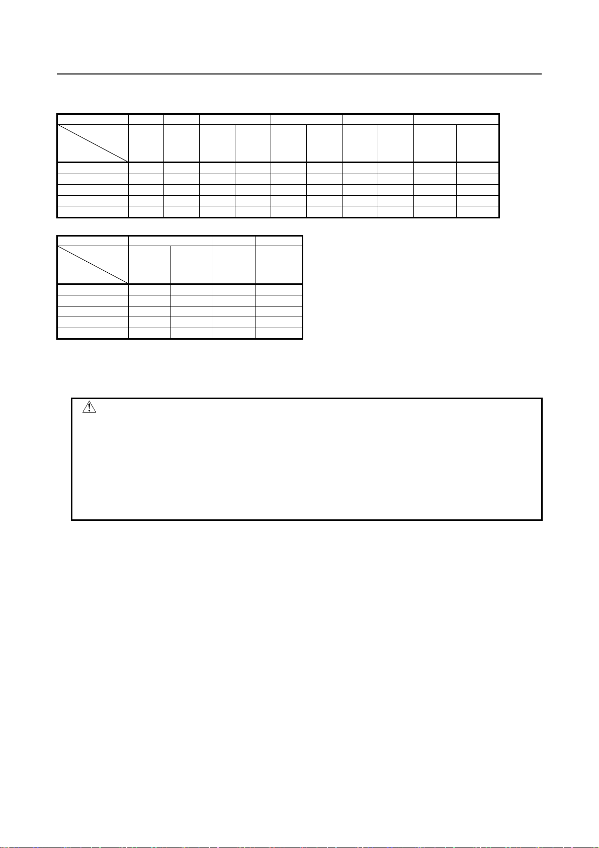
MOTOR INSULATION RESISTANCE MEASUREMENT
Measure an insulation resistance between each winding and motor frame using an insulation
resistance meter (500 VDC). Judge the measurements according to the following table. Make an
insulation resistance measurement on a single motor unit after detaching cords such as a power line.
Insulation resistance Judgment
100 MΩ or higher Acceptable
10 to 100 MΩ
1 to 10 MΩ
Lower than 1 MΩ Unacceptable. Replace the motor.
The winding has begun deteriorating. There is no problem with the performance
at present. Be sure to perform periodic inspection.
The winding has considerably deteriorated. Special care is in need. Be sure to
perform periodic inspection.
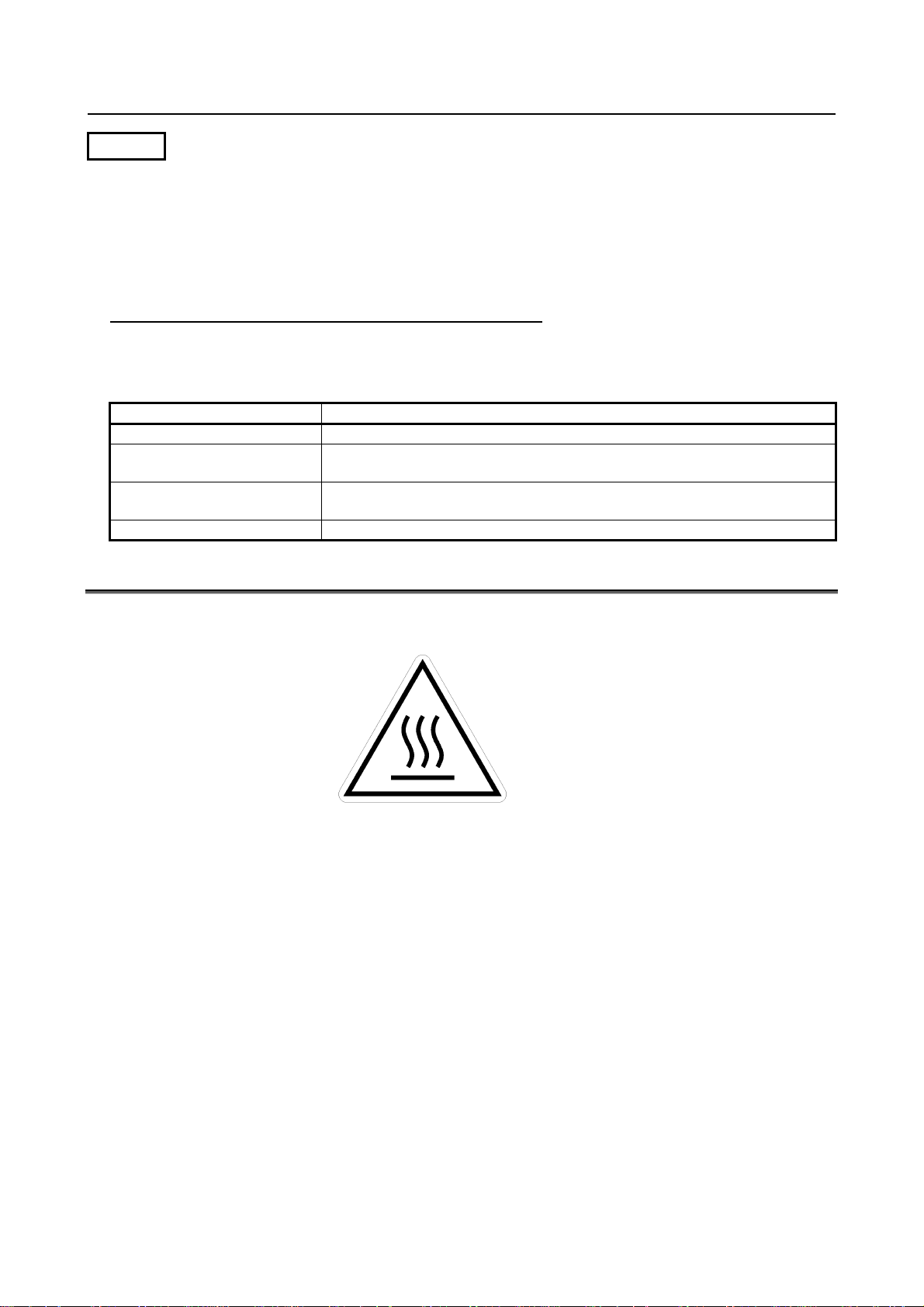
CAUTION LABEL
The following label is attached to the motor.
Attach this label to a prominent place on the motor to call attention to the user.
Heat caution label
(compliance with the IEC
standard)
Heat caution label
Since the motor is heated to a high temperature during operation or immediately after a stop, touching the
motor may cause a burn.
So, attach this label to a prominent place to call attention when the surface is exposed and may be
touched.
Remark:
The mark of this label conforms to the IEC standard, which is a global standard.
The mark has the meaning of heat caution, so the description is omitted.
s-6
Page 9

B-65262EN/06 PREFACE
PREFACE
This manual describes the specifications, outline drawings, detectors and other options, usage, and
selection method of the FANUC AC Servo Motor α
This manual describes the layout of power pins and the output of detector signals but does not provide
information about connection to a servo amplifier and an CNC. For the connection, refer to "FANUC
SERVO AMPLIFIER α
i series Descriptions (B-65282EN)", "FANUC SERVO AMPLIFIER βi series
Descriptions (B-65322EN)", and "Maintenance Manual (B-65285EN)".
In this manual, servo motor names are sometimes abbreviated as follows:
Example) α
iS 30/4000 →αiS 30
Related manuals
The following five kinds of manuals are available for FANUC SERVO MOTOR αi series. In the table,
this manual is marked with an asterisk (*).
Document name
FANUC AC SERVO MOTOR αi series
DESCRIPTIONS
FANUC SERVO AMPLIFIER αi series
DESCRIPTIONS
FANUC SERVO AMPLIFIER βi series
DESCRIPTIONS
FANUC AC SERVO MOTOR αi series
FANUC AC SPINDLE MOTOR αi
series
FANUC SERVO AMPLIFIER α
MAINTENANCE MANUAL
FANUC AC SERVO MOTOR αi series
FANUC AC SERVO MOTOR β
FANUC LINEAR MOTOR LiS series
FANUC SYNCHRONOUS BUILT-IN
SERVO MOTOR D
PARAMETER MANUAL
iS series
i series
i series
Document
number
B-65262EN
B-65282EN
B-65322EN
B-65285EN
B-65270EN
i series (αiS/αiF series).
Major contents Major usage
• Specification
• Characteristics
• External dimensions
• Specifications and
functions
• Installation
• External dimensions
and maintenance area
• Connections
• Start up procedure
• Troubleshooting
• Maintenance of motor
• Initial setting
• Setting parameters
• Description of
parameters
• Selection of motor
• Connection of motor
• Selection of amplifier
• Connection of
amplifier
• Start up the system
(Hardware)
• Troubleshooting
• Maintenance of motor
• Start up the system
(Software)
• Tuning the system
(Parameters)
*
p-1
Page 10

Page 11

B-65262EN/06 TABLE OF CONTENTS
TABLE OF CONTENTS
SAFETY PRECAUTIONS............................................................................s-1
DEFINITION OF WARNING, CAUTION, AND NOTE.............................................s-1
WARNING...............................................................................................................s-2
CAUTION................................................................................................................s-4
NOTE......................................................................................................................s-5
CAUTION LABEL....................................................................................................s-6
PREFACE....................................................................................................p-1
1 GENERAL...............................................................................................1
1.1 LINEUP OF THE SERIES .............................................................................1
1.2 FEATURE......................................................................................................2
2 ORDERING SPECIFICATION NUMBER................................................4
2.1 ORDERING SPECIFICATION NUMBER ......................................................4
2.2 APPLICABLE AMPLIFIERS...........................................................................8
3 USAGE..................................................................................................12
3.1 USE ENVIRONMENT FOR SERVO MOTORS...........................................12
3.1.1 Ambient Temperature, Humidity, Installation Height, and Vibration....................12
3.1.2 Usage Considering Environmental Resistance.......................................................13
3.1.3 Checking a Delivered Servo Motor and Storing a Servo Motor............................18
3.1.4 Separating and Disposing of a Servo Motor...........................................................19
3.2 CONNECTING A SERVO MOTOR .............................................................19
3.2.1 Connections Related to a Servo Motor...................................................................19
3.3 MOUNTING A SERVO MOTOR..................................................................21
3.3.1 Methods for coupling the shaft...............................................................................21
3.3.2 Fastening the Shaft.................................................................................................22
3.3.3 Allowable Axis Load for a Servo Motor................................................................23
3.3.4 Shaft Run-out Precision of a Servo Motor.............................................................23
3.3.5 Other Notes on Axis Design...................................................................................24
3.3.6 Cautions in Mounting a Servo Motor.....................................................................26
4 SELECTING A MOTOR ........................................................................29
4.1 CONDITIONS FOR SELECTING A SERVO MOTOR.................................29
4.2 SELECTING A MOTOR...............................................................................31
4.2.1 Calculating the Load Torque..................................................................................32
4.2.2 Calculating the Motor Speed ..................................................................................33
4.2.3 Calculating the Load Inertia...................................................................................34
4.2.4 Calculating the Acceleration Torque......................................................................36
4.2.4.1 Calculating acceleration torque ......................................................................... 36
4.2.4.2 Calculating the torque required by the motor shaft in acceleration...................39
4.2.5 Calculating the Root-mean-square Value of the Torques ......................................40
4.2.6 Calculating the Percentage Duty Cycle and ON Time with the Maximum
Cutting Torque .......................................................................................................42
4.2.7 Calculating the Dynamic Brake Stop Distance......................................................43
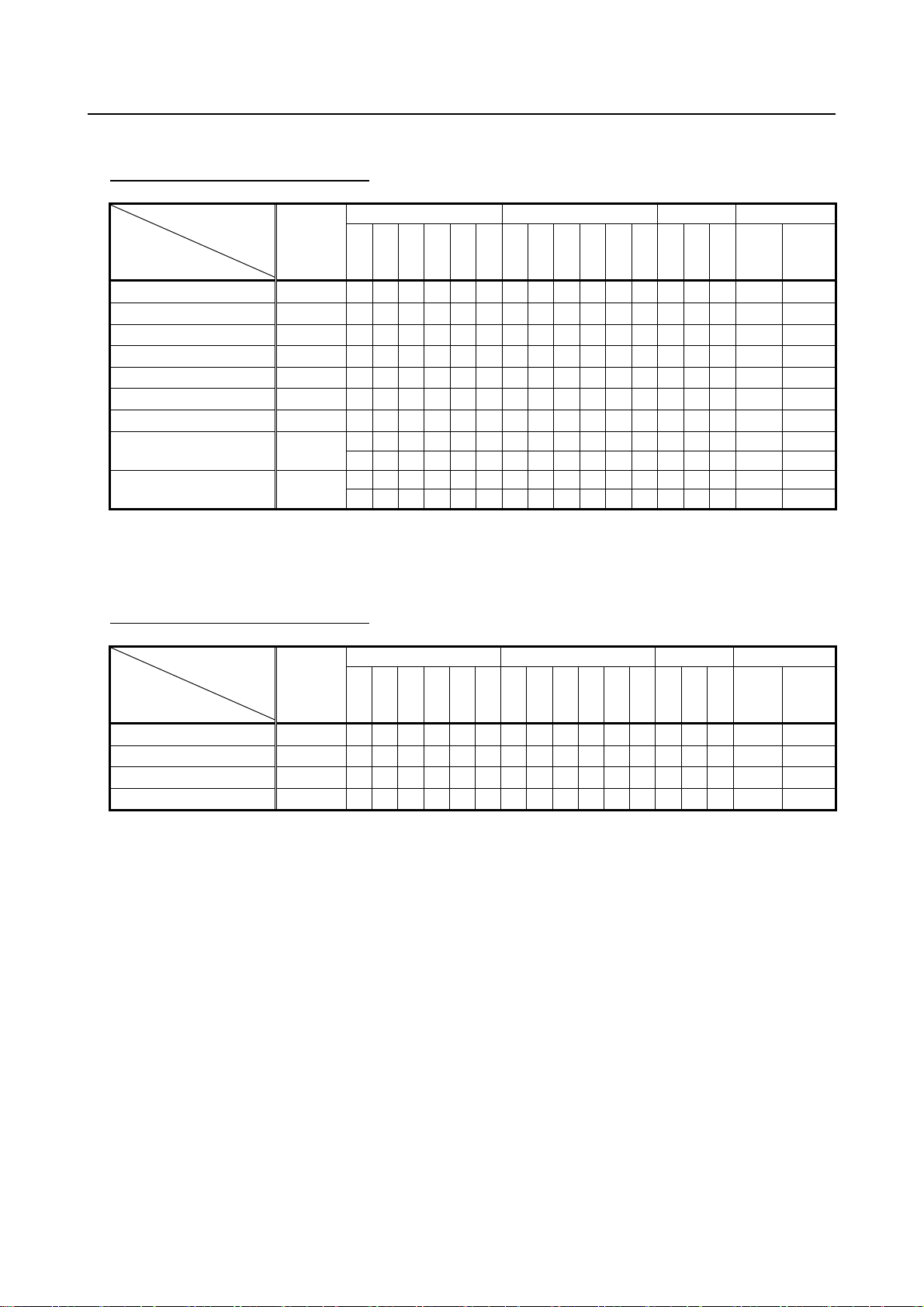
4.3 HOW TO FILL IN THE SERVO MOTOR SELECTION DATA TABLE.........47
4.3.1 Servo Motor Selection Data Table.........................................................................47
4.3.2 Explanation of Items ..............................................................................................50
c-1
Page 12

TABLE OF CONTENTS B-65262EN/06
4.3.2.1 Title.................................................................................................................... 50
4.3.2.2 Specifications of moving object ........................................................................ 50
4.3.2.3 Mechanical specifications.................................................................................. 51
4.3.2.4 Motor specifications and characteristics............................................................53
4.4 CHARACTERISTIC CURVE AND DATA SHEET........................................54
4.4.1 Characteristic Curves..............................................................................................54
4.4.2 Data Sheet...............................................................................................................57
5 CONDITIONS FOR APPROVAL RELATED TO THE IEC60034
STANDARD...........................................................................................59
5.1 TYPES OF MOTORS TO BE APPROVED..................................................59
5.2 APPROVED SPECIFICATIONS..................................................................61
5.2.1 Motor Speed (IEC60034-1)....................................................................................61
5.2.2 Output (IEC60034-1) .............................................................................................61
5.2.3 Protection Type (IEC60034-5)...............................................................................61
5.2.4 Cooling Method (IEC60034-6)..............................................................................62
5.2.5 Mounting Method (IEC60034-7)...........................................................................62
5.2.6 Grounding (IEC60204-1).......................................................................................63
5.2.7 Remarks..................................................................................................................63
5.3 CONNECTORS REQUIRED FOR APPROVAL...........................................63
6 SPECIFICATIONS.................................................................................64
6.1 αiS series (200V).........................................................................................66
6.2 αiS series (400V).........................................................................................88
6.3 αiF series (200V).......................................................................................116
6.4 αiF series (400V).......................................................................................125
7 OUTLINE DRAWINGS........................................................................129
7.1 MODELS αiS 2 to αiS 4, αiS 2HV to αiS 4HV, AND αiF 1 to αiF 2..........130
7.1.1 Outline Drawing of the Motors............................................................................130
7.1.2 Shaft Shape...........................................................................................................132
7.1.3 Allowable Axis Load............................................................................................134
7.1.4 Shaft Run-out Precision........................................................................................134
7.1.5 Power and Brake Connector.................................................................................134
7.2 MODELS αiS 8 to αiS 12, αiS 8HV to αiS 12HV, αiF 4 to αiF 8,
αiF 4HV to αiF 8HV...................................................................................135
7.2.1 Outline Drawing of the Motors............................................................................135
7.2.2 Shaft Shape...........................................................................................................136
7.2.3 Allowable Axis Load............................................................................................140
7.2.4 Shaft Run-out Precision........................................................................................140
7.2.5 Power Connector..................................................................................................141
7.3 MODELS αiS 22 to αiS 60 with FAN,αiS 22HV to αiS 60HV with FAN,
αiF 12 to αiF 40 with FAN, αiF 12HV to αiF 22HV....................................142
7.3.1 Outline Drawing of the Motors............................................................................142
7.3.2 Shaft Shape...........................................................................................................146
7.3.3 Allowable Axis Load............................................................................................147
7.3.4 Shaft Run-out Precision........................................................................................148
7.3.5 Connector .............................................................................................................148
7.4 MODELS αiS 100 to αiS 200 with FAN,
αiS 100HV to αiS 200HV with FAN...........................................................150
7.4.1 Outline Drawing of the Motors............................................................................150
7.4.2 Allowable Axis Load............................................................................................153
c-2
Page 13

B-65262EN/06 TABLE OF CONTENTS
7.4.3 Shaft Run-out Precision........................................................................................153
7.4.4 Power Terminal Layout........................................................................................154
7.4.5 Cabling .................................................................................................................155
7.5 MODELS αiS 300, αiS 500, αiS 300 HV, AND αiS 500 HV......................156
7.5.1 Outline Drawing of the Motors............................................................................156
7.5.2 Allowable Axis Load............................................................................................156
7.5.3 Shaft Run-out Precision........................................................................................156
7.5.4 Power Terminal Layout (for αiS 300 and αiS 500).............................................157
7.5.5 Power Terminal Layout (for αiS 300HV and αiS 500HV)..................................157
7.5.6 Cabling (for αiS 300, αiS 500, αiS 300HV, and αiS 500HV) ............................158
7.6 MODEL αiS 1000/2000 HV (A06B-0098-B010).........................................159
7.6.1 Outline Drawing of the Motors............................................................................159
7.6.2 Allowable Axis Load............................................................................................159
7.6.3 Shaft Run-out Precision........................................................................................160
7.6.4 Power Terminal Layout........................................................................................160
7.6.5 Cabling .................................................................................................................161
7.7 MODEL αiS 1000/3000 HV (A06B-0099-B010).........................................162
7.7.1 Outline Drawing of the Motors............................................................................162
7.7.2 Allowable Axis Load............................................................................................162
7.7.3 Shaft Run-out Precision........................................................................................163
7.7.4 Power Terminal Layout........................................................................................163
7.7.5 Cabling .................................................................................................................164
7.8 MODELS αiS 2000 HV AND αiS 3000 HV................................................165
7.8.1 Outline Drawing of the Motors............................................................................165
7.8.2 Allowable Axis Load............................................................................................166
7.8.3 Shaft Run-out Precision........................................................................................166
7.8.4 Power Terminal Layout........................................................................................166
7.8.5 Cabling .................................................................................................................167
8 FEEDBACK SENSOR.........................................................................168
8.1 PULSECODER..........................................................................................168
8.1.1 Types of Pulsecoders and Designation.................................................................168
8.1.2 Connecting Pulsecoder.........................................................................................168
8.1.3 Absolute-type Pulsecoder.....................................................................................169
8.2 SEPARATE PULSECODER......................................................................169
8.2.1 Separate Pulsecoder Type and Designation .........................................................169
8.2.2 Separate Pulsecoder Specifications......................................................................170
8.2.3 Connecting a Separate Type Pulsecoder..............................................................170
8.2.4 Outline Drawings of Separate Pulsecoder............................................................171
8.2.5 Cautions when Using a Separate Type Pulsecoder ..............................................172
9 BUILT-IN BRAKE................................................................................173
9.1 BRAKE SPECIFICATIONS........................................................................173
9.2 CONNECTING A BRAKE..........................................................................174
9.2.1 Brake Connectors.................................................................................................174
9.2.2 Connection of the Brakes.....................................................................................175
9.2.3 Parts for Brake Circuits........................................................................................176
9.3 CAUTIONS ON USE .................................................................................177
9.4 REDUCING THE AMOUNT OF BRAKE AXIS FALL.................................178
10 COOLING FAN....................................................................................179
10.1 COOLING FAN SPECIFICATIONS...........................................................179
c-3
Page 14

TABLE OF CONTENTS B-65262EN/06
10.2 CONNECTING A COOLING FAN..............................................................180
10.3 COOLING FAN CIRCUIT ..........................................................................181
10.4 RECOMMENDED PARTS OF COOLING FAN CIRCUIT..........................183
10.5 COOLING FAN PROTECTION CIRCUIT..................................................184
11 CONNECTORS ON THE CABLE SIDE..............................................185
11.1 CONNECTORS FOR SIGNALS (FOR ALL αi SERIES MODELS)............186
11.2 CONNECTORS FOR POWER..................................................................191
11.2.1 Connectors for Power (for Group A)....................................................................191
11.2.2 Connectors for Power (for Groups B to D)..........................................................192
11.3 CONNECTORS FOR THE BRAKE ...........................................................196
11.3.1 Connectors for the Brake (for Groups B to E) .....................................................196
11.4 CONNECTORS FOR THE FAN ................................................................197
11.5 CONNECTION TO A CONDUIT HOSE.....................................................199
c-4
Page 15

B-65262EN/06 1.GENERAL
1 GENERAL
Chapter 1, "GENERAL", consists of the following sections:
1.1 LINEUP OF THE SERIES ...................................................................................................................1
1.2 FEATURE.............................................................................................................................................2
1.1 LINEUP OF THE SERIES
The FANUC AC Servo Motor αi series consist of the following series, each of which has the listed
characteristics.
Series Voltage Stall torque Feature Applications
αiS
αiF
Lineup
Stall torque
Nm
Flange size
mm
αiS
Stall torque
Nm
200V 2 to 500 N⋅m
400V 2 to 3000 N⋅m
High acceleration models for high-acceleration
machine
α
iS models applicable to 400VAC input
200V 1 to 53 N⋅m Medium Inertia models for Axis feed of machine tools
α
400V 4 to 22 N⋅m
iF models applicable to 400VAC input
2 4 8 12 22 30 40 50 60 100 200 300 500 1000 2000 3000
90 130 174 265 380 500
αiS 2
αiS 4
αiS 8
αiS 12
αiS 22
αiS 30
αiS 40
αiS 50
αiS 60
αiS 100
αiS 200
/5000
/5000
/4000
/4000
/4000
/4000
/4000
/2000
/2000
/2500
αiS 300
/2500
200V
αiS 50
αiS 60
αiS 100
/2500
FAN
αiS 100
/2500
HV
αiS 100
/2500
HV FAN
αiS 200
/2500
FAN
αiS 200
/2500
HV
αiS 200
/2500
HV FAN
αiS 300
αiS 300
400V
S 2
αi
/6000
αiS 2
/5000
HV
S 2
αi
/6000
HV
αiS 4
/6000
αiS 4
/5000
HV
αiS 4
/6000
HV
αiS 8
/6000
αiS 8
/4000
HV
αiS 8
/6000
HV
αiS 12
/6000
αiS 12
/4000
HV
αiS 12
/6000
HV
αiS 22
/6000
αiS 22
/4000
HV
αiS 22
/6000
HV
αiS 30
αiS 40
/4000
/4000
HV
HV
/3000
FAN
αiS 50
/2000
HV
αiS 50
/3000
HV FAN
/3000
FAN
αiS 60
/2000
HV
αiS 60
/3000
HV FAN
1 2 4 8 12 22 30 40
αiS 500
/2000
/2000
αiS 500
/2000
/2000
HV
HV
αiS 500
/3000
/3000
HV
HV
Lathe
Machining Center
Grinding Machine
αiS 1000
/2000 HV
αiS 1000
/3000 HV
αiS 2000
/2000 HV
αiS 3000
/2000 HV
Flange size
mm
90 130 174
αiF 40
/3000
/3000
αiF 40
/3000
FAN
αiF
200V
400V
F 1
αiF 2
αi
/5000
/5000
αiF 4
/4000
αiF 4
/4000
HV
αiF 8
/3000
αiF 8
/3000
HV
αiF 12
/3000
αiF 12
/3000
HV
αiF 22
/3000
αiF 22
/3000
HV
αiF 30
- 1 -
Page 16

1.GENERAL B-65262EN/06
1.2 FEATURE
The FANUC AC Servo Motor αi series has been designed for machine tool feed axis applications. This
servo motor α
Compact
The use of a latest magnet and the optimized mechanical design reduce the total length and weight,
therefore realizing light, compact motors.
Smooth rotation
The special magnetic pole shape which minimizes torque ripples which, when combined with precise
current control and accurate Pulsecoder feedback, enables extremely smooth motor rotation.
Excellent acceleration
The use of a special rotor shape brings small and light motors, and a high level of torque. These motors,
therefore, provide excellent acceleration characteristics.
Wide continuous-operating zone
High-density winding, low iron loss by the optimum core shape, and the use of the latest servo software
reduce heat generation during high-speed rotation to a minimum and allow a wide continuous operating
zone.
Controllability
The use of the latest servo software maintains controllability even when a disturbance occurs.
High reliability
A totally-enclosed, friction-free brushless design is used. This allows the servo motors to be used in
demanding environments with no need for special checks or maintenance.
Excellent drip-proofing
The use of waterproof connectors and FANUC's unique stator seal provide excellent drip-proofing, which
prevent ingress of liquid, such as coolant.
Built-in, high-precision encoder
A low-indexing-error optical encoder (Pulsecoder) is built into the motors. This Pulsecoder enables
precise positioning.
Pulsecoders have the resolution of 1,000,000 or 16,000,000 per revolution. As such, the motors can be
used for positioning applications ranging from simple positioning to those requiring a high degree of
precision.
Powerful brake
A powerful brake with an increased holding torque is available as an option. The brake uses an
asbestos-free design.
200-V and 400-V power supply specifications
A lineup of 400-V power supply specification motors is provided in addition to the 200-V power supply
specification motors.
A suitable motor can be selected according to the local power supply specification.
i series has the following features:
- 2 -
Page 17
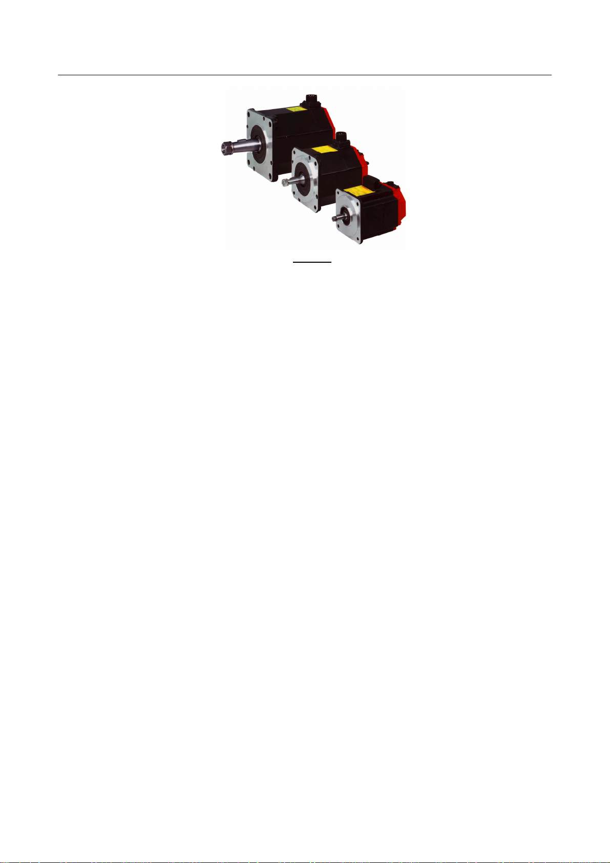
B-65262EN/06 1.GENERAL
αi series
- 3 -
Page 18

2.ORDERING SPECIFICATION NUMBER B-65262EN/06
2 ORDERING SPECIFICATION NUMBER
This chapter provides information about the ordering specification numbers and types of the FANUC AC
Servo Motor α
Chapter 2, "ORDERING SPECIFICATION NUMBER", consists of the following sections:
2.1 ORDERING SPECIFICATION NUMBER..........................................................................................4
2.2 APPLICABLE AMPLIFIERS ..............................................................................................................8
2.1 ORDERING SPECIFICATION NUMBER
The ordering specification numbers of the servo motors have the following format:
A06B-□□□□-B△○▽#◎◎◎◎
□□□□
An ordering specification number are described on the tables after next page.
* Every combination doesn’t exist.
△
0 : Taper shaft
1 : Straight shaft
2 : Straight shaft with a key groove
3 : Taper shaft with a 24VDC brake
4 : Straight shaft with a 24VDC brake
5 : Straight shaft with a key way and a 24VDC brake
* Do not select "Straight shaft with a key groove" when a large torque or abrupt acceleration rate
○
0 : Standard
1 : With a fan
2 : With a high-torque brake
3 : With a high-torque brake and a fan
4 : With a strong fan
5 : With a fan
* When "With a high-torque brake" is selected (○
▽
0 : Pulsecoder α
1 : Pulsecoder α
2 : Pulsecoder α
◎◎◎◎
0000 : Standard
0100 : IP67 specification
i series.
is required.
= 2 or 3), specify△ = 3 to 5.
iA 1000
iI 1000
iA 16000
- 4 -
Page 19

B-65262EN/06 2.ORDERING SPECIFICATION NUMBER
* Omitted in case of #0000.
The following table lists the allowable combinations of numbers represented by symbols in ordering
specification numbers.
αiS series (200V)
A06B-□□□□-B△○▽#◎◎◎◎
Symbol in
specification
Servo motor name
αiS 2/5000
αiS 2/6000
αiS 4/5000
αiS 4/6000
αiS 8/4000
αiS 8/6000
αiS 12/4000
αiS 12/6000
αiS 22/4000
αiS 22/6000
αiS 30/4000
αiS 40/4000
αiS 50/2000
αiS 60/2000
αiS 50/3000 with fan
αiS 60/3000 with fan
αiS 100/2500
αiS 100/2500 with fan
αiS 200/2500
αiS 200/2500 with fan
αiS 300/2000
αiS 500/2000
No.
□□□□
0212
0218
0215
0210
0235
0232
0238
0230
0265
0262
0268
0272
0042
0044
0275
0278
0285
0285
0288
0288
0292
0295
0 123450123450 1 2 0000 0100
○ ○ ○ ○ ○ ○ ○ - - - - - ○ ○ ○ ○ ○
○ ○ ○ ○ ○ ○ ○ - - - - - ○ ○ ○ ○ ○
○ ○ ○ ○ ○ ○ ○ - - - - - ○ ○ ○ ○ ○
○ ○ ○ ○ ○ ○ ○ - - - - - ○ ○ ○ ○ ○
○ ○ ○ ○ ○ ○ ○ - - - - - ○ ○ ○ ○ ○
○ ○ ○ ○ ○ ○ ○ - - - - - ○ ○ ○ ○ ○
○ ○ ○ ○ ○ ○ ○ - - - - - ○ ○ ○ ○ ○
○ ○ ○ ○ ○ ○ ○ - - - - - ○ ○ ○ ○ ○
○ ○ ○ ○ ○ ○ ○ - - - - - ○ ○ ○ ○ ○
○ ○ ○ ○ ○ ○ ○ - - - - - ○ ○ ○ ○ ○
○ ○ ○ ○ ○ ○ ○ - - - - - ○ ○ ○ ○ ○
○ ○ ○ ○ ○ ○ ○ - - - - - ○ ○ ○ ○ ○
- - - ○ ○ ○ - - ○ - - - ○ ○ ○ ○ ○
○ ○ - - - - ○ - - - - - ○ ○ ○ ○ ○
- - - ○ ○ - - - ○ - - - ○ ○ ○ ○ ○
○ ○ - - - - ○ - - - - - ○ ○ ○ ○ ○
- - - ○ ○ - - - ○ - - - ○ ○ ○ ○ ○
○ ○ - ○ ○ - - ○ - - - - ○ ○ ○ ○ -
- - - ○ ○ - - - - ○ - - ○ ○ ○ ○ -
○ ○ - - - - - ○ - - - - ○ ○ ○ ○ -
- - - ○ ○ - - - - ○ - - ○ ○ ○ ○ -
○ - - ○ - - ○ - - - - - ○ - - ○ ○
○ - - ○ - - - ○ - - - - ○ - - ○ -
○ - - ○ - - ○ - - - - - ○ - - ○ ○
○ - - ○ - - - ○ - - - - ○ - - ○ -
○ - - - - - - ○ - - - - ○ - - ○ -
○ - - - - - - ○ - - - - ○ - - ○ -
* When ◎◎◎◎ is #0000, omit the specification of ◎◎◎◎.
* Specify △ = 3 to 5 in the case of ○ = 2 or 3.
△ ○ ▽ ◎◎◎◎
- 5 -
Page 20

2.ORDERING SPECIFICATION NUMBER B-65262EN/06
αiS series (400V)
A06B-□□□□-B△○▽#◎◎◎◎
Symbol in
specification
No.
Servo motor name
αiS 2/5000 HV
αiS 2/6000 HV
αiS 4/5000 HV
αiS 4/6000 HV
αiS 8/4000 HV
αiS 8/6000 HV
αiS 12/4000 HV
αiS 12/6000 HV
αiS 22/4000 HV
αiS 22/6000 HV
αiS 30/4000 HV
αiS 40/4000 HV
αiS 50/2000 HV
αiS 60/2000 HV
αiS 50/3000 HV with fan
αiS 60/3000 HV with fan
αiS 100/2500 HV
αiS 100/2500 HV with fan
αiS 200/2500 HV
αiS 200/2500 HV with fan
αiS 300/2000 HV
αiS 300/3000 HV
αiS 500/2000 HV
αiS 500/3000 HV
αiS 1000/2000 HV
αiS 1000/3000 HV
αiS 2000/2000 HV
αiS 3000/2000 HV
□□□□
0213
0219
0216
0214
0236
0233
0239
0237
0266
0263
0269
0273
0043
0045
0276
0279
0286
0286
0289
0289
0293
0290
0296
0297
0098
0099
0091
0092
012345012345 0 1 2 0000 0100
○ ○ ○ ○ ○ ○ ○ - - - - - ○ ○ ○ ○ ○
○ ○ ○ ○ ○ ○ ○ - - - - - ○ ○ ○ ○ ○
○ ○ ○ ○ ○ ○ ○ - - - - - ○ ○ ○ ○ ○
○ ○ ○ ○ ○ ○ ○ - - - - - ○ ○ ○ ○ ○
○ ○ ○ ○ ○ ○ ○ - - - - - ○ ○ ○ ○ ○
○ ○ ○ ○ ○ ○ ○ - - - - - ○ ○ ○ ○ ○
○ ○ ○ ○ ○ ○ ○ - - - - - ○ ○ ○ ○ ○
○ ○ ○ ○ ○ ○ ○ - - - - - ○ ○ ○ ○ ○
○ ○ ○ ○ ○ ○ ○ - - - - - ○ ○ ○ ○ ○
○ ○ ○ ○ ○ ○ ○ - - - - - ○ ○ ○ ○ ○
○ ○ ○ ○ ○ ○ ○ - - - - - ○ ○ ○ ○ ○
○ ○ ○ ○ ○ ○ ○ - - - - - ○ ○ ○ ○ ○
- - - ○ ○ ○ - - ○ - - - ○ ○ ○ ○ ○
○ ○ - - - - ○ - - - - - ○ ○ ○ ○ ○
- - - ○ ○ - - - ○ - - - ○ ○ ○ ○ ○
○ ○ - - - - ○ - - - - - ○ ○ ○ ○ ○
- - - ○ ○ - - - ○ - - - ○ ○ ○ ○ ○
○ ○ - ○ ○ - - ○ - - - - ○ ○ ○ ○ -
- - - ○ ○ - - - - ○ - - ○ ○ ○ ○ -
○ ○ - - - - - ○ - - - - ○ ○ ○ ○ -
- - - ○ ○ - - - - ○ - - ○ ○ ○ ○ -
○ - - ○ - - ○ - - - - - ○ - - ○ ○
○ - - ○ - - - ○ - - - - ○ - - ○ -
○ - - ○ - - ○ - - - - - ○ - - ○ ○
○ - - ○ - - - ○ - - - - ○ - - ○ -
○ - - - - - - ○ - - - - ○ - - ○ -
○ - - - - - - ○ - - - - ○ - - ○ -
○ - - - - - - ○ - - - - ○ - - ○ -
○ - - - - - - ○ - - - - ○ - - ○ -
○ - - - - - - ○ - - - - ○ - - ○ -
○ - - - - - - - - - - ○ ○ - - ○ -
○ - - - - - - - - - ○ - ○ - - ○ -
○ - - - - - - - - - ○ - ○ - - ○ -
△ ○ ▽ ◎◎◎◎
* When ◎◎◎◎ is #0000, omit the specification of ◎◎◎◎.
* Specify △ = 3 to 5 in the case of ○ = 2 or 3.
- 6 -
Page 21
B-65262EN/06 2.ORDERING SPECIFICATION NUMBER
αiF series (200V)
A06B-□□□□-B△○▽#◎◎◎◎
Symbol in
specification
Servo motor name
αiF 1/5000
αiF 2/5000
αiF 4/4000
αiF 8/3000
αiF 12/3000
αiF 22/3000
αiF 30/3000
αiF 40/3000
αiF 40/3000 with fan
No.
□□□□
0202
0205
0223
0227
0243
0247
0253
0257
0257
△ ○ ▽
0 1 2 3 4 5 0 1 2 3 4 5 0 1 2 0000 0100
○ ○ ○ ○ ○ ○ ○ - - - - - ○ ○ ○ ○ ○
○ ○ ○ ○ ○ ○ ○ - - - - - ○ ○ ○ ○ ○
○ ○ ○ ○ ○ ○ ○ - - - - - ○ ○ ○ ○ ○
○ ○ ○ ○ ○ ○ ○ - - - - - ○ ○ ○ ○ ○
○ ○ ○ ○ ○ ○ ○ - - - - - ○ ○ ○ ○ ○
○ ○ ○ ○ ○ ○ ○ - - - - - ○ ○ ○ ○ ○
○ ○ ○ ○ ○ ○ ○ - - - - - ○ ○ ○ ○ ○
○ ○ ○ ○ ○ ○ ○ - - - - - ○ ○ ○ ○ ○
- - - ○ ○ ○ - - ○ - - - ○ ○ ○ ○ ○
○ ○ ○ ○ ○ ○ - ○ - - - - ○ ○ ○ ○ -
- - - ○ ○ ○ - - - ○ - - ○ ○ ○ ○ -
◎◎◎◎
* When ◎◎◎◎ is #0000, omit the specification of ◎◎◎◎.
* Specify △ = 3 to 5 in the case of ○ = 2 or 3.
αiF series (400V)
A06B-□□□□-B△○▽#◎◎◎◎
Symbol in
specification
Servo motor name
αiF 4/4000 HV
αiF 8/3000 HV
αiF 12/3000 HV
αiF 22/3000 HV
No.
□□□□
0225
0229
0245
0249
0 1 2 3 4 5 0 1 2 3 4 5 0 1 2 0000 0100
○ ○ ○ ○ ○ ○ ○ - - - - - ○ ○ ○ ○ ○
○ ○ ○ ○ ○ ○ ○ - - - - - ○ ○ ○ ○ ○
○ ○ ○ ○ ○ ○ ○ - - - - - ○ ○ ○ ○ ○
○ ○ ○ ○ ○ ○ ○ - - - - - ○ ○ ○ ○ ○
* When ◎◎◎◎ is #0000, omit the specification of ◎◎◎◎.
△ ○ ▽ ◎◎◎◎
- 7 -
Page 22
2.ORDERING SPECIFICATION NUMBER B-65262EN/06
2.2 APPLICABLE AMPLIFIERS
The FANUC AC Servo Motor αi series can be driven using FANUC Servo Amplifier αiSV series or
iSV series.
β
For the ordering specification numbers of servo amplifiers, refer to "FANUC SERVO AMPLIFIER α
series Descriptions (B-65282EN)" or "FANUC SERVO AMPLIFIER β
(B-65322EN)".
Combinations of αiS/αiF servo motors and αiSV/βiSV servo amplifiers
(200 V, 160 A or less)
Stall torque 1 2 4 8 12
Amplifier
αiSV 20
αiSV 20L
αiSV 40
αiSV 40L
αiSV 80
αiSV 80L
αiSV 160
αiSV 160L
αiSV 4/20
αiSV 20/20
αiSV 20/20L
αiSV 20/40
αiSV 20/40L
αiSV 40/40
αiSV 40/40L
αiSV 40/80
αiSV 40/80L
αiSV 80/80
αiSV 80/80L
αiSV 80/160
αiSV 160/160
αiSV 20/20/20
αiSV 20/20/40
βiSV 20
βiSV 40
βiSV 80
βiSV 20/20
Motor
αiS
αiF
- O O O O O
- O O
- O O O
- O
L axis
M axis O O O O O
L axis O O O O O
M axis O O O O O
L axis O O O O O
M axis O O
L axis O O
M axis O O
L axis O O
M axis O O O
L axis O O O
M axis O O O
L axis O O O
M axis O
L axis O
M axis O
L axis O O O O O
M axis O O O O O
N axis O O O O O
L axis O O O O O
M axis O O O O O
N axis O O
- O O O O O
- O O
- O O O
L axis O O O O O
M axis O O O O O
αiF 1
/5000
αiS 2
/5000
αiF 2
/5000
αiS 2
αiS 4
αiS 4
/6000
/5000
/6000
αiF 4
αiF 8
/4000
/3000
αiS 8
/4000
i series Descriptions
αiS 8
αiS12
αiS12
/6000
/4000
/6000
αiF12
/3000
i
- 8 -
Page 23
B-65262EN/06 2.ORDERING SPECIFICATION NUMBER
Stall torque 22 30 40 50 60
Motor
αiS
αiS22
/4000
αiS22
/6000
αiS30
/4000
αiS40
/4000
αiS50
/2000
αiS60
/2000
Amplifier
αiSV 20
αiSV 20L
αiSV 40
αiSV 40L
αiSV 80
αiSV 80L
αiSV 160
αiSV 160L
αiSV 4/20
αiSV 20/20
αiSV 20/20L
αiSV 20/40
αiSV 20/40L
αiSV 40/40
αiSV 40/40L
αiSV 40/80
αiSV 40/80L
αiSV 80/80
αiSV 80/80L
αiSV 80/160
αiSV 160/160
αiSV 20/20/20
αiSV 20/20/40
βiSV 20
βiSV 40
βiSV 80
βiSV 20/20
αiF
L axis
M axis
L axis
M axis
L axis
M axis
L axis
M axis
L axis
M axis O
L axis O
M axis O
L axis O
M axis O O O O O O
L axis O O O O O O
M axis O O O O O O
L axis
M axis
N axis
L axis
M axis
N axis
L axis
M axis
αiF22
/3000
-
-
- O
- O O O O O O O
-
-
- O
αiF30
/3000
αiF40
/3000
αiF40
/3000
FAN
(200 V, 360 A or more)
Stall torque 50 60 100 200 300 500
Motor
Amplifier
αiSV 360
αiSV 360 x2
αiS 50
/3000
αiS 60
FAN
O O O O O O
O O
/3000
FAN
αiS 100
/2500
αiS 100
/2500
FAN
αiS 200
/2500
αiS 200
/2500
FAN
αiS 300
/2000
αiS 500
/2000
(*) For a motor driven by multiple servo amplifier, such as the αiS 300 motor, the torque tandem
control option or the PWM distribution module is required.
- 9 -
Page 24

2.ORDERING SPECIFICATION NUMBER B-65262EN/06
(400V, 80A or less)
Stall torque 2 4 8 12
Motor
αiS
αiF
Amplifier
αiSV 10HV
αiSV 10HVL
αiSV 20HV
αiSV 20HVL
αiSV 40HV
αiSV 40HVL
αiSV 80HV
αiSV 80HV
αiSV 10/10HV
αiSV 10/10HVL
αiSV 20/20HV
αiSV 20/20HVL
αiSV 20/40HV
αiSV 20/40HVL
αiSV 40/40HV
αiSV 40/40HVL
αiSV 40/80HV
αiSV 80/80HV
βiSV 10HV
βiSV 20HV
βiSV 40HV
L axis O O O O
M axis O O O O
L axis O O
M axis O O
L axis O O
M axis O O O
L axis O O O
M axis O O O
L axis O O O
M axis O
L axis O
M axis O
Stall torque 22 30 40 50 60
Motor
Amplifier
αiSV 10HV
αiSV 10HVL
αiSV 20HV
αiSV 20HVL
αiSV 40HV
αiSV 40HVL
αiSV 80HV
αiSV 80HV
αiSV 10/10HV
αiSV 10/10HVL
αiSV 20/20HV
αiSV 20/20HVL
αiSV 20/40HV
αiSV 20/40HVL
αiSV 40/40HV
αiSV 40/40HVL
αiSV 40/80HV
αiSV 80/80HV
βiSV 10HV
βiSV 20HV
βiSV 40HV
αiS
αiF
L axis
M axis
L axis
M axis
L axis
M axis O
L axis O
M axis O
L axis O
M axis O O O O O O
L axis O O O O O O
M axis O O O O O O
αiS 2
- O O O O
- O O
- O O O
- O
- O O O O
- O O
- O O O
αiF22
-
-
- O
- O O O O O O
-
-
- O
αiS 2
/5000
HV
αiS22
/3000
HV
αiS 4
/6000
/5000
HV
αiS22
/4000
HV
HV
/6000
HV
αiS 4
/6000
HV
αiS30
/4000
HV
αiF 4
αiS40
/4000
HV
/4000
HV
αiF 8
/3000
HV
αiS50
/2000
HV
αiS 8
/4000
HV
αiS60
/2000
HV
αiS 8
/6000
HV
αiS12
/4000
HV
αiF12
/3000
HV
αiS12
/6000
HV
- 10 -
Page 25
B-65262EN/06 2.ORDERING SPECIFICATION NUMBER
(400V, 180A or more)
tall torque 50 60 100 200 300 500
Motor
Amplifier
αiSV 180HV
αiSV 360HV
αiSV 360HV x2
αiSV 360HV x4
αiSV 540HV
αiS 50
/3000
HV FAN
αiS 60
HV FAN
O O O O O O
O O
O O
/3000
αiS 100
/2500
HV
αiS 100
/2500
HV FAN
αiS 200
/2500
HV
αiS 200
/2500
HV FAN
αiS 300
/2000
HV
αiS 300
/3000
HV
αiS 500
/2000
HV
αiS 500
/3000
HV
tall torque 1000 2000 3000
Motor
Amplifier
αiSV 180HV
αiSV 360HV
αiSV 360HV x2
αiSV 360HV x4
αiSV 540HV
αiS 1000
/2000
αiS 1000
/3000
HV
O
O O O
HV
αiS 2000
/2000
HV
αiS 3000
/2000
HV
(*) For a motor driven by multiple servo amplifier, such as the αiS 1000HV motor, the torque tandem
control option or the PWM distribution module is required.
CAUTION
1 If a motor is used in a combination other than those listed above, it may become
broken.
2 For details on the servo amplifier, refer to "FANUC SERVO AMPLIFIER
series DESCRIPTIONS (B-65282EN)" and “FANUC SERVO AMPLIFIER
series DESCRIPTIONS (B-65322EN)”.
3 If you want to use a motor in combination with the α/β series servo amplifier,
consult with FANUC.
i
α
i
β
- 11 -
Page 26
3.USAGE B-65262EN/06
3 USAGE
This chapter explains how to connect the FANUC AC Servo Motor αi series to the CNC system and how
to install it in the machine.
Chapter 3, "USAGE", consists of the following sections:
3.1 USE ENVIRONMENT FOR SERVO MOTORS...............................................................................12
3.2 CONNECTING A SERVO MOTOR .................................................................................................19
3.3 MOUNTING A SERVO MOTOR......................................................................................................21
3.1 USE ENVIRONMENT FOR SERVO MOTORS
3.1.1 Ambient Temperature, Humidity, Installation Height, and
Vibration
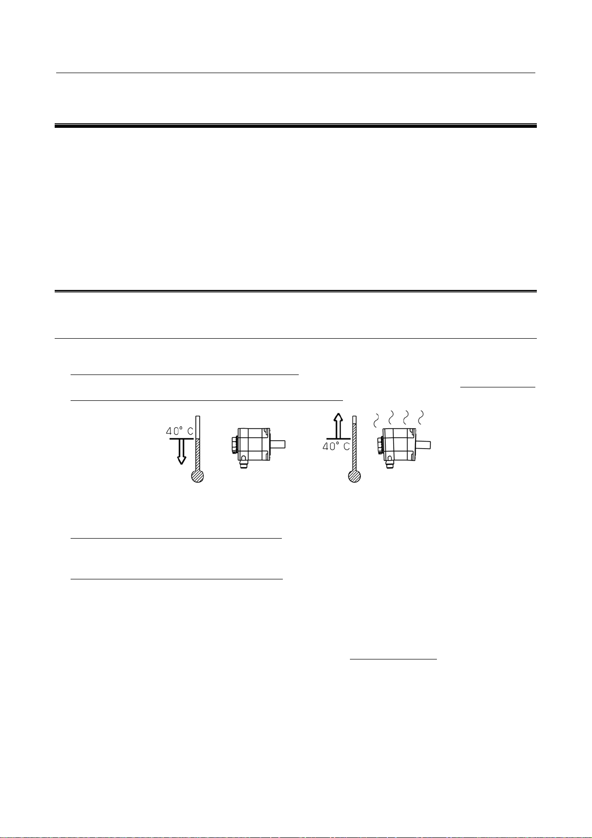
Ambient temperature
The ambient temperature should be 0°C to 40°C. If the ambient temperature exceeds this range, the
operating conditions must be eased to prevent the motor and detector from overheating. (The values in the
data sheet are determined for an ambient temperature of 20°C.)
Ambient humidity
The ambient humidity should be 80%RH or less and no condensation should not be caused.
Installation height
Up to 1,000 meters above the sea level requires, no particular provision for attitude. When operating the
machine at a higher level, special care is unnecessary if the ambient temperature is lowered 1°C at every
100m higher than 1,000m. For example, when the machine is installed at a place of 1,500 meters above
sea level, there is no problem if the ambient temperature is 35°C or less.
Vibration
When installed in a machine, the vibration applied to the motor must not exceed 5G.
If any one of the four environmental conditions (ambient temperature, ambient humidity, installation
height, and vibration) specified above is not satisfied, the output must be restricted.
- 12 -
Page 27

B-65262EN/06 3.USAGE
3.1.2 Usage Considering Environmental Resistance
Overview
The motor is an electric part, and if the lubricant or cutting fluid falls on the motor, it will enter the inside
of the motor, possibly adversely affecting the motor. In particular, if the cutting fluid adheres to the motor,
it will deteriorate the resin or rubber sealing members, causing a large amount of cutting fluid to enter the
inside of the motor and possibly damaging the motor. When using the motor, note the points described
below.
Level of motor protection
For the standard type, the level of motor protection is such that a single motor unit can satisfy IP65 of the
IEC 60034-5 standard, and a single motor unit of α
IEC 60034-5 standard. (Except the fan motor and the connectors of models with a fan. The connectors of
Pulsecoders are water-proof when engaged.)
As options, IP67 type motors are also available. (Except models with a fan and the α
above. The connectors of Pulsecoders are water-proof when engaged.)
For a description of the drip-proof and water-proof properties of each connector, see the section on that
connector.
IP4□ : Machine protected from introduction of solid foreign matter over 1.0 mm
Electric cables and wires with a diameter or thickness greater than 1.0 mm do not enter.
IP6□ : Fully dust-proof machine
Structure completely free from the entry of dust.
IP□4 : Machine protected form water spray
Water sprayed on the motor from any direction will have no harmful effect.
IP□5 : Machine protected from injected water
Water injected from a nozzle to the machine in any direction does not have a harmful impact on the
machine.
IP□7 : Machine protected from the effect of seeping water
If the machine is immersed in water at a prescribed pressure for a prescribed duration, there is no
possibility that an amount of water that has a harmful impact on the machine enters the machine.
If sufficient water-proof performance is required, as in the case in which a motor is used in a cutting fluid
mist atmosphere, specify an IP67 type motor.
Note that both the standard and IP67 types satisfy the provisions for short-time water immersion, and do
not guarantee their water-proof performance in an atmosphere in which the cutting fluid is applied
directly to the motor. Before actual use, note the points described below.
Motor periphery
If the cutting fluid or lubricant falls on the motor, it will adversely affect the sealing properties of the
motor surface, entering the inside of the motor and possibly damaging the motor. Note the following
points on use.
Make sure that the motor surface is never wet with the cutting fluid or lubricant, and also make sure that
no fluid builds up around the motor. If there is a possibility of the surface being wet, a cover is required.
Be sure to mount a cover even when using an IP67 type motor.
iS 2000/2000HV and above can satisfy IP44 of the
iS 300/2000 and
- 13 -
Page 28
3.USAGE B-65262EN/06
If the cutting fluid is misted, the cutting fluid may be condensed on the inside of the cover and fall on the
motor. Make sure that no condensed droplets fall on the motor.
Completely separate the machining area from the motor area, using a telescopic cover, accordion curtain,
and so on. Note that partitions such as accordion curtains are consumable and require periodic inspection
for damage.
Output shaft seal (oil seal)
For all models, the shaft of the servo motor is provided with an oil seal to prevent entry of oil and other
fluids into the motor. It does not, however, completely prevent the entry of lubricant and other fluids
depending on the working conditions. Note the following points on use.
When the motor is rotating, the oil seal has an effect of discharging any oil that enters, but if it is
pressurized for a long time when the motor is stopped, it may allow oil to enter through the lip. When
lubrication with an oil bath is conducted for gear engagement, for example, the oil level must be below
the lip of the oil seal of the shaft, and the oil level must be adjusted so that the oil does nothing but splash
on the lip.
Diameters of the oil seal lips of motor shafts
Motor model Oil seal diameter
αiS 2, αiS 4, αiS 2 HV, αiS 4 HV,
αiF 1, αiF 2
αiS 8, αiS 12, αiS 8 HV, αiS 12 HV,
αiF 4, αiF 8, αiF 4 HV, αiF 8 HV
αiS 22, αiS 30, αiS 40,
α
iS 22 HV, αiS 30 HV, αiS 40 HV,
αiF 12, αiF 22, αiF 30, αiF 12 HV, αiF 22 HV
(Only the straight shaft type of the following)
α
iS 50, αiS 50 HV, αiS 60, αiS 60 HV, αiF 40
* Including those equipped with fans.
(Only the taper shaft type of the following)
αiS 50, αiS 50 HV, αiS 60, αiS 60 HV, αiF 40
* Including those equipped with fans.
αiS 100, αiS 200, αiS 100 HV, αiS 200 HV
* Including those equipped with fans.
αiS 300, αiS 500, αiS 300 HV, αiS 500 HV
αiS 1000 HV
φ15 [mm]
φ24 [mm]
φ35 [mm]
φ38 [mm]
φ55 [mm]
φ65 [mm]
φ80 [mm]
- 14 -
Page 29
B-65262EN/06 3.USAGE
Motor model Oil seal diameter
αiS 2000 HV, αiS 3000 HV
φ120 [mm]
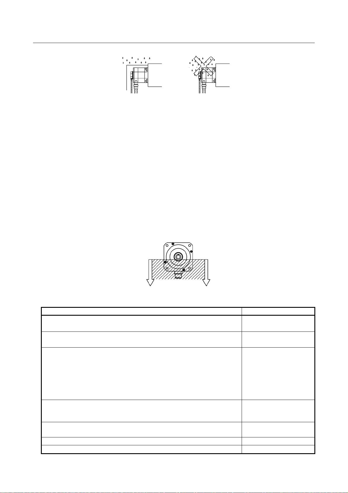
If the shaft is directed upward so that it is constantly immersed in oil, the oil seal of the motor alone does
not provide sufficient sealing. If grease is used for lubrication, the properties of the oil seal are generally
impaired. In these cases, a special design is required. For example, another oil seal is mounted on the
machine side and a drain is provided so that any oil passing through that seal can is discharged outside.
Oil, grease
Drain hole
Oil seal
In such an environment in which the lip of the oil seal switches between dry and wet states repeatedly, if
the cutting fluid flies about after the lip has worn in a dry state, the cutting fluid may easily enter the
inside of the motor. In this case, provide a cover, etc. so that no cutting fluid is applied to the oil seal of
the motor.
Ensure that no pressure is applied to the lip of the oil seal.
The cutting fluid does not provide lubrication for the oil seal lip, so that the fluid may easily enter the seal.
Provide a cover so that no cutting fluid is applied to the oil seal.
The oil seal lip is made of rubber, and if foreign matters such as cutting chips get in, it will be easily worn,
losing its sealing properties. Provide a cover, etc. to prevent cutting chips from entering near the lip.
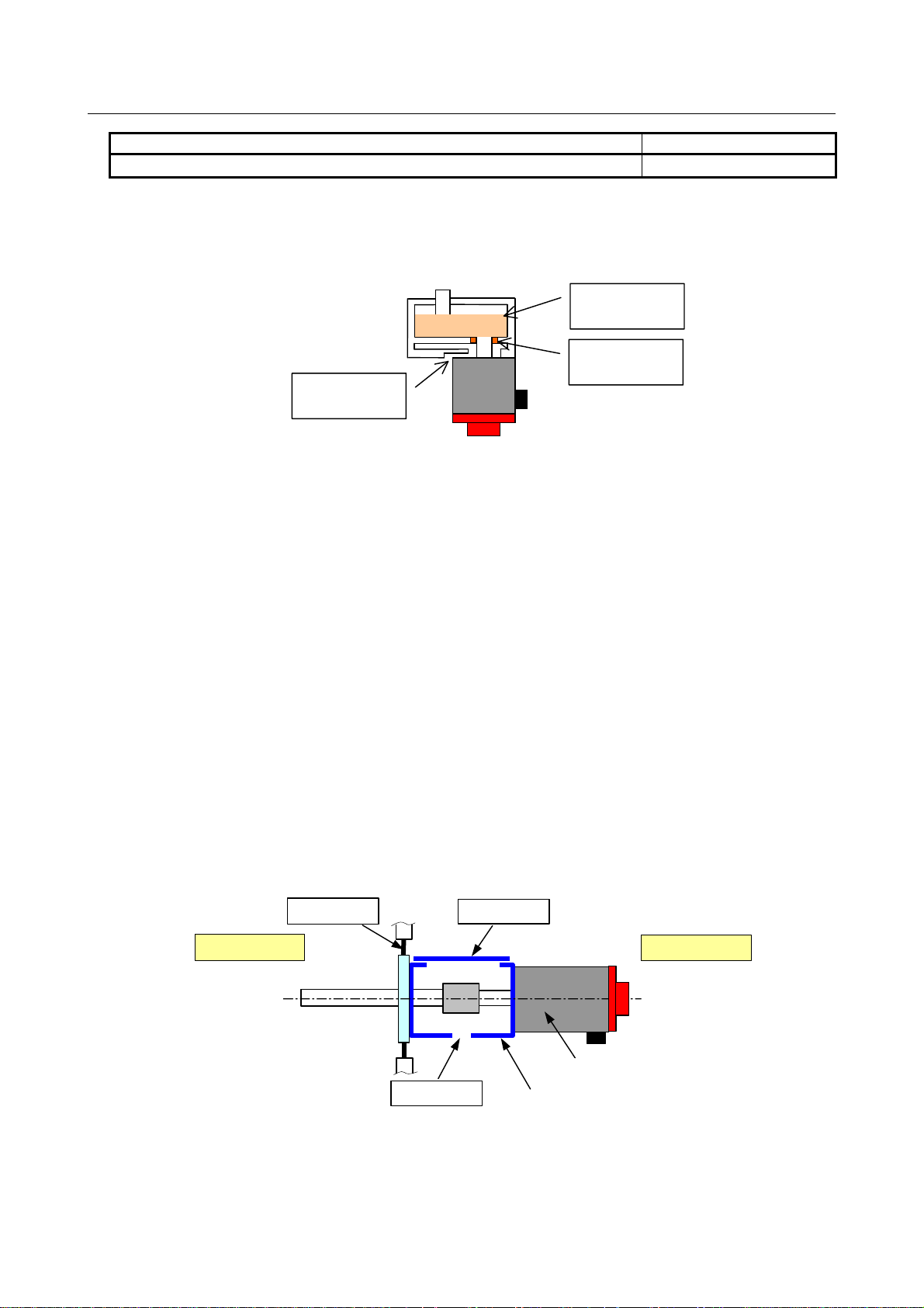
Motor coupling
If a coupling box exists between the motor and the machine, employ the structure described below so that
no cutting fluid builds up in the box.
Provide a cover for the top and sides of the coupling box.
Provide a drain hole at the bottom of the coupling box. The hole must be large enough to avoid clogging.
Make sure that any cutting fluid that bounces back is not applied from the drain hole to the motor.
Partition
Cover
Machining area
Drain
Motor
Coupling box
Motor area
<Fault example>
The cutting fluid leaks from a gap in the accordion curtain to the motor area, and builds up in the
coupling box. While the motor is moving, the cutting fluid ripples, splashing on the oil seal of the motor.
- 15 -
Page 30
3.USAGE B-65262EN/06
The cutting fluid enters the inside of the motor there in large quantities, deteriorating the insulation of the
motor.
There is a gap, so the cutting fluid
enters the motor area.
Accordion curtain
No cover, thus the cutting
fluid falls in the box.
Machining area
Drain
The hole is too small, and clogged.
Coupling box
Motor
Motor area
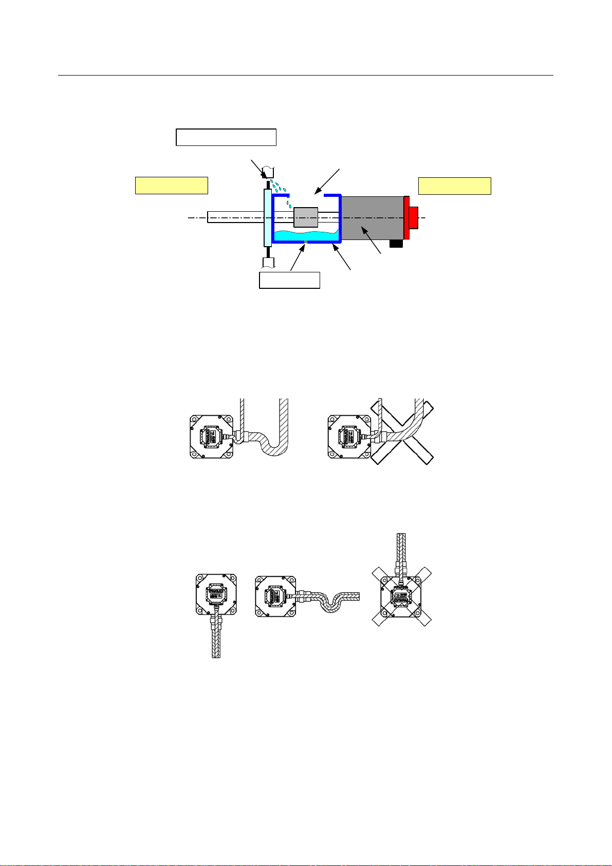
Connectors
Note the following points on use:
Make sure that no cutting fluid is introduced to the motor via cables. If the motor connector is used
horizontally, this can be accomplished by forming a slack in the cable.
If the motor connector is directed upward, the cutting fluid collects into the cable connector. Whenever
possible, direct the motor connector sideways or downward.
If there is a possibility of the power cable and the power connector being wet, it is recommended to use
the water-proof connector plug recommended in this DESCRIPTIONS for the connector and a oil-proof
cable as the power cable. (Oil-proof cable example: PUR (polyurethane) series made by LAPP)
If using a conduit hose for cable protection purposes, use the seal adapter recommended in this
DESCRIPTIONS.
- 16 -
Page 31

B-65262EN/06 3.USAGE
The feedback cable connector provides IP67 water-proof performance when it is engaged with the pulse
coder connector. If the feedback cable connector is not fully engaged, the cutting fluid will enter the
inside of the pulse coder from the connector, possibly causing a failure. Install the connector properly in
accordance with the feedback cable engagement procedure described in this DESCRIPTIONS and check
that it is engaged securely.
If the feedback cable connector cannot provide sufficient water resistance due to an assembly failure, the
cutting fluid will enter the inside of the pulse coder from the connector, possibly causing a failure. When
manufacturing a feedback cable connector, assemble it properly in accordance with the operator's manual
issued by the connector manufacturer.
Notes on cutting fluid
Cutting fluid containing highly active sulfur, oil-free cutting fluid called synthetic cutting fluid, and
highly alkaline, water-soluble cutting fluid in particular significantly affect the CNC, motor, or amplifier.
Even when these components are protected from direct spraying of cutting fluid, problems as described
below may arise. So special care should be taken.
• Cutting fluid containing highly active sulfur
Some cutting fluids containing sulfur show extremely high activity of sulfur. Ingress of such cutting
fluid into the CNC, motor, or amplifier can cause corrosion of copper, silver, and so on used as parts'
materials, therefore resulting in parts' failures.
• Synthetic cutting fluid with high permeability
Some synthetic type cutting fluids that use polyalkylene glycol (PAG) as a lubricant have extremely
high permeability. Such cutting fluid can easily penetrate into the motor even if the motor is sealed
well. Ingress of such cutting fluid into the CNC, motor, or amplifier can degrade insulation or lead to
parts' failures.
• Highly alkaline, water-soluble cutting fluid
Some cutting fluids that strengthen pH by alkanolamine show strong alkalinity of pH10 or higher
when diluted to the standard level. Ingress of such cutting fluid into the CNC, motor, or amplifier
can cause chemical reaction with plastic and so on and deteriorate them.
Terminal box
For the αiS 100/2500 model or higher, the power line is connected at the terminal box.
To ensure the appropriate IP level, a conduit or something similar is required at the power line lead-in
hole. When connecting the conduit to the terminal box, employ rubber packings, a water-proof connector,
etc. to prevent the entry of the lubricant or cutting fluid from the wiring hole in the terminal box.
- 17 -
Page 32

3.USAGE B-65262EN/06
The terminal box is provided with rubber water-proof packings. Check that the packings are not damaged,
and mount them with the prescribed tightening torque in such a way that no foreign matters get in.
NOTE
For information on the wiring hole diameters, refer to the Chapter 7, “OUTLINE
DRAWINGS.”
Fan motor
The fan motor provides low water-proof performance, so make sure that a fan unit and a fan-equipped
motor are not employed in an environment in which the cutting fluid is applied.
If lubricant or cutting fluid mist, particles, or cutting chips are drawn into the fan motor, the air holes in
the motor and the blades of the fan motor will clog, causing the cooling capacity to reduce. Employ a
machine structure that allows clean, cooling air to be fed into the motor.
Motor
Fan
Cooling air
Filter
Cooling air
3.1.3 Checking a Delivered Servo Motor and Storing a Servo Motor
When the servo motor is delivered, check the following items.
• The motor meets the specifications.
(Specifications of the model/shaft/sensor)
• Damage caused by the transportation.
• The shaft is normal when rotated by hand.
• The brake works.
- 18 -
Page 33

B-65262EN/06 3.USAGE
• Looseness or play in screws.
FANUC servo motors are completely checked before shipment, and the inspection at acceptance is
normally unnecessary. When an inspection is required, check the specifications (wiring, current, voltage,
etc.) of the motor and sensor. Store the motor indoors. The storage temperature is -20°C to +60°C. Avoid
storing in the following places.
• Place with high humidity so condensation will form.
• Place with extreme temperature changes.
• Place always exposed to vibration.
(The bearing may be damaged.)
• Place with much dust.
3.1.4 Separating and Disposing of a Servo Motor
For a servo motor, a plastic part is used.
Disassemble the motor as shown in the following figure, separate the plastic part (Pulsecoder cover), and
dispose of the motor. The following plastic material is used:
Plastic material : > (PBT+PC)-GF(30)FR(17)<
Pulse coder cover
Four hexagon head bolts M3
3.2 CONNECTING A SERVO MOTOR
3.2.1 Connections Related to a Servo Motor
For the FANUC AC Servo Motor αi series, connect the power line of the motor and the signal line of a
Pulsecoder to an FANUC Servo Amplifier. When the motor has a built-in brake or cooling fan as an
option, connect the built-in brake or cooling fan to the specified power supply.
- 19 -
Page 34

3.USAGE B-65262EN/06
A
Connection diagram
FANUC
servo Amplifier
FANUC
Servo Motor
Note
Signal line
(Pulsecoder)
Ground
line
Frame ground
Power line (motor)
Brake
Cooling fan
24VDC
power supply
C power supply
CAUTION
If a motor is not connected to ground through the machine (cabinet) in which the
motor is installed, connect the motor grounding point and the amplifier grounding
point to absorb noise. In this case, use a wire with a thickness of at least 1.25
mm2, other than the GND conductor in the power line. Keep the wire as far from
the power line as possible.
Connecting the power line
For the pin layout of the power connector on the servo motor side or the layout of the power terminals,
see Chapter 7, "OUTLINE DRAWINGS".
For details of the connector of a cable connected to the servo motor, see Chapter 11, "CONNECTORS
ON THE CABLE SIDE."
For the pin size and cabling of the models connected to the terminal block (α
100HV to α
iS 3000HV), see Chapter 7, "OUTLINE DRAWINGS".
iS 100 to αiS 500, αiS
For details of selection of a power line and the shapes of the connector and terminal connected to a servo
amplifier, refer to "FANUC SERVO AMPLIFIER α
i series Descriptions (B-65282EN)."
Connecting the signal line
For details of the signal connector on a Pulsecoder, see Chapter 8, "FEEDBACK SENSOR".
For details of the connector of a cable connected to a Pulsecoder, see Chapter 11, "CONNECTORS ON
THE CABLE SIDE."
For details of selection of a signal line and the connector connected to a servo amplifier, refer to "FANUC
SERVO AMPLIFIER α
i series Descriptions (B-65282EN)."
Connecting a built-in brake
For details of how to connect the power connector on a built-in brake and the power supply, see Chapter 9,
"BUILT-IN BRAKE."
For details of the connector of a cable connected to a built-in brake, see Chapter 11, "CONNECTORS
ON THE CABLE SIDE."
- 20 -
Page 35

B-65262EN/06 3.USAGE
Connecting a cooling fan
For the power connector on the cooling fan side, the type of power supply for driving the fan, and power
cabling, see Chapter 10, "COOLING FAN".
For details of the connector of a cable connected to a cooling fan, see Chapter 11, "CONNECTORS ON
THE CABLE SIDE."
3.3 MOUNTING A SERVO MOTOR
3.3.1 Methods for coupling the shaft
In many cases, the following four methods are used for coupling the motor shaft to the ball screw on a
machine: Direct connection through a flexible coupling, direct connection through a rigid coupling,
connection through gears, and connection through timing belts. It is important to understand the
advantages and disadvantages of each method, and select one that is most suitable for the machine.
Direct connection using a flexible coupling
Direct connection by a flexible coupling has the following advantages over connection using gears:
• Even if the angle of the motor shaft to the ball screw changes, it can be compensated to a certain
extent.
• Because a flexible coupling connects elements with less backlash, driving noise from joints can be
significantly suppressed.
However, this method has the following disadvantages:
• The motor shaft and the ball screw must not slide from each other in the radial direction (for single
coupling).
• Loose assembly may result in lower rigidity.
When the motor shaft needs to be connected directly to the ball screw, connecting them using a flexible
coupling facilitates adjustment and installation of the motor.
To use a single coupling, the machine needs to be designed so that the centers of the motor shaft and the
ball screw are aligned. (In the same way as with a rigid coupling, the use of a single coupling demands
that there be almost no relative eccentricity between the axes.)
If it is difficult to align the centers, a double coupling needs to be employed.
Flexible coupling
Ball screw
Motor shaft
Flexible coupling
Motor shaft
Locking element
Ball screw
Locking element
- 21 -
Page 36

3.USAGE B-65262EN/06
Direct connection using a rigid coupling
Direct connection using a rigid coupling has the following advantages over direct connection using a
flexible coupling:
• More economical
• The coupling rigidity can be increased.
• If the rigidity is the same as with a flexible coupling, the inertia can be reduced.
However, this method has the following disadvantages:
• The motor shaft and the ball screw must not slide from each other in the radial direction, and the
angle of the motor shaft to the ball screw must be fixed.
For this reason, a rigid coupling needs to be mounted very carefully.
It is desirable that the run-out of the ball screw is 0.01 mm or less. When a rigid coupling is used on the
motor shaft, the run-out of the hole for the ball screw must be set to 0.01 mm or less by adjusting the
tightness of the locking element.
The run-out of the motor shaft and the ball screw in the radial direction can be adjusted or compensated to
a certain extent by deflection. Note, however, that it is difficult to adjust or measure changes in the angle.
Therefore, the structure of the machine should be such that precision can be fully guaranteed.
Gears
This method is used when the motor cannot be put in line with the ball screw because of the mechanical
interference problem or when the reduction gear is required in order to obtain large torque. The following
attention should be paid to the gear coupling method:
• Grinding finish should be given to the gear, and eccentricity, pitch error, tooth-shape deviations etc.
should be reduced as much as possible. Please use the JIS, First Class as a reference of precision.
• Adjustment of backlash should be carefully performed. Generally, if there is too little backlash, a
high-pitched noise will occur during high-speed operation, and if the backlash is too big, a
drumming sound of the tooth surfaces will occur during acceleration/deceleration. Since these noises
are sensitive to the amount of backlash, the structure should be so that adjustment of backlash is
possible at construction time.
Timing belt
A timing belt is used in the same cases as gear connection, but in comparison, it has advantages such as
low cost and reduced noise during operation, etc. However, it is necessary to correctly understand the
characteristics of timing belts and use them appropriately to maintain high precision.
Generally, the rigidity of timing belt is sufficiently higher than that of
other mechanical parts such as ball screw or bearing, so there is no danger of inferiority of performance of
control caused by reduction of rigidity by using timing belt. When using a timing belt with a position
sensor on the motor shaft, there are cases where poor precision caused by backlash of the belt tooth and
pulley tooth, or elongation of belt after a long time becomes problem, so consideration should be given to
whether these errors significantly affect precision. In case the position sensor is mounted behind the
timing belt (for example, on the ball screw axis), a problem of precision does not occur.
Life of the timing belt largely varies according to mounting precision and tension adjustment. Please refer
to the manufacturer's Instruction Manual for correct use.
3.3.2 Fastening the Shaft
Taper shaft
In case of taper shafts, the load must be exerted on the tapered surface.
For this reason, at least 70% of gage fitting is required on the tapered surface.
In addition, the screw at the end of the taper shaft must be tightened with a proper torque to achieve
sufficient axial force.
- 22 -
Page 37

B-65262EN/06 3.USAGE
Straight shaft
To use a straight shaft that has no key way, connect the shaft with a coupling using a locking element.
Because the locking element connects elements by the friction generated when the screw is tightened, it is
free from backlash and the concentration of stress. For this reason, the locking element is highly reliable
for connecting elements.
To assure sufficient transmission with the locking element, factors such as the tightening torque of the
screw, the size of the screw, the number of screws, the clamping flange, and the rigidity of connecting
elements are important. Refer to the manufacturer's specifications before using the locking element. When
a coupling or gear is mounted using the locking element, tighten the screws to remove a run-out of the
coupling or gear including the shaft.
Straight shaft with a key way
In a straight shaft with a key way, torque is transmitted at the key.
This means that if there is a looseness between the key and key way, the impact incurred at the time of
inversion increases, which can result in shaft breakage, or a backlash occurs as a result of the looseness,
which can lower positioning accuracy. Therefore, the key and key way should be designed so as to
minimize the looseness between them.
When performing acceleration abruptly or frequently, select a taper shaft or straight shaft with no key
groove.
3.3.3 Allowable Axis Load for a Servo Motor
The allowable axis load for the shaft of each motor is indicated in Chapter 7, "OUTLINE DRAWINGS".
Using a motor under a load higher than the allowable axial load may break the motor. When designing a
machine and connecting a motor to the machine, fully consider the following points:
• The allowable radial load is determined, assuming that a radial load is applied to the end of the shaft.
• Applying a load higher than the allowable axis load may break the bearing. Applying a radial load
higher than the allowable radial load may break the shaft due to a fatigue failure.
• A radial load indicates the constant force continuously applied to the shaft depending on the
mounting method (such as belt tension) and the force by the load torque (such as dividing moment
by pulley radius).
• When a timing belt is used, the belt tension is critical particularly. Too tight a belt causes a fault
such as the broken shaft. Belt tension must be controlled so as not to exceed the limits calculated
from the allowable radial load. Positioning the pulley as close to the bearing as possible in design
can prevent possible faults such as the broken shaft.
• In some use conditions, the pulley diameter and gear size should be considered. For example, when
i F4 model is used with a gear and pulley with a radius of 2.5 cm or less, the radial load with a
the α
torque of 17.6 Nm (180 kgfcm) exceeds the allowable axis load, 686 N (70 kgf). In this case, take
measures such as supporting the end of the motor shaft mechanically.
• If a motor may be used under a load higher than the allowable axis load, the machine tool builder
should examine the life by referencing the shaft diameter, bearing, and other factors. Since the
standard single-row deep-groove ball bearing is used for the motor bearing, a too high axial load
cannot be used. To use a worm or helical gear, in particular, use another bearing.
• The motor bearing is generally fixed with a C-snap ring, and there is a small play in the axial
direction. If the axial play affects the positioning in the case of using a worm or helical gear, fit it
with another bearing.
3.3.4 Shaft Run-out Precision of a Servo Motor
The shaft run-out precision of each motor is indicated in Chapter 7, "OUTLINE DRAWINGS". The
methods of measuring the shaft run-out precision are specified below:
- 23 -
Page 38

3.USAGE B-65262EN/06
Item Measuring method
Within 10 mm
from the end of
the shaft
Shaft diameter run-out
Run-out of the faucet joint for mounting the
flange against the center of the shaft
(Only for flange type)
Run-out of the flange mounting surface
against the center of the shaft (Only for
flange type)
3.3.5 Other Notes on Axis Design
Machine movement per 1 revolution of motor shaft
The machine movement per 1 revolution of motor shaft must be determined at the first stage of machine
design referring the load torque, load inertia, rapid traverse speed, and relation between minimum
increment and resolution of the position sensor mounted on the motor shaft. To determine this amount,
the following conditions should be taken into consideration.
• The machine movement per 1 revolution of motor shaft must be such that the desired rapid traverse
speed can be obtained. For example, if the maximum motor speed is 1500 min
traverse speed must be 12 m/min., the machine movement per 1 rev. must be 8 mm/rev. or higher.
• As the machine movement per 1 revolution of motor shaft is reduced, both the load torque and the
load inertia reflected to motor shaft also decrease.
Therefore, to obtain large thrust, the machine movement per 1 rev. should be the lowest value at
which the desired rapid traverse speed can be obtained.
• Assuming that the accuracy of the reduction gear is ideal, it is advantageous to make the machine
movement per 1 rev. of motor shaft as low as possible to obtain the highest accuracy in mechanical
servo operations. In addition, minimizing the machine movement per 1 rev. of motor shaft can
increase the servo rigidity as seen from the machine's side, which can contribute to system accuracy
and minimize the influence of external load changes.
-1
and the rapid
- 24 -
Page 39

B-65262EN/06 3.USAGE
• When the machine is operation is characterized by repeated acceleration/deceleration cycles, a
heating problem may occur due to the current flow caused by the acceleration and deceleration.
Should this occur, the machine travel distance per motor shaft revolution should be modified. Given
optimum conditions, the machine travel distance per motor shaft revolution is set such that the
motor's rotor inertia equals the load inertia based on motor shaft conversion. For machines such as
punch presses and PCB drilling machines, the machine's travel distance per motor shaft revolution
should be set so as to satisfy this optimum condition as far as possible, while also considering the
rapid traverse rate and increment system.
Precautions for using linear scale
In the case where the machine moves in a linear direction and movement is directly detected by linear
scale such as inductosyn, magne-scale etc., special considerations are necessary in comparison with the
method where feedback is produced by detecting the motor shaft rotation. This is because the machine
movement now directly
influences the characteristics of the control system.
The following block diagram shows feedback produced using a linear scale.
Pulsecoder Linear scale
Motor
Command
Position
control
circuit
Velocity
control
circuit
The response of this control system is determined by the adjustment value (position loop gain) of the
position control circuit. In other words, the position loop gain is determined by the specified response
time of the control system. In the diagram above, the section enclosed by the broken line is called the
velocity loop.
Unless the response time of this section where position signal is detected is sufficiently shorter than the
response time determined by the position loop gain, the system does not operate properly. In other words,
when a command signal is put into point A, response time of the machine where position signals are
detected must be sufficiently shorter than the response time defined by the position loop gain.
If the response of the sensor section is slow, the position loop gain should be reduced to have the system
operate normally, and as a result, the response of the whole system becomes slow. The same problem is
caused when inertia is great.
The main causes for slow response are the mass of the machine and the elastic deformation of the
machine system. The larger the volume, and the greater the elastic deformation, the slower the response
becomes.
As an index for estimating the response of this machine system, the natural frequency of the machine is
used, and this is briefly calculated by the following equation.
K
W ×=
m
1
2
m
J
π
L
Wm : Natural frequency
: Load inertia reflected to motor shaft
J
L
: Rigidity of machine system
K
m
(=Torque necessary to elastically deform 1[rad] at the motor shaft when the machine table is
clamped.)
The above values can be obtained by calculating the elastic deformation for each section of the driving
system. The machine should be designed so that the value of this natural frequency [Hz] will be more
than or equal to the value of the position loop gain [sec
-1
]. For example, when setting 20 [sec-1] as the
value of position loop gain, natural frequency of machine system must be more than 20 [Hz].
- 25 -
Page 40

3.USAGE B-65262EN/06
In this case, the response of the control system becomes a problem for extremely small amounts of
movement. Consequently, the natural frequency should be calculated from the rigidity at extremely small
displacement such as 10 [μm] or less.
Stick slip
If machine movement causes a stick slip, the control system does not operate normally. That is, it does
not stop where it is supposed to, but a phenomenon occurs where it goes beyond and then back within an
extremely small range (hunting).
To avoid stick slip, the machine rigidity should be increased, or friction characteristics of the sliding
surface should be improved. When the sliding surface friction characteristic is as in the figure below,
stick slip occurs easily.
Friction coefficient
Proper friction
characteristic
Friction characteristic which
causes stick slip
Speed
Value of machine overrun (Damping coefficient of machine system)
When the machine is floated by static pressure, etc., there are cases where the machine keeps on moving
within the range of backlash although the motor shaft has stopped. If this amount is large, hunting will
also occur. To avoid this, backlash should be reduced (especially the backlash of the last mass where
position sensor is mounted) and the appropriate damping should be considered.
Reciprocating motion over a short distance
Continuing reciprocating motions over a short distance with a small number of revolutions causes the
bearing to become short of lubricant, which can shorten the life of the bearing. When such motions are
performed, special care should be taken by, for example, turning the motor at least one turn periodically.
3.3.6 Cautions in Mounting a Servo Motor
The servo motor contains precision sensor, and is carefully machined and assembled to provide the
required precision. Pay attention to the following items to maintain the precision and prevent damage to
the sensor.
• Secure the servo motor uniformly using four bolt holes provided on the front flange. (For the α
1000HV to α
be used as the reference for alignment to the machine.)
iS 3000HV, the motor's own weight must be supported by the feet, and the flange must
iS
• Ensure that the surface on which the machine is mounted is sufficiently flat.
When mounting on the machine, take care not to apply a shock to the motor.
- 26 -
Page 41

B-65262EN/06 3.USAGE
• When it is unavoidable to tap the motor for adjusting the position, etc., use a plastic hammer and tap
only the front flange if possible.
A precision sensor is directly connected to the servo motor shaft.
Pay attention to the following items to prevent damage to the sensor.
• When connecting the power transmission elements such as a gear, a pulley and a coupling to the
shaft, take care not to apply a shock to the shaft.
• Generally, in the case of straight shaft, use a locking element for connection with the shaft.
• In the case of tapered shaft, match the tapered surface with the power transmission element and fix
by tightening the screw at the end. When the woodruff key is too tight, don't tap it with a hammer.
Use the woodruff key mainly for positioning, and use the tapered surface for torque transmission.
Machine the tapered surface of the power transmission element so that over 70% of the whole
surface is contacted.
• To remove the connected power transmission element, be sure to use a jig such as a gear puller.
- 27 -
Page 42

3.USAGE B-65262EN/06
• When tapping slightly to remove the tightly contacted tapered surface, tap in the radial direction to
prevent a shock in the axial direction.
• Suppress the rotary unbalance of the connected power transmission element to the level as low as
possible. It is usually believed that there is no problem in the symmetrical form. Be careful when
rotating continuously the asymmetrical different form power transmission element. Even if the
vibration caused by the unbalance is as small as 0.5G, it may damage the motor bearing or the
sensor.
• An exclusive large oil seal is used in the front flange of the models α
The oil seal surface is made of steel plate. Take care not to apply a force to the oil seal when
installing the motor or connecting the power transmission elements.
iS 8 to αiS 50.
- 28 -
Page 43

B-65262EN/06 4.SELECTING A MOTOR
4 SELECTING A MOTOR
A servo motor should be selected based on the load on the servo motor, rapid traverse rate, unit, and other
conditions. The load on the servo motor is the following types of torque: steady-state load torque
(including gravity and friction), acceleration torque required for acceleration/deceleration, and, for a
machine tool, cutting torque by cutting force.
When selecting a motor, calculate these loads accurately according to the instructions in this chapter and
check that the calculated values satisfy the conditions for selecting a serve motor described in this
chapter.
This chapter describes how to calculate the load and other conditions using a table with a horizontal axis
as an example.
Chapter 4, "SELECTING A MOTOR", consists of the following sections:
4.1 CONDITIONS FOR SELECTING A SERVO MOTOR....................................................................29
4.2 SELECTING A MOTOR....................................................................................................................31
4.3 HOW TO FILL IN THE SERVO MOTOR SELECTION DATA TABLE........................................47
4.4 CHARACTERISTIC CURVE AND DATA SHEET ......................................................................... 54
4.1 CONDITIONS FOR SELECTING A SERVO MOTOR
The conditions for selecting a servo motor are given below.
[Selection condition 1] Steady-state load torque
- The steady-state load torque including mechanical friction and gravity must fall within
approximately 70% of the stall torque of a motor.
If the steady-state load torque is close to the stall torque, the root-mean-square value of the total
torque including the acceleration torque is more likely to exceed the stall torque.
Along the vertical axis, the load may be increased during lifting and at stop due to a mechanical
factor. In this case, the theoretically calculated gravity retaining torque must be 60% (less than 60%
in some cases) of the stall torque of a motor.
This figure of "within 70% of the steady-state load torque rating" is for reference only. Determine
the appropriate torque based upon actual machine tool conditions.
[Selection condition 2] Motor speed
- The motor speed must not exceed the maximum motor speed (rated speed during continuous
operation).
Calculate the motor speed and check that the speed does not exceed the maximum motor speed. For
continuous operation, check that the speed does not exceed the rated speed.
[Selection condition 3] Load inertia ratio
- The load inertia ratio must be appropriate.
The ratio of motor inertia and load inertia (load inertia ratio) greatly affects the controllability of the
motor as well as the acceleration/deceleration time in rapid traverse.
When the load inertia does not exceed three times the motor inertia, an ordinary metal cutting
machine can be used without problems, while the controllability may have to be lowered a little in
some cases.
For a machine for cutting a curve at a high speed, such as a router for woodworking, it is
recommended that the load inertia be smaller than or equal to the motor inertia.
- 29 -
Page 44

4.SELECTING A MOTOR B-65262EN/06
If the load inertia is greater than the motor inertia by a factor of more than 3 to 5, the controllability
of the motor may be adversely affected. If the load inertia is much larger than three times the motor
inertia, adjustment within the normal range may be insufficient. It is desirable to avoid using a motor
with such inertia.
[Selection condition 4] Acceleration torque
- Acceleration can be made with a desired time constant.
Since the load torque generally helps deceleration, if acceleration can be executed with a desired
time constant, deceleration can be made with the same time constant, through both acceleration and
deceleration should be considered in principle. Calculate the acceleration torque and check that the
torque required for acceleration is within the intermittent operating zone of the motor.
[Selection condition 5] Root-mean-square value of torque
- The root-mean-square value of torque in a cycle must be sufficiently greater than the stall
torque.
A motor gets hot in proportion to the square of the torque. For a servo motor for which the load
condition always changes, the calculated root-mean-square value of torque in a cycle must be
sufficiently greater than the stall torque.
Pay attention, in particular, when the cutting load, acceleration/deceleration condition, and other
load conditions variously change in a cycle.
When the desired frequency of positioning in rapid traverse becomes greater, the ratio of the time
during which the acceleration/deceleration torque is being applied to the entire operation time
increases and the root-mean-square value of torque increases. In this case, increasing the
acceleration/deceleration time constant is effective to decrease the root-mean-square value of torque.
[Selection condition 6] Percentage duty cycle and ON time with the maximum
cutting torque
- The time during which the table can be moved with the maximum cutting torque (percentage
duty cycle and ON time) must be within a desired range.
The continuously applied torque such as the cutting load may exceed the stall torque. In this case,
use overload duty curves to check how the ratio (percentage duty cycle) of the load applying time to
the no-load applying time and the time during which the load is being applied (ON time) change.
[Selection condition 7] Dynamic brake stop distance
- The stop distance when the dynamic brake is applied at an emergency stop must be within a
desired range.
If the stop distance is not within the desired range, the machine may cause a collision at an
emergency stop.
Along the vertical axis (for motors with a brake)
[Selection condition 8] Brake retaining torque
- The load torque should be within the brake retaining torque.
If this cannot be satisfied, counter balance and so forth should be taken into consideration.
The following sections explain the procedure for selecting a motor sequentially for each selection
condition. Determine whether each selection condition above is satisfied.
- 30 -
Page 45

B-65262EN/06 4.SELECTING A MOTOR
NOTE
When handling units, be extremely careful not to use different systems of units.
For example, the weight of an object should be expressed in [kg] in the SI
system of units because it is handled as "mass" or [kgf] in the gravitational
system of units because it is handled as "force." Inertia is expressed in [kg⋅m2] in
the SI system of units or in [kgf⋅cm⋅sec2] in the gravitational system of units.
In this manual, both systems of units are written together to support them.
100
mkg1(
8.9
22
)scmkgf
⋅⋅=⋅
4.2 SELECTING A MOTOR
Sample model for calculations for selecting a servo motor
The following subsections explain how to calculate conditions for selecting a servo motor best suited for
a table with a horizontal axis with the following specifications.
Sample mechanical specifications of the table and workpiece
W : Weight of movable parts (table and workpiece)
=11760[N]=1200[kgf]
w : Mass of movable parts (table and workpiece) =1200[kg]
μ : Friction coefficient of the sliding surface =0.05
η : Efficiency of the driving system (including a ball screw) =0.9
: Gib fastening force (kgf) =490[N]=50[kgf]
F
g
: Thrust counter force caused by the cutting force (kgf)
F
c
=4900[N]=500[kgf]
: Force by which the table is pressed against the sliding surface, caused by the moment of cutting
F
cf
force =294[N]=30[kgf]
: Gear reduction ratio = 1/1
Z
1/Z2
T
: Friction torque applied to the motor shaft =0.8[N⋅m]=8[kgf⋅cm]
f
Sample specifications of the feed screw (ball screw)
: Shaft diameter =40×10-3[m]=40[mm]
D
b
: Shaft length =1[m]=1000[mm]
L
b
P : Pitch =20×10
-3
[m/rev]=20[mm/rev]
Sample specifications of the operation of the motor shaft
: Acceleration torque [N⋅m][kgf⋅cm]
T
a
V : Workpiece rapid traverse rate =60[m/min]
- 31 -
Page 46

4.SELECTING A MOTOR B-65262EN/06
Vm : Motor speed in rapid traverse [min-1]
: Acceleration time =0.08[s]
t
a
J
: Motor inertia [kg⋅m2][kgf⋅cm⋅sec2]
M
J
: Load inertia [kg⋅m2][kgf⋅cm⋅sec2]
L
: Position loop gain =30[s-1]
k
s
4.2.1 Calculating the Load Torque
When a part moves along an axis at a constant speed, the torque obtained by multiplying the weight of the
workpiece driving section by the friction coefficient is always applied. On a vertical or slanted axis, the
motor keeps producing torque because it works against gravity. In addition, the motor also produces
torque when the machine on the horizontal axis stops in proportion to the load friction. This continuously
applied load torque is the steady-state load torque.
In cutting feed, the load torque is applied by cutting thrust. This is the cutting torque.
The above types of torque are generically called the load torque. The load torque applied to the motor
shaft is generally given by the following equation:
lF
T +
×
=
m
πη
2
T
: Load torque applied to the motor shaft [N⋅m]
m
F : Force required to move a movable part (table or tool post) along the axis [N]
l : Traveling distance of the machine tool per revolution of the motor = P × (Z
η : Efficiency of the driving system (including a ball screw)
: Friction torque of the nut of the ball screw or bearing applied to the motor shaft (input if
T
f
The force (F) is mainly given by the following equations:
When cutting is not executed (vertical axis):
F=(w-w
w
Wc : Weight of the counterbalance [kgf]
When cutting is not executed (horizontal axis):
F=μ(W+F
When cutting is in progress (horizontal axis) (constant load + cutting thrust):
F=F
[Example of calculation for condition 1] Steady-state load torque
For a table with a horizontal axis as given as a model, the steady-state load torque when cutting is not
executed is calculated as follows:
Example F=0.05× (11760+490)=612.5[N]=62.5[kgf]
T
=3.0[N⋅m]=30.6[kgf⋅cm]
Cautions in calculating the load torque
When calculating the torque, take the following precautions:
• Allow for the friction torque caused by the gib fastening force (F
T
f
necessary) [N⋅m]
)g=W-Wc
c
: Mass of the counterbalance [kg]
c
)
g
+μ(W+Fg+Fcf)
c
=(612.5×20×10-3×1)÷(2×π×0.9)+0.8
m
) [m/rev]
1/Z2
).
g
- 32 -
Page 47

B-65262EN/06 4.SELECTING A MOTOR
The torque calculated only from the weight of a movable part and the friction coefficient is generally
quite small. The gib fastening force and precision of the sliding surface may have a great effect on
the torque.
• The pre-load of the bearing or nut of the ball screw, pre-tension of the screw, and other factors may
make T
of the rolling contact considerable.
c
In a small, lightweight machine tool, the friction torque will greatly affect the entire torque.
• Allow for an increase in friction on the sliding surface (F
) caused by the cutting resistance. The
cf
cutting resistance and the driving force generally do not act through a common point as illustrated
below. When a large cutting resistance is applied, the moment increases the load on the sliding
surface.
When calculating the torque during cutting, allow for the friction torque caused by the load.
Cutting force
Driving
force
Cutting force
Driving force
• The feedrate may cause the friction torque to vary greatly. Obtain an accurate value by closely
examining variations in friction depending on variations in speed, the mechanism for supporting the
table (sliding contact, rolling contact, static pressure, etc.), material of the sliding surface, lubricating
system, and other factors.
• The friction torque of a single machine varies widely due to adjustment conditions, ambient
temperature, and lubrication conditions. Collect a great amount of measurement data of identical
models so that a correct load torque can be calculated. When adjusting the gib fastening force and
backlash, monitor the friction torque. Avoid generating an unnecessarily great torque.
4.2.2 Calculating the Motor Speed
Calculate the motor speed using the movable part rapid traverse rate and traveling distance per revolution
of the motor and check that the calculated motor speed does not exceed the maximum motor speed (rated
speed for continuous operation).
V
m =
V
l
V
: Motor speed in rapid traverse [min-1]
m
V : Workpiece rapid traverse rate [m/min]
l : Traveling distance per revolution of the motor
[m/rev]= P
× Z
[Example of calculation for condition 2] Motor speed
When V is 60 [m/min] and l is P×Z1/Z2 = 0.020×1/1 = 0.020 [m/rev], Vm is 60/0.020 = 3000 [min-1]. This
value does not exceed the rated speed of the α
Then, select a motor whose load torque when cutting is not executed (stall torque) is 3.0 [N⋅m] and whose
maximum speed is at least 3000 [min
[N⋅m]) is provisionally selected with considering the acceleration/deceleration condition described in the
following subsection.
1/Z2
iS 22/4000 provisionally selected.
-1
] from the data sheet. The αiS 22/4000 (with a stall torque of 22
- 33 -
Page 48

4.SELECTING A MOTOR B-65262EN/06
4.2.3 Calculating the Load Inertia
Unlike the load torque, an accurate load inertia can be obtained just by calculation.
The inertia of all objects moved by the revolution of a driving motor forms the load inertia of the motor.
It does not matter whether the object is rotated or moved along a straight line. Calculate the inertia values
of individual moving objects separately, then add the values together, according to a rule, to obtain the
load inertia. The inertia of almost all objects can be calculated according to the following basic rules:
Inertia of a cylindrical object (ball screw, gear, coupling, etc.)
Db
Lb
The inertia of a cylindrical object rotating about its central axis is calculated as follows:
SI unit
πγ
b
= [kg⋅m
LDJ
bb
32
J
: Inertia [kg⋅m2]
b
γ
: Weight of the object per unit volume [kg/m3]
b
: Diameter of the object [m]
D
b
: Length of the object [m]
L
b
4
b
Gravitational system of units
πγ
=
b
J
: Inertia [kgf⋅cm⋅s2]
b
γ
: Weight of the object per unit volume [kg/cm3]
b
D
b
L
b
4
b
LDJ
[kgf⋅cm⋅s2]
98032 ×
bb
: Diameter of the object [cm]
: Length of the object [cm]
[Example of calculation for condition 3-1] Load inertia
Example)
When the shaft of a ball screw is made of steel (γ=7.8×10
calculated as follows:
When D
Jb=7.8×10
=0.040[m], Lb=1[m],
b
3
×π÷32×0.0404×1=0.00196[kg⋅m2] (=0.0200[kgf⋅cm⋅s2])
100
mkg1(
Inertia of a heavy object moving along a straight line (table, workpiece, etc.)
SI unit
×=
wJb [kg⋅m
w : Mass of the object moving along a straight line [kg]
l : Traveling distance along a straight line per revolution of the motor [m]
2
l
⎞
⎛
⎟
⎜
π
2
⎠
⎝
2
]
3
[kg/m3]), inertia Jb of the shaft is
22
)scmkgf
8.9
⋅⋅=⋅
2
]
- 34 -
Page 49

B-65262EN/06 4.SELECTING A MOTOR
Gravitational system of units
2
lW
⎞
⎛
b [kgf⋅cm⋅s
J
×=
⎟
⎜
π
2980
⎠
⎝
2
]
W : Weight of the object moving along a straight line [kgf]
l : Traveling distance along a straight line per revolution of the motor [cm]
[Example of calculation for condition 3-2] Load inertia
Example)
When W is 1200(kg) and l is 20(mm), J
J
=1200×(0.020÷2÷π)2=0.01216 [kg⋅m2] =0.1241[kgf⋅cm⋅s2]
w
of a table and workpiece is calculated as follows:
w
Inertia of an object whose speed is increased above or decreased below the
speed of the motor shaft
The inertia applied to the motor shaft by inertia J
is calculated as follows:
0
J ××=
2
⎞
⎛
Z
1
⎟
⎜
⎟
⎜
Z
⎠
⎝
2
J
: Inertia before the speed is changed
0
Z
1,Z2
orJ
0
: Number of teeth when the gear connection
2
1
⎛
⎞
⎜
⎟
Z
⎝
⎠
J
0
1/Z : Deceleration ratio
Inertia of a cylindrical object in which the center of rotation is displaced
Center of rotation
2
MRJJ +=
0
: Inertia around the center of the object
J
0
M : Weight of the object
R : Radius of rotation
The above equation is used to calculate the inertia of, for example, a large gear which is hollowed out in
order to reduce the inertia and weight.
- 35 -
Page 50

4.SELECTING A MOTOR B-65262EN/06
A
The sum of the inertia values calculated above is J (load inertia) for accelerating the motor.
Cautions as to the limitations on load inertia
The load inertia has a great effect on the controllability of the motor as well as the time for
acceleration/deceleration in rapid traverse. When the load inertia is increased, the following two problems
may occur: When a command is changed, it takes more time for the motor to reach the speed specified by
the new command. When a machine tool is moved along two axes at a high speed to cut an arc or curve, a
larger error occurs.
When the load inertia is smaller than or equal to the rotor inertia of the motor, those problems will not
occur. When the load inertia is up to three times the rotor inertia, the controllability may have to be
lowered a little. Actually, this will not adversely affect the operation of an ordinary metal cutting machine.
If a router for woodworking or a machine to cut a curve at a high speed is used, it is recommended that
the load inertia be smaller than or equal to the rotor inertia.
When the load inertia is greater than the rotor inertia by a factor of more than 3 to 5, the controllability of
the motor will be adversely affected.
If the load inertia much larger than three times the rotor inertia, an adjustment in the normal range may be
insufficient. Avoid using a machine with such a great load inertia.
[Example of calculation for condition 3-3] Load inertial ratio
The sum of Jb and Jw calculated in examples of calculation 3-1 and 3-2 is load inertia JL, so the load
inertia can be calculated as follows:
J
The motor inertial of the α
inertia. This value is within the allowable range.
= 0.00196 + 0.01216 = 0.01412 [kg⋅m2]
L
iS 22/4000 is 0.0053 [kg⋅m
2
] and the load inertia ratio is 2.7 times the motor
4.2.4 Calculating the Acceleration Torque
Calculate the acceleration torque required for the motor to accelerate and then obtain the torque required
for acceleration by calculating the total torque including the steady-state load torque calculated before.
Next, confirm the result is included in the intermittent operation area for the motor.
4.2.4.1 Calculating acceleration torque
Assuming that the motor shaft operates ideally in the acceleration/ deceleration mode determined by the
NC, calculate the angular acceleration. Multiply the angular acceleration by the entire inertia (motor
inertia + load inertia). The product is the acceleration torque.
In rapid traverse, there are linear acceleration/deceleration and feed-forward during rapid traverse +
bell-shaped acceleration/ deceleration. The equations for calculating the acceleration torque in each mode
are given below.
Acceleration torque in linear acceleration/deceleration
Speed
V
m
Specified
speed
ctual motor speed
Torque
T
a
Point at which the maximum
torque is required
t
a
Time
V
V
m
r
Speed
- 36 -
Page 51

B-65262EN/06 4.SELECTING A MOTOR
t
When the torque is Ta and the speed is Vr in the above figure, the maximum torque is required. The
equations for calculating T
1
2
π
ma
VT
VV
mr
T
V
t
a
J
M
J
L
V
k
s
a
60
1
−×=
1{
: Acceleration torque [N⋅m]
a
: Motor speed in rapid traverse [min-1]
m
−
sa
kt
⋅
: Acceleration time [sec]
: Motor inertia [kg⋅m2]
: Load inertia [kg⋅m2]
: Motor speed at which the acceleration torque starts to decrease [min-1]
r
: Position loop gain [sec-1]
and Vr are given below:
a
⋅−
as
LM
η
as
tk
⋅−
e
)}1(
tk
−×+×××=
)1()/(
eJJ
η : Machine tool efficiency
e : base of a natural logarithm (
2.71)
[Example of calculation for condition 4-1] Example of calculation
Try to perform linear acceleration/deceleration under the following condition.
V
t
k
J
Select the α
J
T
=74.9[N⋅m]=765[kgf⋅cm]
V
=3000 [min-1]
m
=0.08 [s]
a
=30 [s-1]
s
=0.01412 [kg⋅m2]
L
iS 22/4000 provisionally selected in example of calculation <1>.
motor inertia is 0.0053 [kg⋅m2] when αiS 22/4000 is selected, so the load inertia is calculated as
M
follows:
= 3000×(2π/60)×(1/0.08)×(0.0053+0.01412÷0.9)×(1-e
a
= 3000×{1-1/(0.08×30)×(1-e
r
-30×0.08
)}=1863[min-1]
-30×0.08
)
- 37 -
Page 52

4.SELECTING A MOTOR B-65262EN/06
A
A
Acceleration torque in feed-forward during rapid traverse + bell-shaped
acceleration/deceleration
Point at which the
Speed
V
m
V
r
Specified speed and actual
speed (nearly coincide with
each other)
Torque
T
a
maximum torque is
required
t
1
t
2
t1+t
2
Time
t
2
V
V
r
m
Speed
cceleration
cc
a
Time
When the feed-forward coefficient is large enough, the acceleration torque in feed-forward during rapid
traverse + bell-shaped acceleration/deceleration can approximate to the value obtained with the
feed-forward coefficient = 1. When the feed-forward coefficient is 1, the equations for calculating the
acceleration torque (T
), speed (Vr), and maximum workpiece acceleration (Acca) are given below:
a
1
2 π
VT LM
ma +×××=
VV
1(
mr −×=
VAcc
ma
T
: Acceleration torque [N⋅m]
a
: Motor speed in rapid traverse [min-1]
V
m
: Acceleration time constant T1 [sec]
t
1
: Acceleration time constant T2 [sec]
t
2
J
: Motor inertia [kg⋅m2]
M
J
: Load inertia [kg⋅m2]
L
60
1
t
2
t
)
1
t
2
1
2 π
60
t
1
×××=
/ηηJ(J
P
η : Machine tool efficiency
: Motor speed at which the acceleration torque starts to decrease [min-1]
V
r
: Maximum workpiece acceleration [m/sec-2]=[G]
Acc
a
P : Pitch [m/rev]
- 38 -
Page 53

B-65262EN/06 4.SELECTING A MOTOR
+
=
p
(
1
)
q
(
)
(Reference)
Minimizing t
) to be increased and the motor speed at which the acceleration torque starts to decrease (Vr) to
(Acc
a
and increasing t2 by the same amount allows the maximum workpiece acceleration
1
be decreased. This allows the efficient use of the motor acceleration torque.
If t
Consequently , achieving a balance between t
is too large, the positioning completion time (t1 + t2) tends to increase.
2
and t2 is effective in obtaining required specifications
1
of the machine.
4.2.4.2 Calculating the torque required by the motor shaft in
acceleration
To obtain the torque required by the motor shaft (T), add the steady-state load torque (Tm) to the
acceleration torque (T
T : Torque required by the motor axis
: Acceleration torque
T
a
: Steady -state load torque
T
m
[Example of calculation for condition 4-2] Acceleration torque
When Tm is 3.0 [N⋅m] as calculated in example of calculation 1 and Ta is 74.9 [N⋅m] as calculated in
example of calculation 4-1, the acceleration torque (T) is calculated as follows:
T = 74.9[N⋅m] + 3.0[N⋅m] = 77.9[N⋅m]
The speed when the maximum torque is required (V
The speed-torque characteristics of the α
-1
] is beyond the intermittent operating zone of the αiS 22/4000 (the torque is insufficient).
[min
If it is impossible to change the operation specifications of the shaft (such as to increase the acceleration
time), a larger motor must be selected.
Select the α
acceleration torque again.
T
=83.2[N⋅m]=849[kgf⋅cm]
a
=1863[min-1]
V
r
T=83.2[N⋅m]+3.0[N⋅m] = 86.2[N⋅m]
The speed-torque characteristics of the α
-1
[min
iS 30/4000 (motor inertia (J
] is within the intermittent operating zone of the αiS 30/4000 (acceleration is possible).
). (Cutting torque Tcf is assumed not to be applied.)
a
ma TTT
) is 1863 [min-1].
r
iS 22/4000, given below, show that the point of 77.9 [N⋅m]/1863
Speed - torque characteristics for αiS 22/4000
Speed - torque characteristics
80
70
60
50
N⋅m
40
ue
30
Tor
20
10
0
0 1000 2000 3000 4000
S
eed
) = 0.0076 [kg⋅m2], 1.9 times load inertia ratio) and calculate the
M
min
-
77.9[N⋅m]
/ 1863[min
iS 30/4000, given below, show that the point of 86.2 [N⋅m]/1863
-1
]
- 39 -
Page 54

4.SELECTING A MOTOR B-65262EN/06
1
q
(
)
Speed - torque characteristics
120
100
80
N⋅m
60
ue
40
Tor
20
0
0 1000 2000 3000 4000
Speed (min
Speed - torque characteristics for αiS 30/4000
-
86.2[N⋅m]
/1863[min
)
-1
]
4.2.5 Calculating the Root-mean-square Value of the Torques
A motor gets hot in proportion to the square of the torque. For a servo motor for which the load condition
always changes, the calculated root-mean-square value of torque in a cycle must be sufficiently greater
than the stall torque.
Root-mean-square value of torque in acceleration/deceleration in rapid
traverse
First, generate an operation cycle which performs acceleration/ deceleration in rapid traverse with a
desired frequency of positioning in rapid traverse. Write the time-speed graph and time-torque graph as
shown below.
Speed
Torque
Time Time
From the time-torque graph, obtain the root-mean-square value of torques applied to the motor during the
single operation cycle. Check whether the value is smaller than or equal to the torque at stall.
2
() ()
rms
=
T
T
: Acceleration torque
a
: Steady-state load torque
T
m
: Torque when stopped
T
o
2
t
mamma
0
2
2
30121
+−+++
tTtTTtTtTT
When T
falls within 90% of the stall torque Ts, the servo motor can be used. (The entire thermal
rms
efficiency and other margins must be considered.)
- 40 -
Page 55

B-65262EN/06 4.SELECTING A MOTOR
NOTE
The motor actually rotates, but the determination must be based on the stall
torque.
When the motor is being operated at high speed for a comparatively large
proportion of the time, you must take the rotating speed of the motor into
consideration and evaluate whether output can be specified in terms of a
continuous operation torque.
[Example of calculation for condition 5]
Root-mean-square value of the torques
αiS 30/4000 ( Ts = 3.0[N⋅m] = 306[kgf⋅cm] ), Ta = 83.2[N⋅m],
= To = 3.0[N⋅m], t1 = 0.08[sec], t2 = 2.0[sec], t3 = 3.0[sec]
T
m
() ()
=
rmsT
= 15.0[N⋅m] < T
2
× 0.9 = 30 × 0.9 = 27[N⋅m]
s
2
++×
2
30.220.08
2
30.30.083.0-83.22.00.30.080.32.83
×+×+×+×+
iS30/4000 can be used for operation.
The α
Root-mean-square value of torque in a cycle in which the load varies
If the load conditions (cutting load, acceleration/deceleration conditions, etc.) vary widely in a single
cycle, write a time-torque graph according to the operation cycle, as in above item. Obtain the
root-mean-square value of the torques and check that the value is smaller than or equal to the torque at
stall.
222
rms
=
T
332211
0
t
2
nn
++++
...
tTtTtTtT
= t1 + t2 + t3 +. . . + tn
t
0
NOTE
The motor actually rotates, but the determination must be based on the stall
torque.
When the motor is being operated at high speed for a comparatively large
proportion of the time, you must take the rotating speed of the motor into
consideration and evaluate whether output can be specified in terms of a
continuous operation torque.
- 41 -
Page 56

4.SELECTING A MOTOR B-65262EN/06
4.2.6 Calculating the Percentage Duty Cycle and ON Time with the
Maximum Cutting Torque
Confirm that the time (duty percentage and ON time) during which the maximum cutting torque can be
applied for cutting is shorter than the desired cutting time.
First, calculate the load torque applied when the cutting thrust (F
When this load torque is smaller than the product of the motor stall torque (T
the motor can be used in continuous cutting. If the value is greater than the product, follow the procedure
below to calculate the ON time during which the maximum cutting load torque (T
motor (t
) and the percentage ratio (percentage duty cycle with the maximum cutting torque) of the ON
ON
time to the total time of a single cutting cycle (t).
α is assumed to be 0.9. Calculate the percentage considering the specifications of the machine.
Determining whether continuous operation can be performed with the
maximum cutting torque
Calculate the percentage duty cycle, according to the following figure and expressions.
ms<Ts
×α
T
Operation can be continued with the maximum cutting torque. (The percentage duty cycle with the
maximum cutting torque is 100%.)
ms>Ts
×α
T
Calculate the percentage duty cycle, according to the following figure and expressions.
[Example of calculation for condition 6-1]
Percentage duty cycle and ON time with the maximum cutting torque
The load torque in cutting is calculated as follows:
F=F
+μ(W+Fg+Fcf)
c
F=4900+0.05×(11760+490+294)=5527[N]=564[kgf]
T
=(5527×20×10-3×1)÷(2×π×0.9)+0.8=20.3[N⋅m]=208[kgf⋅cm]
m
The stall torque of the α
T
×α= 30×0.9 = 27[N⋅m]>Tms = 20.3[N⋅m]
s
iS30/4000 (T
) is 30 [N⋅m] = 306 [kgf⋅cm].
s
No problems will occur in continuous cutting.
Calculating the percentage duty cycle with the maximum cutting torque
Torque
) is applied to the motor shaft (Tms).
c
) and thermal efficiency (α),
s
) can be applied to the
ms
Maximum cutting torque (Tms)
Time
If the load torque (T
) is greater than the product of the motor stall torque (Ts) and thermal efficiency (α),
ms
calculate the root-mean-square value of torque applied in a single cutting cycle. Specify t
that the value does not exceed the product of the motor stall torque (T
) and thermal efficiency (α). Then,
s
calculate the percentage duty cycle with the maximum cutting torque as shown below.
- 42 -
ON
and t
OFF
so
Page 57

B-65262EN/06 4.SELECTING A MOTOR
Percentage duty cycle with the maximum cutting torque (Tms)
on
t
=
100[%]×
+
offon
tt
[Example of calculation for condition 6-2]
Percentage duty cycle and ON time with the maximum cutting force
Example)
Assume that Tms is 40 [N⋅m] (Tm is 3.0 [N⋅m]).
22
offon
340
tt
+
+
<
tt
offon
][27
Nm
(90% of the stall torque of the αiS 30/4000)
Therefore,
on
t
83.0<
off
t
The above ratio of the non-cutting time to the cutting time is required. The percentage duty cycle is
calculated as follows:
t
on
tt
+
offon
45.3%100
=×
Limitations on ON time
The period during which continuous operation under an overload is allowed is also restricted by the OVC
alarm level and overload duty cycle characteristics. Refer to Subsection 4.4.1, “Performance Curves” for
details
4.2.7 Calculating the Dynamic Brake Stop Distance
The equation for calculating the coasting distance when an abnormality occurs and the machine tool is
stopped by dynamic braking with both ends of the motor power line shorted (dynamic brake stop
distance) is given below:
Speed
Vm
l
1
t1t
2
Vm : Rapid traverse rate, mm/sec or [deg /sec]
l
: Coasting distance due to delay time t1 of receiver
1
: Coasting distance due to deceleration time t2 of magnetic contactor (MC C)
l
2
l
: Coasting distance by dynamic braking after magnetic contactor has been
3
operated
(t
) is usually about 0.05 [sec].
1+t2
22
[deg]][ ormm
J
: Motor inertia [kg⋅m2 ] [kgf⋅cm⋅s2]
M
J
: Load inertia [kg⋅m2 ] [kgf⋅cm⋅s2]
L
: Motor speed at rapid traverse [min-1]
N
O
LM
L : Machine movement on one-rotation of motor [mm/rev] or [deg/rev]
(N
/60×L=Vm)
O
l
2
l
3
Time
3
LNoBNoAJJttVm
××+××+++×= )()()( due distance Coasting
- 43 -
Page 58

4.SELECTING A MOTOR B-65262EN/06
A : Coefficient A for calculating the dynamic brake stop distance
B : Coefficient B for calculating the dynamic brake stop distance
For details of A and B, see the table on the next item.
, see the data sheet of each motor in the Chapter 6, “SPECIFICATIONS.”
For J
M
There are two ways of shortening this dynamic brake stop distance: Emergency stop distance shortening
function, and emergency stop distance shortening function effective also during power interruptions
(additional hardware is required).
NOTE
1 The resistor element, which is built into the amplifier, for the dynamic brake is
designed based on energy generated when the load inertia becomes five times
the motor inertia and the motor stops from its maximum rotational speed.
If exceeding the above condition, contact FANUC.
2 For the
S 22/6000HV and
i
α
S 500/3000HV, make sure that the load inertia is
i
α
not more than three times the motor inertia.
If exceeding the above condition, contact FANUC.
WARNING
If the motor stops from its maximum rotational speed with greater than specified
load inertia ratio, the resistor element of the dynamic brake may become
abnormally hot, possibly causing damage to the dynamic brake and a fire.
Make no mistakes in the calculations of load inertia.
[Example of calculation for condition 7] Dynamic brake stop distance
Assume that the desired stop distance is 150 [mm].
Coasting distance =
2
(3000/60×20)[mm/sec]×0.05[sec]+(0.0076[kg⋅m
0.01412[kg⋅m
2
])×(4.0×10-2×3000[min-1]+3.1×10-9×30003[min-1]) ×20[mm/rev]
]+
=138mm
It has been shown that the machine tool can be stopped within the desired stop distance.
Finally, the α
iS 30/4000 which satisfies selection conditions 1 to 6 is selected.
Coefficients for dynamic brake calculation
αiS series (200-V system)
Model
αiS2/5000
αiS2/6000
αiS4/5000
αiS4/6000
αiS8/4000
αiS8/6000
αiS12/4000
αiS12/6000
αiS22/4000
αiS22/6000
αiS30/4000
αiS40/4000
(Note)
(Note)
(Note)
A B A B
×10
1.9
×10
2.9
×10
7.6
1.1×10 –1 8.3×10 –8 1.1×10 –2 8.2×10 –9
×10
1.8
×10
4.2
×10
1.1
1.2×10 –1 3.6×10 –9 1.2×10 –2 3.5×10
×10
5.8
1.2×10 –1 2.9×10 –9 1.2×10 –2 2.9×10
×10
4.0
×10
2.9
SI unit Gravitational system of units
–1
9.0×10 –8 1.9×10 –2
–1
1.3×10 –7 2.8×10 –2
–2
5.4×10 –8 7.4×10 –3 5.2×10 –9
–1
1.1×10 –8 1.8×10 –2 1.1×10 –9
–1
4.4×10 –9 4.1×10 –2 4.3×10
–1
4.1×10 –9 1.1×10 –2 4.0×10
–2
5.2×10 –9 5.7×10 –3 5.1×10
–2
3.1×10 –9 3.9×10 –3 3.0×10
–2
2.2×10 –9 2.8×10 –3 2.2×10
8.8
1.3
×10
×10
–10
–10
–10
–10
–10
–10
–10
–9
–8
- 44 -
Page 59

B-65262EN/06 4.SELECTING A MOTOR
Model
αiS50/2000
αiS60/2000
αiS50/3000 with fan
αiS60/3000 with fan
αiS100/2500
αiS100/2500 with fan
αiS200/2500
αiS200/2500 with fan
αiS300/2000
αiS500/2000
NOTE
When servo amplifier
or
S4/5000 (L axis), the values of A and B are as follows:
i
α
Model
αiS2/5000
αiS2/6000
αiS4/5000
α
iS series (400-V system)
Model
αiS2/5000HV
αiS2/6000HV
αiS4/5000HV
αiS4/6000HV
αiS8/4000HV
αiS8/6000HV
αiS12/4000HV
αiS12/6000HV
αiS22/4000HV
αiS22/6000HV
αiS30/4000HV
αiS40/4000HV
αiS50/2000HV
αiS60/2000HV
αiS50/3000HV with fan
αiS60/3000HV with fan
αiS100/2500HV
αiS100/2500HV with fan
αiS200/2500HV
αiS200/2500HV with fan
αiS300/2000HV
αiS300/3000HV
αiS500/2000HV
SI unit Gravitational system of units
A B A B
1.3 ×10 –2 2.3×10 –8 1.3×10 –3 2.2×10
1.0×10 –2 1.7×10 –9 9.9×10 –4 1.6×10
–2
×10
2.1
1.4×10 –9 2.0×10 –3 1.4×10
1.2×10 –2 1.4×10 –9 1.2×10 –3 1.4×10
–2
×10
1.1
2.2×10 –9 1.0×10 –3 2.2×10
1.1×10 –2 2.2×10 –9 1.0×10 –3 2.2×10
–3
×10
5.8
1.1×10 –9 5.7×10 –4 1.1×10
5.8×10 –3 1.1×10 –9 5.7×10 –4 1.1×10
–3
×10
4.4
2.3
SV 20/40 is used to drive model
i
α
7.9×10
–3
×10
5.0×10
–10
4.3×10 –4 7.8×10
–10
2.2×10 –4 4.9×10
S2/5000,
i
α
α
SI unit Gravitational system of units
A B A B
–1
×10
4.6
6.9
3.1
3.7×10 –8 4.5×10 –2 3.6×10 –9
–1
×10
5.6×10 –8 6.8×10 –2 5.5×10 –9
–1
×10
1.3×10 –8 3.0×10 –2 1.3×10 –9
SI unit Gravitational system of units
A B A B
–1
×10
3.9
5.9
2.6
4.4×10 –8 3.8×10 –2 4.4×10
–1
×10
6.7×10 –8 5.8×10 –2 6.8×10
–1
×10
1.6×10 –8 2.5×10 –2 1.5×10 –9
3.8×10 –1 2.6×10 –8 3.8×10 –2 2.6×10 –9
–1
×10
1.4
3.2
8.4
1.4×10 –8 1.4×10 –2 1.4×10 –9
–1
×10
5.8×10 –9 3.1×10 –2 5.6×10
–2
×10
5.3×10 –9 8.2×10 –3 5.2×10
2.1×10 –1 2.1×10 –9 2.0×10 –2 2.1×10
–1
×10
1.2
2.5×10 –9 1.2×10 –2 2.5×10
2.1×10 –1 1.7×10 –9 2.1×10 –2 1.7×10
–2
×10
6.7
4.9
1.8×10 –9 6.6×10 –3 1.8×10
–2
×10
1.3×10 –9 4.8×10 –3 1.3×10
2.2×10 –2 1.3×10 –8 2.2×10 –3 1.3×10
1.7×10 –2 9.8×10
–3
×10
6.3
4.5×10 –9 6.2×10 –4 4.4×10
–10
1.7×10 –3 9.6×10
3.8×10 –3 4.4×10 –9 3.7×10 –4 4.3×10
–3
×10
3.0
8.1×10 –9 2.9×10 –4 7.9×10
3.0×10 –3 8.1×10 –9 2.9×10 –4 7.9×10
–3
×10
1.6
4.1×10 –9 1.6×10 –4 4.0×10
1.6×10 –3 4.1×10 –9 1.6×10 –4 4.0×10
–3
×10
2.1
2.9×10 –3
1.1
1.7×10 –9 2.0×10 –4 1.7×10
–9
×10
1.2
–3
×10
1.0×10 –9 1.1×10 –4 1.0×10
2.8
–4
×10
1.2×10
–10
–10
–10
–10
–10
–10
–10
–10
–11
–11
S2/6000,
i
–10
–10
–10
–10
–10
–10
–10
–10
–10
–10
–11
–10
–10
–10
–10
–10
–10
–10
–10
–10
- 45 -
Page 60

4.SELECTING A MOTOR B-65262EN/06
Model
αiS500/3000HV
αiS1000/2000HV(A06B-0098-B010)
αiS1000/3000HV
αiS2000/2000HV
αiS3000/2000HV
1.6×10 –3
×10
6.6
8.8××10 –4
3.3×10 –4 1.3×10
1.7×10 –4 7.4×10
SI unit Gravitational system of units
A B A B
–10
×10
7.1
–4
1.2×10 –9 6.4×10 –5 1.1×10
7.1
–10
×10
8.6×10 –5 6.9×10
–10
3.2×10 –5 1.3×10
–11
1.6×10 –5 7.3×10
1.5
–4
×10
7.0×10
–11
–10
–11
–11
–12
α
iF series (200-V system)
Model
αiF1/5000
αiF2/5000
(Note)
(Note)
αiF4/4000
αiF8/3000
αiF12/3000
αiF22/3000
αiF30/3000
αiF40/3000
αiF40/3000 with fan
5.0
1.8
4.5
1.4
1.9
6.0
5.8
2.6
2.6
SI unit Gravitational system of units
A B A B
–1
×10
2.6×10 –7 4.9×10 –2 2.5×10 –8
–1
×10
1.6×10 –7 1.7×10 –2 1.6×10 –8
–1
×10
2.8×10 –8 4.4×10 –2 2.8×10 –9
–1
×10
1.7×10 –8 1.4×10 –2 1.7×10 –9
–1
×10
1.7×10 –8 1.9×10 –2 1.7×10 –9
–2
×10
9.9×10 –9 5.9×10 –3 9.7×10
–2
×10
3.9×10 –9 5.7×10 –3 3.8×10
–2
×10
6.0×10 –9 2.5×10 –3 5.8×10
–2
×10
6.0×10 –9 2.5×10 –3 5.8×10
–10
–10
–10
–10
NOTE
When servo amplifier
F2/5000 (L axis), the values of A and B are as follows:
i
α
Model
αiF1/5000
αiF2/5000
α
iF series (400-V system)
Model
αiF4/4000HV
αiF8/3000HV
αiF12/3000HV
αiF22/3000HV
The values of A and B are calculated by assuming that the resistance of the power line is 0.05Ω per phase.
The values will vary slightly according to the resistance value of the power line.
The coefficient above values are applicable when the α
used. The coefficient may change, depending on the type of the servo amplifier. Consult with FANUC to
use another amplifier.
SV 20/40 is used to drive model
i
α
SI unit Gravitational system of units
A B A B
1.2 1.1
–1
×10
4.9
5.8×10 –8 4.8×10 –2 5.7×10 –9
×10
SI unit Gravitational system of units
A B A B
–1
×10
3.9
1.1
1.5
4.5
3.3×10 –8 3.8×10 –2 3.2×10 -9
–1
×10
2.2×10 –8 1.1×10 –2 2.2×10 –9
–1
×10
2.3×10 –8 1.4×10 –2 2.2×10 –9
–2
×10
1.3×10 –8 4.4×10 –3 1.3×10 –9
iSV series or βiSV series servo amplifier is being
F1/5000 or
i
α
–7
1.2×10 –1 1.0×10 –8
- 46 -
Page 61

B-65262EN/06 4.SELECTING A MOTOR
4.3 HOW TO FILL IN THE SERVO MOTOR SELECTION DATA
TABLE
Select a suitable motor according to load conditions, rapid traverse rate, increment system and other
factors. To aid in selecting the correct motor, we recommend filling in the "Servo Motor Selection Data
Table" on the following page.
This section describes the items to fill in the Servo Motor Selection Data Table.
4.3.1 Servo Motor Selection Data Table
The Servo Motor Selection Data Table for the SI system of units and that for the gravitational system of
units are given on the following pages.
- 47 -
Page 62

4.SELECTING A MOTOR B-65262EN/06
Servo Motor Selection Data Table
SI unit
User name Kind of machine tool
CNC equipment Type of machine tool
Spindle motor
Item Axis
Specifications of moving object
* Weight of moving object (including workpiece, etc.) kg
* Axis movement direction (horizontal, vertical, rotation, slant)
* Angle of the slant deg
* Counterbalance (forth) N
* Table support (sliding, rolling, static pressure)
Diameter mm
* Ball screw
* Rack and pinion
* Friction coefficient
Machine tool efficiency
* Total gear ratio
Mechanical specifications
Traveling distance of the machine tool per revolution of the motor mm/rev
Least input increment of NC mm
* Rapid traverse feedrate mm/min
Motor speed in rapid traverse 1/min
* Total load inertia applied to the motor shaft (*1)
Inertia of coupling, reduction gear and pulley
* Steady-state load torque (*2)
* Cutting thrust N
Maximum cutting torque
Required percentage duty cycle/ON time with the maximum
cutting torque
Positioning distance mm
Required positioning time (*3) sec
In-position set value mm
Rapid traverse positioning frequency (continuous, intermittent) times/min
Dynamic brake stop distance mm
Motor specifications and characteristics
Motor type
Pulsecoder
Shaft shape
Brake (Yes/No)
Feed-forward during rapid traverse (Yes/No)
Acceleration/deceleration time constant in rapid
traverse
Position loop gain 1/sec
CAUTION
Be sure to fill in units other than the above if used. (Sometimes "deg" is used instead of "mm" for the rotary axis.)
* Note required values for selecting the motor.
*1 If possible enter the total load inertia. If you enter the inertia of coupling, reduction gear and pulley (motor shaft conversion) in the next item, you can
also calculate the total load inertia by adding the weight of the moving object and ball screw values by logical calculation in the case of a linear shaft.
*2 Steady-state load torque refers to the steady-state components such as friction (holding torque is included in the case of a gravity shaft) when the
motor is rotating at a fixed speed. Enter the state-state load torque as far as possible. If details are unknown, use a value calculated logically from
the weight and friction coefficient. Enter the steady-state load torque of the rotary axis in the same way as for load inertia as it cannot be calculated
logically. You need not enter the torque required for acceleration/deceleration.
*3 Servo delay and setting times must also be taken into consideration in the positioning time.
(**) Comments
Pitch mm
Length mm
Diameter of pinion mm
Thickness of pinion mm
2
2
%
T1
T
kg⋅m
kg⋅m
N⋅m
N⋅m
m⋅sec
2
m⋅sec
- 48 -
Page 63

B-65262EN/06 4.SELECTING A MOTOR
Servo Motor Selection Data Table
Gravitational system of units
User name Kind of machine tool
CNC equipment Type of machine tool
Spindle motor
Item Axis
Specifications of moving object
* Weight of moving object (including workpiece, etc.) kgf
* Axis movement direction (horizontal, vertical, rotation, slant)
* Angle of the slant deg
* Counterbalance (forth) kgf
* Table support (sliding, rolling, static pressure)
Diameter mm
* Ball screw
* Rack and pinion
* Friction coefficient
Machine tool efficiency
* Total gear ratio
Mechanical specifications
Traveling distance of the machine tool per revolution of the motor mm/rev
Least input increment of NC mm
* Rapid traverse feedrate mm/min
Motor speed in rapid traverse 1/min
* Total load inertia applied to the motor shaft (*1)
Inertia of coupling, reduction gear and pulley
* Steady-state load torque (*2)
* Cutting thrust kgf
Maximum cutting torque
Required percentage duty cycle/ON time with the maximum
cutting torque
Positioning distance mm
Required positioning time (*3) sec
In-position set value mm
Rapid traverse positioning frequency (continuous, intermittent) times/min
Dynamic brake stop distance mm
Motor specifications and characteristics
Motor type
Pulsecoder
Shaft shape
Brake (Yes/No)
Feed-forward during rapid traverse (Yes/No)
Acceleration/deceleration time constant in rapid
traverse
Position loop gain 1/sec
Pitch mm
Length mm
Diameter of pinion mm
Thickness of pinion mm
2
2
%
T1
T
kgf⋅cm⋅s
kgf⋅cm⋅s
kgf⋅cm
kgf⋅cm
m⋅sec
2
m⋅sec
CAUTION
Be sure to fill in units other than the above if used. (Sometimes "deg" is used instead of "mm" for the rotary axis.)
* Note required values for selecting the motor.
*1 If possible enter the total load inertia. If you enter the inertia of coupling, reduction gear and pulley (motor shaft conversion) in the next item, you can
also calculate the total load inertia by adding the weight of the moving object and ball screw values by logical calculation in the case of a linear shaft.
*2 Steady-state load torque refers to the steady-state components such as friction (holding torque is included in the case of a gravity shaft) when the
motor is rotating at a fixed speed. Enter the state-state load torque as far as possible. If details are unknown, use a value calculated logically from
the weight and friction coefficient. Enter the steady-state load torque of the rotary axis in the same way as for load inertia as it cannot be calculated
logically. You need not enter the torque required for acceleration/deceleration.
*3 Servo delay and setting times must also be taken into consideration in the positioning time.
(**) Comments
- 49 -
Page 64

4.SELECTING A MOTOR B-65262EN/06
4.3.2 Explanation of Items
4.3.2.1 Title
User name
Fill in this blank with the name of the user.
Kind of machine tool
Fill in this blank with a general name of machine tools, such as lathe, milling machine, machining center,
and others.
Type of machine tool
Fill in this blank with the type of machine tool decided by machine tool builder.
CNC equipment
Fill in this blank with the name of CNC (16i-MB, 21i-TB, PMi-D, etc.) employed.
Spindle motor
Enter the specifications and output of the spindle motor. (This item is needed when selecting PS.)
Axis
Fill in this blank with names of axes practically employed in CNC command.
If the number of axes exceeds 4 axes, enter them in the second sheet.
4.3.2.2 Specifications of moving object
Be sure to enter data in this row. Data entered here is needed for determining the approximate motor load
conditions (inertia, load torque).
- Mass(weight) of driven parts
Enter the mass(weight) of driven parts, such as table, tool post, etc. by the maximum value including the
weight of workpiece, jig, and so on. Do not include the weight of the counter balance in the next item in
this item.
- Axis movement direction
Enter horizontal, vertical, slant, or rotation as the movement directions of driven parts such as the table
and tool post.
Be sure to enter data because the axis movement direction is required for calculating the steady-state load
torque and regenerative energy.
- Angle of the slant
Enter the angle which the movement direction forms with a horizontal surface only when the movement
direction slants upward.
Be sure to enter data because the axis movement direction is required for calculating the steady-state load
torque and regenerative energy.
- Counter balance
Enter the weight of the counter balance in the vertical axis, if provided.
Enter whether the counter balance is made by a weight or force as this influences inertia.
- Table support
Enter the type of table slide (e.g. rolling, sliding or static pressure).
- 50 -
Page 65

B-65262EN/06 4.SELECTING A MOTOR
Enter a special slide way material like Turcite, if used. Also enter the friction coefficient value. This item
is significant in estimating the friction coefficient for calculating mainly the load torque.
- Ball screw
For a ball screw, enter the diameter, pitch, and length in order.
If a rack and pinion or other mechanism is used, also enter the traveling distance of the machine tool per
revolution of the pinion.
- Rack and pinion
For a rack and pinion, enter the diameter and thickness of the pinion.
- Friction coefficient
Enter the friction coefficient of the table.
- Machine tool efficiency
This value is used for calculating the transfer efficiency of motor output on a machine tool. Standard
value is 0.9.
Generally, a drop in transfer efficiency is expected if a reduction gear having a large deceleration rate is
used.
- Total gear ratio
Enter the gear ratio between the ball screw and the servo motor, gear ratio between the final stage pinion
and the servo motor in case of the rack pinion drive, or gear ratio between the table and the motor in case
of rotary table.
4.3.2.3 Mechanical specifications
Enter basic data that is required for selecting the motor.
For details on how to calculate each of the items, see Section 4.2, “SELECTING A MOTOR.”
- Movement per rotation of motor
Enter the movement of the machine tool when the motor rotates one turn.
Example
- When the pitch of ball screw is 12 [mm] and the gear ratio is 2/3,
12 [mm] × 2/3 = 8 [mm]
- When the gear ratio is 1/72 in rotary table ;
360 [deg.] × 1/72 = 5 [deg.]
- Least input increment CNC
Enter the least input increment of NC command. (The standard value is 0.001 [mm].)
- Rapid traverse rate
Enter the rapid traverse rate required for machine tool specifications.
- Motor speed in rapid traverse
Enter the motor speed during rapid traverse.
- Motor shaft converted load inertia
Enter a load inertia applied by the moving object reflected on the motor shaft.
Do not include the inertia of the motor proper in this value. For details on this calculation, see Subsection
4.2.3, “Calculating the Load Inertia.”
- 51 -
Page 66

4.SELECTING A MOTOR B-65262EN/06
In the case of a linear shaft, enter the load inertia calculated by logical calculation if you enter the next
item. In the case of a rotary shaft, however, the load inertia cannot be calculated by logical calculation.
Enter values to two digits past the decimal point. (e.g. 0.2865 → 0.29)
- Inertia of coupling, reduction gear and pulley
Enter load inertia applied on transfer mechanisms other than couplings, moving objects and ball screw.
Enter values to two digits past the decimal point. (e.g. 0.2865 → 0.29)
- Steady-state load torque
Enter the torque obtained by calculating the force applied for moving the machine tool and state-state
components such as friction (including holding torque in the case of a gravity shaft) reflected on the
motor shaft when it is rotating at a fixed speed. (Do not include any torque required for
acceleration/deceleration in this item.) If details are unknown, use a value calculated logically from the
weight and friction coefficient. Enter the steady-state load torque of the rotary axis in the same way as for
load inertia as it cannot be calculated logically.
If the load torque values differ during lifting and lowering in the vertical axis, enter both values. Also, if
the load torque values differ during rapid traverse and cutting feed, enter a notice to that effect.
Since torque produced in low speed without cutting may be applied even when the motor has stopped, a
sufficient allowance is necessary as compared with the continued rated torque of the motor. Suppress this
load torque so that it is lower than 70% of the rated torque.
- Cutting thrust
Enter the maximum value of the force applied during cutting by the force in the feed axis direction.
- Maximum cutting torque
Enter the torque value on the motor shaft corresponding to the maximum value of the above cutting thrust.
When you enter this value, add the steady-state load to the motor shaft converted value for the cutting
thrust.
Since the torque transfer efficiency may substantially deteriorate to a large extent due to the reaction from
the slideway, etc. produced by the cutting thrust, obtain an accurate value by taking measured values in
similar machine tools and other data into account.
- Maximum cutting duty / ON time
Enter the duty time and ON time with the maximum cutting torque in the above item applied.
Torque
ON
OFF
t
T
ON : Time that the maximum cutting torque is applied
OFF : Time when cutting torque is not applied
Duty : (t/T) × 100 [%]
ON time = t [min]
Maximum
cutting torque
Time
- Positioning distance
Enter the distance as a condition required for calculating the rapid traverse positioning frequency.
When an exclusive positioning device is used, enter this value together with the desired positioning time
below.
- Required positioning time
Enter the required positioning time when an exclusive positioning device is used.
- 52 -
Page 67

B-65262EN/06 4.SELECTING A MOTOR
When the device is actually attached on the machine tool, note that servo delay and setting times must
also be taken into consideration in the positioning time.
- In-position set value
Enter the in-position set value as a condition required for calculating the above positioning times when an
exclusive positioning device is used.
Note that the positioning time changes according to this value.
- Rapid traverse positioning frequency
Enter the rapid traverse positioning frequency by the number of times per minute.
Enter whether the value is for continuous positioning over a long period of time or for intermittent
positioning within a fixed period of time. (This value is used to check the OVC alarm and whether the
motor is overheated or not by a flowing current during acceleration/deceleration, or to check the
regenerative capacity of the amplifier.)
4.3.2.4 Motor specifications and characteristics
- Motor type
Enter the motor type, if desired.
- Pulsecoder
Enter the specifications (absolute or increment, number of pulses: 1,000,000 or 16,000,000) of the
feedback sensor (Pulsecoder) built into the motor.
- Shaft shape
Enter the shape of the motor shaft.
- Brake (Yes/No)
Enter whether or not the motor has a brake.
- Feed-forward during rapid traverse
Enter whether or not feed-forward control during rapid traverse is used.
Generally, feed-forward control can reduce the delay time in executing servo commands. However,
overheating of the motor is more likely to occur as a higher torque is required for acceleration/
deceleration.
Since mechanical shock increases in linear acceleration/deceleration, the bell-shaped
acceleration/deceleration or fine acceleration/ deceleration (FAD) function is generally used together with
feed-forward control.
- Acceleration/deceleration time constant at rapid traverse
Enter the acceleration/deceleration time constant in rapid traverse.
The acceleration/deceleration time is determined according to the load inertia, load torque, motor output
torque, and working speed.
The acceleration/deceleration mode in rapid traverse is linear acceleration/deceleration or feed-forward
during rapid traverse + bell-shaped acceleration/deceleration. Enter T
acceleration/deceleration or T
acceleration/deceleration.
and T2 for feed-forward during rapid traverse + bell-shaped
1
only for linear
1
- 53 -
Page 68

4.SELECTING A MOTOR B-65262EN/06
Linear acceleration/deceleration
Speed
V
m
t
a
When cutting feed is important, enter the time constant in cutting feed. The acceleration/deceleration
mode in cutting feed is linear acceleration/deceleration, exponential acceleration/deceleration, or
bell-shaped acceleration/deceleration. Enter t
only for the time constant in cutting feed.
e
Exponential acceleration/deceleration
Speed
V
m
0.632Vm
t
a
Time
t
e
t
e
te : time
Time
- Position loop gain
Fill in this blank with a value which is considered to be settable judging it from the inertia value based on
experiences.
Since this value is not always applicable due to rigidity, damping constant, and other factors of the
machine tool, it is usually determined on the actual machine tool. If the position sensor is mounted
outside the motor, this value is affected by the machine tool rigidity, backlash amount, and friction torque
value. Enter these values without fail.
- Dynamic brake stop distance
Enter the coasting distance when an abnormality occurs and the machine tool is stopped by dynamic
braking with both ends of the motor power line shorted.
4.4 CHARACTERISTIC CURVE AND DATA SHEET
The performance of each motor is described by the characteristic curves and data sheet given below.
4.4.1 Characteristic Curves
The characteristic curves representing the "speed-torque characteristics" and "overload duty
characteristic" are given for each motor model.
Speed-torque characteristics
Speed-torque characteristics indicate the relationship between the output torque and speed of the motor.
- 54 -
Page 69

B-65262EN/06 4.SELECTING A MOTOR
1
In the continuous operating zone, the motor winding temperature and pulsecoder temperature are
protected from exceeding the following overheat temperatures when the ambient temperature is 20°C, and
an ideal sine wave is present.
• Motor winding: 140°C
• Pulsecoder: 100°C
In the continuous operating zone, the motor can be used continuously with any combination of a speed
and a torque. In the intermittent operating zone outside the continuous operating zone, the motor is used
intermittently using a duty cycle curve.
The torque decreases by 0.11% for the α
iS series or by 0.19% for the αiF series according to the negative
temperature coefficient of magnetic materials every time the ambient temperature increases by 1°C after it
exceeds 20°C.
The intermittent operating zone may be limited by the motor input voltage.
The values of the α
iS series and αiF series in the data sheets are observed when the input voltage is 200
V or 400 V.
Speed - torque characteristics
Intermittent operating
Torque (Nm)
Continuous operating
Speed (min
Example of αiF 1/5000
-
)
Overload duty characteristic
The percentage duty cycle indicates the ratio of the time during which torque can be applied to the total
time of a single cycle.
The ON time indicates the time during which the torque is being applied.
Torque
ON
OFF
t
T
Maximum cutting
torque
Time
ON : Time during which the maximum cutting torque is applied
OFF : Time during which no cutting torque is applied
Duty = (t/T)×100 [%]
ON time = t [second]
Overload duty characteristics indicate the relationship between the percentage duty cycle (%) and ON
time (load time) in which the motor can intermittently be operated with no temperature limit in the range
exceeding the continuous rated torque.
- 55 -
Page 70

4.SELECTING A MOTOR B-65262EN/06
Overload ratio (torque percentage)
Overload duty characteristic
100
90
80
70
60
Time duty [%]
50
40
30
20
10
0
Overload duty characteristic for αiS 50/3000 with fan
110%
120%
130%
140%
150%
170%
210%
MAX
1
10 100 1000 10000
ON time [sec.]
Limited by overheat or soft thermal
(indicated in steps of 10% of
overload ratio)
The duty calculation procedure is shown below:
<1> Calculate Torque percent by formula (b) below.
<2> Motor can be operated at any point on and inside the curve (according to the limits by overheating or
overcurrent alarms) corresponding to the given over load conditions obtained form <1>.
<3> Calculate t
by formula (a)
F
⎛
⎜
tt
RF
⎜
⎝
TMD
t
: "OFF" time
F
t
: "ON" time
R
100
⎞
⎟
⎟
tDutypercen
⎠
torqueLoad
torqueratedContinuous
)(1
a
−−−−×=
)(
b
−−−=
The values of t
and tF obtained form the above mentioned procedure shows the ones limited by motor
R
thermal conditions.
The motor temperature limits for determining overload duty curves are determined according to the motor
temperature limit (overheat alarm) and according to the soft thermal function of monitoring the current by
servo soft for a rapid increase in temperature (overcurrent alarm).
The overload duty characteristic determined according to the overheat alarm is represented with a curve
within a relatively long time range of at least about 100 seconds of the load time. That determined
according to the overcurrent alarm is represented with a curve within a relatively short time range of up to
about 100 seconds. The final overload duty characteristic is represented with the curve described using
either characteristic value, whichever is shorter. For the soft function of monitoring overcurrent, the
settings differ depending on the motor. If the motor is in the overload status at a motor speed of about 0,
an overcurrent (OVC) alarm may be issued for a time shorter than described. Note that another restriction
may be imposed depending on the use condition since driving device (such as an amplifier), Pulsecoder,
and other devices contain a thermal protection device.
- 56 -
Page 71

B-65262EN/06 4.SELECTING A MOTOR
4.4.2 Data Sheet
The data sheet gives the values of motor parameters relating to the performance.
The values of parameters are those under the following conditions.
• The ambient temperature for the motor is 20°C.
• The error is ±10%.
• The drive current of the motor is pure sine wave.
The following parameters are given on the data sheet:
Stall torque : Ts [N⋅m]
Torque that allows the motor to operate continuously at 0 [min-1].
Stall current : Is [Arms]
Maximum effective current value that allows the motor to operate continuously at 0 [min-1].
Rated output : Pr [kW]
Maximum speed at which the motor can continuously operate
Rating rotation speed : Nr [min-1]
Maximum speed at which the motor can continuously operate
Maximum rotation speed : N
Maximum speed at which the motor can operate
Maximum torque : T
Maximum motor torque
More specifically, torque with which the motor can intermittently be operated within the current restricted
range (from 0 [min
The maximum torque value is generally the product of the torque constant of each motor and the current
limit of the amplifier. This value varies according to fluctuations in the power supply, motor parameters,
and limits of the amplifier. For some models, when the maximum current flows through the motor, the
maximum torque may be lower than the calculated value (the product of the motor torque constant and
the current limit of the amplifier) due to magnetic saturation and other factors.
-1
] to the beginning of dropping of the shoulder)
[min-1]
max
Motor inertia : Jm [kg⋅m2] [kgf⋅cm⋅sec2]
Motor rotor inertia
The values for the standard specification with no brake and for the specification with a brake are given.
Torque constant : Kt [N⋅m/Arms] [kgf⋅cm/Arms]
This is known as torque sensitivity and represents the torque developed per ampere of phase current. This
value is a motor-specific constant, and is calculated by the flux distribution and location of coils in the
armature, and the dimensions of the motor.
The torque constant decreases by 0.11% for the α
temperature coefficient of the magnet every time the temperature of the magnet increases by 1°C after it
exceeds 20°C.
Back EMF (electromotive force) constant: Kv [Vrms⋅sec] ([Vrms⋅sec/rad])
This indicates the strength of a permanent magnet and is a motor-specific constant. This is the voltage
generated when the rotor is externally and mechanically rotated.
Back EMF is a motor-specific constant, and is also calculated by the flux distribution and location of coils
in the armature, and the dimensions of the motor. Expressed in [min
dimensions of [Vrms/min
-1
]. The relationship can be given as:
[min-1]
max
iS series or by 0.19% for the αiF series according to the
-1
] units, back EMF has the
- 57 -
Page 72

4.SELECTING A MOTOR B-65262EN/06
[Vrms⋅sec/rad] = [ 9.55×Vrms/min-1] (9.55=60/(2π))
The back EMF constant is indicated as the RMS voltage per phase, so multiple by
3 to obtain the
actual terminal voltage.
The relationship between the torque constant (K
) and back EMF constant (Kv) can also be given as:
t
Gravitational system of units
Kt [kgf⋅cm/Arms] = 30.6 Kv [Vrms⋅sec/rad]
SI unit
Kt [N⋅m/Arms] = 3 Kv [Vrms⋅sec/rad]
For this reason, when back EMF constant (K
torque constant (K
) also drops by the same ratio.
t
) drops lower than the demagnetization of the magnet, the
v
Example)
For the α
The torque constant is K
is K
iS 2/5000
= 6.2[kgf⋅cm/Arms] = 0.61 [N⋅m/Arms], and the back electromotive force
t
= 0.20[Vrms⋅sec/rad]; therefore, the above equation can be satisfied.
v
Winding resistance : R [Ω]
Resistance per phase of the motor
Mechanical time constant : tm [sec]
This is a function of the initial rate of rise in velocity when a step voltage is applied. It is calculated from
the following relationship.
m
t
=
vt
KK
⋅
Jm : Rotor inertia [kg⋅m
2
]
am
RJ
⋅
Ra : Resistance of the armature [Ω]
Thermal time constant : tt [min]
This is a function of the initial rate of rise of winding temperature at rated current. It is defined as the time
required to attain 63.2 percent of the final temperature rise.
Axis friction torque : Tf [N⋅m] [kgf⋅cm]
This is the no-load torque required just to rotate the rotor.
Mass : w [kg]
This is the mass of the motor.
The masses of the motor with brakes and that without brakes are indicated.
Maximum current of applicable servo amplifiers
Applicable servo amplifiers are briefly described.
For more specific servo amplifiers, see Section 2.2, "APPLICABLE AMPLIFIERS."
- 58 -
Page 73

B-65262EN/06 5.CONDITIONS FOR APPROVAL RELATED TO THE IEC60034 STANDARD
5 CONDITIONS FOR APPROVAL RELATED
TO THE IEC60034 STANDARD
This chapter describes the conditions the following FANUC AC servo motor αi series must clear before
they can be approved for the IEC60034 standard. For details on EMC compliance authorization, refer to
the separate manual "Compliance with EMC Directives."
Chapter 5, "CONDITIONS FOR APPROVAL RELATED TO THE IEC60034 STANDARD", consists of
the following sections:
5.1 TYPES OF MOTORS TO BE APPROVED ......................................................................................59
5.2 APPROVED SPECIFICATIONS.......................................................................................................61
5.3 CONNECTORS REQUIRED FOR APPROVAL ..............................................................................63
5.1 TYPES OF MOTORS TO BE APPROVED
The following FANUC AC Servo Motor αi series can comply with the IEC60034 standard if you follow
the descriptions in this chapter.
The TUV mark is printed on the nameplates of the following motors.
The FANUC AC Servo Motor α
i series has two types of motors: one type is driven by FANUC servo
amplifiers (for 200 to 240 VAC) and the other type is driven by FANUC servo amplifiers (400 to 480
VAC).
iS series (200V)
α
Model name Motor specification number
αiS 2/5000
αiS 2/6000
αiS 4/5000
αiS 4/6000
αiS 8/4000
αiS 8/6000
αiS 12/4000
αiS 12/6000
αiS 22/4000
αiS 22/6000
αiS 30/4000
αiS 40/4000
αiS 50/2000
αiS 60/2000
αiS 50/3000 with fan
αiS 60/3000 with fan
αiS 100/2500
α
iS 100/2500 with fan
αiS 200/2500
α
iS 200/2500 with fan
αiS 300/2000
αiS 500/2000
A06B-0212-Bxxx
A06B-0218-Bxxx
A06B-0215-Bxxx
A06B-0210-Bxxx
A06B-0235-Bxxx
A06B-0232-Bxxx
A06B-0238-Bxxx
A06B-0230-Bxxx
A06B-0265-Bxxx
A06B-0262-Bxxx
A06B-0268-Bxxx
A06B-0272-Bxxx
A06B-0042-Bxxx
A06B-0044-Bxxx
A06B-0275-Bxxx
A06B-0278-Bxxx
A06B-0285-Bxxx
A06B-0288-Bxxx
A06B-0292-Bxxx
A06B-0295-Bxxx
- 59 -
Page 74

5.CONDITIONS FOR APPROVAL RELATED TO THE IEC60034 STANDARD B-65262EN/06
α
iS series (400V)
Model name Motor specification number
A06B-0213-Bxxx
A06B-0219-Bxxx
A06B-0216-Bxxx
A06B-0214-Bxxx
A06B-0236-Bxxx
A06B-0233-Bxxx
A06B-0239-Bxxx
A06B-0237-Bxxx
A06B-0266-Bxxx
A06B-0263-Bxxx
A06B-0269-Bxxx
A06B-0273-Bxxx
A06B-0043-Bxxx
A06B-0045-Bxxx
A06B-0276-Bxxx
A06B-0279-Bxxx
A06B-0286-Bxxx
A06B-0289-Bxxx
A06B-0293-Bxxx
A06B-0290-Bxxx
A06B-0296-Bxxx
A06B-0297-Bxxx
A06B-0098-Bxxx
A06B-0099-Bxxx
A06B-0091-Bxxx
A06B-0202-Bxxx
A06B-0205-Bxxx
A06B-0223-Bxxx
A06B-0227-Bxxx
A06B-0243-Bxxx
A06B-0247-Bxxx
A06B-0253-Bxxx
A06B-0257-Bxxx
A06B-0225-Bxxx
A06B-0229-Bxxx
A06B-0245-Bxxx
α
iF series (200V)
α
iF series (400V)
αiS 2/5000HV
αiS 2/6000HV
αiS 4/5000HV
αiS 4/6000HV
αiS 8/4000HV
αiS 8/6000HV
αiS 12/4000HV
αiS 12/6000HV
αiS 22/4000HV
αiS 22/6000HV
Model name Motor specification number
αiS 30/4000HV
αiS 40/4000HV
αiS 50/2000HV
αiS 60/2000HV
αiS 50/3000HV with fan
αiS 60/3000HV with fan
αiS 100/2500HV
α
iS 100/2500HV with fan
αiS 200/2500HV
α
iS 200/2500HV with fan
αiS 300/2000HV
αiS 300/3000HV
αiS 500/2000HV
αiS 500/3000HV
αiS 1000/2000HV
αiS 1000/3000HV
αiS 2000/2000HV
Model name Motor specification number
αiF 1/5000
αiF 2/5000
αiF 4/4000
αiF 8/3000
αiF 12/3000
αiF 22/3000
αiF 30/3000
αiF 40/3000,
αiF 40/3000 with fan
Model name Motor specification number
αiF 4/4000HV
αiF 8/3000HV
αiF 12/3000HV
- 60 -
Page 75

B-65262EN/06 5.CONDITIONS FOR APPROVAL RELATED TO THE IEC60034 STANDARD
Model name Motor specification number
αiF 22/3000HV
A06B-0249-Bxxx
5.2 APPROVED SPECIFICATIONS
The following specifications are approved for the IEC60034 standard.
5.2.1 Motor Speed (IEC60034-1)
The "rated-output speed" and "allowable maximum speed" are given on the data sheet in Chapter 6,
“SPECIFICATIONS.”
The rated-output speed is the speed which specifies the rated output.
The allowable maximum speeds are specified in such a way that the approval conditions of the
IEC60034-1 standard, as they relate to rotational speed, are satisfied.
When the allowable maximum speeds are used, the characteristics are not guaranteed.
5.2.2 Output (IEC60034-1)
The "rated output" available with a motor is given on the data sheet in Chapter 6,
“SPECIFICATIONS.”The rated output is guaranteed as continuous output for the rated-output speed
under Insulation Class F.
The output in an intermittent operation range is not specified.
5.2.3 Protection Type (IEC60034-5)
Motor protection confirms to IP65. (The Pulsecoder connector is waterproof when engaged.)
Motor protection of Models with fan confirms to IP65 except the fan motor and the fan connectors(
2000/2000HV confirms to IP44 except the fan connectors. The connectors of pulsecoders are water-proof
when engaged.)
IP4x: Machine protected from introduction of solid foreign matter over 1.0 mm
Electric cables and wires with a diameter or thickness greater than 1.0 mm do not enter.
IP6x: Completely dust-proof machine
This structure completely prevents dust from entering the machine.
IPx4: Machine protected form water spray
Water sprayed on the motor from any direction will have no harmful effect.
IPx5: Sprinkle-proof machines
A sprinkle-proof machine shall not suffer inadvertent influence when they are exposed to water
sprinkled from nozzles at any angle to the machine.
The conditions of the IPx5 type test are as follows:
Nozzle inside diameter...........................................................................................................6.3 [mm]
Amount of sprinkled water......................................................................................... 0.0125 [m
Water pressure at the nozzle ................................................................................................... 30 [kPa]
Test time for a 1-m
Minimum test time....................................................................................................................3 [min]
Distance between the nozzle and machine..........................................................Approximately 3 [m]
2
surface area of the machine to be tested...................................................1 [min]
αiS
3
/min]
- 61 -
Page 76

5.CONDITIONS FOR APPROVAL RELATED TO THE IEC60034 STANDARD B-65262EN/06
CAUTION
IPx5 evaluates machines for waterproofness in a short-term test as described
above, allowing chances that the machines may get dry after the test. If a
machine is exposed to liquids other than water or so continuously to water that it
cannot get dry, it may suffer inadvertent influence even if the degree of exposure
is low.
5.2.4 Cooling Method (IEC60034-6)
The motor cooling methods are as listed below.
Motor model IC code Method
αiS 50/3000 with fan,
αiS 60/3000 with fan,
αiS 100/2500 with fan,
αiS 200/2500 with fan,
αiS 300/2000,
αiS 500/2000,
αiS 50/3000HV with fan,
αiS 60/3000HV with fan,
αiS 100/2500HV with fan,
αiS 200/2500HV with fan,
αiS 300/2000HV,
αiS 300/3000HV,
αiS 500/2000HV,
αiS 500/3000HV,
αiS 1000/2000HV,
αiS 1000/3000HV,
αiS 2000/2000HV,
αiF 40/3000 with fan,
Models except for the above IC410 Fully closed; cooled by a natural air flow
IC416
Fully closed; Air-cooled by a external
independence fan
5.2.5 Mounting Method (IEC60034-7)
αiS 2 to αiS 500, αiS 2HV to αiS 500HV, αiF 1 to αiF 40, and αiF 4HV to αiF 22HV can be
mounted using the following method:
IMB5: Flange mounting with the shaft facing sideways(from the rear)
IMV1: Flange mounting with the shaft facing upward(from the rear)
IMV3: Flange mounting with the shaft facing downward(from the rear)
αiS 1000/2000HV and αiS 1000/3000HV can be mounted as follows. Consult with FANUC for any
other mounting method.
IMB3: Feet bottom mounting with the shaft facing sideways(from the rear)
IMB6: Left feet side mounting with the shaft facing sideways(from the rear)
IMB7: Right feet side mounting with the shaft facing sideways(from the rear)
IMV5: Foot mounting with the shaft facing downward(from the rear)
IMV6: Foot mounting with the shaft facing upward(from the rear)
αiS 2000/2000HV can be mounted as follows. Consult with FANUC for any other mounting method.
IMB3: Feet bottom mounting with the shaft facing sideways(from the rear)
- 62 -
Page 77

B-65262EN/06 5.CONDITIONS FOR APPROVAL RELATED TO THE IEC60034 STANDARD
5.2.6 Grounding (IEC60204-1)
For each servo motor, continuity between the ground terminal and housing of the power connector has
been checked based on the IEC60204-1 safety standard and it has been ensured that it satisfies the
standard.
The ground wire to be connected to the motor must have a diameter not smaller than the diameter of each
phase wire.
5.2.7 Remarks
For details on EMC compliance authorization, refer to the separate manual "Compliance with EMC
Directives"
Mechanical and electrical safety of each motor should be evaluated after the motor is mounted on the
machine.
5.3 CONNECTORS REQUIRED FOR APPROVAL
Power connector and fan connector
The power and cooling fan must be connected to the motor with a TUV-approved connector and a cable
clamp. For details, see Section 3.2, "CONNECTING A SERVO MOTOR".
• The TUV-approved plug connectors and cable clamps in Chapter 11, "CONNECTORS ON THE
CABLE SIDE", are approved by TUV that they conform to the safety standard VDE0627 when
combined with the FANUC AC Servo Motor α
manufacturers offer other plug connectors. For information about whether the plug connectors
satisfy the safety standard when combined with the FANUC AC servo motor α
corresponding manufacturer. Contact the manufacturers if you require details of their products.
Manufacturer Product series name
Tyco Electronics AMP Dynamic Series
Hirose Electric (HRS) H/MS310 TUV-conforming series
Japan Aviation Electronics Industry (JAE) JL04V series
DDK Ltd. (DDK) CE05 series
• If a cable or conduit hose seal adapter is used, consult an appropriate connector maker.
i series. As indicated in the table below, several
i series, contact the
- 63 -
Page 78

6.SPECIFICATIONS B-65262EN/06
6 SPECIFICATIONS
The specifications and characteristics of each motor of the FANUC AC Servo Motor αi series are
described separately with characteristic curves and a data sheet.
For information about the characteristic curves and data sheet, see Section 4.4, "CHARACTERISTIC
CURVE AND DATA SHEET".
Chapter 6, "SPECIFICATIONS", consists of the following sections:
iS series (200V)................................................................................................................................66
6.1 α
αiS 2/5000...........................................................................................................................................66
αiS 2/6000...........................................................................................................................................67
αiS 4/5000...........................................................................................................................................68
αiS 4/6000...........................................................................................................................................69
αiS 8/4000...........................................................................................................................................70
αiS 8/6000...........................................................................................................................................71
αiS 12/4000.........................................................................................................................................72
αiS 12/6000.........................................................................................................................................73
αiS 22/4000.........................................................................................................................................74
αiS 22/6000.........................................................................................................................................75
αiS 30/4000.........................................................................................................................................76
αiS 40/4000.........................................................................................................................................77
αiS 50/2000.........................................................................................................................................78
αiS 60/2000.........................................................................................................................................79
αiS 50/3000 with Fan..........................................................................................................................80
αiS 60/3000 with Fan..........................................................................................................................81
αiS 100/2500.......................................................................................................................................82
αiS 100/2500 with Fan........................................................................................................................83
αiS 200/2500.......................................................................................................................................84
αiS 200/2500 with Fan........................................................................................................................85
αiS 300/2000.......................................................................................................................................86
αiS 500/2000.......................................................................................................................................87
6.2 α
iS series (400V)................................................................................................................................88
αiS 2/5000HV .....................................................................................................................................88
αiS 2/6000HV .....................................................................................................................................89
αiS 4/5000HV .....................................................................................................................................90
αiS 4/6000HV .....................................................................................................................................91
αiS 8/4000HV .....................................................................................................................................92
αiS 8/6000HV .....................................................................................................................................93
αiS 12/4000HV ...................................................................................................................................94
αiS 12/6000HV ...................................................................................................................................95
αiS 22/4000HV ...................................................................................................................................96
αiS 22/6000HV ...................................................................................................................................97
αiS 30/4000HV ...................................................................................................................................98
αiS 40/4000HV ...................................................................................................................................99
αiS 50/2000HV .................................................................................................................................100
αiS 60/2000HV .................................................................................................................................101
αiS 50/3000HV with Fan ..................................................................................................................102
- 64 -
Page 79

B-65262EN/06 6.SPECIFICATIONS
αiS 60/3000HV with Fan ..................................................................................................................103
αiS 100/2500HV ...............................................................................................................................104
αiS 100/2500HV with Fan ................................................................................................................105
αiS 200/2500HV ...............................................................................................................................106
αiS 200/2500HV with Fan ................................................................................................................107
αiS 300/2000HV ...............................................................................................................................108
αiS 300/3000HV ...............................................................................................................................109
αiS 500/2000HV ...............................................................................................................................110
αiS 500/3000HV ...............................................................................................................................111
αiS 1000/2000HV .............................................................................................................................112
αiS 1000/3000HV .............................................................................................................................113
αiS 2000/2000HV .............................................................................................................................114
αiS 3000/2000HV .............................................................................................................................115
6.3 α
iF series (200V)..............................................................................................................................116
αiF 1/5000.........................................................................................................................................116
αiF 2/5000.........................................................................................................................................117
αiF 4/4000.........................................................................................................................................118
αiF 8/3000.........................................................................................................................................119
αiF 12/3000.......................................................................................................................................120
αiF 22/3000.......................................................................................................................................121
αiF 30/3000.......................................................................................................................................122
αiF 40/3000.......................................................................................................................................123
αiF 40/3000 with Fan........................................................................................................................124
6.4 α
iF series (400V)..............................................................................................................................125
αiF 4/4000HV ...................................................................................................................................125
αiF 8/3000HV ...................................................................................................................................126
αiF 12/3000HV .................................................................................................................................127
αiF 22/3000HV .................................................................................................................................128
- 65 -
Page 80

6.SPECIFICATIONS B-65262EN/06
i
g
g
g
g
(
6.1 αiS series (200V)
Model
α
S 2/5000
Specification A06B-0212-B□0
□
Speed-Torque Characteristics
9
8
7
6
5
4
3
Torque [Nm]
2
1
0
Intermittent
Operating
Continuous
Operating
0 1000 2000 3000 4000 5000
Speed [min-1]
100
90
80
70
60
50
Duty[%]
40
30
20
10
0
Over Load Duty
110%
120%
130%
140%
150%
170%
210%
MAX
1 10 100 1000 10000
ON time[sec]
Data sheet
Parameter Symbol Value Unit
Stall Torque (*)
Stall Current (*) Is 3.3 A (rms)
Rated Output (*) Pr 0.75 kW
Rating Speed
Maximum Speed
Maximum Torque (*) Tmax 7.8 Nm
Rotor Inertia
Rotor Inertia (with Brake) Jm 0.000311
Torque constant (*)
Back EMF constant ( 1phase) (*)
Armature Resistance (1 phase) (*)
Mechanical time constant
Thermal time constant
Static friction Tf 0.1 Nm
Weight
Weight (with Brake)
Max. Current of Servo Amp. Imax 20 A (peak)
Ts 2.0 Nm
20 kgfcm
1.0 HP
Nr 4000
Nmax 5000
80 kgfcm
Jm 0.000291
0.00297
0.00317
Kt 0.61 Nm/A (rms)
6.2 kgfcm/A (rms)
Ke 21
Kv 0.20 V (rms)sec/rad
Ra 1.4 Ω
tm 0.003 s
tt 15 min
1kgfcm
w2.8 kg
w3.8 kg
-1
min
-1
min
2
k
m
fcms
k
2
m
k
fcms
k
V
rms)/1000 min
2
2
-1
(*) The values are the standard values at 20℃ and the tolerance is ±10%.
The speed-torque characteristics very depending on the type of software, parameter setting, and input
voltage of the digital servo software. (The above figures show average values.)
- 66 -
Page 81

B-65262EN/06 6.SPECIFICATIONS
i
g
g
g
g
(
Model
S 2/6000
α
Torque [Nm]
Speed-Torque Characteristics
7
6
5
Intermittent
Operating
4
3
2
1
Continuous
Operating
0
0 1000 2000 3000 4000 5000 6000
Speed [min-1]
Specification A06B-0218-B□0
Over Load Duty
100
90
110%
80
120%
70
130%
60
140%
50
150%
Duty[%]
40
170%
30
210%
20
MAX
10
0
1 10 100 1000 10000
ON time[sec]
□
Data sheet
Parameter Symbol Value Unit
Stall Torque (*) Ts 2.0 Nm
20 kgfcm
Stall Current (*)
Rated Output (*)
Rating Speed Nr 6000
Maximum Speed Nmax 6000
Maximum Torque (*)
Rotor Inertia Jm 0.000291
Rotor Inertia (with Brake)
Torque constant (*) Kt 0.50 Nm/A (rms)
Back EMF constant (1phase) (*)
Armature Resistance (1 phase) (*)
Mechanical time constant tm 0.005 s
Thermal time constant
Static friction
Weight w3.0 kg
Weight (with Brake) w4.0 kg
Max. Current of Servo Amp. Imax 20 A (peak)
Is 4.0 A (rms)
Pr 1.0 kW
1.3 HP
-1
min
-1
min
Tmax 6 Nm
61 kgfcm
2
k
m
0.00297
Jm 0.000311
0.00317
k
k
k
fcms
2
m
fcms
2
2
5.1 kgfcm/A (rms)
Ke 17
V
rms)/1000 min
Kv 0.17 V (rms)sec/rad
Ra 1.4 Ω
tt 15 min
Tf 0.1 Nm
1kgfcm
-1
(*) The values are the standard values at 20℃ and the tolerance is ±10%.
The speed-torque characteristics very depending on the type of software, parameter setting, and input
voltage of the digital servo software. (The above figures show average values.)
- 67 -
Page 82

6.SPECIFICATIONS B-65262EN/06
i
g
g
g
g
(
Model
S 4/5000
α
Specification A06B-0215-B□0
□
Speed-Torque Characteristics
10
9
8
7
Intermittent
Operating
6
5
4
Torque [Nm]
3
Continuous
2
Operating
1
0
0 1000 2000 3000 4000 5000
Speed [min-1]
100
90
80
70
60
50
Duty[%]
40
30
20
10
0
Over Load Duty
110%
120%
130%
140%
150%
170%
210%
MAX
1 10 100 1000 10000
ON time[sec]
Data sheet
Parameter Symbol Value Unit
Stall Torque (*) Ts 4.0 Nm
41 kgfcm
Stall Current (*)
Rated Output (*)
Rating Speed Nr 4000
Maximum Speed Nmax 5000
Maximum Torque (*)
Rotor Inertia Jm 0.000515
Rotor Inertia (with Brake)
Torque constant (*) Kt 0.66 Nm/A (rms)
Back EMF constant (1phase) (*)
Armature Resistance (1 phase) (*)
Mechanical time constant tm 0.002 s
Thermal time constant
Static friction
Weight w4.3 kg
Weight (with Brake) w5.3 kg
Max. Current of Servo Amp. Imax 20 A (peak)
Is 6.1 A (rms)
Pr 1.0 kW
1.3 HP
-1
min
-1
min
Tmax 8.8 Nm
90 kgfcm
2
k
m
0.00526
Jm 0.000535
0.00546
k
k
k
fcms
2
m
fcms
2
2
6.7 kgfcm/A (rms)
Ke 23
V
rms)/1000 min
Kv 0.22 V (rms)sec/rad
Ra 0.61 Ω
tt 20 min
Tf 0.2 Nm
2kgfcm
-1
(*) The values are the standard values at 20℃ and the tolerance is ±10%.
The speed-torque characteristics very depending on the type of software, parameter setting, and input
voltage of the digital servo software. (The above figures show average values.)
- 68 -
Page 83

B-65262EN/06 6.SPECIFICATIONS
i
g
g
g
g
(
Model
α
S 4/6000
Specification A06B-0210-B□0
□
Speed-Torque Characteristics
8
7
6
5
4
3
Torque [Nm]
Intermittent
Operating
2
1
0
Continuous
Operating
0 1000 2000 3000 4000 5000 6000
Speed [min-1]
100
90
80
70
60
50
Duty[%]
40
30
20
10
0
Over Load Duty
110%
120%
130%
140%
150%
170%
210%
MAX
1 10 100 1000 10000
ON time[sec]
Data sheet
Parameter Symbol Value Unit
Stall Torque (*) Ts 3.0 Nm
31 kgfcm
Stall Current (*)
Rated Output (*)
Rating Speed Nr 6000
Maximum Speed
Maximum Torque (*)
Rotor Inertia Jm 0.000515
Rotor Inertia(with Brake)
Torque constant (*) Kt 0.54 Nm/A (rms)
Back EMF constant ( 1phase) (*)
Armature Resistance (1 phase) (*) Ra 0.61 Ω
Mechanical time constant tm 0.003 s
Thermal time constant
Static friction
Weight w4.5 kg
Weight(with Brake) w5.5 kg
Max. Current of Servo Amp. Imax 20 A (peak)
Is 5.6 A (rms)
Pr 1.0 kW
1.3 HP
-1
min
Nmax 6000
min
-1
Tmax 7.5 Nm
77 kgfcm
2
k
m
0.00526
Jm 0.000535
0.00546
k
k
k
fcms
2
m
fcms
2
2
5.5 kgfcm/A (rms)
Ke 19
V
rms)/1000 min
Kv 0.18 V (rms)sec/rad
tt 20 min
Tf 0.2 Nm
2kgfcm
-1
(*) The values are the standard values at 20℃ and the tolerance is ±10%.
The speed-torque characteristics very depending on the type of software, parameter setting, and input
voltage of the digital servo software. (The above figures show average values.)
- 69 -
Page 84

6.SPECIFICATIONS B-65262EN/06
i
g
g
g
g
(
Model
S 8/4000
α
Torque [Nm]
Speed-Torque Characteristics
35
30
25
Intermittent
Operating
20
15
10
Continuous
5
Operating
0
0 1000 2000 3000 4000
Speed [min-1]
Specification A06B-0235-B□0
Over Load Duty
100
90
110%
80
120%
70
130%
60
140%
50
150%
Duty[%]
40
170%
30
210%
20
MAX
10
0
1 10 100 1000 10000
ON time[sec]
□
Data sheet
Parameter Symbol Value Unit
Stall Torque (*) Ts 8.0 Nm
82 kgfcm
Stall Current (*)
Rated Output (*)
Rating Speed Nr 4000
Maximum Speed Nmax 4000
Maximum Torque (*)
Rotor Inertia Jm 0.00117
Rotor Inertia (with Brake)
Torque constant (*) Kt 0.72 Nm/A (rms)
Back EMF constant (1phase) (*)
Armature Resistance (1 phase) (*)
Mechanical time constant tm 0.002 s
Thermal time constant
Static friction
Weight w7.4 kg
Weight (with Brake) w9.6 kg
Max. Current of Servo Amp. Imax 80 A (peak)
Is 11.1 A (rms)
Pr 2.5 kW
3.3 HP
-1
min
-1
min
Tmax 32 Nm
327 kgfcm
2
k
m
0.0119
Jm 0.00124
0.0127
k
k
k
fcms
2
m
fcms
2
2
7.3 kgfcm/A (rms)
Ke 25
V
rms)/1000 min
Kv 0.24 V (rms)sec/rad
Ra 0.31 Ω
tt 20 min
Tf 0.3 Nm
3kgfcm
-1
(*) The values are the standard values at 20℃ and the tolerance is ±10%.
The speed-torque characteristics very depending on the type of software, parameter setting, and input
voltage of the digital servo software. (The above figures show average values.)
- 70 -
Page 85

B-65262EN/06 6.SPECIFICATIONS
i
g
g
g
g
(
Model
S 8/6000
α
Torque [Nm]
Speed-Torque Characteristics
25
20
Intermittent
Operating
15
10
5
Continuous
Operating
0
0 1000 2000 3000 4000 5000 6000
Speed [min-1]
Specification A06B-0232-B□0
Over Load Duty
100
90
110%
80
120%
70
130%
60
140%
50
150%
Duty[%]
40
170%
30
210%
20
MAX
10
0
1 10 100 1000 10000
ON time[sec]
□
Data sheet
Parameter Symbol Value Unit
Stall Torque (*)
Stall Current (*) Is 17.9 A (rms)
Rated Output (*) Pr 2.2 kW
Rating Speed
Maximum Speed
Maximum Torque (*) Tmax 22 Nm
Rotor Inertia
Rotor Inertia (with Brake) Jm 0.00124
Torque constant (*)
Back EMF constant (1phase) (*)
Armature Resistance (1 phase) (*)
Mechanical time constant
Thermal time constant
Static friction Tf 0.3 Nm
Weight
Weight (with Brake)
Max. Current of Servo Amp. Imax 80 A (peak)
Ts 8.0 Nm
82 kgfcm
3.0 HP
Nr 6000
Nmax 6000
min
min
-1
-1
224 kgfcm
Jm 0.00117
0.0119
0.0127
k
k
k
k
2
m
fcms
2
m
fcms
Kt 0.45 Nm/A (rms)
4.6 kgfcm/A (rms)
Ke 16
V
rms)/1000 min
Kv 0.15 V (rms)sec/rad
Ra 0.13 Ω
tm 0.002 s
tt 20 min
3kgfcm
w8.0 kg
w10.0 kg
2
2
-1
(*) The values are the standard values at 20℃ and the tolerance is ±10%.
The speed-torque characteristics very depending on the type of software, parameter setting, and input
voltage of the digital servo software. (The above figures show average values.)
- 71 -
Page 86

6.SPECIFICATIONS B-65262EN/06
i
g
g
g
g
(
Model
S 12/4000
α
Torque [Nm]
Speed-Torque Characteristics
50
45
40
35
Intermittent
Operating
30
25
20
15
10
Continuous
5
Operating
0
0 1000 2000 3000 4000
Speed [min-1]
Specification A06B-0238-B□0
Over Load Duty
100
90
110%
80
120%
70
130%
60
140%
50
150%
Duty[%]
40
170%
30
210%
20
MAX
10
0
1 10 100 1000 10000
ON time[sec]
□
Data sheet
Parameter Symbol Value Unit
Stall Torque (*) Ts 12 Nm
122 kgfcm
Stall Current (*)
Rated Output (*)
Rating Speed Nr 3000
Maximum Speed Nmax 4000
Maximum Torque (*)
Rotor Inertia Jm 0.00228
Rotor Inertia (with Brake)
Torque constant (*) Kt 0.90 Nm/A (rms)
Back EMF constant (1phase) (*)
Armature Resistance (1 phase) (*)
Mechanical time constant tm 0.002 s
Thermal time constant
Static friction
Weight w 11.9 kg
Weight (with Brake) w 14.1 kg
Max. Current of Servo Amp. Imax 80 A (peak)
Is 13.4 A (rms)
Pr 2.7 kW
3.6 HP
-1
min
-1
min
Tmax 46 Nm
469 kgfcm
2
k
m
0.0233
Jm 0.00235
0.0240
k
k
k
fcms
2
m
fcms
2
2
9.2 kgfcm/A (rms)
Ke 31
V
rms)/1000 min
Kv 0.30 V (rms)sec/rad
Ra 0.18 Ω
tt 25 min
Tf 0.3 Nm
3kgfcm
-1
(*) The values are the standard values at 20℃ and the tolerance is ±10%.
The speed-torque characteristics very depending on the type of software, parameter setting, and input
voltage of the digital servo software. (The above figures show average values.)
- 72 -
Page 87

B-65262EN/06 6.SPECIFICATIONS
i
g
g
g
g
(
Model
S 12/6000
α
Torque [Nm]
Speed-Torque Characteristics
60
50
40
30
Intermittent
Operating
20
10
Continuous
0
Operating
0 1000 2000 3000 4000 5000 6000
Speed [min-1]
Specification A06B-0230-B□0
Over Load Duty
100
90
110%
80
120%
70
130%
60
140%
50
150%
Duty[%]
40
170%
30
210%
20
MAX
10
0
1 10 100 1000 10000
ON time[sec]
□
Data sheet
Parameter Symbol Value Unit
Stall Torque (*)
Stall Current (*) Is 20.4 A (rms)
Rated Output (*) Pr 2.2 kW
Rating Speed
Maximum Speed Nmax 6000
Maximum Torque (*) Tmax 52 Nm
Rotor Inertia
Rotor Inertia Jm 0.00235
Torque constant (*)
Back EMF constant (1phase) (*) Ke 19
Armature Resistance (1 phase) (*)
Mechanical time constant tm 0.002 s
Thermal time constant tt 25 min
Static friction
Weight w11.9 kg
Weight w14.1 kg
Max. Current of Servo Amp. Imax 160 A (peak)
Ts 11 Nm
112 kgfcm
3.0 HP
Nr 4000
min
min
-1
-1
531 kgfcm
Jm 0.00228
0.0233
0.0240
k
k
k
k
2
m
fcms
2
m
fcms
2
2
Kt 0.54 Nm/A (rms)
5.5 kgfcm/A (rms)
V
rms)/1000 min
Kv 0.18 V (rms)sec/rad
Ra 0.065 Ω
Tf 0.3 Nm
3kgfcm
-1
(*) The values are the standard values at 20℃ and the tolerance is ±10%.
The speed-torque characteristics very depending on the type of software, parameter setting, and input
voltage of the digital servo software. (The above figures show average values.)
- 73 -
Page 88

6.SPECIFICATIONS B-65262EN/06
i
g
g
g
g
(
Model
S 22/4000
α
Torque [Nm]
Speed-Torque Characteristics
80
70
60
50
Intermittent
Operating
40
30
20
Continuous
10
Operating
0
0 1000 2000 3000 4000
Speed [min-1]
Specification A06B-0265-B□0
Over Load Duty
100
90
110%
80
120%
70
130%
60
140%
50
150%
Duty[%]
40
170%
30
210%
20
MAX
10
0
1 10 100 1000 10000
ON time[sec]
□
Data sheet
Parameter Symbol Value Unit
Stall Torque (*) Ts 22 Nm
224 kgfcm
Stall Current (*)
Rated Output (*)
Rating Speed Nr 3000
Maximum Speed Nmax 4000
Maximum Torque (*)
Rotor Inertia Jm 0.00527
Rotor Inertia (with Brake)
Torque constant (*) Kt 0.79 Nm/A (rms)
Back EMF constant (1phase) (*)
Armature Resistance (1 phase) (*)
Mechanical time constant tm 0.002 s
Thermal time constant
Static friction
Weight w17 kg
Weight (with Brake) w23 kg
Max. Current of Servo Amp. Imax 160 A (peak)
Is 27.9 A (rms)
Pr 4.5 kW
6.0 HP
-1
min
-1
min
Tmax 76 Nm
776 kgfcm
2
k
m
0.0538
Jm 0.00587
0.0599
k
k
k
fcms
2
m
fcms
2
2
8.0 kgfcm/A (rms)
Ke 28
V
rms)/1000 min
Kv 0.26 V (rms)sec/rad
Ra 0.075 Ω
tt 30 min
Tf 0.8 Nm
8kgfcm
-1
(*) The values are the standard values at 20℃ and the tolerance is ±10%.
The speed-torque characteristics very depending on the type of software, parameter setting, and input
voltage of the digital servo software. (The above figures show average values.)
Overload Duty shows the specification for rotating, and if the motor is stopping, Soft Alarm will occur
shorter time. When the motor speed is less than 1 rpm for over 10 sec., use under stall torque.
- 74 -
Page 89

B-65262EN/06 6.SPECIFICATIONS
i
g
g
g
g
(
Model
S 22/6000
α
Torque [Nm]
Speed-Torque Characteristics
60
50
40
Intermittent
Operating
30
20
10
Continuous
Operating
0
0 1000 2000 3000 4000 5000 6000
Speed [min-1]
Specification A06B-0262-B□0
Over Load Duty
100
90
110%
80
120%
70
130%
60
140%
50
150%
Duty[%]
40
170%
30
210%
20
MAX
10
0
1 10 100 1000 10000
ON time[sec]
□
Data sheet
Parameter Symbol Value Unit
Stall Torque (*) Ts 18 Nm
184 kgfcm
Stall Current (*) Is 34.1 A (rms)
Rated Output (*)
Rating Speed Nr 6000
Maximum Speed
Maximum Torque (*) Tmax 54 Nm
Rotor Inertia Jm 0.00527
Rotor Inertia (with Brake)
Torque constant (*)
Back EMF constant (1phase) (*)
Armature Resistance (1 phase) (*) Ra 0.039 Ω
Mechanical time constant
Thermal time constant tt 30 min
Static friction
Weight
Weight (with Brake)
Max. Current of Servo Amp. Imax 160 A (peak)
Pr 4.5 kW
6.0 HP
-1
min
Nmax 6000
min
-1
551 kgfcm
2
m
k
0.0538
Jm 0.00587
0.0599
k
k
k
fcms
2
m
fcms
Kt 0.53 Nm/A (rms)
5.4 kgfcm/A (rms)
Ke 18
rms)/1000 min
V
Kv 0.18 V (rms)sec/rad
tm 0.002 s
Tf 0.8 Nm
8kgfcm
w17 kg
w23 kg
2
2
-1
(*) The values are the standard values at 20℃ and the tolerance is ±10%.
The speed-torque characteristics very depending on the type of software, parameter setting, and input
voltage of the digital servo software. (The above figures show average values.)
Overload Duty shows the specification for rotating, and if the motor is stopping, Soft Alarm will occur
shorter time. When the motor speed is less than 1 rpm for over 10 sec., use under stall torque.
- 75 -
Page 90

6.SPECIFICATIONS B-65262EN/06
i
g
g
g
g
(
Model
S 30/4000
α
Torque [Nm]
Speed-Torque Characteristics
120
100
80
Intermittent
Operating
60
40
20
Continuous
Operating
0
0 1000 2000 3000 4000
Speed [min-1]
Specification A06B-0268-B□0
Over Load Duty
100
90
110%
80
120%
70
130%
60
140%
50
150%
Duty[%]
40
170%
30
210%
20
MAX
10
0
1 10 100 1000 10000
ON time[sec]
□
Data sheet
Parameter Symbol Value Unit
Stall Torque (*)
Stall Current (*) Is 31.7 A (rms)
Rated Output (*) Pr 5.5 kW
Rating Speed
Maximum Speed
Maximum Torque (*) Tmax 100 Nm
Rotor Inertia
Rotor Inertia (with Brake) Jm 0.00819
Torque constant (*)
Back EMF constant (1phase) (*)
Armature Resistance (1 phase) (*)
Mechanical time constant
Thermal time constant
Static friction Tf 0.8 Nm
Weight
Weight (with Brake)
Max. Current of Servo Amp. Imax 160 A (peak)
Ts 30 Nm
306 kgfcm
7.3 HP
Nr 3000
Nmax 4000
min
min
-1
-1
1020 kgfcm
Jm 0.00759
0.0774
0.0836
k
k
k
k
2
m
fcms
2
m
fcms
Kt 0.95 Nm/A (rms)
9.7 kgfcm/A (rms)
Ke 33
V
rms)/1000 min
Kv 0.32 V (rms)sec/rad
Ra 0.062 Ω
tm 0.002 s
tt 35 min
8kgfcm
w23 kg
w29 kg
2
2
-1
(*) The values are the standard values at 20℃ and the tolerance is ±10%.
The speed-torque characteristics very depending on the type of software, parameter setting, and input
voltage of the digital servo software. (The above figures show average values.)
Overload Duty shows the specification for rotating, and if the motor is stopping, Soft Alarm will occur
shorter time. When the motor speed is less than 1 rpm for over 10 sec., use under stall torque.
- 76 -
Page 91

B-65262EN/06 6.SPECIFICATIONS
i
g
g
g
g
(
Model
S 40/4000
α
Specification A06B-0272-B□0□,-B□2
□
Speed-Torque Characteristics
140
120
100
80
Intermittent
Operating
60
Torque [Nm]
40
20
Continuous
Operating
0
0 1000 2000 3000 4000
Speed [min-1]
Data sheet
Parameter Symbol Value Unit
Stall Torque (*)
Stall Current (*)
Rated Output (*)
Rating Speed
Maximum Speed
Maximum Torque (*)
Rotor Inertia
Rotor Inertia(with 35Nm Brake)
Torque constant (*)
Back EMF constant (1phase) (*)
Armature Resistance (1 phase) (*)
Mechanical time constant
Thermal time constant
Static friction
Weight
Weight(with 35Nm Brake)
Max. Current of Servo Amp.
Over Load Duty
100
90
110%
80
120%
70
130%
60
140%
50
150%
Duty[%]
40
170%
30
210%
20
MAX
10
0
1 10 100 1000 10000
ON time[sec]
Ts 40 Nm
408 kgfcm
Is 36.2 A (rms)
Pr 5.5 kW
7.3 HP
Nr 3000
Nmax 4000
Tmax 115 Nm
1170 kgfcm
Jm 0.00990
0.101
Jm 0.0105
0.107
Kt 1.10 Nm/A (rms)
11.3 kgfcm/A (rms)
Ke 39
Kv 0.37 V (rms)sec/rad
Ra 0.058 Ω
tm 0.001 s
tt 40 min
Tf 1.2 Nm
12 kgfcm
w28 kg
w34 kg
Imax 160 A (peak)
-1
min
-1
min
2
m
k
2
k
fcms
2
k
m
2
k
fcms
rms)/1000 min
V
-1
(*) The values are the standard values at 20℃ and the tolerance is ±10%.
The speed-torque characteristics very depending on the type of software, parameter setting, and input
voltage of the digital servo software. (The above figures show average values.)
Overload Duty shows the specification for rotating, and if the motor is stopping, Soft Alarm will occur
shorter time. When the motor speed is less than 1 rpm for over 10 sec., use under stall torque.
- 77 -
Page 92

6.SPECIFICATIONS B-65262EN/06
i
g
g
g
g
(
Model
S 50/2000 Specification A06B-0042-B
α
□0□
,-B□2
□
Speed-Torque Characteristics
180
160
140
120
100
80
60
Torque [Nm]
40
20
0
Intermittent
Operating
Continuous
Operating
010002000
Speed [min-1]
100
90
80
70
60
50
Duty[%]
40
30
20
10
0
Over Load Duty
110%
120%
130%
140%
150%
170%
210%
MAX
1 10 100 1000 10000
ON time[sec]
Data sheet
Parameter Symbol Value Unit
Stall Torque (*) Ts 53 Nm
541 kgfcm
Stall Current (*) Is 32.0 A (rms)
Rated Output (*)
Rating Speed
Maximum Speed Nmax 2000
Maximum Torque (*)
Rotor Inertia
Rotor Inertia(with 70Nm Brake)
Torque constant (*)
Back EMF constant (1phase) (*)
Armature Resistance (1 phase) (*)
Mechanical time constant tm 0.001 s
Thermal time constant
Static friction Tf 1.8 Nm
Weight w39 kg
Weight(with 70Nm Brake)
Max. Current of Servo Amp.
Pr 4.0 kW
5.4 HP
Nr 2000
Tmax 170 Nm
1730 kgfcm
Jm 0.0145
0.148
Jm 0.0154
0.157
Kt 1.66 Nm/A (rms)
16.9 kgfcm/A (rms)
Ke 58
Kv 0.55 V (rms)sec/rad
Ra 0.077 Ω
tt 50 min
18 kgfcm
w49 kg
Imax 160 A (peak)
-1
min
-1
min
2
k
m
2
k
fcms
2
k
m
2
k
fcms
V
rms)/1000 min
-1
(*) The values are the standard values at 20℃ and the tolerance is ±10%.
The speed-torque characteristics very depending on the type of software, parameter setting, and input
voltage of the digital servo software. (The above figures show average values.)
Overload Duty shows the specification for rotating, and if the motor is stopping, Soft Alarm will occur
shorter time. When the motor speed is less than 1 rpm for over 10 sec., use under stall torque.
- 78 -
Page 93

B-65262EN/06 6.SPECIFICATIONS
i
g
g
g
g
(
Model
S 60/2000 Specification A06B-0044-B
α
□0□
,-B□2
□
Speed-Torque Characteristics
250
200
150
Intermittent
Operating
100
Torque [Nm]
50
Continuous
0
Operating
010002000
Speed [min-1]
100
90
80
70
60
50
Duty[%]
40
30
20
10
0
Over Load Duty
110%
120%
130%
140%
150%
170%
210%
MAX
1 10 100 1000 10000
ON time[sec]
Data sheet
Parameter Symbol Value Unit
Stall Torque (*) Ts 65 Nm
663 kgfcm
Stall Current (*) Is 34.3 A (rms)
Rated Output (*)
Rating Speed
Maximum Speed Nmax 2000
Maximum Torque (*)
Rotor Inertia
Rotor Inertia(with 70Nm Brake)
Torque constant (*)
Back EMF constant (1phase) (*)
Armature Resistance (1 phase) (*)
Mechanical time constant tm 0.001 s
Thermal time constant
Static friction Tf 1.8 Nm
Weight w50 kg
Weight(with 70Nm Brake)
Max. Current of Servo Amp.
Pr 5.0 kW
6.7 HP
Nr 1500
min
min
-1
-1
Tmax 200 Nm
2040 kgfcm
Jm 0.0195
0.199
Jm 0.0204
0.208
k
k
k
k
2
m
fcms
2
m
fcms
2
2
Kt 1.89 Nm/A (rms)
19.3 kgfcm/A (rms)
Ke 66
V
rms)/1000 min
Kv 0.63 V (rms)sec/rad
Ra 0.074 Ω
tt 60 min
18 kgfcm
w60 kg
Imax 160 A (peak)
-1
(*) The values are the standard values at 20℃ and the tolerance is ±10%.
The speed-torque characteristics very depending on the type of software, parameter setting, and input
voltage of the digital servo software. (The above figures show average values.)
Overload Duty shows the specification for rotating, and if the motor is stopping, Soft Alarm will occur
shorter time. When the motor speed is less than 1 rpm for over 10 sec., use under stall torque.
- 79 -
Page 94

6.SPECIFICATIONS B-65262EN/06
i
g
g
g
g
(
Model
α
S 50/3000 with Fan Specification A06B-0275-B
□1□
,-B□3
□
Speed-Torque Characteristics
250
200
Intermittent
150
100
Operating
Torque [Nm]
50
Continuous
Operating
0
0 1000 2000 3000
Speed [min-1]
100
90
80
70
60
50
Duty[%]
40
30
20
10
0
Over Load Duty
110%
120%
130%
140%
150%
170%
210%
MAX
1 10 100 1000 10000
ON time[sec]
Data sheet
Parameter Symbol Value Unit
Stall Torque (*)
Stall Current (*)
Rated Output (*)
Rating Speed Nr 3000
Maximum Speed Nmax 3000
Maximum Torque (*) Tmax 215 Nm
Rotor Inertia Jm 0.0145
Rotor Inertia(with 70Nm Brake) Jm 0.0154
Torque constant (*) Kt 0.95 Nm/A (rms)
Back EMF constant (1phase) (*) Ke 33
Armature Resistance (1 phase) (*) Ra 0.024 Ω
Mechanical time constant tm 0.001 s
Thermal time constant tt 30 min
Static friction Tf 1.8 Nm
Weight w42 kg
Weight(with 70Nm Brake) w52 kg
Max. Current of Servo Amp. Imax 360 A (peak)
Ts 75 Nm
765 kgfcm
Is 79 A (rms)
Pr 14 kW
19 HP
2190 kgfcm
0.148
0.157
9.7 kgfcm/A (rms)
Kv 0.32 V (rms)sec/rad
18 kgfcm
-1
min
-1
min
2
k
m
2
fcms
k
2
m
k
2
fcms
k
V
rms)/1000 min
-1
(*) The values are the standard values at 20℃ and the tolerance is ±10%.
The speed-torque characteristics very depending on the type of software, parameter setting, and input
voltage of the digital servo software. (The above figures show average values.)
- 80 -
Page 95

B-65262EN/06 6.SPECIFICATIONS
i
g
g
g
g
(
Model
S 60/3000 with Fan
α
Specification A06B-0278-B□1□,-B□3
□
Speed-Torque Characteristics
300
250
200
150
100
Torque [Nm]
Intermittent
Operating
50
Continuous
0
Operating
0 1000 2000 3000
Speed [min-1]
100
90
80
70
60
50
Duty[%]
40
30
20
10
0
Over Load Duty
110%
120%
130%
140%
150%
170%
210%
MAX
1 10 100 1000 10000
ON time[sec]
Data sheet
Parameter Symbol Value Unit
Stall Torque (*) Ts 95 Nm
969 kgfcm
Stall Current (*)
Rated Output (*)
Rating Speed Nr 2000
Maximum Speed
Maximum Torque (*)
Rotor Inertia Jm 0.0195
Rotor Inertia(with 70Nm Brake)
Torque constant (*) Kt 1.26 Nm/A (rms)
Back EMF constant ( 1phase) (*)
Armature Resistance (1 phase) (*) Ra 0.033 Ω
Mechanical time constant tm 0.001 s
Thermal time constant
Static friction
Weight w53 kg
Weight(with 70Nm Brake) w63 kg
Max. Current of Servo Amp. Imax 360 A (peak)
Is 75 A (rms)
Pr 14 kW
19 HP
-1
min
Nmax 3000
min
-1
Tmax 285 Nm
2910 kgfcm
2
k
m
0.199
Jm 0.0204
0.208
k
k
k
fcms
2
m
fcms
2
2
12.9 kgfcm/A (rms)
Ke 44
V
rms)/1000 min
Kv 0.42 V (rms)sec/rad
tt 40 min
Tf 1.8 Nm
18 kgfcm
-1
(*) The values are the standard values at 20℃ and the tolerance is ±10%.
The speed-torque characteristics very depending on the type of software, parameter setting, and input
voltage of the digital servo software. (The above figures show average values.)
- 81 -
Page 96

6.SPECIFICATIONS B-65262EN/06
i
g
g
g
g
(
Model
S 100/2500
α
Specification A06B-0285-B□00
Speed-Torque Characteristics
300
250
200
150
100
Torque [Nm]
50
0
Intermittent
Operating
Continuous
Operating
0 1000 2000
Speed [min-1]
100
90
80
70
60
50
Duty[%]
40
30
20
10
0
Over Load Duty
110%
120%
130%
140%
150%
170%
210%
MAX
1 10 100 1000 10000
ON time[sec]
Data sheet
Parameter Symbol Value Unit
Stall Torque (*) Ts 100 Nm
1020 kgfcm
Stall Current (*) Is 79 A (rms)
Rated Output (*)
Rating Speed
Maximum Speed
Maximum Torque (*)
Rotor Inertia
Rotor Inertia(with Brake)
Torque constant (*) Kt 1.27 Nm/A (rms)
Back EMF constant (1phase) (*) Ke 44
Armature Resistance (1 phase) (*) Ra 0.013 Ω
Mechanical time constant tm 0.0006 s
Thermal time constant tt 80 min
Static friction Tf 2.2 Nm
Weight
Weight(with Brake) w110 kg
Max. Current of Servo Amp. Imax 360 A (peak)
Pr 11 kW
15 HP
Nr 2000
Nmax 2500
min
min
-1
-1
Tmax 274 Nm
2800 kgfcm
Jm 0.0252
0.257
Jm 0.0262
0.267
k
k
k
k
2
m
fcms
2
m
fcms
2
2
13.0 kgfcm/A (rms)
V
rms)/1000 min
Kv 0.42 V (rms)sec/rad
22 kgfcm
w95 kg
-1
(*) The values are the standard values at 20℃ and the tolerance is ±10%.
The speed-torque characteristics very depending on the type of software, parameter setting, and input
voltage of the digital servo software. (The above figures show average values.)
- 82 -
Page 97

B-65262EN/06 6.SPECIFICATIONS
i
g
g
g
g
(
Model
S 100/2500 with Fan
α
Specification A06B-0285-B□10
Speed-Torque Characteristics
300
250
200
150
100
Torque [Nm]
50
0
Intermittent
Operating
Continuous
Operating
0 1000 2000
Speed [min-1]
100
90
80
70
60
50
Duty[%]
40
30
20
10
0
Over Load Duty
110%
120%
130%
140%
150%
170%
210%
MAX
1 10 100 1000 10000
ON time[sec]
Data sheet
Parameter Symbol Value Unit
Stall Torque (*)
Stall Current (*) Is 111 A (rms)
Rated Output (*)
Rating Speed Nr 2000
Maximum Speed
Maximum Torque (*)
Rotor Inertia
Rotor Inertia(with Brake) Jm 0.0262
Torque constant (*)
Back EMF constant (1phase) (*) Ke 44
Armature Resistance (1 phase) (*)
Mechanical time cons tant tm 0.0006 s
Thermal time constant tt 40 min
Static friction
Weight w100 kg
Weight(with Brake) w115 kg
Max. Current of Servo Amp.
Ts 140 Nm
1430 kgfcm
Pr 22 kW
30 HP
-1
min
Nmax 2500
min
-1
Tmax 274 Nm
2800 kgfcm
Jm 0.0252
0.257
0.267
k
k
k
k
2
m
fcms
2
m
fcms
2
2
Kt 1.27 Nm/A (rms)
13.0 kgfcm/A (rms)
V
rms)/1000 min
Kv 0.42 V (rms)sec/rad
Ra 0.013 Ω
Tf 2.2 Nm
22 kgfcm
Imax 360 A (peak)
-1
(*) The values are the standard values at 20℃ and the tolerance is ±10%.
The speed-torque characteristics very depending on the type of software, parameter setting, and input
voltage of the digital servo software. (The above figures show average values.)
- 83 -
Page 98

6.SPECIFICATIONS B-65262EN/06
i
g
g
g
g
(
Model
S 200/2500
α
Specification A06B-0288-B□00
Speed-Torque Characteristics
450
400
350
300
250
Intermittent
Operating
200
150
Torque [Nm]
100
Continuous
50
Operating
0
0 1000 2000
Speed [min-1]
100
90
80
70
60
50
Duty[%]
40
30
20
10
0
Over Load Duty
110%
120%
130%
140%
150%
170%
210%
MAX
1 10 100 1000 10000
ON time[sec]
Data sheet
Parameter Symbol Value Unit
Stall Torque (*)
Stall Current (*) Is 105 A (rms)
Rated Output (*)
Rating Speed Nr 2000
Maximum Speed
Maximum Torque (*)
Rotor Inertia
Rotor Inertia(with Brake) Jm 0.0441
Torque constant (*)
Back EMF constant (1phase) (*) Ke 60
Armature Resistance (1 phase) (*)
Mechanical time cons tant tm 0.0005 s
Thermal time constant tt 90 min
Static friction
Weight w140 kg
Weight(with Brake) w155 kg
Max. Current of Servo Amp.
Ts 180 Nm
1840 kgfcm
Pr 16 kW
21 HP
-1
min
Nmax 2500
min
-1
Tmax 392 Nm
4000 kgfcm
Jm 0.0431
0.440
0.450
k
k
k
k
2
m
fcms
2
m
fcms
2
2
Kt 1.71 Nm/A (rms)
17.4 kgfcm/A (rms)
V
rms)/1000 min
Kv 0.57 V (rms)sec/rad
Ra 0.011 Ω
Tf 2.2 Nm
22 kgfcm
Imax 360 A (peak)
-1
(*) The values are the standard values at 20℃ and the tolerance is ±10%.
The speed-torque characteristics very depending on the type of software, parameter setting, and input
voltage of the digital servo software. (The above figures show average values.)
- 84 -
Page 99

B-65262EN/06 6.SPECIFICATIONS
i
g
g
g
g
(
Model
S 200/2500 with Fan
α
Specification A06B-0288-B□10
Speed-Torque Characteristics
450
400
350
300
250
Intermittent
Operating
200
150
Torque [Nm]
100
Continuous
50
Operating
0
0 1000 2000
Speed [min-1]
100
90
80
70
60
50
Duty[%]
40
30
20
10
0
Over Load Duty
110%
120%
130%
140%
150%
170%
210%
MAX
1 10 100 1000 10000
ON time[sec]
Data sheet
Parameter Symbol Value Unit
Stall Torque (*)
Stall Current (*) Is 115 A (rms)
Rated Output (*)
Rating Speed Nr 2000
Maximum Speed
Maximum Torque (*)
Rotor Inertia
Rotor Inertia(with Brake) Jm 0.0441
Torque constant (*)
Back EMF constant (1phase) (*) Ke 60
Armature Resistance (1 phase) (*)
Mechanical time cons tant tm 0.0005 s
Thermal time constant tt 45 min
Static friction
Weight w145 kg
Weight(with Brake) w160 kg
Max. Current of Servo Amp.
Ts 200 Nm
2040 kgfcm
Pr 30 kW
40 HP
-1
min
Nmax 2500
min
-1
Tmax 392 Nm
4000 kgfcm
Jm 0.0431
0.440
0.450
k
k
k
k
2
m
fcms
2
m
fcms
2
2
Kt 1.71 Nm/A (rms)
17.4 kgfcm/A (rms)
V
rms)/1000 min
Kv 0.57 V (rms)sec/rad
Ra 0.011 Ω
Tf 2.2 Nm
22 kgfcm
Imax 360 A (peak)
-1
(*) The values are the standard values at 20℃ and the tolerance is ±10%.
The speed-torque characteristics very depending on the type of software, parameter setting, and input
voltage of the digital servo software. (The above figures show average values.)
- 85 -
Page 100

6.SPECIFICATIONS B-65262EN/06
i
g
g
g
g
(
Model
S 300/2000
α
Specification A06B-0292-B□10
Speed-Torque Characteristics
800
700
600
500
400
300
Torque [Nm]
Intermittent
Operating
200
100
Continuous
Operating
0
0 1000 2000
Speed [min-1]
100
90
80
70
60
50
Duty[%]
40
30
20
10
0
Over Load Duty
110%
120%
130%
140%
150%
170%
210%
MAX
1 10 100 1000 10000
ON time[sec]
Data sheet
Parameter Symbol Value Unit
Stall Torque (*)
Stall Current (*) Is 193 A (rms)
Rated Output (*)
Rating Speed Nr 2000
Maximum Speed
Maximum Torque (*)
Rotor Inertia
Rotor Inertia(with Brake) Jm -
Torque constant (*)
Back EMF constant (1phase) (*) Ke 54
Armature Resistance (1 phase) (*)
Mechanical time cons tant tm 0.001 s
Thermal time constant tt 50 min
Static friction
Weight w180 kg
Weight(with Brake) w- kg
Max. Current of Servo Amp.
Ts 300 Nm
3060 kgfcm
Pr 52 kW
70 HP
-1
min
Nmax 2000
min
-1
Tmax 750 Nm
7650 kgfcm
Jm 0.0787
0.803
-
k
k
k
k
2
m
fcms
2
m
fcms
2
2
Kt 1.55 Nm/A (rms)
15.8 kgfcm/A (rms)
V
rms)/1000 min
Kv 0.52 V (rms)sec/rad
Ra 0.012 Ω
Tf 4.0 Nm
41 kgfcm
Imax 360 x 2 A (peak)
-1
(*) The values are the standard values at 20℃ and the tolerance is ±10%.
The speed-torque characteristics very depending on the type of software, parameter setting, and input
voltage of the digital servo software. (The above figures show average values.)
- 86 -
 Loading...