

Page 1

FANUC Robot LR Mate 200iD
FANUC Robot ARC Mate 50iD
MECHANICAL UNIT
OPERATOR’S MANUAL
MAROT200D01121E REV. F
©2018 FANUC America Corporation
This publication contains proprietary information
of FANUC America Corporation furnished for
customer use only. No other uses are authorized
without the express written permission of
FANUC America Corporation.
FANUC America Corporation
Rochester Hills, Michigan 48309–3253
All Rights Reserved.
3900 W. Hamlin Road
B-83494EN/06
Page 2
Copyrights and Trademarks
This new publication contains proprietary information of FANUC America
Corporation furnished for customer use only. No other uses are authorized without
the express written permission of FANUC America Corporation.
The descriptions and specifications contained in this manual were in effect at the
time this manual was approved for printing. FANUC America Corporation,
hereinafter referred to as FANUC, reserves the right to discontinue models at any
time or to change specifications or design without notice and without incurring
obligations.
FANUC manuals present descriptions, specifications, drawings, schematics, bills
of material, parts, connections and/or procedures for installing, disassembling,
connecting, operati ng and programming FANUC products and/or systems. Such
systems consist of robots, extended axes, robot controllers, application software,
the KAREL® programming language, INSIGHT® vision equipment, and special
tools.
FANUC recommends that only persons who have been trained in one or more
approved FANUC Training Course(s) be permitted to install, operate, use, perform
procedures on, repair, a nd/or maintain FANUC products and/or systems and their
respective components. Approved training necessitates that the courses selected
be relevant to the type of system installed and application performed at the
customer site.
WARNING
This equipment generates, uses, and can radiate
radiofrequency energy and if not installed and used in
accordance with the instruction manual, may cause
interference to radio communications. As temporarily
permitted by regulation, it has not been tested for
compliance with the limits for Class A computing devices
pursuant to Subpart J and Part 15 of FCC Rules, which are
designed to provide reasonable protection against such
interference. Operation of the equipment in a residential
area is likely to cause interference, in which case the user,
at his own expense, will be required to take whatever
measure may be required to correct the interference.
Page 3

FANUC conducts courses on its systems and products on a regularly scheduled
• No part of this manual may be reproduced in any for m .
basis at the company's world headquarters in Rochester Hills, Michigan. For
additional information contact
FANUC America Corporation
Training Department
3900 W. Hamlin Road
Rochester Hills, Michigan 48309-3253
www.fanucamerica.com
For customer assistance, including Technical Support, Service, Parts & Part
Repair, and Marketing Requests, contact the Customer Resource Center, 24 hour s
a day, at 888-FANUC-US (888-326-8287).
Send your comments and suggestions about this manual to:
product.documentation@fanucamerica.com
Copyright © 2018 by FANUC America Corporation
All Rights Reserved
The information illust ra ted or contained herein is not to be
reproduced, copied, downloaded, translated into another language, published in
any physical or electronic format, including internet, or transmitted in whole or in
part in any way without the prior written consent of FANUC America Corporation.
AccuStat®, ArcTool®, iRVision®, KAREL®, PaintTool®, PalletTool®,
SOCKETS®, SpotTool®, SpotWorks®, and TorchMate® are Registered
Trademarks of FANUC.
FANUC reserves all proprietary rights, including but not
limited to trademark and trade name rights, in the following names:
AccuAir™, AccuCal™, AccuChop™, AccuFlow™, AccuPath™,
AccuSeal™, ARC Mate™, ARC Mate Sr.™, ARC Mate System 1™,
ARC Mate System 2™, ARC Mate System 3™, ARC Mate System 4™,
ARC Mate System 5™, ARCWorks Pro™, AssistTool™ , AutoNormal™,
AutoTCP™, BellTool™, BODYWorks™, Cal Mate™, Cell Finder™,
Center Finder™, Clean Wall™, Dua l AR M™, iRProgrammer™, LR Tool™,
MIG Eye™, MotionParts™, Multi AR M ™, NoB ot s™, Paint
Stick™, PaintPro™, PaintTool 100™, PAINTWorks™, PAINTWorks
II™, PAINTWorks III™, PalletMate™, PalletMate PC™,
PalletTool PC™, PayloadID™, RecipTool™, RemovalTool™,
Robo Chop™, Robo Spray™, S-420i™, S-430i™, ShapeGen™,
SoftFloat™, SOFT PARTS™, SpotTool+™, SR Mate™, SR
ShotTool™, SureWeld™, SYSTEM R-J2 Controller™, SYSTEM R-J3
Controller™, SYSTEM R-J3iB Controller™, SYSTEM R-J3iC Controller™,
SYSTEM R-30iA Controller™, SYSTEM R-30iA Mate Controller™, SYSTEM
R-30iB Controller™, SYSTEM R-30iB Mate Controller™, SYSTEM R-30iB Plus
Controller™, SYSTEM R-30iB Mate Plus Controller™, TCP Mate™,
TorchMate™, TripleARM™, Tu rb oMove™, visLOC™, visPRO-3D™,
visTRAC™, WebServer™, WebTP™, and YagTool™.
©FANUC CORPORATION 2018
• All specifications and designs are subject to chan ge without notice.
Page 4

Patents
One or more of the following U.S. patents might be related to the FANUC
products described in this manual.
FANUC America Corporation Patent List
4,630,567 4,639,878 4,707,647 4,708,175 4,708,580 4,942,539 4,984,745
5,238,029 5,239,739 5,272,805 5,293,107 5,293,911 5,331,264 5,367,944
5,373,221 5,421,218 5,434,489 5,644,898 5,670,202 5,696,687 5,737,218
5,823,389 5,853,027 5,887,800 5,941,679 5,959,425 5,987,726 6,059,092
6,064,168 6,070,109 6,086,294 6,122,062 6,147,323 6,204,620 6,243,621
6,253,799 6,285,920 6,313,595 6,325,302 6,345,818 6,356,807 6,360,143
6,378,190 6,385,508 6,425,177 6,477,913 6,490,369 6,518,980 6,540,104
6,541,757 6,560,513 6, 569,258 6,612,449 6,703,079 6,705,361 6,726,773
6,768,078 6,845,295 6,945,483 7,149,606 7,149,606 7,211,978 7,266,422
7,399,363
FANUC CORPORATION Patent List
4,571,694 4,626,756 4,700,118 4,706,001 4,728,872 4,732,526 4,742,207
4,835,362 4,894,596 4,899,095 4,920,248 4,931,617 4,934,504 4,956,594
4,967,125 4,969,109 4,970,370 4,970,448 4,979,127 5,004,968 5,006,035
5,008,834 5,063,281 5,066,847 5,066,902 5,093,552 5,107,716 5,111,019
5,130,515 5,136,223 5,151,608 5,170,109 5,189,351 5,267,483 5,274,360
5,292,066 5,300,868 5,304,906 5,313,563 5,319,443 5,325,467 5,327,057
5,329,469 5,333,242 5,337,148 5,371,452 5,375,480 5,418,441 5,432,316
5,440,213 5,442,155 5,444,612 5,449,875 5,451,850 5,461,478 5,463,297
5,467,003 5,471,312 5,479,078 5,485,389 5,485,552 5,486,679 5,489,758
5,493,192 5,504,766 5,511,007 5,520,062 5,528,013 5,532,924 5,548,194
5,552,687 5,558,196 5,561,742 5,570,187 5,570,190 5,572,103 5,581,167
5,582,750 5,587,635 5,600,759 5,608,299 5,608,618 5,624,588 5,630,955
5,637,969 5,639,204 5, 641,415 5,650,078 5,658,121 5,668,628 5,687,295
5,691,615 5,698,121 5,708,342 5,715,375 5,719,479 5,727,132 5,742,138
5,742,144 5,748,854 5,749,058 5,760,560 5,773,950 5,783,922 5,799,135
5,812,408 5,841,257 5,845,053 5,872,894 5,887,122 5,911,892 5,912,540
5,920,678 5,937,143 5,980,082 5,983,744 5,987,591 5,988,850 6,023,044
6,032,086 6,040,554 6,059,169 6,088,628 6,097,169 6,114,824 6,124,693
6,140,788 6,141,863 6,157,155 6,160,324 6,163,124 6,177,650 6,180,898
6,181,096 6,188,194 6,208,105 6,212,444 6,219,583 6,226,181 6,236,011
6,236,896 6,250,174 6,278,902 6,279,413 6,285,921 6,298,283 6,321,139
6,324,443 6,328,523 6,330,493 6,340,875 6,356,671 6,377,869 6,382,012
6,384,371 6,396,030 6,414,711 6,424,883 6,431,018 6,434,448 6,445,979
6,459,958 6,463,358 6, 4 84,067 6,486,629 6,507,165 6,654,666 6,665,588
6,680,461 6,696,810 6,728,417 6,763,284 6,772,493 6,845,296 6,853,881
6,888,089 6,898,486 6,917,837 6,928,337 6,965,091 6,970,802 7,038,165
7,069,808 7,084,900 7,092,791 7,133,747 7,143,100 7,149,602 7,131,848
7,161,321 7,171,041 7,174,234 7,173,213 7,177,722 7,177,439 7,181,294
7,181,313 7,280,687 7,283,661 7,291,806 7,299,713 7,315,650 7,324,873
7,328,083 7,330,777 7,333,879 7,355,725 7,359,817 7,373,220 7,376,488
7,386,367 7,464,623 7,447,615 7,445,260 7,474,939 7,486,816 7,495,192
7,501,778 7,502,504 7,508,155 7,512,459 7,525,273 7,526,121
Page 5
Conventions
WARNING
Information appearing under the "WARNING" caption concerns the protection of
personnel. It is boxed and bolded to set it apart from the surrounding text.
CAUTION
Information appearing under the "CAUTION" caption concerns the protection of
equipment, software, and data. It is boxed and bolded to set it apart from the
surrounding text.
Note Information appearing next to NOTE concerns related information or useful hints.
Page 6

Page 7
• Original Instructions
Thank you very much for purchasing FANUC Robot.
Before using the Robot, be sure to read the "FANUC Robot SAFETY HANDBOOK (B-80687EN)"
and understand the content.
• No part of this manual may be reproduced in any form.
• The appearance and specifications of this product are subject to change without notice.
The products in this manual are controlled based on Japan's “Foreign Exchange and
Foreign Trade Law". The export from Japan may be subject to an export license by the
government of Japan. Further, re-export to another country may be subject to the license
of the government of the country from where the product is re-exported. Furthermore, the
product may also be controlled by re-export regulations of the United States government.
Should you wish to export or re-export these products, please contact FANUC for advice.
In this manual, we endeavor to include all pertinent matters. There are, however, a very
large number of operations that must not or cannot be performed, and if the manual
contained them all, it would be enormous in volume. It is, therefore, requested to assume
that any operations that are not explicitly described as being possible are "not possible".
Page 8

Safety
FANUC America Corporation is not and does not represent itself as an expert in safety
systems, safety equipment, or the specific safety aspects of your company and/or its work
force. It is the responsibility of the owner, employer, or user to take all necessary steps to
guarantee the safety of all personnel in the workplace.
The appropriate level of safety for your application and installation can be best
determined by safety system professionals. FANUC America Corporation therefore,
recommends that each customer consult with such professionals in order to provide a
workplace that allows for the safe application, use, and operation of FANUC America
Corporation systems.
According to the industry standard ANSI/RIA R15-06, the owner or user is advised to
consult the standards to ensure compliance with its requests for Robotics System design,
usability, operation, maintenance, and service. Additionally, as the owner, employer, or
user of a robotic system, it is your responsibility to arrange for the training of the operator
of a robot system to recognize and respond to known hazards associated with your
robotic system and to be aware of the recommended operating procedures for your
particular application and robot installation.
Ensure that the robot being used is appropriate for the application. Robots used in
classified (hazardous) locations must be certified for this use.
FANUC America Corporation therefore, recommends that all personnel who intend to
operate, program, repair, or otherwise use the robotics system be trained in an approved
FANUC America Corporation training course and become familiar with the proper
operation of the system. Persons responsible for programming the system–including the
design, implementation, and debugging of application programs–must be familiar with
the recommended programming procedures for your application and robot installation.
The following guidelines are provided to emphasize the importance of safety in the
workplace.
CONSIDERING SAFETY FOR YOUR ROBOT INSTALLATION
Safety is essential whenever robots are used. Keep in mind the following factors with
regard to safety:
The safety of people and equipment
Use of safety enhancing devices
Techniques for safe teaching and manual operation of the robot(s)
Techniques for safe automatic operation of the robot(s)
Regular scheduled inspection of the robot and workcell
Proper maintenance of the robot
i
Page 9

Safety
Keeping People Safe
The safety of people is always of primary importance in any situation. When applying
safety measures to your robotic system, consider the following:
External devices
Robot(s)
Tooling
Workpiece
Using Safety Enhancing Devices
Always give appropriate attention to the work area that surrounds the robot. The safety
of the work area can be enhanced by the installation of some or all of the following
devices:
Safety fences, barriers, or chains
Light curtains
Interlocks
Pressure mats
Floor markings
Warning lights
Mechanical stops
EMERGENCY STOP buttons
DEADMAN switches
Setting Up a Safe Workcell
A safe workcell is essential to protect people and equipment. Observe the following
guidelines to ensure that the workcell is set up safely. These suggestions are intended to
supplement and not replace existing federal, state, and local laws, regulations, and
guidelines that pertain to safety.
Sponsor your personnel for training in approved FANUC America Corporation
training course(s) related to your application. Never permit untrained personnel to
operate the robots.
Install a lockout device that uses an access code to prevent unauthorized persons
from operating the robot.
Use anti–tie–down logic to prevent the operator from bypassing safety measures.
Arrange the workcell so the operator faces the workcell and can see what is going on
inside the cell.
Clearly identify the work envelope of each robot in the system with floor markings,
signs, and special barriers. The work envelope is the area defined by the maximum
motion range of the robot, including any tooling attached to the wrist flange that
extend this range.
ii
Page 10

Safety
Position all controllers outside the robot work envelope.
Never rely on software or firmware based controllers as the primary safety element
unless they comply with applicable current robot safety standards.
Mount an adequate number of EMERGENCY STOP buttons or switches within easy
reach of the operator and at critical points inside and around the outside of the
workcell.
Install flashing lights and/or audible warning devices that activate whenever the robot
is operating, that is, whenever power is applied to the servo drive system. Audible
warning devices shall exceed the ambient noise level at the end–use application.
Wherever possible, install safety fences to protect against unauthorized entry by
personnel into the work envelope.
Install special guarding that prevents the operator from reaching into restricted areas
of the work envelope.
Use interlocks.
Use presence or proximity sensing devices such as light curtains, mats, and
capacitance and vision systems to enhance safety.
Periodically check the safety joints or safety clutches that can be optionally installed
between the robot wrist flange and tooling. If the tooling strikes an object, these
devices dislodge, remove power from the system, and help to minimize damage to
the tooling and robot.
Make sure all external devices are properly filtered, grounded, shielded, and
suppressed to prevent hazardous motion due to the effects of electro–magnetic
interference (EMI), radio frequency interference (RFI), and electro–static discharge
(ESD).
Make provisions for power lockout/tagout at the controller.
Eliminate pinch points. Pinch points are areas where personnel could get trapped
between a moving robot and other equipment.
Provide enough room inside the workcell to permit personnel to teach the robot and
perform maintenance safely.
Program the robot to load and unload material safely.
If high voltage electrostatics are present, be sure to provide appropriate interlocks,
warning, and beacons.
If materials are being applied at dangerously high pressure, provide electrical
interlocks for lockout of material flow and pressure.
Staying Safe While Teaching or Manually Operating the Robot
Advise all personnel who must teach the robot or otherwise manually operate the robot to
observe the following rules:
Never wear watches, rings, neckties, scarves, or loose clothing that could get caught
in moving machinery.
Know whether or not you are using an intrinsically safe teach pendant if you are
working in a hazardous environment.
iii
Page 11
Safety
Before teaching, visually inspect the robot and work envelope to make sure that no
potentially hazardous conditions exist. The work envelope is the area defined by the
maximum motion range of the robot. These include tooling attached to the wrist
flange that extends this range.
The area near the robot must be clean and free of oil, water, or debris. Immediately
report unsafe working conditions to the supervisor or safety department.
FANUC America Corporation recommends that no one enter the work envelope of a
robot that is on, except for robot teaching operations. However, if you must enter the
work envelope, be sure all safeguards are in place, check the teach pendant
DEADMAN switch for proper operation, and place the robot in teach mode. Take
the teach pendant with you, turn it on, and be prepared to release the DEADMAN
switch. Only the person with the teach pendant should be in the work envelope.
WARNING
Never bypass, strap, or otherwise deactivate a safety device, such as a limit switch,
for any operational convenience. Deactivating a safety device is known to have
resulted in serious injury and death.
Know the path that can be used to escape from a moving robot; make sure the escape
path is never blocked.
Isolate the robot from all remote control signals that can cause motion while data is
being taught.
Test any program being run for the first time in the following manner:
WARNING
Stay outside the robot work envelope whenever a program is being run. Failure to do
so can result in injury.
- Using a low motion speed, single step the program for at least one full cycle.
- Using a low motion speed, test run the program continuously for at least one
full cycle.
- Using the programmed speed, test run the program continuously for at least
one full cycle.
Make sure all personnel are outside the work envelope before running production.
Staying Safe During Automatic Operation
Advise all personnel who operate the robot during production to observe the following
rules:
Make sure all safety provisions are present and active.
iv
Page 12

Safety
Know the entire workcell area. The workcell includes the robot and its work
envelope, plus the area occupied by all external devices and other equipment with
which the robot interacts.
Understand the complete task the robot is programmed to perform before initiating
automatic operation.
Make sure all personnel are outside the work envelope before operating the robot.
Never enter or allow others to enter the work envelope during automatic operation of
the robot.
Know the location and status of all switches, sensors, and control signals that could
cause the robot to move.
Know where the EMERGENCY STOP buttons are located on both the robot control
and external control devices. Be prepared to press these buttons in an emergency.
Never assume that a program is complete if the robot is not moving. The robot could
be waiting for an input signal that will permit it to continue its activity.
If the robot is running in a pattern, do not assume it will continue to run in the same
pattern.
Never try to stop the robot, or break its motion, with your body. The only way to
stop robot motion immediately is to press an EMERGENCY STOP button located on
the controller panel, teach pendant, or emergency stop stations around the workcell.
Staying Safe During Inspection
When inspecting the robot, be sure to
Turn off power at the controller.
Lock out and tag out the power source at the controller according to the policies of
your plant.
Turn off the compressed air source and relieve the air pressure.
If robot motion is not needed for inspecting the electrical circuits, press the
EMERGENCY STOP button on the operator panel.
Never wear watches, rings, neckties, scarves, or loose clothing that could get caught
in moving machinery.
If power is needed to check the robot motion or electrical circuits, be prepared to
press the EMERGENCY STOP button, in an emergency.
Be aware that when you remove a servomotor or brake, the associated robot arm will
fall if it is not supported or resting on a hard stop. Support the arm on a solid support
before you release the brake.
Staying Safe During Maintenance
When performing maintenance on your robot system, observe the following rules:
Never enter the work envelope while the robot or a program is in operation.
Before entering the work envelope, visually inspect the workcell to make sure no
potentially hazardous conditions exist.
v
Page 13
Safety
Never wear watches, rings, neckties, scarves, or loose clothing that could get caught
in moving machinery.
Consider all or any overlapping work envelopes of adjoining robots when standing in
a work envelope.
Test the teach pendant for proper operation before entering the work envelope.
If it is necessary for you to enter the robot work envelope while power is turned on,
you must be sure that you are in control of the robot. Be sure to take the teach
pendant with you, press the DEADMAN switch, and turn the teach pendant on. Be
prepared to release the DEADMAN switch to turn off servo power to the robot
immediately.
Whenever possible, perform maintenance with the power turned off. Before you
open the controller front panel or enter the work envelope, turn off and lock out the
3–phase power source at the controller.
Be aware that when you remove a servomotor or brake, the associated robot arm will
fall if it is not supported or resting on a hard stop. Support the arm on a solid support
before you release the brake.
WARNING
Lethal voltage is present in the controller WHENEVER IT IS CONNECTED to a
power source. Be extremely careful to avoid electrical shock. HIGH VOLTAGE IS
PRESENT at the input side whenever the controller is connected to a power
source. Turning the disconnect or circuit breaker to the OFF position removes
power from the output side of the device only.
Release or block all stored energy. Before working on the pneumatic system, shut
off the system air supply and purge the air lines.
Isolate the robot from all remote control signals. If maintenance must be done when
the power is on, make sure the person inside the work envelope has sole control of
the robot. The teach pendant must be held by this person.
Make sure personnel cannot get trapped between the moving robot and other
equipment. Know the path that can be used to escape from a moving robot. Make
sure the escape route is never blocked.
Use blocks, mechanical stops, and pins to prevent hazardous movement by the robot.
Make sure that such devices do not create pinch points that could trap personnel.
WARNING
Do not try to remove any mechanical component from the robot before thoroughly
reading and understanding the procedures in the appropriate manual. Doing so can
result in serious personal injury and component destruction.
vi
Page 14

Safety
Be aware that when you remove a servomotor or brake, the associated robot arm will
fall if it is not supported or resting on a hard stop. Support the arm on a solid support
before you release the brake.
When replacing or installing components, make sure dirt and debris do not enter the
system.
Use only specified parts for replacement. To avoid fires and damage to parts in the
controller, never use nonspecified fuses.
Before restarting a robot, make sure no one is inside the work envelope; be sure that
the robot and all external devices are operating normally.
KEEPING MACHINE TOOLS AND EXTERNAL DEVICES SAFE
Certain programming and mechanical measures are useful in keeping the machine tools
and other external devices safe. Some of these measures are outlined below. Make sure
you know all associated measures for safe use of such devices.
Programming Safety Precautions
Implement the following programming safety measures to prevent damage to machine
tools and other external devices.
Back–check limit switches in the workcell to make sure they do not fail.
Implement ‘‘failure routines” in programs that will provide appropriate robot actions
if an external device or another robot in the workcell fails.
Use handshaking protocol to synchronize robot and external device operations.
Program the robot to check the condition of all external devices during an operating
cycle.
Mechanical Safety Precautions
Implement the following mechanical safety measures to prevent damage to machine tools
and other external devices.
Make sure the workcell is clean and free of oil, water, and debris.
Use DCS (Dual Check Safety), software limits, limit switches, and mechanical
hardstops to prevent undesired movement of the robot into the work area of machine
tools and external devices.
vii
Page 15

Safety
KEEPING THE ROBOT SAFE
Observe the following operating and programming guidelines to prevent damage to the
robot.
Operating Safety Precautions
The following measures are designed to prevent damage to the robot during operation.
Use a low override speed to increase your control over the robot when jogging the
robot.
Visualize the movement the robot will make before you press the jog keys on the
teach pendant.
Make sure the work envelope is clean and free of oil, water, or debris.
Use circuit breakers to guard against electrical overload.
Programming Safety Precautions
The following safety measures are designed to prevent damage to the robot during
programming:
Establish interference zones to prevent collisions when two or more robots share a
work area.
Make sure that the program ends with the robot near or at the home position.
Be aware of signals or other operations that could trigger operation of tooling
resulting in personal injury or equipment damage.
In dispensing applications, be aware of all safety guidelines with respect to the
dispensing materials.
NOTE: Any deviation from the methods and safety practices described in this manual
must conform to the approved standards of your company. If you have questions, see
your supervisor.
ADDITIONAL SAFETY CONSIDERATIONS FOR PAINT ROBOT
INSTALLATIONS
Process technicians are sometimes required to enter the paint booth, for example, during
daily or routine calibration or while teaching new paths to a robot. Maintenance
personnel also must work inside the paint booth periodically.
Whenever personnel are working inside the paint booth, ventilation equipment must be
used. Instruction on the proper use of ventilating equipment usually is provided by the
paint shop supervisor.
viii
Page 16
Safety
Although paint booth hazards have been minimized, potential dangers still exist.
Therefore, today’s highly automated paint booth requires that process and maintenance
personnel have full awareness of the system and its capabilities. They must understand
the interaction that occurs between the vehicle moving along the conveyor and the
robot(s), hood/deck and door opening devices, and high–voltage electrostatic tools.
CAUTION
Ensure that all ground cables remain connected. Never operate the paint robot with
ground provisions disconnected. Otherwise, you could injure personnel or damage
equipment.
Paint robots are operated in three modes:
Teach or manual mode
Automatic mode, including automatic and exercise operation
Diagnostic mode
During both teach and automatic modes, the robots in the paint booth will follow a
predetermined pattern of movements. In teach mode, the process technician teaches
(programs) paint paths using the teach pendant.
In automatic mode, robot operation is initiated at the System Operator Console (SOC) or
Manual Control Panel (MCP), if available, and can be monitored from outside the paint
booth. All personnel must remain outside of the booth or in a designated safe area within
the booth whenever automatic mode is initiated at the SOC or MCP.
In automatic mode, the robots will execute the path movements they were taught during
teach mode, but generally at production speeds.
When process and maintenance personnel run diagnostic routines that require them to
remain in the paint booth, they must stay in a designated safe area.
Paint System Safety Features
Process technicians and maintenance personnel must become totally familiar with the
equipment and its capabilities. To minimize the risk of injury when working near robots
and related equipment, personnel must comply strictly with the procedures in the
manuals.
This section provides information about the safety features that are included in the paint
system and also explains the way the robot interacts with other equipment in the system.
The paint system includes the following safety features:
Most paint booths have red warning beacons that illuminate when the robots are
armed and ready to paint. Your booth might have other kinds of indicators. Learn
what these are.
ix
Page 17

Safety
Some paint booths have a blue beacon that, when illuminated, indicates that the
electrostatic devices are enabled. Your booth might have other kinds of indicators.
Learn what these are.
EMERGENCY STOP buttons are located on the robot controller and teach pendant.
Become familiar with the locations of all E–STOP buttons.
An intrinsically safe teach pendant is used when teaching in hazardous paint
atmospheres.
A DEADMAN switch is located on each teach pendant. When this switch is held in,
and the teach pendant is on, power is applied to the robot servo system. If the
engaged DEADMAN switch is released or pressed harder during robot operation,
power is removed from the servo system, all axis brakes are applied, and the robot
comes to an EMERGENCY STOP. Safety interlocks within the system might also
E–STOP other robots.
WARNING
An EMERGENCY STOP will occur if the DEADMAN switch is released on a bypassed
robot.
Overtravel by robot axes is prevented by software limits. All of the major and minor
axes are governed by software limits. DCS (Dual Check Safety), limit switches and
hardstops also limit travel by the major axes.
EMERGENCY STOP limit switches and photoelectric eyes might be part of your
system. Limit switches, located on the entrance/exit doors of each booth, will
EMERGENCY STOP all equipment in the booth if a door is opened while the system
is operating in automatic or manual mode. For some systems, signals to these
switches are inactive when the switch on the SOC is in teach mode.
When present, photoelectric eyes are sometimes used to monitor unauthorized
intrusion through the entrance/exit silhouette openings.
System status is monitored by computer. Severe conditions result in automatic
system shutdown.
Staying Safe While Operating the Paint Robot
When you work in or near the paint booth, observe the following rules, in addition to all
rules for safe operation that apply to all robot systems.
WARNING
Observe all safety rules and guidelines to avoid injury.
x
Page 18
Safety
WARNING
Never bypass, strap, or otherwise deactivate a safety device, such as a limit switch,
for any operational convenience. Deactivating a safety device is known to have
resulted in serious injury and death.
WARNING
Enclosures shall not be opened unless the area is known to be nonhazardous or
all power has been removed from devices within the enclosure. Power shall not be
restored after the enclosure has been opened until all combustible dusts have
been removed from the interior of the enclosure and the enclosure purged. Refer
to the Purge chapter for the required purge time.
Know the work area of the entire paint station (workcell).
Know the work envelope of the robot and hood/deck and door opening devices.
Be aware of overlapping work envelopes of adjacent robots.
Know where all red, mushroom–shaped EMERGENCY STOP buttons are located.
Know the location and status of all switches, sensors, and/or control signals that
might cause the robot, conveyor, and opening devices to move.
Make sure that the work area near the robot is clean and free of water, oil, and debris.
Report unsafe conditions to your supervisor.
Become familiar with the complete task the robot will perform BEFORE starting
automatic mode.
Make sure all personnel are outside the paint booth before you turn on power to the
robot servo system.
Never enter the work envelope or paint booth before you turn off power to the robot
servo system.
Never enter the work envelope during automatic operation unless a safe area has been
designated.
Never wear watches, rings, neckties, scarves, or loose clothing that could get caught
in moving machinery.
Remove all metallic objects, such as rings, watches, and belts, before entering a
booth when the electrostatic devices are enabled.
Stay out of areas where you might get trapped between a moving robot, conveyor, or
opening device and another object.
Be aware of signals and/or operations that could result in the triggering of guns or
bells.
Be aware of all safety precautions when dispensing of paint is required.
Follow the procedures described in this manual.
xi
Page 19
Safety
Special Precautions for Combustible Dusts (Powder Paint)
When the robot is used in a location where combustible dusts are found, such as the
application of powder paint, the following special precautions are required to insure that
there are no combustible dusts inside the robot.
Purge maintenance air should be maintained at all times, even when the robot power
is off. This will insure that dust can not enter the robot.
A purge cycle will not remove accumulated dusts. Therefore, if the robot is exposed
to dust when maintenance air is not present, it will be necessary to remove the covers
and clean out any accumulated dust. Do not energize the robot until you have
performed the following steps.
1. Before covers are removed, the exterior of the robot should be cleaned to remove
accumulated dust.
2. When cleaning and removing accumulated dust, either on the outside or inside of the
robot, be sure to use methods appropriate for the type of dust that exists. Usually lint
free rags dampened with water are acceptable. Do not use a vacuum cleaner to
remove dust as it can generate static electricity and cause an explosion unless special
precautions are taken.
3. Thoroughly clean the interior of the robot with a lint free rag to remove any
accumulated dust.
4. When the dust has been removed, the covers must be replaced immediately.
5. Immediately after the covers are replaced, run a complete purge cycle. The robot can
now be energized.
Staying Safe While Operating Paint Application Equipment
When you work with paint application equipment, observe the following rules, in
addition to all rules for safe operation that apply to all robot systems.
WARNING
When working with electrostatic paint equipment, follow all national and local codes
as well as all safety guidelines within your organization. Also reference the
following standards: NFPA 33 Standards for Spray Application Using Flammable or
Combustible Materials, and NFPA 70 National Electrical Code.
Grounding: All electrically conductive objects in the spray area must be grounded.
This includes the spray booth, robots, conveyors, workstations, part carriers, hooks,
paint pressure pots, as well as solvent containers. Grounding is defined as the object
or objects shall be electrically connected to ground with a resistance of not more than
1 megohms.
High Voltage: High voltage should only be on during actual spray operations.
Voltage should be off when the painting process is completed. Never leave high
voltage on during a cap cleaning process.
Avoid any accumulation of combustible vapors or coating matter.
Follow all manufacturer recommended cleaning procedures.
Make sure all interlocks are operational.
xii
Page 20

Safety
No smoking.
Post all warning signs regarding the electrostatic equipment and operation of
electrostatic equipment according to NFPA 33 Standard for Spray Application Using
Flammable or Combustible Material.
Disable all air and paint pressure to bell.
Verify that the lines are not under pressure.
Staying Safe During Maintenance
When you perform maintenance on the painter system, observe the following rules, and
all other maintenance safety rules that apply to all robot installations. Only qualified,
trained service or maintenance personnel should perform repair work on a robot.
Paint robots operate in a potentially explosive environment. Use caution when
working with electric tools.
When a maintenance technician is repairing or adjusting a robot, the work area is
under the control of that technician. All personnel not participating in the
maintenance must stay out of the area.
For some maintenance procedures, station a second person at the control panel within
reach of the EMERGENCY STOP button. This person must understand the robot
and associated potential hazards.
Be sure all covers and inspection plates are in good repair and in place.
Always return the robot to the ‘‘home’’ position before you disarm it.
Never use machine power to aid in removing any component from the robot.
During robot operations, be aware of the robot’s movements. Excess vibration,
unusual sounds, and so forth, can alert you to potential problems.
Whenever possible, turn off the main electrical disconnect before you clean the robot.
When using vinyl resin observe the following:
- Wear eye protection and protective gloves during application and removal.
- Adequate ventilation is required. Overexposure could cause drowsiness or
skin and eye irritation.
- If there is contact with the skin, wash with water.
- Follow the Original Equipment Manufacturer’s Material Safety Data Sheets.
When using paint remover observe the following:
- Eye protection, protective rubber gloves, boots, and apron are required
during booth cleaning.
- Adequate ventilation is required. Overexposure could cause drowsiness.
- If there is contact with the skin or eyes, rinse with water for at least 15
minutes. Then seek medical attention as soon as possible.
- Follow the Original Equipment Manufacturer’s Material Safety Data Sheets.
xiii
Page 21

Page 22

B-83494EN/06 SAFETY PRECAUTIONS
SAFETY PRECAUTIONS
This chapter must be read before using the robot.
For detailed functions of the robot operation, read the relevant operator's manual to understand fully its
specification.
For the safety of the operator and the system, follow all safety precautions when operating a robot and its
peripheral equipment installed in a work cell.
For safe use of FANUC robots, you must read and follow the instructions in “FANUC Robot SAFETY
HANDBOOK (B-80687EN)”.
1 DEFINITION OF USER
The personnel can be classified as follows.
Operator:
Turns the robot controller power on/off
•
Starts the robot program from operator panel
•
Programmer or Teaching operator
Operates the robot
•
Teaches the robot inside the safety fence
•
Maintenance engineer
Operates the robot
•
Teaches the robot inside the safety fence
•
Maintenance (repair, adjustment, replacement)
•
- Operator is not allowed to work in the safety fence.
- Programmer and maintenance engineer is allowed to work in the safety fence. Works carried out in
the safety fence include transportation, installation, teaching, adjustment, and maintenance.
- To work inside the safety fence, the person must be trained on proper robot operation.
:
.
s-1
Page 23
SAFETY PRECAUTIONS B-83494EN/06
Table 1 lists the work outside the safety fence. In this table, the symbol “{” means the work allowed to
be carried out by the worker.
Table 1 List of work outside the fence
Operator
Turn power ON/OFF to Robot controller
Select operating mode (AUTO, T1, T2)
Select remote/local mode
Select robot program with teach pendant
Select robot program with external device
Start robot program with operator’s panel
Start robot program with teach pendant
Reset alarm with operator’s panel
Reset alarm with teach pendant
Set data on teach pendant
Teaching with teach pendant
Emergency stop with operator’s panel
Emergency stop with teach pendant
Maintain for operator’s panel
Maintain for teach pendant
{ { {
{ { {
{ { {
{ { {
Programmer or
Teaching operator
{ {
{ {
{ {
{ {
{ {
{ {
{ {
{
{
{
In the robot operating, programming and maintenance, the operator, programmer, teaching operator and
maintenance engineer take care of their safety using at least the following safety protectors.
• Use clothes, uniform, overall adequate for the work
• Safety shoes
• Helmet
Maintenance
engineer
{
2 DEFINITION OF SAFETY NOTATIONS
To ensure the safety of users and prevent damage to the machine, this manual indicates each precaution
on safety with "WARNING" or "CAUTION" according to its severity. Supplementary information is
indicated by "NOTE". Read the contents of each "WARNING", "CAUTION" and "NOTE" before
using the robot.
Symbol Definitions
WARNING
CAUTION
NOTE
• Check this manual thoroughly, and keep it handy for the future reference.
Used if hazard resulting in the death or serious injury of the user will be expected to occur
if he or she fails to follow the approved procedure.
Used if a hazard resulting in the minor or moderate injury of the user, or equipment
damage may be expected to occur if he or she fails to follow the approved procedure.
Used if a supplementary explanation not related to any of WARNING and CAUTION is to
be indicated.
s-2
Page 24
B-83494EN/06 SAFETY PRECAUTIONS
3 PROCEDURE TO MOVE ARM WITHOUT
DRIVE POWER IN EMERGENCY OR
ABNORMAL SITUATIONS
Please drop the power supply of the robot control system at once when the worker is placed by the robot
by any chance or it is confined, push the robot arm directly, change posture, and liberate the worker.
4 WARNING & CAUTION LABEL
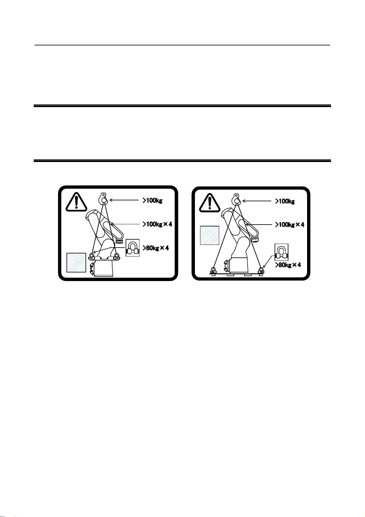
(1) Transportation label
(except 7C/7LC) (7C/7LC)
Fig. 4 (a) Transportation label
Description
When transporting the robot, observe the instructions indicated on this label.
1) Use a crane having a load capacity of 100 kg or greater.
2) Use at least four slings each having a load capacity of 100 kg or greater.
3) Use at least four shackles and eyebolts each having an allowable load of 784 N (80 kgf) or greater.
s-3
Page 25
SAFETY PRECAUTIONS B-83494EN/06
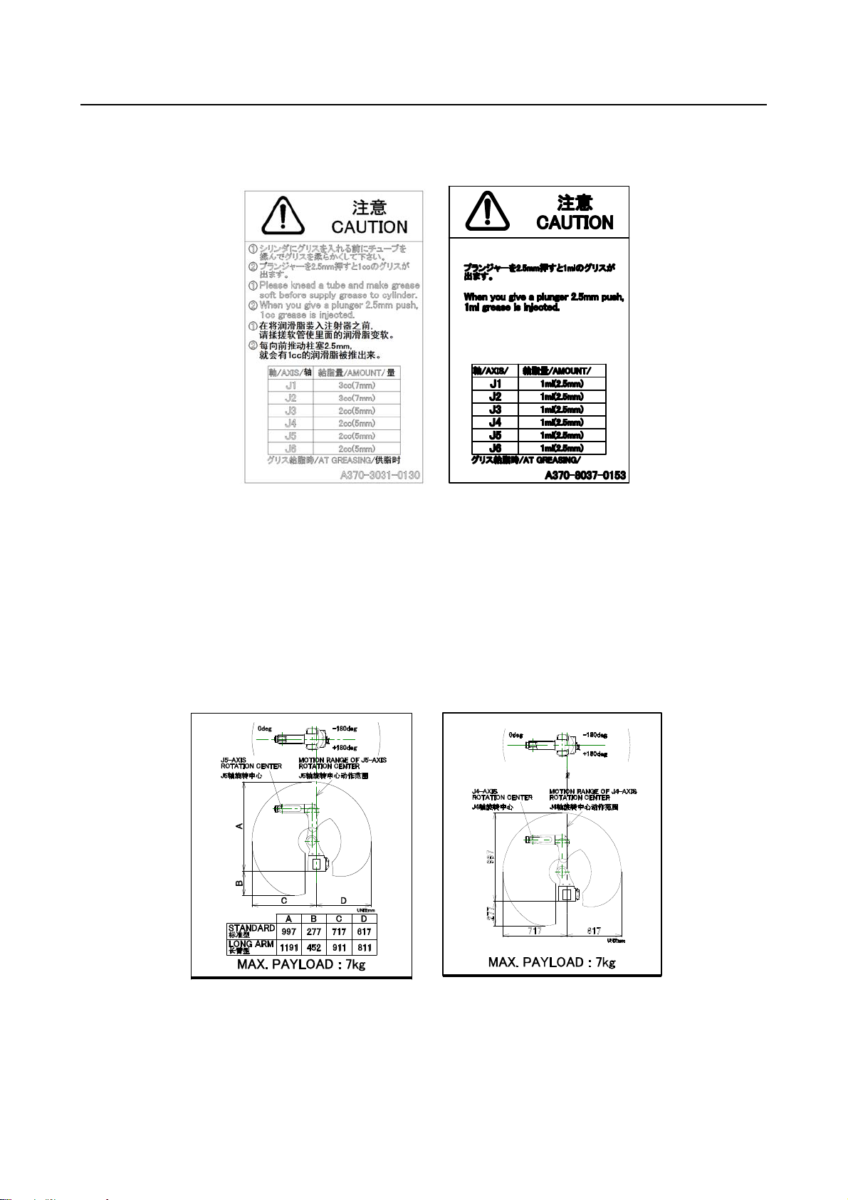
(2) Greasing label
(if greasing kit A05B-1142-K021, A05B-1142-K023 is specified)
每向前推动柱塞
就会有
(Except 7C/7L) (7C/7LC)
Fig. 4 (b) Greasing label
2.5mm,
1ml
的润滑脂被推出来。
轴
量
供脂时
Description
When using a grease kit, observe the instructions indicated on this label.
1) Before filling the cylinder with grease from tube, squeeze the tube to make the grease in it soft.
2) Pushing in the plunger by 2.5 mm causes a grease of 1 ml to be pushed out.
(3) Operation space and payload label
The following label is added if the CE specification is requested.
(Except 7H) (7H)
Fig. 4 (c) Operation space and payload label
s-4
Page 26
B-83494EN/06 PREFACE
PREFACE
This manual explains maintenance procedures for the following mechanical units:
Model name
FANUC Robot LR Mate 200iD
FANUC Robot LR Mate 200iD/7H
FANUC Robot LR Mate 200iD/7C
FANUC Robot LR Mate 200iD/7WP
FANUC Robot ARC Mate 50iD
FANUC Robot LR Mate 200iD/7L
FANUC Robot LR Mate 200iD/7LC
FANUC Robot ARC Mate 50iD/7L
NOTE
The following abbreviations are used herein.
STANDARD : LR Mate 200iD, ARC Mate 50iD
7H : LR Mate 200iD/7H
7C : LR Mate 200iD/7C
7WP : LR Mate 200iD/7WP
7L : LR Mate 200iD/7L, ARC Mate 50iD/7L
7LC : LR Mate 200iD/7LC
Mechanical unit
specification No.
A05B-1142-B201
A05B-1142-B211 5-axes type
A05B-1142-B221 Clean type
A05B-1142-B231 For washing
A05B-1142-B251
A05B-1142-B301 Long arm type
A05B-1142-B321 Long arm, clean type
A05B-1142-B351
Maximum load Remarks
7kg
Long arm type
p-1
Page 27
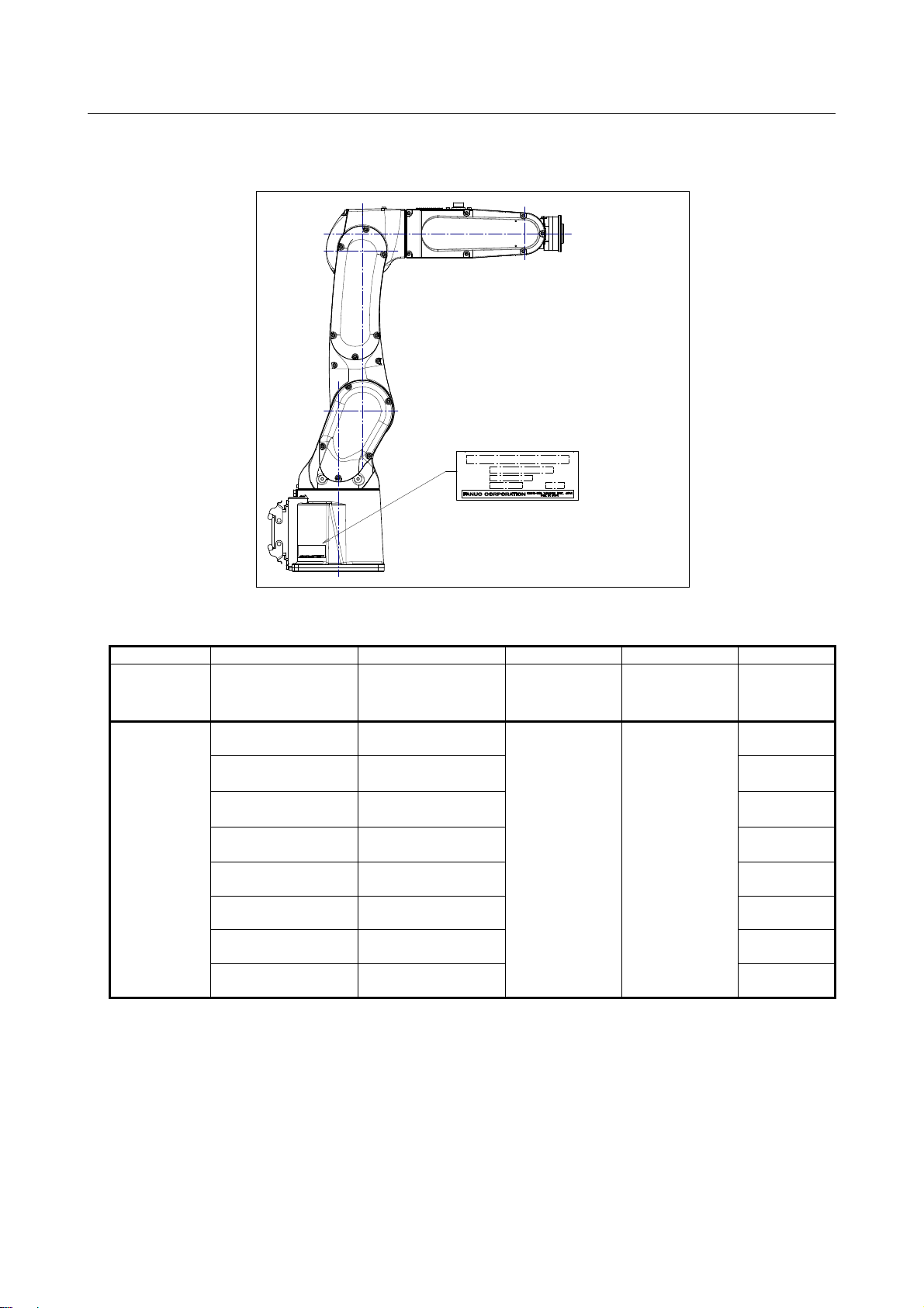
PREFACE B-83494EN/06
The label stating the mechanical unit specification number is affixed in the position shown below. Before
reading this manual, verify the specification number of the mechanical unit.
(1)
TYPE
DATE
(2)
(3)
WEIGHTNO.
(4)
(5)
kg
Position of label indicating mechanical unit specification number
TABLE 1)
(1) (2) (3) (4) (5)
CONTENTS Model name TYPE No. DATE
LETTERS
FANUC Robot
LR Mate 200iD
FANUC Robot
LR Mate 200iD/7H
FANUC Robot
LR Mate 200iD/7C
FANUC Robot
LR Mate 200iD/7WP
FANUC Robot
ARC Mate 50iD
FANUC Robot
LR Mate 200iD/7L
FANUC Robot
LR Mate 200iD/7LC
FANUC Robot
ARC Mate 50iD/7L
A05B-1142-B201 25
A05B-1142-B211 24
A05B-1142-B221 25
A05B-1142-B231 25
A05B-1142-B251 25
SERIAL NO. IS
PRINTED
PRODUCTION
YEAR AND
MONTH ARE
PRINTED
A05B-1142-B301 27
A05B-1142-B321 27
A05B-1142-B351
WEIGHT
(Without
controller)
27
kg
p-2
Page 28
B-83494EN/06 PREFACE
RELATED MANUALS
For the FANUC Robot series, the following manuals are available:
SAFETY HANDBOOK B-80687EN
All persons who use the FANUC Robot and system
designer must read and understand
thoroughly this handbook
R-30iB Mate
R-30iB Mate Plus
controller
MAINTENANCE MANUAL
OPERATOR’S MANUAL
Basic Operation
B-83284EN
Alarm Code List
B-83284EN-1
Optional Function
B-83284EN-2
Standard : B-83525EN
Open Air : B-83555EN
This manual uses following terms.
Name Terms in this manual
Connection cable between robot and controller Robot connection cable
Robot mechanical unit Mechanical unit
Intended readers :
Operator, system designer
Topics :
Safety items for robot system design, operation,
maintenance
Intended readers :
Operator, programmer, maintenance engineer, system
designer
Topics :
Robot functions, operations, programming, setup,
interfaces, alarms
Use :
Robot operation, teaching, system design
Intended readers :
Maintenance engineer, system designer
Topics :
Installation, start-up, connection, maintenance
Use :
Installation, start-up, connection, maintenance
p-3
Page 29

Page 30

B-83494EN/06 TABLE OF CONTENTS
TABLE OF CONTENTS
SAFETY PRECAUTIONS............................................................................s-1
PREFACE....................................................................................................p-1
1 TRANSPORTATION AND INSTALLATION ...........................................1
1.1 TRANSPORTATION......................................................................................1
1.2 INSTALLATION.............................................................................................6
1.2.1 Angle of Mounting Surface Setting..........................................................................9
1.3 MAINTENANCE AREA................................................................................11
1.4 INSTALLATION CONDITIONS....................................................................11
2 CONNECTION WITH THE CONTROLLER ..........................................12
2.1 CONNECTION WITH THE CONTROLLER.................................................12
3 BASIC SPECIFICATIONS.....................................................................14
3.1 ROBOT CONFIGURATION.........................................................................14
3.1.1 Note of Severe Dust /Liquid Specification.............................................................18
3.1.2 Cautions in Selecting the 7WP...............................................................................18
3.1.3 Cautions for 7C/7LC..............................................................................................20
3.1.4 IP69K (option)........................................................................................................20
3.2 MECHANICAL UNIT OPERATION AREA AND INTERFERENCE AREA...21
3.3 ZERO POINT POSITION AND MOTION LIMIT...........................................23
3.4 WRIST LOAD CONDITIONS.......................................................................29
3.5 LOAD CONDITION ON EQUIPMENT MOUNTING FACE..........................33
3.6 OPERATING AREA FOR INCLINATION INSTALLATION ..........................34
4 EQUIPMENT INSTALLATION TO THE ROBOT..................................36
4.1 END EFFECTOR INSTALLATION TO WRIST............................................36
4.2 EQUIPMENT MOUNTING FACE ................................................................36
4.3 LOAD SETTING ..........................................................................................38
4.4 HIGH INERTIA MODE (OPTION) (LR Mate 200iD/7H)...............................40
5 PIPING AND WIRING TO THE END EFFECTOR.................................41
5.1 AIR SUPPLY (OPTION) ..............................................................................42
5.2 INSTALLING THE AIR PURGE KIT ............................................................47
5.3 INTERFACE FOR OPTION CABLE ............................................................51
6 AXIS LIMIT SETUP...............................................................................54
6.1 SOFTWARE SETTING CHANGE AXIS LIMIT BY DCS (OPTION).............54
7 CHECKS AND MAINTENANCE ...........................................................58
7.1 CHECKS AND MAINTENANCE..................................................................58
7.1.1 Daily Checks ..........................................................................................................58
7.1.2 Periodic Check and Maintenance...........................................................................59
c-1
Page 31

TABLE OF CONTENTS B-83494EN/06
7.2 CHECK POINTS..........................................................................................61
7.2.1 Confirmation of Oil Seepage..................................................................................61
7.2.2 Confirmation of the Air Control Set and Air Purge kit (option)............................62
7.2.3 Check the Connectors.............................................................................................63
7.2.4 Check of Mechanical Stopper ................................................................................63
7.3 MAINTENANCE...........................................................................................64
7.3.1 Replacing the Batteries
(1-Year Periodic Inspection If Built-in Batteries Are Specified)
(1.5-Year Periodic Inspection If External Batteries Are Specified).......................64
7.3.2 Replenish the Grease of the Reducer
(4 years (15360 hours) or 2 years (7680 hours) checks)........................................67
7.4 CLEANING THE ROBOT (7C/7LC).............................................................69
7.5 STORAGE...................................................................................................70
8 MASTERING.........................................................................................71
8.1 OVERVIEW .................................................................................................71
8.2 RESETTING ALARMS AND PREPARING FOR MASTERING...................73
8.3 ZERO POSITION MASTERING ..................................................................74
8.4 QUICK MASTERING...................................................................................77
8.5 QUICK MASTERING FOR SINGLE AXIS...................................................80
8.6 SINGLE AXIS MASTERING........................................................................83
8.7 MASTERING DATA ENTRY........................................................................86
8.8 VERIFYING MASTERING...........................................................................88
9 TROUBLESHOOTING ..........................................................................89
9.1 TROUBLESHOOTING.................................................................................89
APPENDIX
A PERIODIC MAINTENANCE TABLE.....................................................97
B STRENGTH OF BOLT AND BOLT TORQUE LIST............................104
C OPTIONAL CONNECTOR WIRING PROCEDURE............................105
D INSULATION ABOUT ARC WELDING ROBOT.................................106
D.1 INSULATION AT THE WRIST...................................................................106
c-2
Page 32

1. TRANSPORTATION
A
B-83494EN/06
AND INSTALLATION
1 TRANSPORTATION AND INSTALLATION
1.1 TRANSPORTATION
Use a crane to transport the robot. When transporting the robot, be sure to change the posture of the robot
to that shown below and lift by using the eyebolts and the transport equipment at their points.
WARNING
1 The robot becomes unstable when it is transported with the end effector applied
to wrist. Please be sure to remove the end effector when the robot is
transported.
2 Before moving the robot with a crane, check and tighten any loose bolts on the
transport equipment on the robot.
3 Do not pull eyebolts sideways.
Transportation using a crane (Fig. 1.1 (a) to (f))
Fasten the transport equipment to the robot base and lift the robot with the four slings.
CAUTION
Note that slings with insufficient length may break the J2 base or J2 arm cover.
Crane
クレーン
クレーン許容荷重:500kg以上
Transport
輸送部材
equipment
Shackle
シャックル
235
注)
Note)
1. Mechanical unit mass: 25kg (Standard/7WP)
1. 機構部質量:25kg (標準,7WP)
24kg (7H)
2. Shackle complied with JIS B 2801.
2. シャックル JIS B 2801に準ずるものを使用
3. Quantity Shackle:4 Sling:4
3. 使用数 シャックル:4 スリング:4
24kg (7H)
Fig. 1.1 (a) Transportation using a crane (back side connector plate)
207
(Standard/7H/7WP)
- 1 -
191
Sling
スリング
スリング許容荷重:100kg以上
Crane
Load capacity.: 100kg or more
Sling
Load capacity. : 100kg/sling or more
Shackle
llowable load. : 80kgf/each or more
Transport
703
輸送姿勢
posture
(標準,7WP)
(Standard/ 7WP)
J1: 0°
J2:-30°
J3:-40°
J4: 0°
J5:-45°
J6: 0°
Transport posture
(7H Downward wrist
zero specification)
Transport posture
(7H Horizontal wrist
輸送姿勢
(7H 手首水平が0°)
zero specification)
J1: 0°
J2:-30°
J3:-40°
J4:-45°
J5: 0°
輸送姿勢
(7H 手首下向きが0°)
J1: 0°
J2:-30°
J3:-40°
J4: 5°
J5: 0°
Page 33

1. TRANSPORTATION
A
AND INSTALLATION
B-83494EN/06
クレーン
Crane
クレーン許容荷重:500kg以上
スリング
Sling
スリング許容荷重:100kg以上
Crane
Load capacity.: 100kg or more
Sling
Load capacity. : 100kg/sling or more
Shackle
llowable load. : 80kgf/each or more
Transport
輸送姿勢
posture
(標準,7WP)
786
(Standard/7WP)
J1: 0°
J2:-30°
J3:-40°
J4: 0°
J5:-45°
J6: 0°
Transport posture
(7H Downward wrist
zero specification)
Transport posture
(7H Horizontal wrist
輸送姿勢
zero specification)
(7H 手首水平が0°)
J1: 0°
J2:-30°
J3:-40°
J4:-45°
J5: 0°
輸送姿勢
(7H 手首下向きが0°)
J1: 0°
J2:-30°
J3:-40°
J4: 5°
J5: 0°
Shackle
シャックル
Transport
輸送部材
equipment
Stand
スタンド
190
235
Note)
注)
1. Mechanical unit mass: 25kg (Standard/7WP)
1. 機構部質量:25kg (標準,7WP)
24kg (7H)
2. Shackle complied with JIS B 2801.
2. シャックル JIS B 2801に準ずるものを使用
3. Quantity Shackle:4 Sling:4
3. 使用数 シャックル:4 スリング:4
24kg (7H)
Fig. 1.1 (b) Transportation using a crane (bottom connector plate)
(Standard/7H/7WP)
130 130
207 191
- 2 -
Page 34

1. TRANSPORTATION
A
A
B-83494EN/06
クレーン
Crane
クレーン許容荷重:500kg以上
Transport
輸送部材
equipment
Shackle
シャックル
235
Note)
注)
1. Mechanical unit mass: 27kg
1. 機構部質量:27kg
2. Shackle complied with JIS B 2801.
2. シャックル JIS B 2801に準ずるものを使用
3. Quantity Shackle:4 Sling:4
3. 使用数 シャックル:4 スリング:4
217 246
Fig. 1.1 (c) Transportation using a crane (back side connector plate) (7L)
クレーン
Crane
クレーン許容荷重:500kg以上
AND INSTALLATION
Sling
スリング
スリング許容荷重:100kg以上
Crane
Load capacity.: 100kg or more
Sling
Load capacity. : 100kg/sling or more
Shackle
llowable load. : 80kgf/each or more
798
Transport
posture
輸送姿勢
J1: 0°
J2:-30°
J3:-40°
J4: 0°
J5:-50°
J6: 0°
シャックル
Shackle
190
235
Note)
注)
1. Mechanical unit mass: 27kg
1. 機構部質量:27kg
2. Shackle complied with JIS B 2801.
2. シャックル JIS B 2801に準ずるものを使用
3. 使用数 シャックル:4 スリング:4
3. Quantity Shackle:4 Sling:4
Fig. 1.1 (d) Transportation using a crane (bottom connector plate) (7L)
Transport
輸送部材
equipment
130 130
217 246
スリング
Sling
スリング許容荷重:100kg以上
Crane
Load capacity.: 100kg or more
Sling
Load capacity. : 100kg/sling or more
Shackle
llowable load. : 80kgf/each or more
798
Transport
posture
輸送姿勢
J1: 0°
J2:-30°
J3:-40°
J4: 0°
J5:-50°
J6: 0°
- 3 -
Page 35

1. TRANSPORTATION
A
AND INSTALLATION
B-83494EN/06
Crane
Tape
テープ
(for clean room)
(クリーンルーム用)
クレーン
Sling
スリング
Crane
クレーン
Load capacity.: 100kg or more
可搬質量: 100kg以上
Sling
Load capacity. : 100kg/sling or more
スリング
可搬質量: 100kg/本以上
Eyebolt
llowable load. : 80kgf/each or more
アイボルト
許容荷重: 80kgf/個以上
輸送姿勢
Transport posture
J1: 0°
J2:-30°
J3:-40°
J4: 0°
J5:-45°
J6: 0°
Plastic bag
プラスチック袋
A290-7134-X918 (1)
A290-7134-X918 (1)
727
Plastic bag
プラスチック袋
A290-7134-X918 (1)
A290-7134-X918 (1)
Fix with tape
テープにて固定すること。
Eyebolt (M10)
アイボルト (M10)
JB-BEY-10SS41-M-ZN (4)
JB-BEY-10SS41-M-ZN (4)
380
注)
Note)
1 機構部質量:25kg
1 Mechanical unit mass: 25 kg
2 アイボルト JIS B 1168に準ずるものを使用
3 使用数 アイボルト:4 スリング:4
2 Eyebolt complied with JIS B 1168.
3 Quantity Eyebolt:4 Sling:4
テープ(クリーンルーム用)
Tape (for clean room)
Fig. 1.1 (e) Transportation using a crane (7C)
570
Transport
輸送部材
equipment
- 4 -
Page 36

1. TRANSPORTATION
A
B-83494EN/06
クレーン
Crane
Sling
スリング
Tape
テープ
(クリーンルーム用)
(for clean room)
AND INSTALLATION
Crane
クレーン
Load capacity.: 100kg or more
可搬質量: 100kg以上
Sling
Load capacity. : 100kg/sling or more
スリング
可搬質量: 100kg/本以上
Eyebolt
llowable load. : 80kgf/each or more
アイボルト
許容荷重: 80kgf/個以上
Transport posture
輸送姿勢
J1: 0°
J2:-30°
J3:-40°
J4: 0°
J5:-50°
J6: 0°
820
Plastic bag
プラスチック袋
A290-7134-X918 (1)
A290-7134-X918
Plastic bag
プラスチック袋
A290-7134-X918
A290-7134-X918 (1)
テープにて固定すること。
Fix with tape
アイボルト (M10)
Eyebolt (M10)
JB-BEY-10SS41-M-ZN (4)
JB-BEY-10SS41-M-ZN (4)
380
テープ(クリーンルーム用)
注)
Note)
1 機構部質量:27kg
1 Mechanical unit mass: 27 kg
2 アイボルト JIS B 1168に準ずるものを使用
2 Eyebolt complied with JIS B 1168
3 使用数 アイボルト:4 スリング:4
3 Quantity Eyebolt:4 Sling:4
Tape (for clean room)
570
Transport
輸送部材
equipment
Fig. 1.1 (f) Transportation using a crane (7LC)
NOTE
About the LR Mate 200iD/7C/7LC
1 Before shipment of the LR Mate 200iD/7C/7LC, it is cleaned in a clean room,
covered with an antistatic sheet, then packed as shown in Fig. 1.1 (e),(f).
2 The transport plate can be used as a roll–over prevention plate in a clean room.
If the plate is cleaned before being carried in a clean room, it can be carried in
the room together with the robot.
3 The antistatic sheet can be removed in a clean room.
4 When installing the robot, use the eyebolts to lift it as shown Fig. 1.1 (e), (f).
5 Once the robot has been installed, remove the eyebolts from it.
6 After transportation, be sure to fix it as described in Section 1.2.
- 5 -
Page 37

1. TRANSPORTATION
AND INSTALLATION
B-83494EN/06
1.2 INSTALLATION
Fig. 1.2 (a), (b) show the robot base dimensions.
Fig.1.2 (c) shows the dimensions of the connector cover for the IP69K option.
CAUTION
Flatness of robot installation surface must be less than or equal to 0.5mm.
Inclination of robot installation surface must be less than or equal to 0.5
If robot base is placed on uneven ground, it may result in the base breakage or
low performance of the robot.
Front
正面
J1-axis
J1軸旋回中心
15
7()13()
165
82.5
rotation center
through
4-O11 貫通
82.5
.
°
198200
190
95
7() 13()
7() 13()
95
190
165
7()
13()
Locating surface
突き当て面
Fig. 1.2 (a) Dimensions of the robot base (back side connector plate)
- 6 -
Page 38

1. TRANSPORTATION
B-83494EN/06
Front
正面
165
82.5
J1-axis
J1軸旋回中心
rotation center
4-O11 貫通
2
9
R
*
82.5
through
200
AND INSTALLATION
15
190
35*
1*
2
95
R
*
5
1
2
°
R
*
°
5
3
*
92*
*) Please be careful to the interference of the mounting holes and the bolts.
*) 設置面の取り付け穴とボルトの干渉にご注意下さい。
95
190
Fig. 1.2 (b) Dimensions of the robot base (bottom connector plate)
190
95
190
95
165
突き当て面
Locating surface
95
Connector
コネクタカバー
cover
157
23 144
23
Robot connector
ロボット接続
cable
ケーブル
Fig. 1.2 (c) Dimensions of the connector cover for IP69K option (back side connector plate)
NOTE
Bottom connector plate does not have the connector cover.
- 7 -
154
173
Cable tie
ケーブルタイ
Page 39

1. TRANSPORTATION
AND INSTALLATION
B-83494EN/06
Fig. 1.2 (d), Table 1.2 (a) to Table 1.2 (d) indicate the force and moment applied to the base plate at the
time of Power-Off stop of the robot and indicate the stopping distance and time of the J1 through J3 axes
until the robot stopping by Power-Off stop or by Controlled stop after input of the stop signal.
Refer to the data when considering the strength of the installation face.
Table 1.2 (a) Force and moment that acts on J1 base (Standard/7H/7WP/7C)
Horizontal
moment
Mh(Nm)
During stillness
During acceleration or
deceleration
During Power-Off stop
Vertical moment
Mv(Nm)
115.5 313.6 0 0
605.2 595.2 289.1 860.3
768.3 1054.6 402.2 1100.1
Force in Vertical
direction
Fv(N)
Table 1.2 (b) Force and moment that acts on J1 base (7L/7LC)
During stillness
During acceleration or
deceleration
During Power-Off stop
Vertical moment
Mv(Nm)
147.3 333.2 0 0
439.8 602.1 336.3 784.8
1657.2 1612.7 1285.6 1656.8
Force in Vertical
direction
Fv(N)
Horizontal
moment
Mh(Nm)
Table 1.2 (c) Stopping time and distance until the robot stopping by Power-Off stop after input of stop signal
J1 J2 J3
Standard/7WP/7C
7H
7L/7LC
Stopping time [ms] 348 284 332
Stopping angle [deg] (rad) 82.1 (1.43) 43.0 (0.75) 63.7 (1.11)
Stopping time [ms] 372 300 398
Stopping angle [deg] (rad) 77.2 (1.35) 45.9 (0.80) 65.3 (1.14)
Stopping time [ms] 372 364 324
Stopping angle [deg] (rad) 69.0 (1.20) 57.3 (1.00) 54.4 (0.95)
* Max payload and max speed
Table 1.2 (d) Stopping time and distance until the robot stopping by Controlled stop after input of stop signal
J1 J2 J3
Standard/7WP/7C
7H
7L/7LC
Stopping time [ms] 516 516 540
Stopping angle [deg] (rad) 128.4 (2.24) 92.0 (1.61) 122.7 (2.14)
Stopping time [ms] 516 508 524
Stopping angle [deg] (rad) 129.0 (2.25) 92.6 (1.62) 124.1 (2.16)
Stopping time [ms] 524 508 540
Stopping angle [deg] (rad) 106.9 (1.86) 79.6 (1.39) 117.9 (2.06)
* Max payload and max speed
Force in
Horizontal direction
Fh(N)
Force in
Horizontal direction
Fh(N)
Mv
Fv
Fh
Fig. 1.2 (d) Force and moment that acts on J1 base
Mh
- 8 -
Page 40

1. TRANSPORTATION
B-83494EN/06
AND INSTALLATION
1.2.1 Angle of Mounting Surface Setting
If robot is used except floor mount, be sure to set the mounting angle referring to the procedure below.
Refer to specifications in Section 3.1 for installation type.
1 Turn on the controller with the [PREV] and the [NEXT] key pressed. Then select [3 Controlled
start].
2 Press the [MENU] key and select “9 MAINTENANCE”.
3 Select the robot for which you want to set the mount angle and press the [ENTER] key.
ROBOT MAINTENANCE CTRL START MANU
Setup Robot System Variables
Group R obo t Libr ar y/Opti on Ext A xes
1 LR Mate 200iD 0
[TYPE]ORD NO AUTO MANUAL
4 Press the [F4] key.
5 Press the [ENTER] key until screen below is displayed.
*******Group 1 I nit ia liz ation************
************* LR Mat e 200 iD*************
--- MOUNT ANG LE SET TI NG ---
0 [deg] : f loo r m ou nt type
90 [deg] : w all mo un t t ype
180 [deg] : u psi de- do wn mount type
Set mount_ang le (0- 18 0[d eg])->
Default va lue = 0
- 9 -
Page 41

1. TRANSPORTATION
AND INSTALLATION
B-83494EN/06
6 Input the mount angle referring to Fig. 1.2.1. 7H Downward wrist zero specification is restricted to
floor mount and upside-down mount.
+
Angle of
設置角度
mounting face
Fig. 1.2.1 Robot mounting angle
7 Press the [ENTER] key until the screen below is displayed again.
ROBOT MAI NT ENA NCE CTRL START MAN U
Setup Ro bo t S ystem Variables
Gro up R obo t L ibrary/Option Ext Axes
1 LR Ma te 200iD 0
[TYPE]ORD NO AUTO MANUAL
8 Press the [FCTN] key and select ”1 START (COLD)”.
- 10 -
Page 42

1. TRANSPORTATION
B-83494EN/06
AND INSTALLATION
1.3 MAINTENANCE AREA
Fig.1.3 shows the maintenance area of the mechanical unit. Be sure to leave enough room for the robot to
be mastered. See Chapter 8 the mastering.
500
190
500
500
(In case of bottom
(底面分線盤の場合)
connector plate)
500
Fig. 1.3 Maintenance area
(*)
(*)
(*)
620 (Standard/7H/7C/7WP)
620 (標準/7H/7C/7WP)
705 (7L/7LC)
705 (7L/7LC)
1.4 INSTALLATION CONDITIONS
250
500
Refer to the caution below concerning installation conditions.
Refer to also to the specifications found in Section 3.1 and Section 3.2.
CAUTION
1 When external battery option is specified, please fix the battery box in the part
without the vibration, and do measures of a protection against dust and liquid.
2 Damage of coating of robot connection cable and external battery cable can
causes water intrusion. Take care when installing the cable and exchange it if it
is damaged.
- 11 -
Page 43

Page 44

2. CONNECTION WITH THE CONTROLLER B-83494EN/06
2 CONNECTION WITH THE CONTROLLER
2.1 CONNECTION WITH THE CONTROLLER
The robot is connected with the controller via the power cable and signal cable. Connect these cables to
the connectors on the back of the robot base. Please be sure to connect the earth cable.
For details on air and option cables, see Chapter 5.
WARNING
Before turning on controller power, be sure to connect the robot and controller
with the earth line (ground). Otherwise, there is the risk of electrical shock.
CAUTION
1 Before connecting the cables, be sure to turn off the controller power.
2 Don’t use 10m or longer coiled cable without first untying it. The long coiled
cable will heat up and become damaged.
3 If external batteries are in use, do not remove it with the power supply turned off.
Replacing the batteries with the power supply turned off causes all current
position data to be lost. Therefore, mastering will be required again.
Controller
Robot
cable for power and signal
earth cable
Air
Connector for
power and signal
Earth
Detail A
A
Fig. 2.1 (a) Cable connection (back side connector plate)
- 12 -
Page 45

B-83494EN/06 2. CONNECTION WITH THE CONTROLLER
Robot
Controller
cable for power and brake
earth cable
Air
Connector for
power and signal
Earth
Detail A
Fig. 2.1 (b) Cable connection (bottom connector plate)
A
- 13 -
Page 46

3. BASIC SPECIFICATIONS B-83494EN/06
3 BASIC SPECIFICATIONS
3.1 ROBOT CONFIGURATION
J3 housing
J3ハウジング
J5-axis motor
J4-axis motor
J4軸モータ
J2 arm
J2ベース
J2 base
J5軸モータ
J2アーム
J3-axis motor
J3軸モータ
J2-axis motor
J2軸モータ
J6-axis motor
J6軸モータ
J3 arm
End effector
エンドエフェクタ取付面
mounting face
手首ユニット
Wrist unit
J3アーム
J1 base
J1ベース
J1-axis motor
J1軸モータ
Fig. 3.1 (a) Mechanical unit configuration (Except 7H)
J3ハウジング
J3 housing
J4-axis motor
J4軸モータ
J5-axis motor
J2 arm
J2アーム
J3軸モータ
J3-axis motor
J2-axis motor
J2軸モータ
J2ベース
J2 base
J5軸モータ
J3 arm
J3アーム
End effector
mounting face
エンドエフェクタ
取付面
Wrist unit
手首ユニット
J1 base
J1ベース
J1-axis motor
J1軸モータ
Fig. 3.1 (b) Mechanical unit configuration (7H)
- 14 -
Page 47

B-83494EN/06 3. BASIC SPECIFICATIONS
-
-
X
J6
Y
-
-
Z
+
+
J5
-
-
J4
J4
+
+
+
+
+
+
J3
J3
-
J2
J2
-
-
++
-
-
J1
J1
*All axes are 0°at this posture
Fig. 3.1 (c) Each axis coordinates and mechanical interface coordinates (Except 7H)
X
J5
Y
-
-
Z
+
+
+
+
J4
-
-
+
+
+
+
J3
J3
-
J2
J2
-
-
+
+
-
-
J1
J1
*All axes are 0°at this posture
Fig. 3.1 (d) Each axis coordinates and mechanical interface coordinates
(7H Horizontal wrist zero specification)
- 15 -
+
+
Page 48

3. BASIC SPECIFICATIONS B-83494EN/06
+
+
+
+
Y
J3
J3
J4
-
-
X
J5
-
+
Z
+
+
-
-
J1
J1
+
+
*All axes are 0°at this posture
Fig. 3.1 (e) Each axis coordinates and mechanical interface coordinates
(7H Downward wrist zero specification)
NOTE
The end effector mounting face center is 0, 0, 0 of the mechanical interface
coordinates.
J2
J2
-
-
- 16 -
Page 49

B-83494EN/06 3. BASIC SPECIFICATIONS
A
A
Table 3.1 Specifications
Item Specifications
LR Mate 200iD
Model
Type Articulated Type
Controlled axis 6-axis(J1, J2, J3, J4, J5, J6) 5-axis(J1, J2, J3, J4, J5) 6-axis(J1, J2, J3, J4, J5, J6)
Reach 717mm 911mm
Installation (NOTE 1) Floor, Upside-down (Angle mount)
J1-axis
J2-axis
Motion range
(Max. speed)
(NOTE 2)
Max. load capacity
(NOTE 3)
Allowable load
moment at wrist
Allowable load
inertia at wrist
Drive method Electric servo drive by AC servo motor
Repeatability (NOTE 5)
Mass (NOTE 6) 25kg 24kg 27kg
Dust proof and drip proof
mechanism (NOTE 7)
Acoustic noise level 64.7dB (Note 8)
Installation environment
J3-axis
J4-axis
J5-axis
J6-axis
Wrist 7 kg
J4-axis 16.6Nm 16.6Nm 16.6Nm
J5-axis 16.6Nm
J6-axis 9.4Nm 9.4Nm
J4-axis 0.47kgxm2 0.47 kgxm2 0.47kgxm2
J5-axis 0.47kgxm2
J6-axis 0.15kgxm
ARC Mate 50iD
LR Mate 200iD/7C
LR Mate 200iD/7WP
340°/360°(option) (450°/s)
5.93rad/6.28rad(option) (7.85rad/s)
245° (380°/s)
4.28rad (6.63rad/s)
420° (520°/s)
7.33rad (9.08rad/s)
380° (550°/s)
6.63rad (9.60rad/s)
250° (545°/s)
4.36rad (9.51rad/s)
720° (1000°/s)
12.57rad (17.45rad/s)
2
0.15kgxm2
Conform to IP67 (Option :IP69K) (Except 7C/7LC)
Conform to IP67 , Class 10 (ISO class 4) (Option :IP69K) (7C/7LC)
*7LC does not support IP69K option
mbient temperature: 0 - 45°C (NOTE 9)
mbient humidity: Normally 75%RH or less. No dew, nor frost allowed.
Short time (within one month) Max 95%RH
Height: Up to 1000 meters above the sea level required,
no particular provision for posture.
Vibration acceleration : 4.9m/s
Free of corrosive gases (NOTE 10)
LR Mate 200iD/7H
250° (545°/s)
4.36rad (9.51rad/s)
720° (1500°/s)
12.57rad (26.18rad/s)
5.5Nm (NOTE 4)
0.046 kgxm
0.15 kgxm2 (NOTE 4)
±0.01mm
2
(0.5G) or less
4.0Nm
2
LR Mate 200iD/7L
ARC Mate 50iD/7L
LR Mate 200iD/7LC
340°/360°(option) (370°/s)
5.93rad/6.28rad(option)
(6.45rad/s)
245° (310°/s)
4.28rad (5.41rad/s)
430° (410°/s)
7.50rad (7.15rad/s)
380° (550°/s)
6.63rad (9.60rad/s)
250° (545°/s)
4.36rad (9.51rad/s)
720° (1000°/s)
12.57rad (17.45rad/s)
16.6Nm
0.47kgxm
2
NOTE 1) Under the installation condition within ( ), the J1 and J2 axis motion rang e will be limited. See Section
3.6. 7H Downward wrist zero specification is restricted to floor mount and upside-down mount.
NOTE 2) During short distance motions, the axis speed may not reach the maximum value stated.
NOTE 3) The all up weight including the equipment and connection cables and its swing must not exceed this
value when you install the equipment. Section 3.5.
NOTE 4) This value is for high inertia mode. Please refer to Section 4.4 about change method.
NOTE 5) Compliant with ISO 9283.
NOTE 6) It doesn't contain the mass of the control part.
NOTE 7) The liquid that is the deterioration of the seal material such as Organic solvent, acid, alkali and chlorine
system, cutting liquid cannot be use. (See Subsection 3.1.1.)
NOTE 8) This value is equivalent continuous A-weighted sound pressure level that applied with ISO11201
(EN31201). This value is measured with the following conditions.
- Maximum load and speed
- Operating mode is AUTO
NOTE 9) When robot is used in low temperature environment that is near to 0ºC, or robot is not operated for a
long time in the environment that is less than 0ºC in a holiday or the night, because viscous resistance of
the drive train is so big that may cause occurrence of collision detect alarm (SRVO –050) etc. In this
case, we recommend performing the warm up operation for several minutes.
NOTE 10) Contact the service representative, if the robot is to be used in an environment or a place subjected to
severe vibrations, heavy dust, cutting oil splash and or other foreign substances.
- 17 -
Page 50

3. BASIC SPECIFICATIONS B-83494EN/06
3.1.1 Note of Severe Dust /Liquid Specification
1 The liquids below cannot be applied because they may cause deterioration or corrosion of the rubber
parts (such as gaskets, oil seals, and O-rings) used in the robot.
(a) Organic solvent
(b) Chlorine-based cutting fluid
(c) Amine-based cleaning fluid
(d) Liquid or solution that includes a corrosive such as an acid or alkali or causes rust
(e) Some other liquid or solution to which nitrile rubber (NBR) does not have resistance
2 When the robot is used in an environment where a liquid such as water is dashed over the robot,
great attention should be given to drainage under the J1 base. A failure may be caused if the J1 base
is kept immersed in water due to poor drainage.
3 Gaskets can be reused.
4 Don’t use unconfirmed liquid.
3.1.2 Cautions in Selecting the 7WP
The 7WP specifies cleaning fluids usable with the robot. (Always keep all the liquids at or below 60°C.)
Liquid model name Manufacturer name Permissible concentration
Lub clean 54 TOHO Chemical Industry Co., LTD.
Sun cleaner G-2000B SUGIMURA Chemical Industry Co., LTD.
Sun cleaner G-2100S SUGIMURA Chemical Industry Co., LTD.
Sun cleaner G-2300F SUGIMURA Chemical Industry Co., LTD.
Toyosol SE-78P Toyoda Chemical Industry Co., Ltd.
Toyosol SE-91P Toyoda Chemical Industry Co., Ltd.
Toyoknock R747P Toyoda Chemical Industry Co., Ltd.
Toyoknock RE-777P Toyoda Chemical Industry Co., Ltd.
Detergent 2000 NEOS Co., LTD.
Packna FD-800 YUKEN Industry CO., LTD.
Packna FD-85 YUKEN Industry CO., LTD.
Yushiro cleaner
PCW553
Yushiro cleaner W80
Quakerclean 624CP Quaker Chemical Corporation
YUSHIRO CHEMICAL INDUSTRY CO.,
LTD.
YUSHIRO CHEMICAL INDUSTRY CO.,
LTD.
5%
Diluted to 20 parts of water
3%
Diluted to 50 parts of water
5%
Diluted to 20 parts of water
3%
Diluted to 33 parts of water
5%
Diluted to 20 parts of water
2%
Diluted to 50 parts of water
3%
Diluted to 33 parts of water
3%
Diluted to 33 parts of water
5%
Diluted to 20 parts of water
5%
Diluted to 20 parts of water
3%
Diluted to 33 parts of water
5%
Diluted to 20 parts of water
3.3%
Diluted to 30 parts of water
3%
Diluted to 30 parts of water
Please don’t use the cleaning fluid under the condition over the allowable concentration or temperature.
Reference
pH
10.4
10.0
10.0
10.0
10.5
10.3
10.3
9.5
11.0
9.0
11.0
9.8
9.0
9.7
- 18 -
Page 51

B-83494EN/06 3. BASIC SPECIFICATIONS
Using cleaning fluid other than those above
When using some other cleaning fluid, please choose it carefully in accordance with the following
description.
Choosing cleaning fluid
Please confirm that pH of the cleaning fluid is 8.5 to 11.0. LR Mate 200iD/7WP has a good resistance
against alkali but not acid or neutral.
Confirmation test by using a dipping test kit (A05B-1142-K024)
FANUC provides the dipping test kit (A05B-1142-K024) to confirm the usability of the cleaning fluid.
Test condition is as follows:
Concentration : 1.3 times of the concentration that you plant to use.
Temperature : Test at 5 degrees Celsius higher than specified temperature.
Period : 14 days
If the following situation happens with the test pieces, the liquid doesn’t suit for use. (*1)
Causing precipitate : It may indicate that the test piece dissolves.
Causing corrosion on the metal parts
Changes (swelling, etc.) on the rubber parts
(*1) LR Mate 200iD/7WP doesn’t have painting. Please use only the test pieces without painting.
Management of cleaning fluid
Insufficient management of cleaning fluid causes bad effects such as corrosion on the robot. Please
manage it carefully in accordance with the following description.
Management of pH
Please monitor pH by using pH test paper, etc., and keep pH in 8.5 to 11.0.
PH decrease causes deterioration of cleaning fluid, and it makes the robot parts corroded.
Cleaning filtration of cleaning fluid
x Removing foreign materials
Removing chips and foreign materials with a high efficiency filter, etc. The more chloride ions from
diluted solution accumulate, the more cleaning fluid becomes harmful to the robot. In cases that the
chloride ions may enter from tap water, please take measures such as installation of some removing filter.
x Removing oil from other processes
FANUC recommends installing oil skimmer or oil removal equipment. Other simple ways are as below.
- Absorbing floating ingredients of the oil with non-woven fabric, etc.
- Scooping floating ingredients of the oil by a dedicated container (please use a dedicated one to
prevent other contaminations).
- 19 -
Page 52

3. BASIC SPECIFICATIONS B-83494EN/06
Other verification items
Appearance
Please check the followings of cleaning fluid on a daily basis and find the abnormality beforehand.
Cleanliness / Discoloration / Occurrence of film and sludge
Bad smell
Bad smell occurs when microorganisms are bred. Please check the smell of cleaning fluid on a daily basis.
Examples of typical bad smell are as follows.
Rotten egg smell / Acidulous smell / Moldy smell / Other putrid smell
Concentration
Cleaning fluid is perishable when concentration is decreased, and the robot is also damaged when
cleaning fluid is too much concentrated. Keep the appropriate concentration in reference to the manual of
cleaning fluid.
Refilling of diluted solution
Cleaning fluid is likely to be reduced by splashing or evaporation and carried out with workpieces and
chips. Please refill diluted solution regularly. Refilling before holidays will help to prevent decay of
cleaning fluid and maintain pH and antirust effect.
FANUC recommends making a check-sheet of the above items and recording a management history.
OTHER CAUTIONS
1 The cables connecting the robot, controller, and external battery are not resistant to any cleaning
fluid. So, install them in such a way that no cleaning fluid will be splashed to the cables.
2 Be sure to perform air purge by regulated pressure. (See Section 5.2.) Please do the air purge
whenever the robot is stopping or the power supply is cut. The air purge stop causes the flood and
the be dewy in the mechanism.
3.1.3 Cautions for 7C/7LC
1 As for the clean specification, only the robot mechanical unit satisfies clean class 10. Note that none
of the controller, the cables between the controller and robot, and teach pendant does not meet the
clean specification.
2 When using liquids in cleaning, see 1 and 4 in Subsection 3.1.1.
3 If gaskets are dismounted during parts replacement or inspection, replace them with new ones.
3.1.4 IP69K (option)
Definition of IP69K is below.
Robot are sprayed at high pressure via a flat jet nozzle from at angles of 0°, 30°, 60°, 90°.
- each for at least 30 seconds.
The nozzle is held 100 to 150mm from the robot
- at a water pressure of 80-100 bars and a temperature of 80℃
- the quantity of water is 14-16 L/minute
After testing, water must not be present inside the robot.
- 20 -
Page 53

B-83494EN/06 3. BASIC SPECIFICATIONS
3.2 MECHANICAL UNIT OPERATION AREA AND
INTERFERENCE AREA
Fig. 3.2 (a), (b) show the robot operating space. When installing peripheral equipment, be careful not to
interfere with the robot and its operating space.
-170 DEG
235
227
0
7
R
Operating space
of J5-axis rotation
J5軸中心動作領域
center
0 DEG
7
1
7
R
J5-axis
J5軸回転
rotation
中心
center
997277
80 (*1)
92 (*2)
°
6
-180 DEG(OPTION)
+180 DEG(OPTION)
0
0
2
0
R
15
R
J3-axis rear side
J3軸後部干渉領域
Interference area
352
50335
R
7
°
5
4
1
°
0
3
7
5
°
1
00
°
5
2
8
0
°
2
8
0
°
+170 DEG
330 330 35
190
1
1
2
°
(*1) Except 7C
(*1) 7C以外
(*2) 7C
(*2) 7C
717 617
Fig. 3.2 (a) Operating space
(Standard/7H/7C/7WP)
NOTE
Fig. 3.2 (a) is an example of Standard, please read J5-axis as J4-axis throughout
these figures in case of 7H.
- 21 -
Page 54

3. BASIC SPECIFICATIONS B-83494EN/06
-170 DEG
0 DEG
-180 DEG(OPTION)
+180 DEG(OPTION)
235
227
190
Operating space
of J5-axis rotation
J5軸中心動作領域
center
1
1
9
R
J5-axis
J5軸回転
rotation center
中心
1191452
6
3
2
R
2
8
0
°
J3-axis rear side
J3軸後部干渉領域
Interference area
°
0
8
2
80 (7L)
92 (7LC)
°
°
7
5
4
1
1
1
7
°
50420
510
R
7
5
6
7
°
1
0
0
°
+170 DEG
330 440 35
911 811
Fig. 3.2 (b) Operating space
(7L/7LC)
- 22 -
Page 55

B-83494EN/06 3. BASIC SPECIFICATIONS
3.3 ZERO POINT POSITION AND MOTION LIMIT
A zero point and motion range are provided for each controlled axis. Exceeding the software motion limit
of a controlled axis is called overtravel (OT). Overtravel is detected at both ends of the motion limit for
each axis. The robot cannot exceed the motion range unless there is a loss of the zero point position due
to abnormalities in servo system or a system error.
limit maximum motion and to improve safety.
Fig. 3.3 (a) shows the position of the mechanical stopper. Don’t reconstruct the mechanical stopper. If
you do, there is a possibility that the robot will not stop normally.
J3-axis mechanical stopper
J3軸機械式ストッパ
Spec. :
仕様:
J3 stopper : A290-7142-X427
J3ストッパ:A290-7142-X427
スプリングピン:A6-PS-8X20S
spring ping A6-PS-8X20S
Note : When assembling the J3 stopper
注:J3ストッパをスプリ ングピンに組み
付ける時はセメダイン スーパーX
to the spring pin, apply
(クリア)を塗布して下さい。
CEMEDINE SUPER X (CLEAR)
(Spec. : A98L-0004-0717#C).
In addition, a mechanical stopper is also used to
J1軸機械式ストッパ
J1-axis mechanical stopper
仕様:
Spec. : Spr ing pin : A6-PS-8X20S
スプリングピン:A6-PS-8X20S
断面 A-A
Section A-A
A
A
Fig. 3.3 (a) Position of mechanical stopper
- 23 -
Page 56

3. BASIC SPECIFICATIONS B-83494EN/06
Fig.3.3 (b) to (j) show the zero point, motion limit and maximum stopping distance (stopping distance in
condition of max speed and max load) of each axis.
Only in case of the J1, J3-axis, when the robot comes in contact with the mechanical stopper, it may
deform. When the mechanical stopper is deformed, replacement is needed. See Fig.3.3 (a) about replacing
J3-axis mechanical stopper. Contact FANUC about replacing J1-axis mechanical stopper.
* The motion range can be changed. For information on how to
Chapter 6, "AXIS LIMIT SETUP".
°
0
7
1
-
-170°Stroke end (Lower limit)
-175°The max stopping distance (position)
0°
+175°The max stopping distance (position)
change the motion range, see
+170°Stroke end (Upper limit)
+
1
7
0
°
Fig. 3.3 (b) J1-axis motion limit (J1-axis 340ºturn specification)
-180°
0°
±180°Stroke end (Upper limit, lower limit)
+180°
Fig. 3.3 (c) J1-axis motion limit (J1-axis 360ºturn specification)
- 24 -
Page 57

B-83494EN/06 3. BASIC SPECIFICATIONS
0°
1
0
0
°
°
5
4
1
+
-100°Stroke end
(Lower limit)
-102°The max stopping
distance (position)
+145°Stroke end
(Upper limit)
+147°The max stopping
distance (position)
0°
-70°Stroke end
(Lower limit)
Fig. 3.3 (d) J2-axis motion limit
+205°
7
0
°
+205°Stroke end
(Upper limit)
+209°The max stopping
distance (position)
-72°The max stopping
distance (position)
Fig.3.3 (e) J3-axis motion limit
(Standard/7H/7C/7WP)
- 25 -
Page 58

3. BASIC SPECIFICATIONS B-83494EN/06
+
2
1
3
°
0°
7
0
°
+213°Stroke end
(Upper limit)
+217°The max stoppoing
distance (position)
-70°Stroke end
(Lower limit)
-72°The max stoppoing
distance (position)
Fig. 3.3 (f) J3-axis motion limit
(7L/7LC)
Software restriction
0°
-190°Stroke end (Lower limit)
+190°Stroke end (Upper limit)
Note) There is no mechanical stopper.
Fig. 3.3 (g) J4-axis motion limit
(Except 7H)
- 26 -
Page 59

B-83494EN/06 3. BASIC SPECIFICATIONS
+125°Stroke end (Upper limit)
°
5
2
1
+
+128°The max stoppoing
distance (position)
0°
1
2
5
°
-128°The max stoppoing
distance (position)
-125°Stroke end (Lower limit)
Fig. 3.3 (h) J5-axis motion limit (Except 7H)
J4-axis motion limit (7H Horizontal wrist zero specification)
+215v Stroke end (Upper limit)
+218v The max stopping
distance (position)
°
5
1
2
°
5
3
-38v The max stopping
distance (position)
0°
Fig. 3.3 (i) J4-axis motion limit (7H Downward wrist zero specification)
- 27 -
-35v Stroke end (Lower limit)
Page 60

3. BASIC SPECIFICATIONS B-83494EN/06
Software restriction
+360°Stroke end
-360°Stroke end
(Lower limit)
+360°
-360°
(Upper limit)
0°
Note) There is no mechanical stopper.
Fig. 3.3 (j) J6-axis motion limit (Except 7H)
J5-axis motion limit (7H)
- 28 -
Page 61

B-83494EN/06 3. BASIC SPECIFICATIONS
3.4 WRIST LOAD CONDITIONS
Fig. 3.4 (a) to (d) are diagram to limit loads applied to the wrist.
x Apply a load within the region indicated in the graph.
x Apply the conditions of the allowable load moment and the allowable load inertia. See Section 3.1
about the allowable load moment and the allowable load inertia.
x See Section 4.1 about the mounting of an end effector.
Z (cm)
65
60.5
40.4
60
55
50
45
40
35
1kg
2kg
31.5
26.1
22.5
19.7
16.2
8cm
30
25
20
7kg
15
10
5
10
5
Fig. 3.4 (a) Wrist load diagram (Standard/7L/7WP)
5kg
6kg
15
13.7
4kg
15.4
3kg
20
19.1
17.0
22.2
3025
27.3
35
X,Y (cm)
40
38.7
- 29 -
Page 62

3. BASIC SPECIFICATIONS B-83494EN/06
Z (cm)
65
60.5
40.4
31.5
26.1
22.5
19.7
16.2
60
55
50
45
40
35
30
25
20
15
1kg
2kg
3kg
4kg
5kg
6kg
7kg
10
5
10
5
8cm
5.8
6.8
Fig. 3.4 (b) Wrist load diagram (7H standard mode)
15 20 25
12.0
10.2
8.2
14.9
21.3
X,Y (cm)
- 30 -
Page 63

B-83494EN/06 3. BASIC SPECIFICATIONS
Z (cm)
65
60.5
40.4
31.5
26.1
22.5
19.7
16.2
60
55
50
45
40
35
30
25
20
15
10
1kg
2kg
3kg
4kg
5kg
6kg
7kg
8cm
5
X,Y (cm)
15 20 25 30 35 40
10
5
11.2
8.0
9.4
14.0
18.7
Fig. 3.4 (c) Wrist load diagram (7H High inertia mode)
27.3
38.7
- 31 -
Page 64

3. BASIC SPECIFICATIONS B-83494EN/06
Z (cm)
65
59.3
39.2
30.3
24.9
21.3
18.5
15.0
60
55
50
45
40
35
30
25
20
15
7kg
4kg
5kg
6kg
1kg
2kg
3kg
9.2cm
10
5
X,Y (cm)
40
35
15
13.7
20
15.4
19.1
17.0
22.2
10
5
Fig. 3.4 (d) Wrist load diagram (7C/7LC)
3025
27.3
38.7
- 32 -
Page 65

B-83494EN/06 3. BASIC SPECIFICATIONS
3.5 LOAD CONDITION ON EQUIPMENT MOUNTING FACE
The equipment can be installed as shown in Fig. 3.5.When the equipment is installed, the total mass of the
installed equipment, hand and work must not exceed 7kg. Please refer to Chapter 4 for the size on the
equipment installation side.
Equipment mounting face
Equipment (1kg or less)
Fig. 3.5 Load condition of equipment mounting face
- 33 -
Page 66

3. BASIC SPECIFICATIONS B-83494EN/06
3.6 OPERATING AREA FOR INCLINATION INSTALLATION
If applied load on the robot exceeds 5kg, when the robot is installed on an angle, the operating area is
limited as the angle. The robot can’t stop except for the ranges that are shown in the figure 3.6 (a) and (b).
If payload is less than 5kg, there is no restriction of the operating space. 7H Downward wrist zero
specification is restricted to floor mount and upside-down mount.
1
2
3
°
5
7
°
O
Installation area (1)
設置範囲(1)
Operating space of
J5軸中心動作領域
J5-axis rotation center
J5-axis rotation center
J5軸回転中心
R717 (Standard/7H/7WP)
R911 (7L/7LC)
Fig. 3.6 (a) Installation area (1) Operation area
(0°≦φ≦57°, 123°≦φ≦180°)
- 34 -
Page 67

B-83494EN/06 3. BASIC SPECIFICATIONS
Installation area (2)
設置範囲(2)
°
23
1
5
7
°
O
Operating space of
J5-axis rotation center
J5軸回転中心
J5軸中心動作領域
J5-axis rotation center
°
6
5
594 (Standard/7H/7WP)
756 (7L/7LC)
5
6
°
594 (Standard/7H/7WP)
756 (7L/7LC)
Fig. 3.6 (b) Installation area (2) Operation area
(57°<φ<123°)
- 35 -
Page 68

4. EQUIPMENT INSTALLATION
TO THE ROBOT
B-83494EN/06
4 EQUIPMENT INSTALLATION TO THE
ROBOT
4.1 END EFFECTOR INSTALLATION TO WRIST
Fig. 4.1 is the diagrams for installing end effectors on the wrist. Select screws and positioning pins of a
length that matches the depth of the tapped and pin holes. Fasten the bolt for attaching the end effector
referring to Appendix B for the tightening torque.
CAUTION
1 Notice the tooling coupling depth to wrist flange should be shorter than the flange
coupling length.
2 Don’t use a pin without tap for removal at wrist flange.
φ5H7 depth 7
.
1
3
O
O5H7 深さ7
(80 (*1))
(92 (*2))
5
18
User tap
ユーザタップ
2-M3 depth 5
2-M3 深さ5
25.5
User tap
ユーザタップ
2-M3 depth 5
2-M3 深さ5
25.5
4.5 (h7 area)
4.5 (h7範囲)
18
80 (*1)
92 (*2)
0
0
-0.025
+0.021
°
5
4
40 h7
20 H7
O
O
51
3 (H7 area)
Wrist rotation
手首回転中心
center
3(H7範囲)
(*1) Standard/7H/7L/7WP
4-M5 depth 8
4-M5 深さ8
equally spaced
周上等配
Fig. 4.1 Surface for installing the end effector
(*1) 標準/7H/7L/7WP
(*2) 7C/7LC
(*2) 7C/7LC
NOTE: Figure is example with J6-axis reducer bolt cover (A05B-1142-J001)
User tap (2-M3) is for piping and wiring to the end effector
4.2 EQUIPMENT MOUNTING FACE
As shown in Fig. 4.2 tapped holes are provided to install equipment to the robot.
CAUTION
1 Never perform additional machining operations such as drilling or tapping on the
robot body. This can seriously affect the safety and functions of the robot.
2 Note that the use of a tapped hole not shown in the following figure is not
assured. Please do not tighten both with the tightening bolts used for mechanical
unit.
3 Equipment should be installed so that mechanical unit cable is not pinched or
damaged. If equipment installation restricts or damages the mechanical unit
cable, it might become disconnected, and unexpected conditions might occur.
51
- 36 -
Page 69

4. EQUIPMENT INSTALLATION
B-83494EN/06
93
2-M6 depth 9
2-M6 深さ9
76.5
50()
3945
4646
Equipment mounting face
機器取付面範囲
2-M8 depth 16
(for mastering fixture)
35
88.5
51
TO THE ROBOT
2-M8 深さ16
(マスタリング治具用)
2-M6 depth 10
2-M6 深さ10
190
33 41
Fig. 4.2 Equipment mounting faces
41 33
2-M6 depth 10
2-M6 深さ10
190
102
97
152
- 37 -
Page 70

4. EQUIPMENT INSTALLATION
TO THE ROBOT
B-83494EN/06
4.3 LOAD SETTING
CAUTION
1 Set the load condition parameter before the robot runs. Do not operate the robot
when its payload is exceeded. Don’t exceed the allowable payload including
connection cables and its swing. Operation in with the robot over payload may
result in troubles such as reducer life reduction.
2 When performing load estimation after parts replacement
If wrist axes (J5/J6-axis) motors or reducers are replaced, estimation accuracy
may go down. Perform the calibration for load estimation before performing load
estimation. Refer to Chapter 9 “LOAD ESTIMATION” in Optional Function
OPERATOR’S MANUAL (B-83284EN-2).
The operation motion performance screens include the MOTION PERFORMANCE screen, MOTION
PAYLOAD SET screen, and payload information and equipment information on the robot.
1 Press the [MENU] key to display the screen menu.
2 Select [6 SYSTEM] on the next page,
3 Press the F1 ([TYPE]) key to display the screen switch menu.
4 Select “MOTION.” The MOTION PERFORMANCE screen will be displayed.
MOTION PERFORMANCE JOINT 10%
Group1
No. PAYLOAD[kg] Comment
1 7.00 [ ]
2 0.00 [ ]
3 0.00 [ ]
4 0.00 [ ]
5 0.00 [ ]
6 0.00 [ ]
7 0.00 [ ]
8 0.00 [ ]
9 0.00 [ ]
10 0.00 [ ]
Active PAYLOAD number =0
[ TYPE] GROUP DETAIL ARMLOAD SETIND
5 Ten different pieces of payload information can be set using condition Nos. 1 to 10 on this screen.
Place the cursor on one of the numbers, and click F3 (DETAIL). The MOTION PAYLOAD SET
screen appears.
MOTION PAYLOAD SET JOINT 10%
Group 1
1 Schedule No[
2 PAYLOAD
3 PAYLOAD CENTER
4 PAYLOAD CENTER
5 PAYLOAD CENTER
6 PAYLOAD INERTIA X [kgfcms^2]
7 PAYLOAD INERTIA Y [kgfcms^2]
8 PAYLOAD INERTIA Z [kgfcms^2]
[TYPE] GROUP NUMBER DEFAULT HELP
1]:[Comment ]
>
[kg] 7.00
X [cm] -13.72
Y [cm] 0.00
Z [cm] 11.954
138.974
169.538
102.039
- 38 -
Page 71

4. EQUIPMENT INSTALLATION
B-83494EN/06
TO THE ROBOT
Center of robot
ロボットの
end effector mounting face
エンドエフェクタ取付面
X
X
中心
y
Center of
gravity
重心
y (cm)
g
2
x (cm)
g
Iy (kgf・cm・s )
z (cm)
g
Z
2
Center of
重心
gravity
Mass m (kg)
質量m(kg)
Iz (kgf・cm・s )
2
Ix (kgf・cm・s )
Fig. 4.3 Standard tool coordinate
6 Set the payload, gravity center position, and inertia around the gravity center on the MOTION
PAYLOAD SET screen. The X, Y, and Z directions displayed on this screen correspond to the
respective standard tool coordinates (with no tool coordinate system set up). When values are
entered, the following message appears: “Path and Cycletime will change. Set it?” Respond to the
message with F4 ([YES]) or F5 ([NO]).
7 Pressing F3 ([NUMBER]) will bring you to the MOTION PAYLOAD SET screen for another
condition number. For a multigroup system, clicking F2 ([GROUP]) will bring you to the MOTION
PAYLOAD SET screen for another group.
8 Press the [PREV] key to return to the MOTION PERFORMANCE screen. Click F5 ([SETIND]),
and enter the desired payload setting condition number.
9 On the list screen, pressing F4 ARMLOAD brings you to the device-setting screen.
MOTION ARMLOAD SET JOINT 100%
Group 1
1 ARM LOAD AXIS #1 [kg] 0.00
2 ARM LOAD AXIS #3 [kg] 1.00
[ TYPE ] GROUP DEFAULT HELP
10 Specify the mass of the loads on the J2 base and J3 arm. When you enter
ARMLOAD AXIS #1[kg] : Mass of the load on the J2 base and
ARMLOAD AXIS #3[kg] : Mass of the load on the J3 arm,
the confirmation message “Path and Cycle time will change. Set it?” appears. Select F4 YES or F5
NO. Once the mass of a device is entered, it is put in effect by turning the power off and on again.
- 39 -
Page 72

4. EQUIPMENT INSTALLATION
TO THE ROBOT
B-83494EN/06
4.4 HIGH INERTIA MODE (OPTION) (LR Mate 200iD/7H)
High Inertia Option
Two servo motion parameters are prepared depending on the magnitude of load inertia. The best addition
and subtraction velocity operation can be achieved by setting the parameter matched to the load inertia
mode. The parameter is changed by the following methods.
1 Turn on the controller with [PREV] key and the [NEXT] key pressed.
Then select “3. Controlled start”.
2 Press the [MENU] key and select “9. MAINTENANCE”.
3 You will see a screen similar to the following.
Press arrow (↑,↓) keys and move the cursor to “LR Mate 200iD/7H”. Then press F4, MANUAL.
ROBOT MAINTENANCE
1/10
Setup Robot System Variables
Group Robot Library/Option Ext Axes
1 LR Mate 200iD/7H 0
4 Set “Standard Inertia Mode” or “High Inertia Mode” on the INERTIA MODE SETTING screen.
******** Group 1 Initialization ********
------- INERTIA MODE SETTING -------
1. Standard Inertia Mode
2. High Inertia Mode
Select Inertia Mode (1 or 2)->
5 Press the [FCTN] key and select “1. START (COLD)”.
Robot is set in standard inertia mode when robot is shipped.
- 40 -
Page 73

Page 74

5. PIPING AND WIRING TO
B-83494EN/06
THE END EFFECTOR
5 PIPING AND WIRING TO THE END
EFFECTOR
WARNING
Only use appropriately-specified mechanical unit cables.
•
Do not add user cables or hoses inside of the mechanical unit.
•
Please do not obstruct the movement of the mechanical unit when cables are
•
added to the outside of the mechanical unit.
Please do not perform remodeling (adding a protective cover, or secure an
•
additional outside cable) that obstructs the behavior of the cable.
When external equipment is installed on the robot, make sure that it does not
•
interfere with other parts of the robot.
Cut and discard any unnecessary length of wire strand of the end effector (hand)
•
cable. Insulate the cable with seal tape. (See Fig. 5)
If you have end effector wiring and a process that develops static electricity,
•
keep the end effector wiring as far away from the process as possible. If the
end effector and process must remain close, be sure to insulate the cable.
Be sure to seal the connectors of the user cable and terminal parts of all cables
•
to prevent water from entering the mechanical unit. Also, attach the cover to the
unused connector.
Frequently check that connectors are tight and cable jackets are not damaged.
•
When precautions are not followed, damage to cables might occur. Cable failure
•
may result in incorrect function of the end effector, robot faults, or damage to
robot electrical hardware. In addition, electric shock could occur when touching
the power cables.
End effector (hand) cable
Insulation processing
Cut unnecessary length of unused wire strand
Fig. 5 Treatment method of end effector (hand) cable
- 41 -
Page 75

5. PIPING AND WIRING TO
THE END EFFECTOR
B-83494EN/06
5.1 AIR SUPPLY (OPTION)
Air supply holes (Rc1/4) exists on the J1–axis connector panel for end effector as shown in Fig.5.1 (c)
and (d). Optional solenoid valves can be mounted as shown in Tables 5.1 (a). Plugs are inserted in all the
ports used for supplying air before the robot is shipped. To use the air circuit, you must remove the plugs
and connect couplings to the ports.
When the solenoid valve is replaced, the entire manifold should be replaced.
Table 5.1 (a) Optional solenoid valves
Option spec. Model Description Solenoid (Manifold) spec. Remarks RO
A05B-1142-H091#B
A05B-1142-H092#B
A05B-1142-H093#B
A05B-1142-H094#B
A05B-1142-H095#B
A05B-1142-H096#B
A05B-1142-H097#B
A05B-1142-H099#B
A05B-1142-H091#L 7L/7LC
A05B-1142-H095#L 7L/7LC Double solenoids x 3
A05B-1142-H096#L 7L/7LC Double solenoids x 3
A05B-1142-H090#L 7L/7LC
A05B-1142-H092#L 7L Double solenoids x 1
A05B-1142-H093#L 7L Double solenoids x 2
A05B-1142-H094#L 7L Double solenoids x 3
A05B-1142-H092#CB 7C Double solenoids x 1
A05B-1142-H093#CB 7C Double solenoids x 2
A05B-1142-H094#CB 7C Double solenoids x 3
A05B-1142-H095#CB 7C Double solenoids x 3
A05B-1142-H096#CB 7C Double solenoids x 3
A05B-1142-H092#CL 7LC Double solenoids x 1
A05B-1142-H093#CL 7LC Double solenoids x 2
A05B-1142-H094#CL 7LC Double solenoids x 3
A05B-1142-H095#CL 7LC Double solenoids x 3
A05B-1142-H096#CL 7LC Double solenoids x 3
Standard/
7H/7C
Standard/
7H/7WP
Standard/
7H/7WP
Standard/
7H/7WP
Standard/
7H/7WP
Standard/
7H/7WP/
7LC
Standard/
7H/7C
/7WP/7LC
Standard/
7H
Available section area of the solenoid valve:1.98mm2 (CV value:0.11)
Path 2 air piping, RO
connector output
(without solenoid valve)
Double solenoids x 1
Double solenoids x 2
Double solenoids x 3
Double solenoids x 3
Double solenoids x 3
Without air piping, RO
connector output
(without solenoid valve)
for IP69K
Path 1 air piping, RO
connector output
(without solenoid valve)
Path 2 air piping, RO
connector output
(without solenoid valve)
pressure center x 1
Double solenoids x 2
A97L-0218-0130#D1
(manufactured by SMC)
A97L-0218-0130#D2
(manufactured by SMC)
A97L-0218-0130#D3
(manufactured by SMC)
A97L-0218-0130#D3B
A97L-0218-0130#D3R
A97L-0218-0130#D3B
(manufactured by SMC)
A97L-0218-0130#D3R
(manufactured by SMC)
A97L-0218-0130#D3R
(manufactured by SMC)
A97L-0218-0130#D1
(manufactured by SMC)
A97L-0218-0130#D2
(manufactured by SMC)
A97L-0218-0130#D3
(manufactured by SMC)
A97L-0218-0130#D1
(manufactured by SMC)
A97L-0218-0130#D2
(manufactured by SMC)
A97L-0218-0130#D3
(manufactured by SMC)
A97L-0218-0130#D3B
(manufactured by SMC)
A97L-0218-0130#D3R
(manufactured by SMC)
A97L-0218-0130#D1
(manufactured by SMC)
A97L-0218-0130#D2
(manufactured by SMC)
A97L-0218-0130#D3
(manufactured by SMC)
A97L-0218-0130#D3B
(manufactured by SMC)
A97L-0218-0130#D3R
(manufactured by SMC)
- 42 -
― ― ―
2 position x 1 RO1 to 2
2 position x 2 RO1 to 4
2 position x 3 RO1 to 6
(SMC 製)
(SMC 製)
― ― ―
― ― ―
― ― ―
3 position
(closed center) x 3
3 position
(exhaust center) x 3
3 position
(closed center) x 3
2 position
(exhaust center) x 3
3 position x2
3 position
(pressure center) x 1
2 position x 1 RO1 to 6
2 position x 2 RO1 to 6
2 position x 3 RO1 to 6
2 position x 1 RO1 to 2
2 position x 2 RO1 to 4
2 position x 3 RO1 to 6
3 position
(closed center) x 3
3 position
(exhaust center) x 3
2 position x 1 RO1 to 6
2 position x 2 RO1 to 6
2 position x 3 RO1 to 6
3 position
(closed center) x 3
3 position
(exhaust center) x 3
RO1 to 6
RO1 to 6
RO1 to 6
RO1 to 6
RO1 to 6
RO1 to 6
RO1 to 6
RO1 to 6
RO1 to 6
Page 76

5. PIPING AND WIRING TO
B-83494EN/06
THE END EFFECTOR
NOTE
1 When the air circuit is not used, reinstall the plugs as originally installed for the
purpose of dust and water protection.
2 Attach an air filter with a mesh size of 5μm or better on the upstream side near
the robot. Compressed air including much drainage causes valve malfunctions.
Take action to prevent the entry of drainage, and also drain the air filter
periodically.
3 For 7C/7LC, remove the exhaust port plug before using it. (Fig.5.1 (a)) Air of the
built-in solenoid valve exhaust port is exhausted from here. So connect the
piping and exhaust it to outer of the clean room.
Exhaust port for 7C and 7LC
Fig. 5.1 (a) Exhaust port plug for 7C and 7LC
- 43 -
Page 77

5. PIPING AND WIRING TO
THE END EFFECTOR
B-83494EN/06
B
Exhaust port for integrated
RO5
M5
M5 depth 4
M5 深さ 4
(User air)
(ユーザ用エア)
Detail B
詳細 B
RO6
M5
RO1-6
RO1~6(電磁弁オプション選択時)
(When solenoid valve option
is specified)
Double solenoid x 1
ダブルソレノイドX1
ダブルソレノイドX2
Double solenoid x 2
ダブルソレノイドX3
Double solenoid x 3
内蔵電磁弁排気ポート
solenoid valve
(7C/7LC以外)
(Except 7C/7LC)
RO3
M5
RO1
M5
RO4
M5
RO2
RO2
M5 (If there is no
M5
solenoid valve, it is AIR 2)
(電磁弁なしの時はAIR 2)
16 16
10
A
16
1616 36
Detail A
詳細 A
EE(*)
(*) The end effector cannot be used for LR Mate 200iD/7WP.
(*) LR Mate 200iD/7WPではエンドエフェクタは使用できません。
Fig. 5.1 (b) Air supply (J2 arm, J3 arm side)
- 44 -
Page 78

5. PIPING AND WIRING TO
A
A
A
A
A
A
A
A
A
A
A
A
A
A
))
B-83494EN/06
THE END EFFECTOR
エア入口 Rc1/4
ir inlet Rc1/4
ir inlet Rc1/4
エア入口 Rc1/4
Relay connector
別置バッテリケーブル
for remote battery cable
中継コネクタ
When Type 3 is specified (See Table 5.1 (b)) When Type 4 is specified (See Table 5.1 (b))
dditional axis
付加軸モータケーブル
motor cable
(パワー、ブレーキ線)
インタフェース
(power,brake line)
interface
dditional axis motor
付加軸モータケーブル
cable (Pulsecoder line)
(パルスコーダ線)
interface
インタフェース
When Type 5 is specified (See Table 5.1 (b)) When Type 6 is specified (See Table 5.1 (b))
AIR 1
ir 1
(ユーザ用エア)
(user air)
IR 2
AIR 2
(air for solenoid
(電磁弁用エア (オプション))
valve (option))
When Type 1 is specified (See Table 5.1 (b
タイプ1指定時 (表
タイプ3指定時 (表
タイプ5指定時 (表
5.1 (b)参照)
AIR 1
ir 1
(ユーザ用エア)
(user air)
Force sensor
力センサケーブル
ir 2
AIR 2
(ユーザ用エア)
(user air)
5.1 (b)参照) タイプ4指定時 (表5.1 (b)参照)
Ethernet cable
イーサネットケーブル
interface
インタフェース
エア入口 Rc1/4
ir inlet Rc1/4
5.1 (b)参照) タイプ6指定時 (表5.1 (b)参照)
cable interface
インタフェース
ir inlet Rc1/4
エア入口 Rc1/4
カメラケーブル
Camera cable
インタフェース
interface
ir 1
AIR 1
(ユーザ用エア)
(user air)
ir 2
AIR 2
(ユーザ用エア)
(user air)
When Type 2 is specified (See Table 5.1 (b))
タイプ2指定時 (表
5.1 (b)参照)
Ethernet cable
イーサネットケーブル
interface
インタフェース
エア入口 Rc1/4
ir inlet Rc1/4
IR 2
AIR 2
(air for solenoid
(電磁弁用エア (オプション))
valve (option))
Relay connector
別置バッテリケーブル
中継コネクタ
for remote battery cable
When Type 7 is specified (See Table 5.1 (b)) When Type 8 is specified (See Table 5.1 (b))
タイプ7指定時 (表
5.1 (b)参照) タイプ8指定時 (表5.1 (b)参照)
Fig. 5.1 (c) Air supply (back side connector panel)
Table 5.1 (b) Correspondence table for mechanical unit cable
Type Spec. of mechanical unit cable
Type 1
A05B-1142-H301, H501, H502, H701#STB, H701#STL, H706#STB, H714#STB,
H721#CB, H726#CB
Type 2 A05B-1142-H302, H702#STB, H702#STL, H707#STB, H722#CB
Type 3 A05B-1142-H306, H307, H341, H706#STB, H707#STB, H726#CB, H741#WPB
Type 4 A05B-1142-H303, H323, H703#STB, H723#CB
Type 5 A05B-1142-H304, H704#STB
Type 6 A05B-1142-H305, H313, H705#STB, H713#STB, H725#CB, H733#CB
Type 7 A05B-1142-H311, H331, H711#STB, H731#CB
Type 8 A05B-1142-H312, H332, H342, H712#STB, H732#CB, H742#WPB
- 45 -
Page 79

5. PIPING AND WIRING TO
A
A
A
A
A
A
A
A
A
THE END EFFECTOR
B-83494EN/06
エア入口 Rc1/4
ir inlet Rc1/4
AIR 1
Air 1
(ユーザ用エア)
(user air)
IR 2
(air for solenoid
valve (option))
When Type 1 is specified (See Table 5.1 (c))
ir inlet Rc1/4
エア入口 Rc1/4
IR 2
AIR 2
(air for solenoid
(電磁弁用エア)
valve (option))
タイプ1指定時 (表
5.1 (c)参照) タイプ2指定時 (表5.1 (c)参照)
Camera cable
カメラケーブル
インタフェース
interface
AIR 2
電磁弁用エア (オプション))
Force sensor
力センサケーブル
cable interface
インタフェース
ir inlet Rc1/4
エア入口 Rc1/4
Air 1
AIR 1
(ユーザ用エア)
(user air)
ir 2
AIR 2
(user air)
(ユーザ用エア)
When Type 2 is specified (See Table 5.1 (c))
イーサネットケーブル
Ethernet cable
インタフェース
interface
ir inlet Rc1/4
エア入口 Rc1/4
When Type 3 is specified (See Table 5.1 (c)) When Type 4 is specified (See Table 5.1 (c))
Relay connector
別置バッテリケーブル
for remote battery cable
中継コネクタ
AIR 1 (ユーザ用エア)
Air 1
(user air)
When Type 5 is specified (See Table 5.1 (c)) When Type 6 is specified (See Table 5.1 (c))
タイプ3指定時 (表
タイプ5指定時 (表
5.1 (c)参照) タイプ4指定時 (表5.1 (c)参照)
Relay connector
別置バッテリケーブル
for remote battery cable
ir 2
AIR 2 (ユーザ用エア)
(user air)
ir inlet Rc1/4
エア入口 Rc1/4
5.1 (c)参照) タイプ6指定時 (表5.1 (c)参照)
中継コネクタ
When Type 7 is specified (See Table 5.1 (c))
タイプ7指定時 (表
5.1 (c)参照)
Fig. 5.1 (d) Air supply (bottom side connector panel)
- 46 -
Page 80

5. PIPING AND WIRING TO
B-83494EN/06
Table 5.1 (c) Correspondence table for mechanical unit cable
Type Spec. of mechanical unit cable
Type 1 A05B-1142-H351, H352, H551, H556, H751#STB, H751#STL, H752#STB, H756#STB
Type 2 A05B-1142-H552, H752#STB, H752#STL, H757#STB
Type 3 A05B-1142-H553, H753#STB, H753#STL
Type 4 A05B-1142-H355, H363, H755#STB, H755#STL, H763#STB, H763#STL
Type 5
Type 6 A05B-1142-H362, H562, H762#STB, H762#STL, H782#CB
Type 7 A05B-1142-H331, H361, H731#CL, H761#STB, H781#CB
A05B-1142-H356, H357, H556, H557, H756#STB, H756#STL, H757#STB,.H757#STL,
H791#WPB
Air pressure
Supply air pressure
Amount of consumption
0.49 to 0.69MPa(5 to 7kgf/cm
Maximum instantaneous amount 120Nl/min (0.12Nm
* The air should be dry. Do not use oiled compressed air.
THE END EFFECTOR
2
), Setting: 0.49MPa(5kgf/cm2)
3
/min)
CAUTION
The user air and the solenoid valve is not available when the IP69K option is
specified
5.2 INSTALLING THE AIR PURGE KIT
Air purge kit, air purge kit with a monitor port are preparatory as the option, and use it, please. Use the
prepared air purge kit. In case of LR Mate 200iD/7WP, be sure to perform air purge.
x Air purge kit (A05B-1142-J061, J064)
Set the air purge pressure to 10 kPa (0.01 MPa, 0.1 kgf/cm
(A05B-1138-J062) is appropriate for controlling the purge pressure.
x Air purge kit with a monitor port (A05B-1142-J062, J063, J065)
This is air purge with purge monitor port. By adding a pressure sensor etc. to the port, the robot inside
pressure can be monitored. If the monitor port is not utilized, be sure to close the port by a plug. Air purge
regulator kit (A05B-1138-J062) is appropriate for controlling the purge pressure. Combination with
mechanical unit cables and solenoid valves has some restrictions. Set the air purge pressure to 10 kPa
(0.01 MPa, 0.1 kgf/cm
2
) or less.
NOTE
1 It is recommended that a dedicated air pressure source be used for an air purge.
Do not use the same air pressure source for both the air purge kit and others.
Otherwise, the dryer capacity is exceeded and water or oil remains in air,
causing serious damage to the robot.
2 After installing the robot, perform an air purge at all times.
Even when the robot is not operating, an air purge is required if it is placed in a
bad condition. Intermittent purge sometimes causes liquid entrance or internal
dew.
3 When removing the air tube from the air inlet of the J1 connector panel, replace
the joint together. Be careful to prevent cleaning fluids from entering into the
joint. Otherwise, rubbers in the joint are degraded and the robot may be
damaged.
4 Air purge kit cannot be used when using 7C/7LC in the clean room. It causes
particle generation. Except for clean room, such as food environment is
acceptable.
2
) or less. Air purge regulator kit
- 47 -
Page 81

5. PIPING AND WIRING TO
THE END EFFECTOR
B-83494EN/06
220
60
100
Pneumatic
air outlet
Air inlet
O10 Air tube)
(
170
14
(33)
2-Φ11
70
140
(335)
59
158
272
PURGE connector
(J1 connector panel)
4-Φ7
Air outlet
22
95
(
O6 Air tube)
35
11
O
S
O
S
7
Pressure adjustment knob
187
Pressure gauge
Fig. 5.2 (a) Regulator kit for air purge external dimensions
(101)
41
180
7
Inlet for air purge
Fig. 5.2 (b) Inlet for air purge (A05B-1142-J061, J064 for backside connector plate)
- 48 -
Page 82

5. PIPING AND WIRING TO
B-83494EN/06
Fig. 5.2 (c) Inlet for air purge (A05B-1142-J061, J064 for bottom connector plate)
THE END EFFECTOR
Inlet for air purge
Inlet for air purge
Purge pressure
monitor port
Fig. 5.2 (d) Inlet for air purge (A05B-1142-J062, J63, J065 for backside connector plate)
- 49 -
Page 83

5. PIPING AND WIRING TO
THE END EFFECTOR
B-83494EN/06
Inlet for air purge
Purge pressure
monitor port
Fig. 5.2 (e) Inlet for air purge (A05B-1142-J062, J63, J065 for bottom connector plate)
- 50 -
Page 84

5. PIPING AND WIRING TO
B-83494EN/06
THE END EFFECTOR
5.3 INTERFACE FOR OPTION CABLE
CAUTION
1 The connector to be plugged into the interface and the cable attached to that
connector should be prepared by the customer.
2 Please cover the unused connector and air port reliably by a metal cap (option)
and a plug. If the covering is loose, unexpected substances will enter into the
robot and cause any troubles. At ex-factory, the interfaces are covered by easy
caps in order to avoid dust during transportation. Please keep in mind that the
cap doesn’t work enough as a protect means in factory environment.
3 Please do the waterproof processing of the hand cable surely to prevent the
flood in the mechanism.
Moreover, the damage of the cover of the cable causes the flood so exchange it,
please when it is damaged.
(1) EE interface (RI/RO signal)
Fig. 5.3 (a) shows the pin layout for the EE interface (RI/RO signal).
Cap
When EE12P is specified
(See Table 5.3 (a))
EE12P指定時 (表5.3 (a)参照)
キャップ
Plug connector
プラグコネクタ(お客様にて用意)
(outside FANUC delivery scope)
7 RO712 0V
When EE20P is specified
(See Table 5.3 (a))
EE20P指定時 (表5.3 (a)参照)
EE
EE Type Spec. of mechanical unit cable
EE
EE12P
EE20P
1RI19 24V8 RO8
10 24V
5 RI5
RO15 RI111
RO26 0V1 RI212 XHBK17
RO37 0V2 RI313 24V18
RO48 0V3 RI414 24V19
RO59 0V4 RI515 24V20
RO610 RI616
Table 5.3 (a) Correspondence table for mechanical unit cable
4 RI4
XHBK : Hand broken signal
Fig. 5.3 (a) EE interface pin layout (RI/RO signal)
A05B-1142-H301, H303, H306, H313, H321, H323, H333, H351, H353, H356,
H363, H501, H503, H551, H701#STB, H701#STL, H703#STB, H703#STL,
H706#STB, H706#STL, H713#STB, H713#STL, H721#CB, H723#CB,
H726#CB, H733#CB, H751#STB, H751#STL, H753#STB, H753#STL,
H756#STB, H763#STB, H763#STL
A05B-1142-H302, H305, H307, H322, H325, H352, H355, H357, H502,
H702#STB, H702#STL, H705#STB, H707#STB, H707#STL, H721#CL,
H722#CB, H723#CL, H725#CB, H726#CL, H733#CL, H752#STB, H752#STL,
H755#STB, H757#STB, H757#STL, H763#STB
2RI2
3 RI311 0V6 RI6
XHBK: 手首破断信号
Cap
キャップ
Waterproof
防水処理
processing
- 51 -
Page 85

5. PIPING AND WIRING TO
THE END EFFECTOR
B-83494EN/06
(2) J3 arm interface
Fig. 5.3 (b) shows the J3 arm interface.
EE
Type 1
タイプ
タイプ1
1
(see Table 5.3 (b))
(表5.3 (b)参照)
(表5.3 (b)参照)
イーサネット
Ethernet
EE
Camera
Type 2
2
タイプ
(see Table 5.3 (b))
(表5.3 (b)参照)
EE
カメラ
力センサ
Force sensor
Type 3
タイプ
(see Table 5.3 (b))
Fig. 5.3 (b) J3 arm interface
3
(表5.3 (b)参照)
Table 5.3 (b) Correspondence table for mechanical unit cable
Type Spec. of mechanical unit cable
Type 1
Type 2
Type 3
A05B-1142-H301, H302, H306, H307, H313, H701#STB, H702#STB,
H706#STB, H707#STB, H713#STB
A05B-1142-H303, H323, H503, H523, H703#STB, H703#STL, H723#CB,
H723#CL
A05B-1142-H305, H313, H325, H333, H505, H513, H525, H705#STB,
H705#STL, H713#STB, H713#STL, H725#CB, H733#CB, H733#CL
CAUTION
1 For wiring of the peripheral device to the EE interface, refer to -Chapter 4
“ELECTROCAL CONNECTIONS” of manuals below, too.
R-30iB Mate/R-30iB Mate Plus CONTROLLER MAINTENANCE MANUAL
(B-83525EN)
R-30iB Mate Controller Open Air MAINTENANCE MANUAL (B-83555EN)
2 This interface is not available when the IP69K option is specified.
- 52 -
Page 86

Page 87

5. PIPING AND WIRING TO
B-83494EN/06
THE END EFFECTOR
Connector specifications
Table 5.3 (c) show the connector parts supported by the end effector interface. Some of these parts are
available as an option from FANUC.
Table 5.3 (c) Supported connector (user side)
Maker Manufacturer specification Remarks
Straight type connector (12 pins)
Plug: RM15WTPZ-12P(71)
Clamp: JR13WCC-*(72)
Hirose Electric
Co. Ltd.
Plug: RM15WTLP-12P(71)
Clamp: JR13WCC-*(72)
Plug: RM15WTLP-20P
Clamp: JR13WCC-*(72)
NOTE
For details, such as the dimensions, refer to the related catalogs offered by the
respective manufacturers, or contact your local FANUC representative.
Table 5.3 (d) Supported option
Option specification Remarks
A05B-1137-J057
A05B-1137-J058
A05B-1139-J059
A05B-1142-K052
A05B-1142-K053
Table 5.3 (e) shows the connector parts supported by the Eternet cable (ES) interface.
Table 5.3 (e) Connector specifications(user side)
Cable
name
ES
Input side (J1 base)
2103 881 1405
2103 881 1415
2103 281 1405
2103 282 1405
Many other types are available.
NOTE
See Appendix C, "OPTIONAL CONNECTOR WIRING PROCEDURE" for
explanations about how to wire optional connectors.
∗ indicates an applicable cable diameter selected from the
following:
∗ : φ5,6,7,8,9,10mm
(For EE12P See Table 5.3 (a))
Elbow type connector (12 pins)
∗ indicates an applicable cable diameter selected from the
following:
∗ : φ5,6,7,8,9,10mm
(For EE12P See Table 5.3 (a))
Elbow type connector
* indicates an applicable cable diameter selected from the
following:
* : φ5,6,7,8,9,10mm
(For EE20P See Table 5.3 (a))
Straight type connector (12-pins)
Applicable cable diameter: 8mm
Elbow type connector (12-pins)
Applicable cable diameter: 9mm
Elbow type connector (20-pins)
Applicable cable diameter: 9mm
Cable with elbow type connector (12-pins)
Length: 300mm
Cable with elbow type connector (20-pins)
Length: 300mm
Maker/
dealer
HARTING
K.K
Output side(J3 arm)
←The same
Maker/
dealer
HARTING
K.K
- 53 -
Page 88

6. AXIS LIMIT SETUP B-83494EN/06
6 AXIS LIMIT SETUP
When axis limits are defined, the motion range of the robot can be changed from the standard value. The
motion range of the robot axes can be restricted because of:
- Used motion range of the robot is limited.
- Tools and peripheral equipment interfere each other in some areas.
- Length of the cable or hose attached to the application is limited.
The following method used to prevent the robot from going beyond the necessary motion range.
- Axis limit by DCS (All axes (option))
WARNING
Changing the motion range of any axis affects the operating range of the robot.
To avoid trouble, carefully consider any possible effect of the change to the
movable range of each axis in advance. Otherwise, it is likely that an unexpected
condition will occur; for example, an alarm may occur in a previously taught
position.
6.1 SOFTWARE SETTING CHANGE AXIS LIMIT BY DCS
(OPTION)
The robot motion can be restricted with DCS (Dual check safety) function by using the following
software. For J2/J3-axis, the same effect as an adjustable mechanical stopper can be obtained.
The robot motion can be restricted at any angle and position if it is in robot motion area.
are certified to meet the requirements of International Standard ISO13849-1 and IEC61508 approved by
certificate authority. If only the operating space is set using Joint Position Check, the robot stops after it
goes beyond the workspace. When the motor power is shut down, the robot’s momentum causes it to
move some distance before it completely stops. The actual "Robot Stop Position" will be beyond the
workspace. To stop the robot within the robot workspace, use the DCS Stop Position Prediction function.
The stop position prediction is disabled by default.
x DCS position/speed check function (J567)
As an example, we shows the procedure to set ±90° for J2-axis in here. Refer to R-30iB/R-30iB Mate
/R-30iB Plus Controller Dual check safety function Operator’s Manual (B-83184EN) for details of other
setting, function and DCS stop position prediction.
DCS functions
- 54 -
Page 89

B-83494EN/06 6. AXIS LIMIT SETUP
Setting procedure
1 Press the [MENU] key to display the screen menu.
2 Press [0 NEXT] and press [6 SYSTEM].
3 Press the F1 (]TYPE]).
4 Select [DCS]. The following screen will be displayed.
DCS JOINT 1%
1 Joint position check
2 Joint speed check:
3 Cart. posit io n c he ck OK
4 Cart. speed check
5 T1 mode speed check
6 User model
7 Tool frame
8 User frame
9 Stop positio n prediction
[TYPE] APPLY DETAIL UNDO
5 Move the cursor to [1 Joint position check], then press the [DETAIL].
DCS JOINT 1%
Join Position check
No. G A Status Comment
1 DISABLE 1 1 ---- [ ]
2 DISABLE 1 1 ---- [ ]
3 DISABLE 1 1 ---- [ ]
4 DISABLE 1 1 ---- [ ]
5 DISABLE 1 1 ---- [ ]
6 DISABLE 1 1 ---- [ ]
7 DISABLE 1 1 ---- [ ]
8 DISABLE 1 1 ---- [ ]
9 DISABLE 1 1 ---- [ ]
10 DISABLE 1 1 ---- [ ]
[TYPE] DETAIL
6 Move the cursor to [1], then press the [DETAIL].
DCS JOINT 1%
No. 1 Status:
1 Comment [*********************]
2 Enable/Disable DISABLE
3 Group 1
4 Axis 1
5 Safe side:
Position (deg):
Current: 0.000
6 Upper limit : 0.000
7 Lower limit : 0.000
8 Stop type: Power-off stop
[TYPE] PREV NEXT UNDO
AUTO
AUTO
AUTO
7 Move the cursor to [DISABLE], then press [CHOICE], set the status to [ENABLE].
8 Move the cursor to [Group], then input the robot group number, then press the [ENTER] key.
9 Move the cursor to [Axis], then input “2”, then press the [ENTER] key.
10 Move the cursor to [Upper limit] right side, then input “90”, then press the [ENTER] key.
11 Move the cursor to [Lower limit] right side, then input “-90”, then press the [ENTER] key.
- 55 -
Page 90

6. AXIS LIMIT SETUP B-83494EN/06
WARNING
If only the operating space is set using Joint Position Check, the robot stops
after it goes beyond the workspace. When the motor power is shut down, the
robot’s momentum causes it to move some distance before it completely stops.
The actual "Robot Stop Position" will be beyond the workspace. To stop the
robot within the robot workspace, use the DCS Stop Position Prediction function.
The stop position prediction is disabled by default.
DCS JOINT 1%
No. 1 Status:
1 Comment [*********************]
2 Enable/Disable ENABLE
3 Group 1
4 Axis 2
5 Safe side:
Position (deg):
Current: 0.000
6 Upper limit : +90.000
7 Lower limit : -90.000
8 Stop type: Power-off stop
[TYPE] PREV NEXT UNDO
12 Press the [PREV] key two times, back to the first screen.
DCS JOINT 1%
1 Joint position check UNSF CHGD
2 Joint speed check:
3 Cart. posit i on c he ck OK
4 Cart. speed check
5 T1 mode s peed check
6 User model
7 Tool frame
8 User frame
9 Stop positio n prediction
[TYPE] APPLY DETAIL UNDO
AUTO
AUTO
13 Press the [APPLY].
14 Input 4-digit password, then press the [ENTER] key. (Password default setting is “1111”.)
15 The following screen will be displayed, then press the [OK].
DCS JOINT 1%
Verify (diff)
F Number : F0000
VERSION : HandlingTool
$VERSION : V7.7097 9/1/2015
DATE: 17-7-28 19;44
DCS Version: V2. 0. 11
---Joint Position Check----------------No. G A Status Comment
1 EBABLE 1 2 CHGD [
2 ENABLE 1 2 ---- [
3 DISABLE 1 2 ---- [
ALL OK QUIT
AUTO
- 56 -
Page 91

B-83494EN/06 6. AXIS LIMIT SETUP
[CHGD] on the right side of [1 Joint position check] will change to [PEND].
DCS JOINT 1%
1 Joint position check UNSF PEND
2 Joint speed check:
3 Cart. posit i on c he ck OK
4 Cart. speed check
5 T1 mode s peed check
6 User model
7 Tool frame
8 User frame
9 Stop positio n prediction
[TYPE] APPLY DETAIL UNDO
AUTO
16 Cycle the power of the controller in the cold start mode so the new settings are enabled.
WARNING
You must cycle the power of the controller to enable the new setting. If you fail to
do so, the robot does not work normally and it may injure personnel or damage
the equipment.
- 57 -
Page 92

7. CHECKS AND MAINTENANCE B-83494EN/06
7 CHECKS AND MAINTENANCE
Optimum performance of the robot can be maintained by performing the checks and maintenance
procedures presented in this chapter. (See the APPENDIX A PERIODIC MAINTENANCE TABLE.)
NOTE
The periodic maintenance procedures described in this chapter assume that the
FANUC robot is used for up to 3840 hours a year. In cases where robot use
exceeds 3840 hours/year, adjust the given maintenance frequencies
accordingly. The ratio of actual operating time/year vs. the 3840 hours/year
should be used to calculate the new (higher) frequencies. For example, when
using the robot 7680 hours a year, the maintenance frequency should be
doubled – i.e. the time interval should be divided by 2.
7.1 CHECKS AND MAINTENANCE
7.1.1 Daily Checks
Clean each part, and visually check component parts for damage before daily system operation. Check the
following items when necessary.
Check items Check points and management
Check to see if there is oil on the sealed part of each joint. If there is an oil seepage,
Oil seepage
Air control set
Air purge kit
Vibration, abnormal
noises
Positioning accuracy
Peripheral equipment
for proper operation
Brakes for each axis
Warnings
clean it.
⇒”7.2.1 Confirmation of Oil Seepage”
(When air control set or air purge kit is used)
⇒”7.2.2 Confirmation of the Air Control Set and Air Purge kit”
Check whether vibration or abnormal noises occur.
When vibration or abnormal noises occur, perform measures referring to the following
section:
⇒”9.1 TROUBLESHOOTING”(symptom:Vibration, Noise)
Check that the taught positions of the robot have not deviated from the previously taught
positions. If displacement occurs, perform the measures as described in the following
section:
⇒”9.1 TROUBLESHOOTING” (Symptom : Displacement)
Check whether the peripheral equipment operates properly according to commands from
the robot and the peripheral equipment.
Check that the end effector drops 2 mm or less when servo power is turned off.
If the end effector (hand) drops, perform the measures as described in the following
section:
⇒”9.1 TROUBLESHOOTING” (symptom : Dropping axis)
Check whether unexpected warnings occur in the alarm screen on the teach pendant. If
unexpected warnings occur, perform the measures as described in the following manual:
⇒”OPERATOR’S MANUAL (Alarm Code List)(B-83284EN-1)”
- 58 -
Page 93

B-83494EN/06 7. CHECKS AND MAINTENANCE
7.1.2 Periodic Check and Maintenance
Check the following items at the intervals recommended below based on the period or the accumulated
operating time, whichever comes first. (○ : Item needs to be performed.)
Check and maintenance
intervals
(Period, Accumulated
operating time)
1
3
960h
○
○
1
year
3840h
Cleaning the
Check for
month
320h
○
Only
1st
check
months
○
Check for water
○
○
1st
○
1st
○
1st
○
1st
○
1st
○
○
○
○
Only
check
Only
Check
Only
check
Only
check
Only
check
Check and
1.5
years
5760h
2
years
7680h
maintenance item
4
years
15360h
controller
ventilation
system
external
damage or
peeling paint
(except 7WP)
Check for
damages
to the teach
pendant cable, the
operation box
connection cable
or the robot
connection cable
Check for
damage to the
end effector
(hand)
cable and
external
batteries cable
Check the
exposed
connectors
Retightening the
end effector
mounting bolts
Retightening the
external main
bolts
Check points, management and
maintenance method
Confirm that the controller ventilation system
is not dusty. If dust has accumulated,
remove it.
Check whether the robot has external
damage or peeling paint due to contact with
the peripheral devices. If unintended contact
has occurred, eliminate the cause. Also, if
the external damage is serious, and causes
a problem in which the robot will not operate,
replace the damaged parts.
Check whether the robot is subjected to
water or cutting oils. If water is found,
remove the cause and wipe off the liquid.
Check whether the cable connected to the
teach pendant, operation box and robot are
unevenly twisted or damaged. If damage is
found, replace the damaged cables.
Check whether the end effector cables and
external batteries cable are unevenly twisted
or damaged. If damage is found, replace the
damaged cables.
Check the exposed connectors.
⇒”7.2.3 Check the Connectors”
Retighten the end effector mounting bolts.
Refer to the following section for tightening
torque information:
⇒”4.1 END EFFECTOR INSTALLATION
TO WRIST”
Retighten the robot installation bolts, bolts
that have been removed for inspection, and
bolts exposed to the outside. Refer to the
recommended bolt tightening torque
guidelines at the end of the manual. An
adhesive to prevent bolts from loosening is
applied to some bolts. If the bolts are
tightened with greater than the
recommended torque, the adhesive might be
removed.
Therefore, follow the recommended bolt
tightening torque guidelines when
retightening the bolts.
Periodic
maintenance
No.
13
1
2
12
8
3
4
5
- 59 -
Page 94

7. CHECKS AND MAINTENANCE B-83494EN/06
Check and maintenance
intervals
(Period, Accumulated
operating time)
1
3
960h
○
Only
1st
○
Only
1st
1
year
3840h
○
○
○
month
months
320h
check
check
(*) ○ (*)
1.5
years
5760h
2
years
7680h
years
15360h
Check the
Clean spatters,
Replacing the
Check and
maintenance item
4
mechanical
stopper
sawdust and
dust
mechanical unit
batteries
○
(*)○ (*)
Replenish
grease to each
axis reducer
○ Replacing the
mechanical unit
cable
○ Replacing the
controller
batteries
Check points, management and
maintenance method
Check that the spring pin of J1/J3-axis
mechanical stopper is not deformed, if it is
deformed, replace it with a new one.
⇒”7.2.4 Check of Mechanical Stopper ”
Check that spatters, sawdust, or dust does not
exist on the robot main body. If dust has
accumulated, remove it. Especially, clean the
robot movable parts well (each joint).
For 7WP
- Remove sludge and foreign materials in
the cleaner.
- Replace the cleaner periodically.
- Wash the strainer, and replace it
periodically.
- Clean the joints of mechanical unit and
clean the foreign materials.
For an arc welding robot
Insulation failure might occur when spatter has
collected around the wrist flange or welding
torch, and there is a possibility of damaging
the robot mechanism by the welding current.
(See Appendix D)
Replace the mechanical unit batteries
(*) Periodic interval differs according to the
batteries.
built-in batteries : 1 years (3840 hours)
external batteries: 1.5 years (5760 hours)
⇒”7.3.1 Replacing the batteries”
Grease each axis reducer
(*) Periodic interval differs according to the
model.
7C/7LC : 2 years (7680 hours)
Except 7C/7LC : 4 years (15360 hours)
⇒”7.3.2 Replenish the Grease of the
Reducer”
Replace the mechanical unit cable
Contact your local FANUC representative for
information regarding replacing the cable.
Replace the controller batteries
⇒Chapter 7 Replacing batteries of
R-30iB Mate/R-30iB Mate Plus
CONTROLLER
MAINTENANCE MANUAL (B-83525EN)
R-30iB Mate CONTROLLER Open Air
MAINTENANCE MANUAL (B-83555EN)”
Periodic
maintenance
No.
6
7
9
10
11
14
- 60 -
Page 95

B-83494EN/06 7. CHECKS AND MAINTENANCE
7.2 CHECK POINTS
7.2.1 Confirmation of Oil Seepage
Check items
Check to see whether there is an oil seepage on the rotating parts of each joint axis.
Fig. 7.2.1 Check points of oil seepage
Management
x Oil might accumulate on the outside of the seal lip depending on the movement condition or
environment of the axis. If the oil changes to a state of liquid,the oil might fall depending on the
axis movement. To prevent oil spots, be sure to wipe away any accumulated oil under the axis
components before you operate the robot.
x Also,motors might become hot and the internal pressure of the grease bath might rise by frequent
repetitive movement and use in high temperature environments. In these cases, normal internal can
be restored by venting the grease inlet. (When opening the grease inlet, refer to Subsection .7.3.2
and ensure that grease is not expelled onto the machine or tooling.)
x If you must wipe oil frequently, and opening the grease outlet does not stop the seepage, perform the
measures below.
⇒”9.1 TROUBLESHOOTING” (symptom:Grease leakage)
- 61 -
Page 96

7. CHECKS AND MAINTENANCE B-83494EN/06
A
A
7.2.2 Confirmation of the Air Control Set and Air Purge kit (option)
When an air control set or an purge kit is used, check the items below.
Item Check items Check points
Check air pressure using the pressure gauge on the air control set as
1 Air pressure
When air control
set is provided.
2
3
4
Leakage
from hose
Drain
Supply
pressure
When air purge kit
is provided.
5 Dryer
6
Drain
shown in Fig.7.2.2 (a). If it does not meet the specified pressure of
0.49MP
a (5 kgf/cm
2
), adjust it using the regulator pressure setting
handle.
Check the joints, tubes, etc. for leaks.
Repair leaks, or replace parts, as required.
Check the drain and empty it. When the quantity of liquid in the drain is
excessive, examine the setting of the air dryer on the air supply side.
Check the supply pressure using the air purge kit shown in Fig.7.2.2
(b). If it does not meet the specified pressure of 10 KPa (0.1 kgf/cm
2
),
adjust it using the regulator pressure setting handle.
Check whether the color of the dew point checker is blue. When it is
not blue, identify the cause and replace the dryer. Maintenance for air
purge kit, refer to the operator’s manual attached kit.
Check the drain and empty it. When the quantity of liquid in the drain is
excessive, examine the setting of the air dryer on the air supply side.
Pressure
Adjusting Knob
2-6.5 x 16.5
Length round hole
Rc1/4
AIR OUTLET
Pressure gauge
Rc1/4
AIR SUPPLY
Fig. 7.2.2 (a) Air control set (option)
4-7 x 11
4-7x11 長丸穴
圧力計
Pressure gauge Pneumatic
ir outlet
空気出力口
O6エアチューブ)
(
(φ6 Air tube)
Length round hole
一次空圧源
air outlet
ir inlet
空気入力口
(
O10エアチューブ)
(φ10 Air tube)
Handle for
圧力調整用ノブ
O
S
O
S
Lubricator adjustment
Fig. 7.2.2 (b) Air purge kit (option)
- 62 -
Page 97

B-83494EN/06 7. CHECKS AND MAINTENANCE
7.2.3 Check the Connectors
Inspection points of the connectors
x Robot connection cables, earth terminal and user cables
Check items
x Circular connector : Check the connector for tightness by turning it manually.
x Square connector : Check the connector for engagement of its lever.
x Earth/Ground terminal : Check the terminal for tightness.
Fig. 7.2.3 Connector Inspection points
7.2.4 Check of Mechanical Stopper
x Check the spring pin of J1/J3-axis mechanical stopper is not deformed, if it is deformed, replace it
with a new one.
J1軸機械式ストッパ
J1-axis mechanical stopper
仕様:
Spec. : Spr ing pin : A6-PS-8X20S
スプリングピン:A6-PS-8X20S
J3-axis mechanical stopper
J3軸機械式ストッパ
Spec. :
仕様:
J3 stopper : A290-7142-X427
J3ストッパ:A290-7142-X427
スプリングピン:A6-PS-8X20S
spring ping A6-PS-8X20S
Note : When assembling the J3 stopper
注:J3ストッパをスプリ ングピンに組み
付ける時はセメダイン スーパーX
to the spring pin, apply
(クリア)を塗布して下さい。
CEMEDINE SUPER X (CLEAR)
(Spec. : A98L-0004-0717#C).
断面 A-A
Section A-A
A
A
Fig. 7.2.4 Check of mechanical stopper
- 63 -
Page 98

7. CHECKS AND MAINTENANCE B-83494EN/06
)
7.3 MAINTENANCE
7.3.1 Replacing the Batteries
(1-Year Periodic Inspection If Built-in Batteries Are Specified)
(1.5-Year Periodic Inspection If External Batteries Are
Specified)
The position data of each axis is preserved by the backup batteries. If built-in batteries are in use,
replace them every year. If external batteries are in use, replace them every year and a half. Also use
the following procedure to replace them when the backup battery voltage drop alarm occurs.
Procedure of replacing the battery (if built-in batteries are specified)
1 Press the EMERGENCY STOP button to prohibit the robot motion.
CAUTION
Be sure to keep the power supply turned on. Replacing the batteries with the
power supply turned off causes all current position data to be lost. If this occurs,
mastering will be required again.
2 Remove the battery case cap. (Fig. 7.3.1 (a)) If it cannot be removed, tap it on the side with a plastic
hammer.
3 Loosen the plate screw and take off the lid of the battery box and replace the battery. The battery can
be taken out by pulling the stick which is in the center of the battery box.
4 Assemble them by reversing the sequence. Pay attention to the direction of batteries.
It is necessary to replace the gasket.
C battery (4 pcs)
単2電池(4個)
ファナック仕様:A98L-0031-0027
FANUC spec. : A98L-0031-0027
The batteries can be taken out
この棒を引っ張ると
by pulling this stick.
バッテリが取り出せます。
皿ねじ M4X12(2個)
Plate screw M4 x 12 (2 pcs
Lid of battery box
バッテリボックス蓋
Gasket
ガスケット
A290-7142-X249
A290-7142-X249
Fig. 7.3.1 (a) Replacing the battery (if built-in batteries are specified)
Standard/7H/7L
Bolt with plate processing
標準/7H/7L
hex-head hole
メッキ加工六角穴付きボルト
M4 x 20 (4 pcs)
M4X20(4個)
7C/7LC
7C/7LC
Stainless hex-head hole bolt
ステンレス六角ボルト
M4 x-20 (4 pcs) & washer
M4X20(4個)およびワッシャ
Battery box cover
バッテリボックスカバー
- 64 -
Page 99

B-83494EN/06 7. CHECKS AND MAINTENANCE
(
)
Procedure for replacing the battery (if external batteries are specified)
1 Press the EMERGENCY STOP button to prohibit the robot motion.
CAUTION
Be sure to keep the power supply turned on. Replacing the batteries with the
power supply turned off causes all current position data to be lost. If this occurs,
mastering will be required again.
2 Uncap the battery case (Fig. 7.3.1 (b)).
3 Take out the old batteries from the battery case.
4 Insert new batteries into the battery case while observing their correct orientation.
5 Cap the battery case.
External battery case
別置バッテリボックス
バッテリケーブル
Battery cable
径 約
Diameter about φ5mm
(最大
Max φ5.5mm
O5mm
O5.5mm)
Battery case
バッテリケース
Battery spec. : A98L-0031-0005
バッテリ仕様:A98L-0031-0005
(D battery alkali, 4 pcs)
(単一アルカリバッテリ 4本)
Fig. 7.3.1 (b) Replacing the battery (if external batteries are specified)
- 65 -
ケースキャップ
Case cap
Page 100

7. CHECKS AND MAINTENANCE B-83494EN/06
Fig. 7.3.1 (c) shows the external size of external battery box.
When the battery box needs to be built into the controller or other internal units, refer to the external
dimensions shown in Fig. 7.3.1 (c)
The battery box can be fixed by using M4 flat–head screws. (The bolts do not come with the system.)
A maximum of six terminals can be attached to the backplane of the battery box.
Fig. 7.3.1 (c) External dimensions of the battery box
- 66 -
 Loading...