

Page 1

Computer Numerical Controls
Function Host
Computer Numerical Controls
Computer Numerical ControlsComputer Numerical Controls
GE Fanuc Automation Europe
GE Fanuc Automation Europe
GE Fanuc Automation EuropeGE Fanuc Automation Europe
Series
SeriesSeries
15i / 16i / 18i /21i/
Model A
Remote Diagnosis
Operators Manual
B-63454EN/01
TECHNOLOGY AND MORE
TECHNOLOGY AND MORE
TECHNOLOGY AND MORETECHNOLOGY AND MORE
Page 2

B-63454EN/01 SAFETY PRECAUTIONS
SAFETY PRECAUTIONS
This manual includes safety precautions for protecting the user and preventing
damage to the machine. Precautions are classified into Warnings and Cautions
according to their bearing on safety. Also, supplementary information is described
as Notes. Read the Warnings, Cautions, and Notes thoroughly before attempting to
use the machine.
WARNING
Applied when there is a danger of the user being
injured or when there is a danger of both the user
being injured and the equipment being damaged if
the approved procedure is not observed.
CAUTION
Applied when there is a danger of the equipment
being damaged, if the approved procedure is not
observed.
NOTE
Notes are used to indicate supplementary
information other than Warnings and Cautions.
* Read this manual carefully, and store it in a safe place.
s-1
Page 3

Page 4

B-63454EN/01 PREFACE
PREFACE
This manual descibes the following products.
Product Name Abbreviation
FANUC Series 15i-MODEL A Series 15i
FANUC Series 16i-MODEL A Series 16i
FANUC Series 18i-MODEL A Series 18i
FANUC Series 21i-MODEL A Series 21i
p-1
Page 5

Page 6

B-63454EN/01
CONTENTS
SAFETY PRECAUTIONS ......................................................................................s-1
PREFACE ................................................................................................................ p-1
1. OVERVIEW..........................................................................................................1
1.1 GENERAL..................................................................................................................................2
1.2 FEATURES ................................................................................................................................ 2
1.3 MODELS SUPPORTED ............................................................................................................ 3
1.3.1 About this Software..........................................................................................................................3
1.4 FUNCTIONS .............................................................................................................................. 4
1.4.1 Download Functions (CNC to Computer)........................................................................................4
1.4.2 Upload Function (Computer to CNC) ..............................................................................................5
1.4.3 Functions related to CNC screen......................................................................................................5
1.5 EXAMPLES OF EXECUTION.................................................................................................. 6
2. INSTALLATION PROCEDURE.....................................................................10
2.1 CAUTIONS ON INSTALLATION.......................................................................................... 11
2.2 INSTALLATION...................................................................................................................... 12
2.3 UNINSTALLATION................................................................................................................ 14
3. CONNECTION...................................................................................................16
3.1 CONNECTION BETWEEN THE CNC AND TELEPHONE LINE........................................... 17
3.1.1 Connecting a Modem Card to the CNC..........................................................................................17
3.1.2 Connecting a Modem Via the RS-232-C Interface.........................................................................18
3.1.3 Making a Direct Connection Via the RS- 232-C In terface.....................................................................20
3.2 CONNECTION BETWEEN THE PERSONAL COMPUTER AND TELEPHONE LINE.... 21
3.3 CNC SETTING......................................................................................................................... 22
3.3.1 Connecting a Modem Card to the CNC..........................................................................................22
3.3.2 Making a Connection Via the RS-232-C Interface:
Using an External Modem or Making a Direct Connection...........................................................22
3.4 SETTING THE PERSONAL COMPUTER............................................................................. 24
3.5 LINE CONNECTION/DISCONNECTION..............................................................................25
3.5.1 Line Connection (when Using a Modem Card)..............................................................................25
3.5.2 Line Disconnection (when Using a Modem Card).........................................................................25
3.5.3 Line Connection/Disconnection
(when Connecting an External Modem Via the RS-232-C Interface).............................................26
3.5.4 Line Connection/Disconnection
(when Making a Direct Connection Via the RS-232-C Interface)...................................................26
3.6 ACCESS RIGHT ...................................................................................................................... 27
3.6.1 About Access Right........................................................................................................................27
3.6.2 Password Setting for the CNC........................................................................................................27
3.6.3 Password Registration on the Host Software Side..........................................................................27
3.6.4 About Passwords............................................................................................................................28
c-1
Page 7

CONTENTS B-63454EN/01
4. OPERATION......................................................................................................29
4.1 FUNCTION OVERVIEW ........................................................................................................ 30
4.1.1 Screen Configuration......................................................................................................................30
4.1.2 Pull-Down Menu............................................................................................................................31
4.1.3 Other Buttons.................................................................................................................................33
4.2 FILE MENU.............................................................................................................................. 34
4.2.1 Print................................................................................................................................................34
4.2.2 US version/Japanese version..........................................................................................................34
4.2.3 eXit.................................................................................................................................................34
4.3 EDIT MENU............................................................................................................................. 35
4.3.1 Copy ...............................................................................................................................................35
4.3.2 Copy to file(I).................................................................................................................................35
4.3.3 select Range ...................................................................................................................................35
4.3.4 Find, Find Next..............................................................................................................................35
4.3.5 Mark, Jump....................................................................................................................................35
4.3.6 Select all................................................................................................................ .........................35
4.3.7 Erase diag data...............................................................................................................................35
4.4 PHONE MENU......................................................................................................................... 36
4.4.1 Dial.................................................................................................................................................36
4.4.2 Hang...............................................................................................................................................36
4.4.3 Phone List, comm List....................................................................................................................36
4.4.4 Phone history..................................................................................................................................38
4.5 SCREEN SWITCHING............................................................................................................ 39
4.5.1 Using the Screen Switching Function.............................................................................................41
4.6 RECEIVE DATA...................................................................................................................... 44
4.6.1 Receive (Display)...........................................................................................................................44
4.6.2 Receive (File).................................................................................................................................46
4.7 SEND DATA............................................................................................................................ 47
4.7.1 Send (Input)....................................................................................................................................47
4.7.2 Send (File)......................................................................................................................................48
4.8 OTHER MENUS ...................................................................................................................... 49
4.8.1 Setting comm..................................................................................................................................49
4.8.2 Folder setting..................................................................................................................................50
4.8.3 Select Path......................................................................................................................................51
4.8.4 AutoGetScreen...............................................................................................................................51
4.8.5 CNC MDI Key(C)..........................................................................................................................51
4.8.6 Keyfree(Q).....................................................................................................................................51
4.8.7 MDIkey..........................................................................................................................................52
4.9 HELP MENU............................................................................................................................ 53
4.9.1 Version info....................................................................................................................................53
c-2
Page 8

B-63454EN/01 CONTENTS
APPENDIX
A. USABLE MODEM CARDS..............................................................................57
B. CNC PARAMETERS RELATED TO REMOTE DIAGNOSIS...................58
c-3
Page 9

Page 10

B-63454EN/01 1. OVERVIEW
1 OVERVIEW
-1-
Page 11
1. OVERVIEW B-63454EN/01
1.1 GENERAL
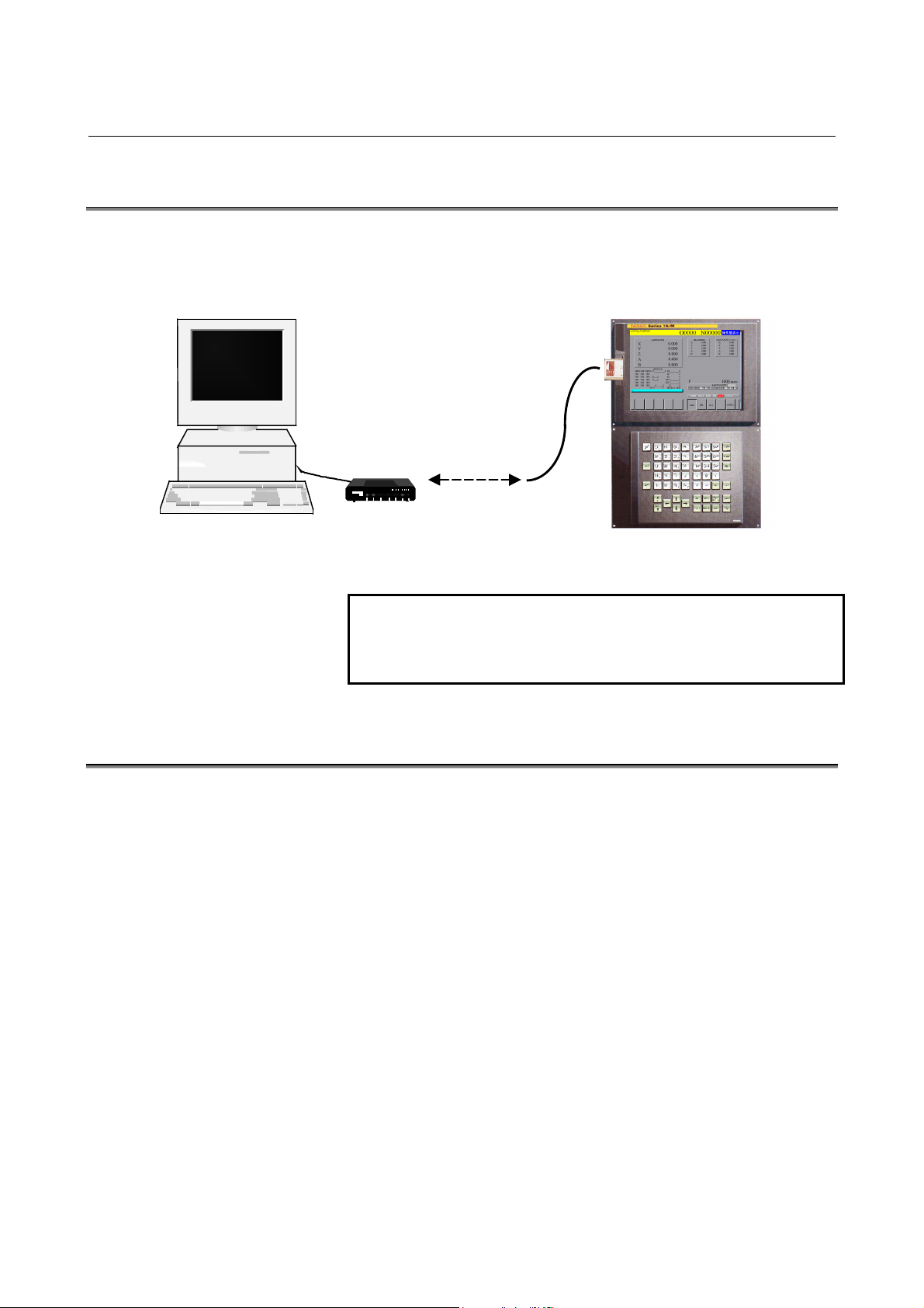
With the remote diagnosis function, CNC data can be transferred
between the FANUC Serie s 15i/16i/18i/21i and a personal computer,
acting as a service terminal, through a telephone line.
Modem Card (Note)
Telephone line
Personal computer
on the host side
1.2 FEATURES
Modem
Series 15i/16i/18i/21i
NOTE
In this manual, modem cards and digital
communication cards are collectively referred to as
modem cards.
(1) By inserting a modem card into the slot on the front of the LCD
unit, a connection can be made to a mobile telephone or
conventional telephone line.
(2) By using a telephone line, the state of a CNC machine tool
installed for from the service center can be m onitored, and its data
can be modified.
(3) Information such as alarm information, parameters, and programs
can be transferred to the service center, so that speedy and timely
maintenance and service are possible.
-2-
Page 12

B-63454EN/01 1. OVERVIEW
1.3 MODELS SUPPORTED
This software runs under Windows95, Windows98, or Windows
NT4.0(*1) on an IBM-PC/AT compatible machine.
*1 This software runs under Windows NT4.0 including
Microsoft Windows NT4.0 Service Pack 3 or above.
1.3.1 About this Software
This software incorporates the following product, the copyright of
which is possessed by Microsoft Corporation of the U.S.A.:
- Microsoft Windows Visual Basic
This software incorporates the following product:
- PDQ COMM
Copyright(c) 1997 Crescent Div. of Progress Software &
Bunka Orient
NOTE
IBM is a registered trademark of International
Business Machines Corporation of the U.S.A..
Windows is a registered trademark of Microsoft
Corporation of the U.S.A..
Visual Basic is a trademark of the Microsoft
Corporation of the U.S.A..
-3-
Page 13

1. OVERVIEW B-63454EN/01
1.4 FUNCTIONS
The software provides the functions listed below.
1.4.1 Download Functions (CNC to Computer)
(See also: Section 4.6)
a. Display
(0) CNC series and edition (21) Number of tool groups
(1) Maintenance information (22) Number of tools
(23) Tool life(2) Printed circuit board
information(*1) (24) Tool life counter
(3) Parameter
(4) Program
(5) Offset
(6) Macro variable
(7) Diagnostic information
(8) Signal state
(9) Machine position
(10) Actual feedrate
(11) Program number (29) Tool information 1
(12) Tool group number (30) Tool information 2
edition (32) Alarm state
(14) Absolute position (33) Ladder title
(15) Skip position (34) Program directory
(16) Servo delay (35) Memory contents
delay (36) Modal data
(18) A/D conversion data (37) Status information
(19) Spindle motor load (38) Alarm history(*2)
(20) Sequence number being
executed
(2 5) Tool length compensation
number 1
(2 6) Tool length compensation
number 2
(27) Cutter compensation
number 1
(28) Cutter compensation
number 2
(31) Tool number(13) Ladder/PMC series and
(dedicated to FANUC)(17) Acceleration/deceleration
(39) Signal state (continuous)
*1, *2 Only for the Series 16i/18i/21i
b. File
For the Series 16i/18i/21i
(0) Maintenance information (4) Operation history
(1) All parameters (5) Alarm history
(2) All programs
(3) One program
-4-
(6) Reception of signals in a
batch
Page 14

B-63454EN/01 1. OVERVIEW
For the Series 15i
(0) Maintenance information
(1) All parameters
(2) All programs (6) System alarm
(3) One program
(4) Operation history/alarm
history
(5) Printed circuit board
information
(7) Reception of signals in a
batch
1.4.2 Upload Function (Computer to CNC)
(See also: Section 4.7)
a. File
(1) All parameters
(2) Program transmission
(3) Program check
b. Input
(1) Parameter
(2) Offset
(3) Macro variable
(4) Signal (PMC/D, K, and others)
(5) Message
1.4.3 Functions related to CNC screen
(See also: Section 4.5.1)
(1) Acquisition of CNC screen data
(2) CNC screen switching
(3) Soft key operation
(4) Page UP/Page DOWN key operation
-5-
Page 15
1. OVERVIEW B-63454EN/01
1.5 EXAMPLES OF EXECUTION
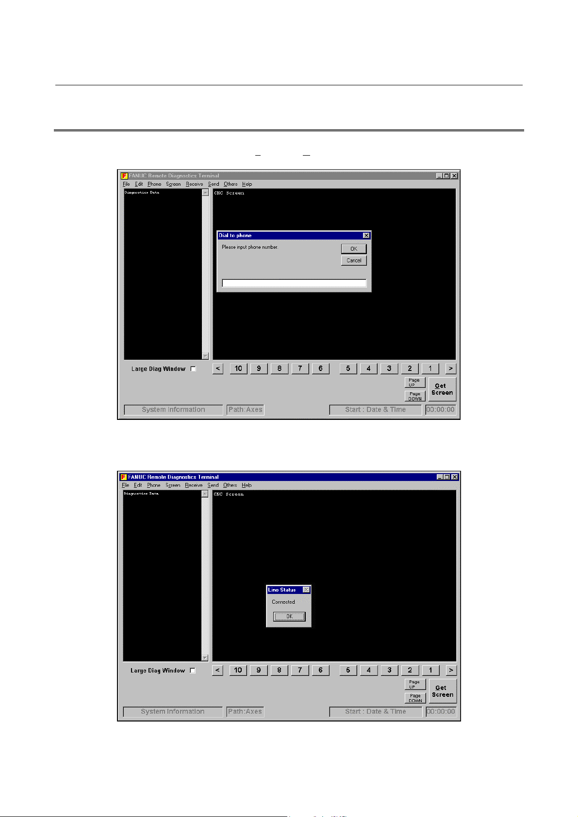
Choose Phone and Dial, then enter the desired telephone number.
0123-45-6789
Clicking the OK button establishes a connection. Once a connection is
established, the following screen appears:
-6-
Page 16
B-63454EN/01 1. OVERVIEW
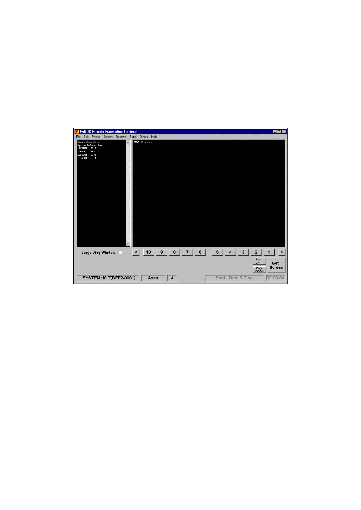
Choose Receive, Display, then (0) CNC Series and Edition. T hen, the
selected data is transferred to the host (in the upper-left part of the
screen). CNC series and edition data is also displayed in the lower-left
part of the screen. With the Series 16i/18i/21i, this information is
received automatically if a telephone line connection is made using a
modem. With the Series 15i, this information is received automa tically
at all times.
-7-
Page 17
1. OVERVIEW B-63454EN/01
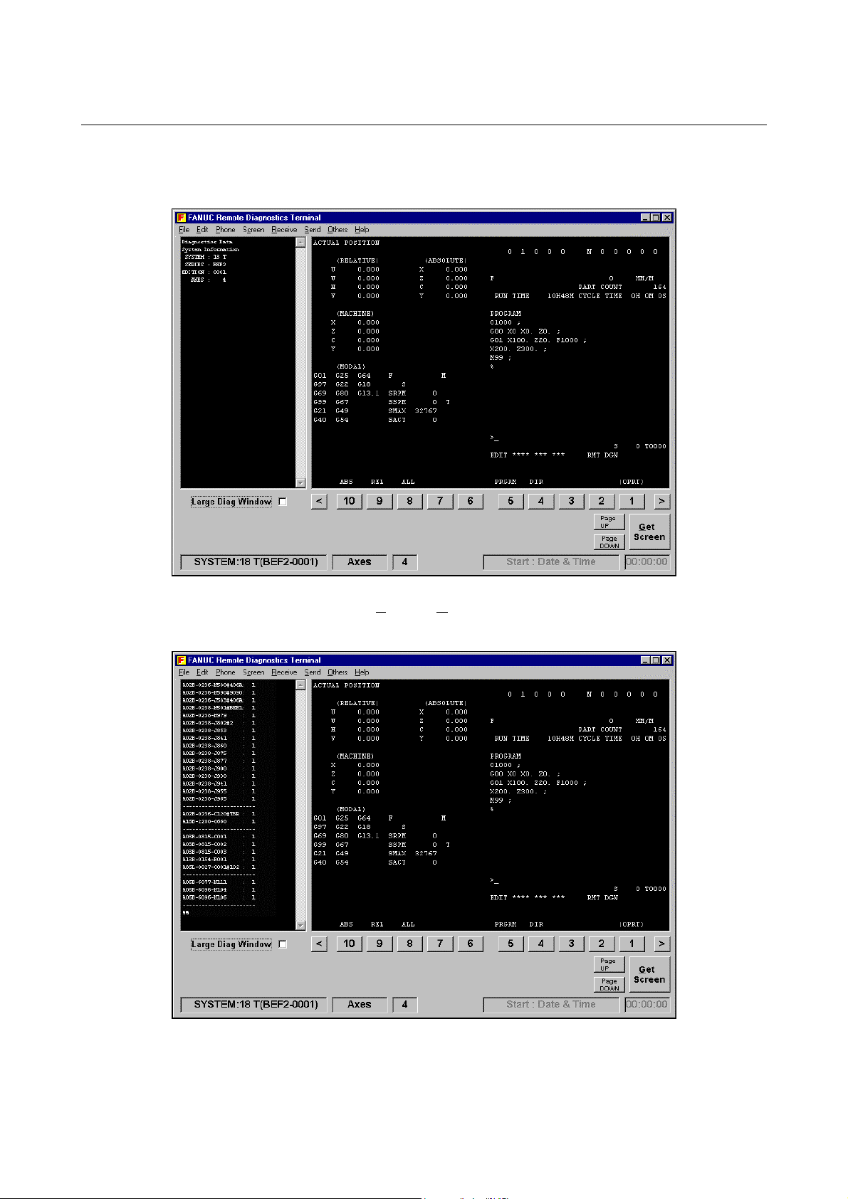
Clicking the GET Screen button transfers the display data for the
current CNC screen.
Choose Receive, D
isplay, then (0) Mainte Info. Then, maintenance
information is received (on the left side of the screen).
-8-
Page 18
B-63454EN/01 1. OVERVIEW
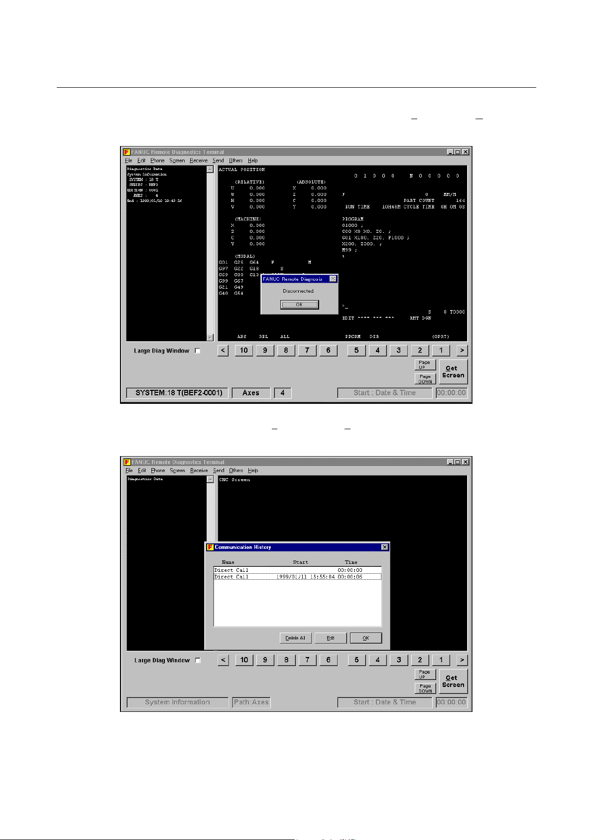
Upon the completion of diagnosis, choose Phone and the Hang to break
the connection.
Choosing Phone and then Phone history allows the user to check the
telephone call history.
-9-
Page 19

2. INSTALLATION PROCEDURE B-63454EN/01
2 INSTALLATION PROCEDURE
-10-
Page 20

B-63454EN/01 2. INSTALLATION PROCEDURE
2.1 CAUTIONS ON INSTALLATION
- At least 6.5MB of free hard disk space is required to install the
host software.
- To upgrade the host software, delete the existing "FANUC
Remote Diagnosis," then install the new version. If a new version
is installed without first deleting the existing version, the new
version may not operate normally.
- When deleting the host software from the personal computer,
select and delete "FANUC Remote Diagnosis" with Add/Remove
Programs on the Control Panel. If the directory and files are
deleted directly, the host software cannot be deleted completely,
leaving the DLL file, OCX file, registry information, and so forth.
- When installing/uninstalling the host software, term inate all other
applications.
- When installing the host software under Windows NT4.0, log on
as the administrator.
-11-
Page 21
2. INSTALLATION PROCEDURE B-63454EN/01
2.2 INSTALLATION
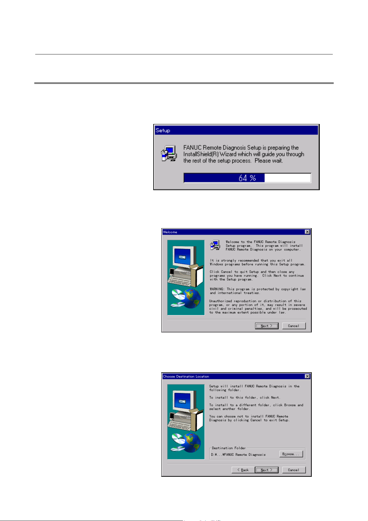
(1) Insert the first floppy disk into the floppy disk drive, and then
execute "Setup.exe" from the floppy disk. Then, the message
shown below appears.
(2) After a short while, the message below appears. Click the Next
button to proceed to the next step.
(3) Click the Next button.
The installation directory can be changed by clicking the Browse
button.
-12-
Page 22
B-63454EN/01 2. INSTALLATION PROCEDURE
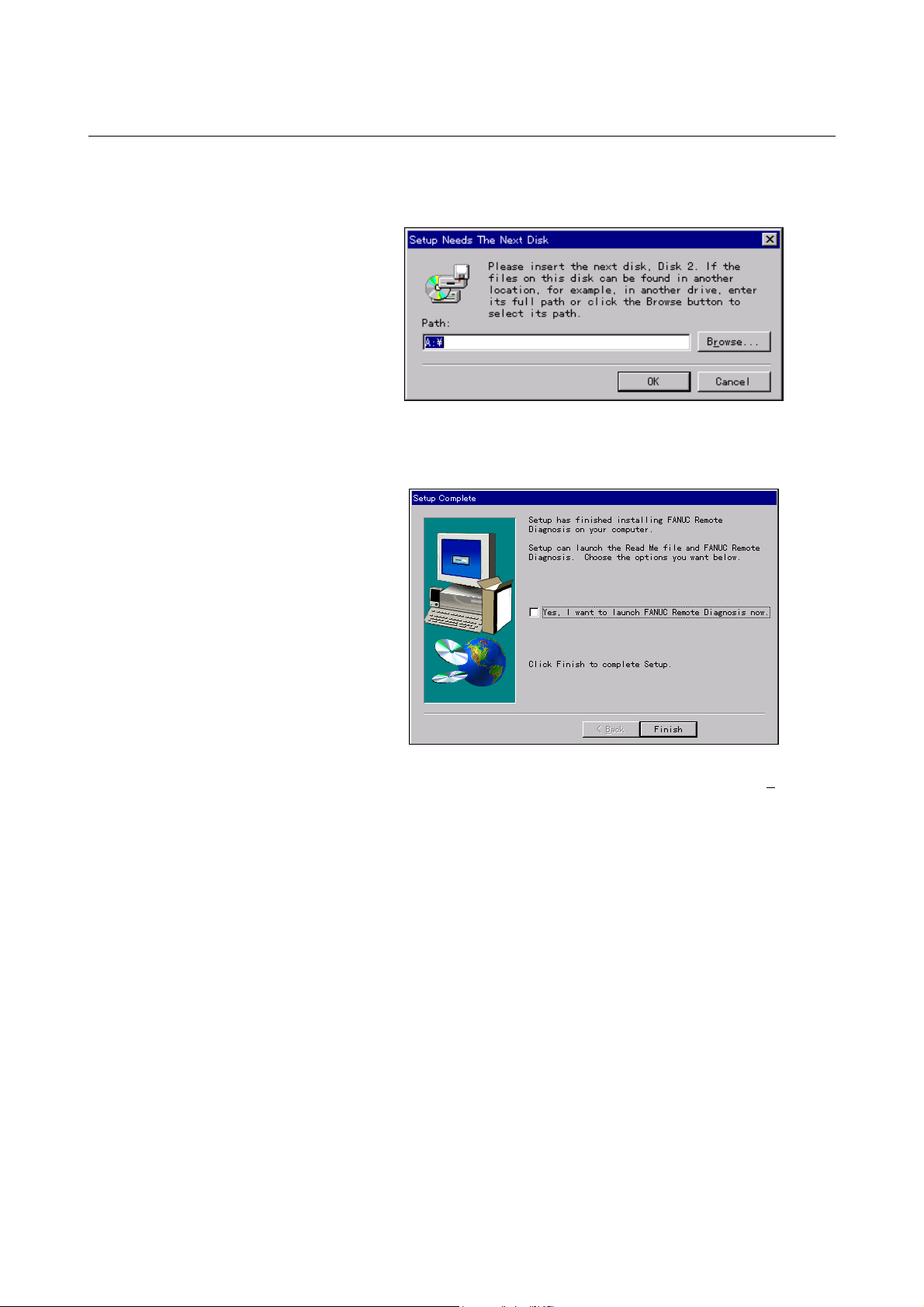
(4) After a short while, the message below appears. I nsert the second
floppy disk into the drive, and then click the OK button.
(5) Upon the normal completion of installation, the message below
appears. Clicking the Finish button terminates the installation.
(6) The host program can be activated by choosing Start, Programs,
and then FANUC Remote Diagnosis from the menu.
-13-
Page 23
2. INSTALLATION PROCEDURE B-63454EN/01
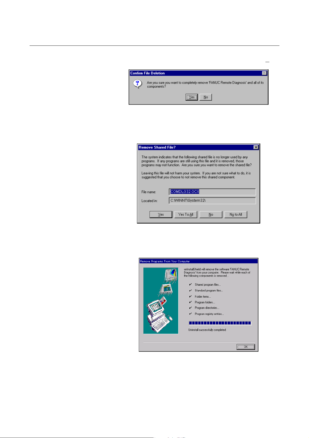
2.3 UNINSTALLATION
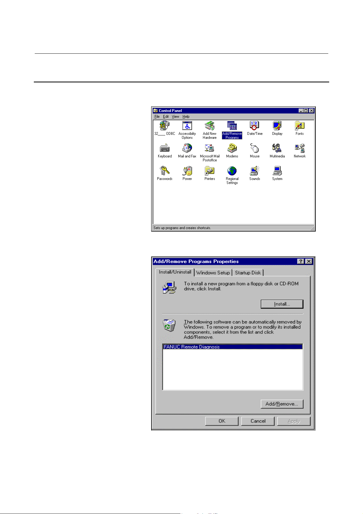
(1) Start Add/Remote Programs in the Control Panel.
(2) Specify deletion of the application "FANUC Remote Diagnosis."
-14-
Page 24
B-63454EN/01 2. INSTALLATION PROCEDURE
(3) The dialog box for deletion confirmation appears. Choose Yes.
(4) The dialog box for confirming that files such as the OCX and DLL
files may be deleted appears. Choose whether to delete these
files.
(5) Upon the completion of application deletion, the message below
appears.
Clicking the OK button terminates the uninstallation work.
-15-
Page 25

3. CONNECTION B-63454EN/01
3 CONNECTION
-16-
Page 26

B-63454EN/01 3. CONNECTION
3.1 CONNECTION BETWEEN T HE CNC AND TELEPHONE LINE
3.1.1 Connecting a Modem Card to the CNC
For the Series 16i/18i/21i
- After turning off the power to the CNC, insert the modem card
into the slot on the front of the CNC’s LCD unit.
- Turn on the power to the CNC. The m odem card is automatically
initialized.
- Whether the modem card has been initialized normally can be
checked using the screen displayed by the following key
operations:
For the Series 15i
Press function key [OFFSET],
If the modem card is initialized normally, "OK" is displayed at the end
of the screen. If the modem card fails to initialize norm ally, the m odem
card itself or a component such as a connector may be faulty.
, and then soft key <MODEM>.
WARNING
It is dangerous to insert a modem card when the
power to the CNC is on. An expected operation may
occur as a result.
NOTE
For an explanation of how to use the modem card,
see the operator’s manuals prov ided wi th the modem
card and mobile telephone. When a mobile
telephone line is used, normal communication may
be impeded by the signal reception status even if the
modem card and its connection are normal.
- After turning off the power to the CNC, insert the modem card
into the slot on the front of the CNC’s LCD unit.
- Turn on the power to the CNC, then set the CNC parameters to
initialize the modem card.
- Whether the modem card has been initialized normally can be
checked on the screen displayed by the following key operations:
Press function key [OFFSET SETTING], soft key <CHAPTER>, and
the soft key <MODEM SETTING>.
If the modem card is initialized normally , the modem type is displayed.
If the modem card is not initialized norm ally, the m odem card itself or a
component such as a connector may be faulty.
For details of the modem setting screen, refer to the relevant section in
"FANUC Series 15i Operator’s Manual (Operation) (B-63324EN)".
-17-
Page 27

3. CONNECTION B-63454EN/01
WARNING
It is dangerous to insert a modem card when the
power to the CNC is on. An expected operation can
occur.
NOTE
For an explanation of how to use the modem card,
see the operator’s manuals prov ided wi th the modem
card and mobile telephone. When a mobile
telephone line is used, normal communication may
be impeded by the signal reception status even if the
modem card and its connection are normal.
3.1.2 Connecting a Modem Via the RS-232-C Interface
Connect an external modem to the reader/punch interface of the CNC.
As the connection cable, a cable used for modem connection (straight
type) is used. For details, refer to the manual for the modem.
For making a connection, CNC parameter setting is required. The
parameter numbers for setting vary between the Series 15i and the
Series 16i/18i/21i.
(See also: Section 3.3.2)
NOTE
1 T he RS-232-C serial port of the CNC has +5 V and
+24 V outputs. Pin 25 of the reader/punch interface
relay connector outputs +24 V. Usually, modems do
not require these power supplies. Ensur e that these
power supplies are not connected to the modem by
the connection cable. Ensure also that even if these
power supplies are connected to the modem, modem
operation is not adversely affected. If these power
supplies are connected to a modem without sufficient
care, the modem may be damaged.
2 An external modem connected to the CNC must be
set as described in the examples below when the
power is turned on. By referring to the specifications
of the modem being used, set the modem, for
example, with a personal computer as described
below.
Setting example 1 (for the Series 16i/18i/21i)
An external modem, when turned on, must be set as following:
- Automatic termination enabled
-18-
Page 28

B-63454EN/01 3. CONNECTION
- CD signal turned on at all times
- ER signal turned on at all times
- Data flow control XON/XOFF
- Automatic transmission speed adjustment enabled (to allow
automatic adjustment for connection at a maximum allowable
speed)
- Command echo not used
- Result code not used
Example of external modem setting
In this example, the use of the following modem is assumed for
command settings:
Panasonic: TO-BXF56K
Connect the modem to the personal computer, then start the terminal
software.
→ For connection between the personal computer and modem, refer
to the manuals provided with the personal computer and modem.
→ Windows is delivered with terminal software named Hyper
Terminal.
Using the terminal software, send the following commands, in the
listed order, to the modem:
Command Description
AT&F : Returns the settings to their initial values.
ATS0=3 : Sets the S register (to ring three times for automatic
AT&C0 : Turns on the CD signal at all times.
AT&D0 : Turns on the ER signal at all times.
AT&K4 : Applies XON/XOFF flow control.
AT&Y0 : Reads the settings of profile 0 when the power is on.
ATN1 : Enables automatic mode (for automatic transmission
ATE0 : Does not use command echo.
ATQ1 : Does not use result code.
AT&W0 : Saves the settings as profile 0.
In addition to the above, CNC parameter setting is required. See
Appendix B.
Setting example 2 (for the Series 15i)
- Automatic termination enabled
- Error correction connection display not provided
- Fixed terminal speed mode enabled
- CD signal turned on at all times
- ER signal turned on at all times
- Send data flow control XON/XOFF
- Receive data software flow XON/XOFF
- Receive data hardware flow not used
- Transmission speed specification (for setting of a transmission
speed on the CNC)
termination).
speed determination).
-19-
Page 29

3. CONNECTION B-63454EN/01
- Command echo not used
- Local echo not used
- Result code not used
Example of external modem setting
In this example, the use of the following modem is assumed for
command settings:
Omron: ME3314B
Connect the modem to the personal computer, then start the terminal
software. (For details of the connection between the personal computer
and modem, refer to the manuals provided with the personal computer
and modem.)
Send the commands below, in the listed order, to the modem. It is
assumed that the transmission speed on the CNC side is 9600 bps.
Command Description
AT&F : Returns the settings to the initial setting values.
ATS0=3 : Sets the S register (to ring three times for automatic
termination).
AT&A0 : Provides no error correction connection display.
AT&B1 : Enables fixed terminal speed mode.
AT&C0 : Turns on the CD signal at all times.
AT&D0 : Turns on the ER signal at all times.
AT&H2 : Send data flow control XON/XOFF.
AT&I1 : Receive data software flow XON/XOFF
AT&R1 : Provides no receive data software flow.
AT&N6 : Transmission speed specification (9600 bps)
AT&Y0 : Reads the settings of profile 0 when the power is on
ATE0 : Does not use command echo.
ATF1 : Does not use local echo.
ATQ1 : Does not use result code.
AT&W0 : Saves the settings as profile 0.
3.1.3 Making a Direct Connection Via the RS-232-C Interface
Remote diagnosis can be performed without using a telephone line.
Connect the reader/punch interface of the CNC directly to the personal
computer. As the connection cable, a cable for I/O device connection
(cross-type) is used.
For making a connection, CNC parameter setting is required. The
parameter numbers for setting vary between the Series 15i and the
Series 16i/18i/21i.
(See also: Section 3.3.2)
-20-
Page 30

B-63454EN/01 3. CONNECTION
3.2 CONNECTION BETWEEN THE PERSONAL COMPUTER
AND TELEPHONE LINE
Make a connection as explained in the manuals provided with the
personal computer and modem.
-21-
Page 31

3. CONNECTION B-63454EN/01
3.3 CNC SETTING
3.3.1 Connecting a Modem Card to the CNC
For the Series 16i/18i/21i
Basically, no parameters need to be set. For transm ission at a baud rate
other than 9600 bps, make the following settings:
- Bit 6 (MCB) of No. 0201 = 1
- No. 0203 = 1 to 12
(For details, see Appendix B.)
The optional reader/punch interface is not required.
NOTE
When a mobile telephone is used, the
communication baud rate is 9600 bps.
For the Series 15i
Make the following parameter settings:
- Bit 2 (ISP) of No. 0000 = 1
- Bit 3 (NCR) of No. 0000 = 1
- Bit 4 (EIA) of No. 0000 = 0
- No. 0020 through No. 0023 = 12
- No. 0040 = 17
- No. 5004 = 1 to 6
Set parameter No. 5110 through No. 5162 according to the setting of
parameter No. 5004. Set 3 as the I/O device specification number in
parameters No. 5110 through No. 5162.
Upon the completion of communication parameter setting, set the
parameter below. When the parameter below is set to 1, the CNC
acquires the communication parameters, and initializes and opens the
port. Set the parameter to 0 once remote diagnosis ends.
- Bit 6 (RDN) of No. 0000 = 1
The optional reader/punch interface is not required.
3.3.2 Making a Connection Via the RS-232-C Interface:
Using an External Modem or Making a Direct Connection
For the Series 16i/18i/21i
Make the following parameter settings:
- Bit 0 (SB2) of No. 0201 = 0
- Bit 1 (ASC) of No. 0201 = 1
- Bit 2 (NCR) of No. 0201 = 1
- No. 0203 = 1 to 12
(For details, see Appendix B.)
-22-
Page 32

B-63454EN/01 3. CONNECTION
When starting remote diagnosis, set bit 0 (RDG) of param eter No. 0002
to 1. Upon the completion of remote diagnosis, set bit 0 of parameter
No. 0002 to 0.
When bit 0 of No. 0002 = 1, the line status can be check ed on the CNC
screen by pressing the following keys in this order:
Function key [MESSAGE], Soft key
<RMTDGN>
When the CNC is normal, the following message appears, indicating
that the CNC is awaiting data:
LINE STATUS : DATA WAITING
If the CNC experiences a fault, the following message appears:
LINE STATUS : LINE ERROR
Set bit 0 of parameter No. 0002 to 0 once, then set the same bit to 1. I f
the error message still appears, turn off the power to the CNC and
personal computer, then back on again, or check the connections.
, and Soft key
For the Series 15i
NOTE
The optional reader/punch interface is required.
Make the following parameter settings:
- Bit 2 (ISP) of No. 0000 = 1
- Bit 3 (NCR) of No. 0000 = 1
- Bit 4 (EIA) of No. 0000 = 0
- No. 0020 through 0023 = 12
- No. 0040 = 1, 2, or 3
Set parameter No. 5001 through No. 5003 and No. 5110 through No.
5162 according to the setting of parameter No. 0040.
Set 3 as the I/O device specification number in parameter No. 5110
through No. 5162.
Upon the completion of communication parameter setting, set the
parameter below. When the parameter below is set to 1, the CNC
acquires the communication parameters, and initializes and opens the
port. Set the parameter to 0 upon the completion of remote diagnosis.
- Bit 6 (RDN) of No. 0000 = 1
NOTE
The optional reader/punch interface is not required.
-23-
Page 33

3. CONNECTION B-63454EN/01
3.4 SETTING THE PERSONAL COMPUTER
The user must choose Others and Setting comm for communicationrelated setting.
For the Series 16i/18i/21i
For the Series 15i
Set each item according to the parameters for the personal computer,
telephone line, and CNC.
(See also: Section 4.9.1)
Set Data Bit, Parity Bit, and Flow Control as follows:
Data Bit = 8, Parity Bit = None, Flow Control = Xon/Xoff
Set the other items according to the parameters for the personal
computer, telephone line, and CNC.
(See also: Section 4.9.1)
-24-
Page 34

B-63454EN/01 3. CONNECTION
3.5 LINE CONNECTION/DISCONNECTION
3.5.1 Line Connection (when Usi ng a Modem Card)
a) Making a connection for the first time
Choose Phone and then D
appears:
Enter the desired telephone number, then click the OK button to
establish the connection.
ial. Then, the following window
b) Making a connection to the same destination more than once
The user can make a connection to a destination by other means
very easily provided that destination is registered in the list of
destinations.
(See also: Section 4.4)
NOTE
The type of telephone line needs to be entered in the
communication settings.
(See also: Section 4.9.1)
3.5.2 Line Disconnection (w hen Usi ng a Modem Card)
Choose Phone and then Hang. The connection is broken.
-25-
Page 35

3. CONNECTION B-63454EN/01
3.5.3 Line Connection/Disconnection (when Connecting an
External Modem Via the RS-232-C Interface)
For the Series 16i/18i/21i
A connection can be made/broken in the same way as when a modem
card is used.
(See also: Section 3.5.1)
(See also: Section 3.5.2)
Before making a connection, set bit 0 of CNC parameter No. 0002 to 1.
After line disconnection, set bit 0 of parameter No. 0002 to 0.
(See also: Section 3.3.2)
For the Series 15i
A connection can be made/broken in the same way as when a line is
connected using a modem card.
(See also: Section 3.5.1)
(See also: Section 3.5.2)
3.5.4 Line Connection/Disconnection (when Making a Direct
Connection Via the RS-232-C Interface)
For the Series 16i/18i/21i
Operation from the host software is not required. To make a
connection, set bit 0 of CNC parameter No. 0002 to 1. To break the
connection, set bit 0 of parameter No. 0002 to 0.
(See also: Section 3.3.2)
For the Series 15i
In communication setting, set RS-232-C for Device, then choose Phone
and the Dial. The line is connected.
-26-
Page 36

B-63454EN/01 3. CONNECTION
3.6 ACCESS RIGHT
3.6.1 About Access Right
To access a CNC for which a password is set to protect the CNC
machine tool information, the access right must be acquired using the
password. Otherwise, the CNC information cannot be acquired.
3.6.2 Password Setting for the CNC
For an explanation of how to set a CNC password, see Appendix B.
For the Series 16i/18i/21i
Parameter No. 211 through No. 213, and No. 221 through No. 223
For the Series 15i
Parameter No. 0042 through No. 0047
3.6.3 Password Registration on the Host Software Side
Before making a connection, register a password by using the setting
dialog box (Communication List Properties) for the communication
destination. Enter an eight-digit password. For an explanation of
dialog box display operation and connection-related operation after
password input, see Section 4.4.3.
Enter passwords.
When a communication destination is registered, passwords are
registered together with the name and telephone number of the
communication destination.
Subsequently, when choosing, and connecting to, a communication
destination displayed on the Phone menu, acquire the access right by
using the password registered here.
-27-
Page 37

3. CONNECTION B-63454EN/01
3.6.4 About Passwords
Password 1 : Password 1: Enter a password for all remote diagnosis
function services.
If an entered password is unacceptable, the following
dialog box is displayed when an attem pt is m ade to m ak e
a connection, and the attempt to connect to the CNC is
rejected:
Password 2 : Enter a password for acquiring the right to access
programs.
If an entered password is unacceptable, the following
dialog box appears when an attempt is made to access a
program, and the attempt to access the program is
rejected:
Password 3 : Enter a password for acquiring the right to access
parameter information.
If an entered password is unacceptable, the following
dialog box appears when an attempt is made to access a
parameter, and the attempt to access the parameter is
rejected:
-28-
Page 38

B-63454EN/01 4. OPERATION
4 OPERATION
-29-
Page 39

4. OPERATION B-63454EN/01
4.1 FUNCTION OVERVIEW
4.1.1 Screen Configuration
When the remote diagnosis host software is started, the following
screen appears:
C
AB
E
F
H
G
A. Diagnosis data display screen : This area displays diagnosis data received from the CNC.
B. CNC screen data display : This area displays screen data received from the C NC. On ly character
data is displayed. Graphics are not displayed. Attributes such as color,
reverse video, and blinking are not transferred.
C. Pull-down menu : Various operation menus are provided.
D. Get Screen button : This button is used to acquire CNC screen data (character data).
E. S oft keys : Sele cti ng a s oft key ha s th e sa me ef fec t as pre ssi ng a s oft key o n th e
CNC.
F. Page UP/Page DOWN : Selecting Page UP/Page DOWN has the same effect as pressing the
MDI key PAGE UP/PAGE DOWN on the CNC.
G. Large Diag Window : Checking the check box enlarges the display of area A.
H. Start:Date&Time : Choosing this item displays the start date and time of communication
and the duration of communication when a modem is used.
D
−30−
Page 40

B-63454EN/01 4. OPERATION
4.1.2 Pull-Down Menu
The menus on the screen are configured as described below.
For the Series 16i/18i/21i
File Edit Phone Screen Receive Send Others Help
File Print
US version >
Japanese version >
eXit
Edit Copy
Copy to file(I)
select Range
Find
Find Next
Mark
Jump
Select all
Erase diag data
Phone Phone List
Dial
Hang
comm List
Phone history
Screen ( 0) POSITION >
( 1) PROGRAM >
( 2) OFFSET >
( 3) SYSTEM >
( 4) MESSAGE >
( 5) CUSTOM >
Prints the currently displayed host software screen data.
Switches the menu language and screen format.
Quits the host software.
Performs operations on the diagnosis data display screen.
Performs operations associated with the connection with the CNC.
Switches the screen display from one CNC screen to another
according to the menu selection.
Receive Display
File > ( 0) Mainte Info
Send Input > Selects the data to be sent to the CNC.
File >
Selects the data to be received from the CNC.
( 1) All Parameters
( 2) All Program
( 3) One Program
( 4) Operation History
( 5) Alarm History
( 6) Receive Signals
-31-
Page 41

4. OPERATION B-63454EN/01
Others Setting comm
Folder setting
Select Path >
AutoGetScreen >
MDIkey >
Keyfree(Q)
CNC MDI Key(C) >
Help Version info
For the Series 15i
File Edit Phone Screen Receive Send Others Help
File Print
US version >
Japanese version >
eXit
Edit Copy
Copy to file(I)
select Range
Find
Find Next
Mark
Jump
Select all
Erase diag data
Makes settings related to the serial port.
Makes directory settings such as file input/output.
Chooses a CNC system.
Chooses whether to transfer screen data automatically.
To be chosen when MDI key input is performed from the personal computer
To be chosen when soft key operation is disabled during operation
Chooses whether to disable MDI operation on the CNC.
Displays the version of the host software.
Prints the currently displayed host software screen data.
Switches the menu language and screen format.
Quits the host software.
Performs operations on the diagnosis data display screen.
Phone Phone List
Dial
Hang
comm List
Phone history
Screen ( 0) POSITION >
( 1) PROGRAM >
( 2) OFFSET >
( 3) SYSTEM >
( 4) MESSAGE >
Receive Display
File > ( 0) Mainte Info
Performs operations associated with the connection with the CNC.
Switches the screen display from one CNC screen to another
according to the menu selection.
Selects the data to be received from the CNC.
( 1) All Parameters
( 2) All Program
( 3) One Program
( 4) Operation / Alarm History
( 5) Circuit Info
( 6) System Alarm
( 7) Receive Signals
−32−
Page 42

B-63454EN/01 4. OPERATION
Send Input >
File >
Others Setting comm
Folder setting
Select Path >
AutoGetScreen >
MDIkey >
Keyfree(Q)
CNC MDI Key(C)>
Help Version info
4.1.3 Other Buttons
Selects the data to be sent to the CNC.
Makes settings related to the serial port.
Makes directory settings such as file input/output.
Not used
Chooses whether to transfer screen data automatically.
Not used
To be chosen when soft key operation is disabled during operation
Not used
Displays the version of the host software.
(a) Get Screen button
This button is used to acquire CNC screen data (character data).
(b) Soft keys
Choosing a soft key has the same effect as pressing a soft key on
the CNC.
(c) Page UP and Page DOWN keys
Choosing these keys has the same effect as pressing the MDI key s
PAGE UP and PAGE DOWN on the CNC.
These buttons are used in combination with each other.
(See also: Section 4.5)
-33-
Page 43

4. OPERATION B-63454EN/01
4.2 FILE MENU
4.2.1 Print
The user can print the data currently displayed on the host software.
NOTE
The printer to be used needs to be set in W indows
beforehand.
4.2.2 US version/Japanese version
The user can select the language used, for example, for the host
software menus.
For the Series 16i/18i/21i
At the same time, the user must choose the type of CNC screen data
display and the number of soft keys.
For the Series 15i
4.2.3 Exit
US version →
80 characters wide : Display in English/80 characters wide/10
soft keys
40 characters wide : Display in English/40 characters wide/5 soft
keys
Japanese version →
80 characters wide : Display in Japanese/80 characters wide/10
soft keys
40 characters wide : Display in Japanese/40 characters wide/5
soft keys
US version : Display in English
Japanese version : Display in Japanese
This menu item quits this software (remote diagnosis host software).
−34−
Page 44

B-63454EN/01 4. OPERATION
4.3 EDIT MENU
4.3.1 Copy
This menu item copies the selected data to the Windows clipboard.
Right-clicking a selected range of data has the same effect.
4.3.2 Copy to file(I)
Selected data can be output to a file. When this menu item is chosen,
the file name selection dialog box appears. When a file name is chosen
in the dialog box, the selected data is output as text data to that file.
4.3.3 select Range
This menu item moves the cursor to the diagnosis data display screen.
4.3.4 Find, Find Next
4.3.5 Mark, Jump
4.3.6 Select all
4.3.7 Erase diag data
The user can search for data displayed on the diagnosis data display
screen.
The jump function enables the user to move the cursor to a desired
position on the diagnosis data display screen. The mark function is
used to set a jump destination. When the m ark function is executed, the
point where the cursor is currently positioned is memorized as a mark
position, and the last specified position becomes a jump destination.
This menu item selects all data on the diagnosis data display screen.
This menu item deletes the data on the diagnosis data display screen.
-35-
Page 45

4. OPERATION B-63454EN/01
4.4 PHONE MENU
4.4.1 Dial
When this menu item is chosen, the following window appears:
Enter the desired telephone number, then click the OK button to start
the connection of the telephone line.
NOTE
The type of telephone line must be entered in the
communication settings.
(See also: Section 4.9.1)
4.4.2 Hang
When this menu item is chosen after the end of remote diagnosis, the
connection is broken.
4.4.3 Phone List, comm List
This function enables a connection to easily be made to a
communication destination registered in the list of communication
destinations. First, a desired communication destination must be
registered in the phone list by using comm List.
(1) When comm List is chosen, the following dialog box appears:
−36−
Page 46

B-63454EN/01 4. OPERATION
(2) To set a new communication destination, choose the New button
with the mouse. To modify an existing communication
destination, choose the communication destination with the
mouse, and the click the Properties button. Then, the following
communication destination setting dialog box appears.
(3) Enter desired information. If a password has been set for the CNC,
enter the password in the password field. Then, click the OK
button.
The screen display returns to the communication destination
setting menu of (1) above. Then, click the Save button to save the
setting, and then click the Exit button.
(4) The communication destination names registered in the list of
communication destinations are displayed in Phone List of Phone.
By choosing from the list, a connection can be made easily.
-37-
Page 47

4. OPERATION B-63454EN/01
Phone list
4.4.4 Phone history
NOTE
Up to ten communication destinations are displayed
on the menu. The order of communication
destinations can be changed by clicking the
UP/DOWN button in co mm List. An item for which
Add Menu List is not checked in the communication
destination setting dialog box is not added to Phone
List.
The history of communication can be checked.
The Name field displays the name of a communication destination if a
connection is made using the list of communication destinations. If a
connection is made using Dial, "Direct Call" is indicated.
−38−
Page 48

B-63454EN/01 4. OPERATION
4.5 SCREEN SWITCHING
The user can switch from one CNC screen to another. The Get Screen
button is used to transfer the information of a switched screen. (See
also: Section 4.1.3)
For the Series 16i/18i/21i
The items indicated below are displayed. Symbols [i], [M], and [T] on
the menu represent those functions dedicated to the i series, M series,
and T series, respectively.
POSITION
- ABSOLUTE - HANDLE INTERRUPT
- RELATIVE - OPERATING MONITOR
- ALL - [i] C Executor
PROGRAM
- MDI PROGRAM - C.A.P.
- PROGRAM - SCHEDULE
- LIBRARY - CYCLE TIME
- CURRENT BLOCK
-NEXT BLOCK
- PROGRAM CHECK - [i] JOG
- PROGRAM RESTART - [i] C Executor
- FLOPPY DIRECTORY
OFFSET
- OFFSET (GEOM,WEAR) -
- SETTING PARAMETER [T] Y-AXIS OFFSET
- WORK COORDINATE -
- MACRO VARIABLE [T] TOOL FORM
- MENU - [iM] C Executor
- OPERATOR’S PANEL [T] BARRIER
- TOOL LIFE - [T] B-AXIS OFFSET
-
[M] CHOPPING PARAMETER - [iT] 2ND OFFSET GEOMETRY
[T] WORK SHIFT
-[i] DATA SERVER
DIRECTORY
[M] TOOL LENGTH MES.-B
[iM] INTERFERENCE CHECK
- [iT] C Executor
-39-
Page 49

4. OPERATION B-63454EN/01
SYSTEM
- PARAMETER
- DIAGNOSE
-PMC
- [I] DATA SERVER
MAINTENANCE
- [I] DATA SERVER MODE
STORAGE
- SYSTEM - [I] VGA COLOR SETTING
-MEMORY
- PITCH ERROR
- SERVO SETTING
- SPINDLE SETTING
-
[I] PERIODICAL
MAINTENANCE DISP
- [I] MAINTENANCE
INFORMATION DISP
- [i] C-SERV - [I] PMM
- M-CODE GRP SETTING
- OPERATION HISTORY
-
[I] PROGRAM TAPE
MEMORY CHECK DISP
- ALL I/O - [I] FSSB SETTING DISPLAY
- [I] C-OPER - [I] C Executor
- [I] DATA S ERVER SETTING
MESSAGE
-ALARM -NETWORK MESSAGE
- EXTERNAL MESSAGE
- ALARM HISTORY
-
OPERATOR’S MESSAGE - [I] FACTOLINK
-
REMOTE DIAGNOSTICS - [I] C Executor
-
EXTERNAL/OPERATOR’S
MESSAGE HISTORY
- [I] DATA SERVER
MESSAGE
CUSTOM
- LANGUAGE - CUSTOM 2
- CUSTOM 1 - CUSTOM 3
For the Series 15i
NOTE
If a screen that cannot be displayed while the CNC is
being diagnosed is chosen, the screen cannot be
switched correctly.
The items below are displayed.
POSITION
- OVER ALL - ABSOLUTE
- RELATIVE - MACHINE
PROGRAM
- PROGRAM TEXT - ACTUAL BLOCK
-
PROGRAM DIRECTORY - OPERATING MONITOR
- PROGRAM CHECK - POSITION DATA
- LAST BLOCK
OFFSET
- TOOL OFFSET - FLOPPY DIRECTORY
- WORK ZERO OFFSET - MEMORY CARD
-
SETTING PARAMETER
-TIMER
COM. SETTING (RS232C,
-
RS422)
SERVICE
-40-
Page 50

B-63454EN/01 4. OPERATION
- PARAMETER - SYSTEM CONFIGURATION
-PMC- PITCH ERROR
COMPENSATION
- SERVO SETTING
- DIAGNOSIS - HPCC
-
DI/DO SIGNAL MONITOR - FSSB SETTING
-
PERIODICAL MAINTENANCE - CONTENTS OF MEMORY
-
MAINTENANCE
INFORMATION
MESSAGE
-ALARM
NOTE
If a screen that cannot be displayed while the CNC is
being diagnosed is chosen, the screen cannot be
switched correctly.
4.5.1 Using the Screen Swit ching Function
The screen of the CNC under remote diagnosis can be switched by
using the screen switching menu, the soft keys on the host software,
and the Page UP/Page DOWN keys. Note that switching switches only,
the CNC screen. Clicking the Get Screen button can transfer the CNC
screen information currently being displayed to the host software.
Thus, the user can view a switched screen on the host software as in the
case of direct CNC operation.
NOTE
1 Information such as coordinates and signal states
cannot be displayed on a real-time basis.
2 Only character data is displayed on the host software.
3 Character attributes (such as color, reverse video,
and the blinking state) cannot be displayed.
(1) A command based on screen selection/page key/soft key
operation is issued with the host software.
Screen selection
Page keys
Soft keys
Personal computer on
the host side
Series 15i/16i/18i/21i
-41-
Page 51

4. OPERATION B-63454EN/01
(2) When the command is received, the CNC screen is switched.
(3) CNC screen information is transferred to the host software by
using the Get Screen button.
GET SCREEN button
Example of screen switching
Display before screen switching
Supplement : By choosing Others and AutoGetScreen, screen
information can also be transferred automatically after
screen switching.
-42-
Page 52

B-63454EN/01 4. OPERATION
Choose Screen, (3) SYSTEM, and then (4) SYSTEM, and then click
the Get Screen button. The screen display changes to the following:
-43-
Page 53

4. OPERATION B-63454EN/01
4.6 RECEIVE DATA
4.6.1 Receive (Display)
The following data can be displayed by choosing Receive and then
Display from the menu.
(0) CNC series and edition (14) Absolute position (27) Cutter compensation number 1
(1) Maintenance information (15) Skip position (28) Cutter com pensation nu mber 2
(16) Servo delay (29) Tool information 1(2) Printed circuit board
information(*1) (17) Acceleration/deceleration delay (30) Tool information 2
(3) Parameter (18) A/D conversion data(*2) (31) Tool number
(4) Program (19) Spindle motor load (32) Alarm state
(5) Offset (33) Ladder title
(6) Macro variable
(7) Diagnostic information (21) Number of tool groups
(8) Signal state (22) Number of tools
(9) Machine position (23) Tool life (36) Modal data
(10) Actual feedrate (24) Tool life counter (37) Status information
(11) Program number (38) Alarm history(*3)
(12) Tool group number
(13) Ladder/PMC series and
edition
(20) Sequence number being
executed (34) Program directory
(35) Memory contents (dedicated to
FANUC)
(25) Tool length compensation
number 1 (39) Signal state (continuous)
(26) Tool length compensation
number 2
*1 Only for the Series 16i/18i/21i
*2 Not usable with the Series 16i/18i/21i
*3 Only for the Series 16i/18i/21i
WARNING
The function for receiving (35) memory contents is
dedicated to FANUC. Using this function incorrectly
can result in an unexpected operation.
NOTE
1 The function f or receiving (18) A/D conversion data
cannot be used with the Series 16i/18i/21i.
2 Data such as actual feedrate and the signal state
cannot be taken in on a real-time basis.
-44-
Page 54

B-63454EN/01 4. OPERATION
Supplement:
(5) Offset
In addition to an offset number, an offset ty pe must be set. Set an
offset type as described below
M series (machining center)
Tool radius Tool length
Wear 0 2
Figure 1 3
(Supplement) Set 0 when there is no tool radius/tool length
distinction and no wear/figure distinction.
T series (lathe)
X-axis Z-axis Tool nose
radius
Wear 0 2 4 6 8
Figure 1 3 5 7 9
Virtual
tool nose
Y-axis
(34) Program directory
For the Series 16i/18i/21i
After a program number, a comm ent and the num ber of characters
used are displayed. If no comment is added to a program, control
in/control out codes are displayed.
As the number of characters used, and the number of characters
indicated in a CNC program directory display is displayed.
<Example of display>
O2114(MAIN PROGRAM)360
O2119(SUB1)120
O2147()60
For the Series 15i
In a program directory, only the program numbers are displayed.
(39) Signal state (continuous)
The state of a specified one-byte PMC signal is automatically and
continuously read and displayed. So, the user can use this
function to check whether a signal is changing. Because of
transmission speed limitations, however, the state of a signal
cannot be displayed completely on a real-time basis.
-45-
Page 55

4. OPERATION B-63454EN/01
4.6.2 Receive (File)
The data files listed below can be received by choosing Receive and
File from the menu.
(See also: Section 4.8.2)
For the Series 16i/18i/21i
(0) Maintenance information
(1) All parameters
(2) All programs
(3) One program
(4) Operation history
(5) Alarm history
(6) Reception of signals in a batch
Supplement:
The function for receiving (4) Operation history receives a CNC
operation history recorded on the CNC, as a data file. (The same data
as that output to the CNC can be acquired.) For details of the operation
history, including the format of operation history data, refer to
"FANUC Series 16i/18i/21i Maintenance Manual (B-63005EN)".
For the Series 15i
(0) Maintenance information
(1) All parameters
(2) All programs
(3) One program
(4) Operation history/alarm history
(5) Printed circuit board information
(6) System alarm
(7) Reception of signals in a batch
NOTE
Before maintenance information can be received, the
CNC must be placed in edit mode (with the Series 15i
only).
-46-
Page 56

B-63454EN/01 4. OPERATION
4.7 SEND DATA
4.7.1 Send (Input)
The following data can be entered by choosing Send and Input.
(1) Parameter (4) Signal
(2) Offset (5) Message
(3) Macro variable
Supplement:
(2) Offset
In addition to an offset number, an offset type needs to be set. Set
an offset type as described below.
M series (machining center)
Tool radius Tool length
Wear 0 2
Figure 1 3
(Supplement) Set 0 when there is no tool radius/tool length
distinction and no wear/figure distinction.
T series (lathe)
X-axis Z-axis Tool nose
radius
Wear 0 2 4 6 8
Figure 1 3 5 7 9
Virtual
tool nose
Y-axis
(5) Message
With this function, a message entered through the host computer
can be displayed on the CNC screen. When a message is sent, the
CNC screen is automatically switched to the remote diagnosis
screen to display the sent message. Only alphanum eric characters
can be used.
-47-
Page 57

4. OPERATION B-63454EN/01
4.7.2 Send (File)
The data described below can be sent by choosing Send and then File.
(See also: Section 4.8.2)
(1) All parameters
(2) Program transmission
(3) Program check
NOTE
1 Bef ore parameters can be entered or all parameters
can be sent, the CNC must be placed in the
emergency stop state.
2 Bef ore programs can be sent or checked, the CNC
must be placed in edit mode.
3 For the Series 16i/18i/21i
If the file size of data to be sent or checked exceeds a
limit described below, the data cannot be sent or
checked. If a file exceeding a size described bel ow is
sent, the remote diagnosis software and CNC will
hang.
Parameter: 1500 bytes
Program: 400 bytes
-48-
Page 58

B-63454EN/01 4. OPERATION
4.8 OTHER MENUS
4.8.1 Setting comm
The following dialog box appears.
For the Series 16i/18i/21i
For the Series 15i
Set each item as described below.
Port : Set a serial port number of the personal computer.
BPS : Set the same transmission speed as that set on the
CNC.
DATA Bit : Set 8.
Stop Bit : Set 1.
Parity Bit : Set None when using a modem line.
Flow Control : Set Xon/Xoff when making a direct connection to the
CNC without using a modem.
Tone/Pulse : Specify the type of telephone line to be connected to
the host.
Device : Set Modem when using a modem line.
Set RS-232-C when making a direct connection to the
CNC without using a modem.
Note, however, that even if RS-232-C is set, the value
is not held. Instead, the setting in the dialog box
returns to Modem.
Port : Set a serial port number of the personal computer.
BPS : Set the same transmission speed as that set on the
CNC.
DATA Bit : Set 8.
Stop Bit : Set the same number of stop bits as that set on the
CNC.
Parity Bit : Set None.
-49-
Page 59

4. OPERATION B-63454EN/01
Flow Control : Set Xon/Xoff.
Tone/Pulse : Specify the type of a telephone line to be connected to
the host.
Device : Set Modem when using a modem line.
Set RS-232-C when making a direct connection to the
CNC without using a modem.
Note, however, that even if RS-232-C is set, the value
is not held. Instead, the setting in the dialog box
returns to Modem.
4.8.2 Folder setting
This menu item is used to make settings related to those directories
used for host software operation.
Set each item as described below.
Home directory : Directory in which the remote diagnosis host
software is installed
Upload file directory : Default directory used for data transfer from
the host to the CNC.
See also: Section 4.7.2
Download file directory : Default directory used for data transmission
from the CNC to the host.
See also: Section 4.6.2
The methods described below are available to modify the settings of
the Folder Setting dialog box.
a) Using the keyboard
(1) Using the [tab] key, position the cursor to an item to be set.
(2) Enter data through the keyboard.
b) Method using the mouse
(1) With the mouse, move the cursor to an item to be set.
(2) Click the [Browse] button to display the folder selection
dialog box. Select a desired folder.
c) Methods a) and b) can be combined for folder selection.
-50-
Page 60

B-63454EN/01 4. OPERATION
4.8.3 Select Path
For the Series 16i/18i/21i
When diagnosing a multi-path CNC, select a path to be diagnosed.
NOTE
The loader cannot be diagnosed.
This function can be used only with the Series
16i/18i/21i.
4.8.4 AutoGetScreen
When On displayed on the pull-down menu is chosen, screen data can
be transferred simply by choosing a page key or soft key on the screen.
4.8.5 CNC MDI Key(C)
4.8.6 Keyfree(Q)
By choosing Disable displayed on the pull-down menu, MDI operation
from the CNC can be disabled. The status RMT DGN, indicated during
remote diagnosis on the CNC stops blinking, and is turned on.
NOTE
This function can be used only with the Series
16i/18i/21i.
When each soft key is locked (with the color changed to gray) to
disable key operation, choosing Keyfree(Q) cancels key locking to
enable soft key operation.
-51-
Page 61

4. OPERATION B-63454EN/01
4.8.7 MDIkey
When On displayed on the pull-down menu is chosen, the input
operation of the MDI keys other than the function key s and soft keys on
the CNC can be performed through the full keyboard on the personal
computer.
(1) Select On. Then, the MDI button (A) appears.
(2) Click the MDI button. The MDI key operation dialog box (B)
appears.
(3) Key in data, then click the OK button. Then, the keyed data is
transferred to the CNC.
(4) When performing a search operation, press the soft key SEARCH.
(5) When making a setting, press the INPUT key.
NOTE
This function can be used only with the Series
16i/18i/21i.
-52-
Page 62

B-63454EN/01 4. OPERATION
4.9 HELP MENU
4.9.1 Version info
This menu item displays the version of the host software.
Example of display
-53-
Page 63

Page 64

APPENDIX
Page 65

Page 66

B-63454EN/01 APPENDIX A. USABLE MODEM CARDS
A USABLE MODEM CARDS
The operation of the cards listed below has been confirmed.
(1) Cards manufactured by TDK Corp.
Type Product name Remarks
Modem card (analog) DF2814B
DF3314ES
DF3314EX
DF5600
DF5660
For analog lines
Digital communication card DVP3314S
DP9600
(2) Cards manufactured by NTT DOCOMO
Type Product name Remarks
Digital communication card 9600MarkII For digital mobile telephone
* The product names are generally trademarks or registered
trademarks of each manufacturer.
* Digital mobile telephone (digital communication cards) can be
used only in Japan.
* Even in Japan, digital mobile telephone may not be usable,
depending on the reception conditions.
For digital mobile telephone
-57-
Page 67

B.
CNC PARAMETERS RELATED TO REMOTE DIAGNOSIS
APPENDIX B-63454EN/01
B CNC PARAMETERS RELATED TO
REMOTE DIAGNOSIS
Parameters for the Series 16i/18i/21i
#7 #6 #5 #4 #3 #2 #1 #0
0002 RDG
[Data type] Bit
# 0 RDG Remote diagnosis is:
0: Not performed.
1: Performed.
When performing remote diagnosis using an RS-232-C serial port, set
this parameter to 1 after modem and cable connection and preparation.
When a modem card is used, this parameter need not be set.
#7 #6 #5 #4 #3 #2 #1 #0
0201 MCB NCR ASC SB2
[Data type] Bit
# 0 SB2 The number of stop bits is:
0: 1
1: 2
When performing remote diagnosis, set this parameter to 0.
# 1 ASC As code used for data output:
0: ISO code is used.
1: ASCII code is used.
When performing remote diagnosis, set this parameter to 1.
# 2 NCR When an EOB (End of Block) is output:
0: "LF" "CR" "CR" are output.
1: "LF" only is output.
When performing remote diagnosis, set this parameter to 1.
# 6 MCB Data is transferred between the modem card and CNC:
0: At a baud rate of 9600 bps.
1: At a baud rate set in parameter No. 203.
For details of the settings when MCB = 1, see parameter No. 203.
-58-
Page 68

B-63454EN/01 APPENDIX B.
0203 Baud rate (for remote diagnosis)
[Data type] Byte
Set a baud rate to be used for data transfer in remote diagnosis
according to the tables below.
When an RS-232-C serial port is used
Setting Baud rate (bps) Setting Baud rate (bps)
1 50 7 600
2 100 8 1200
3 110 9 2400
4 150 10 4800
5 200 11 9600
6 300 12 19200
When a modem card is used
(when bit 6 (MCB) of parameter No. 201 = 1)
Setting Baud rate (bps) Setting Baud rate (bps)
1 28800 7 600
2 38400 8 1200
3 57600 9 2400
4 - 10 4800
5 - 11 9600
6 300 12 19200
CNC PARAMETERS RELATED TO REMOTE DIAGNOSIS
NOTE
The baud rates above are applicable to data transfer
between the CNC and modem.
The communication baud rate may fall below the
setting, depending on the modem and
communication line.
0204 Channel for remote diagnosis
[Data type] Byte
[Valid data range] 0, 1, 2
The interface used for remote diagnosis is:
0, 1: RS-232-C serial port 1 (channel 1)
2: RS-232-C serial port 2 (channel 2)
For remote diagnosis using the RS-232-C interface, the optional
reader/punch interface is required.
0211 Password 1 for remote diagnosis
0212 Password 2 for remote diagnosis
0213 Password 3 for remote diagnosis
[Valid data range] 1 to 99999999
Set passwords for using the remote diagnosis function. With the
remote diagnosis function, the passwords described below are used to
prevent unauthorized persons from accessing system parameters and
machining programs without permission.
-59-
Page 69

B.
CNC PARAMETERS RELATED TO REMOTE DIAGNOSIS
Password 1:
Password 2:
Password 3:
APPENDIX B-63454EN/01
Set a password for all remote diagnosis serv ices. (If this password
is not entered on the host (personal computer, for example), none
of the remote diagnosis function services are available.)
Set a password for part programs. (If this password is not entered
on the host (personal computer, for example), operations such as
program input/output and checking cannot be performed.)
Set a password for parameters. (If this password is not entered on
the host (personal computer, for example), operations such as
parameter input/output cannot be performed.)
NOTE
Once a value other than 0 is set as a password, the
password can be changed only if the same value is
set as the corresponding keyword (parameter No.
221 to No. 223). If a value other than 0 is set as a
password, the setting of the password is not
displayed on the parameter screen (a blank
appears). Care is necessary when setting the
password.
0221 Keyword 1 for remote diagnosi s
0222 Keyword 2 for remote diagnosi s
0223 Keyword 3 for remote diagnosi s
[Valid data range] 1 to 99999999
Set the keyword corresponding to each password for the remote
diagnosis function.
Keyword 1: Keyword for password 1 (parameter No. 211)
Keyword 2: Keyword for password 2 (parameter No. 212)
Keyword 3: Keyword for password 3 (parameter No. 213)
When a value other than 0 is set as a password (parameter No. 211 to
No.213), the password can be changed only if the same value is set as
the corresponding keyword.
NOTE
The values of the keywords are set to 0 when the
power is turned on. The parameter screen does not
display the setting of each keyword (a blank
appears).
Parameters for the Series 15i
#7 #6 #5 #4 #3 #2 #1 #0
-60-
Page 70

B-63454EN/01 APPENDIX B.
0000 RDN EIA NCR ISP
[Input type] Setting input
[Data type] Bit
# 2 ISP 0: ISO codes includes a parity bit.
1: ISO code does not includes a parity bit.
The parity bit of ISO code is channel 8 of punched tape. When
performing remote diagnosis, set this parameter to 1.
# 3 NCR When an EOB is punched with ISO code:
0: "LF" "CR" "CR" are punched.
1: "LF" only is punched.
When performing remote diagnosis, set this parameter to 1.
# 4 EIA The punch code is:
0: ISO code
1: EIA code
When performing remote diagnosis, set this parameter to 0.
# 6 RDN The remote diagnosis function is:
0: Disabled.
1: Enabled.
When this parameter is set to 1, remote diagnosis is performed using a
set communication device. Before setting this param eter to 1, m ake all
necessary communication settings. Before modifying the
communication settings, set this parameter to 0. Upon the completion
of remote diagnosis, set this parameter to 0.
CNC PARAMETERS RELATED TO REMOTE DIAGNOSIS
NOTE
0020 I n terface num ber of an input device for foreground
[Input type] Setting input
[Data type] Integer
[Valid data range] 0 to 16
Set the interface number of an input device for foreground.
When performing remote diagnosis, set this bit to 12.
0021 Interface number of an output device for foreground
[Input type] Setting input
[Data type] Integer
[Valid data range] 0 to 16
Set the interface number of an output device for foreground.
When performing remote diagnosis, set this bit to 12.
When this parameter is set to 1, the set
communication device is used exclusively. So, while
this parameter is 1, input/output operations such as
program read and punch operations must not be
performed from the NC.
0022 Interface num ber of an i nput device for background
[Input type] Setting input
-61-
Page 71

B.
CNC PARAMETERS RELATED TO REMOTE DIAGNOSIS
[Data type] Integer
[Valid data range] 0 to 16
Set the interface number of an input device for background.
When performing remote diagnosis, set this bit to 12.
0023 Interface number of output device for background
[Input type] Setting input
[Data type] Integer
[Valid data range] 0 to 16
Set the interface number of output device for background.
When performing remote diagnosis, set this bit to 12.
0040 Channel for remote diagnosis
[Input type] Setting input
[Data type] Integer
[Valid data range] 1 to 3
The interface used for remote diagnosis is:
1: RS-232-C serial port 1 (JD5A)
2: RS-232-C serial port 2 (JD5B)
3: RS-232-C serial port 3 (JD36A)
17: Modem card (PCMCIA card slot on the LCD unit)
APPENDIX B-63454EN/01
0042 Password 1 for remote diagnosis
[Input type] Lock parameter
[Data type] Integer
[Valid data range] 0 to 99999999
0043 Keyword 1 for remote diagnosi s
[Input type] Lock parameter
[Data type] Integer
[Valid data range] 0 to 99999999
0044 Password 2 for remote diagnosis
[Input type] Lock parameter
[Data type] Integer
[Valid data range] 0 to 99999999
0045 Keyword 2 for remote diagnosi s
[Input type] Lock parameter
[Data type] Integer
[Valid data range] 0 to 99999999
0046 Password 3 for remote diagnosis
[Input type] Lock parameter
[Data type] Integer
[Valid data range] 0 to 99999999
0047 Keyword 3 for remote diagnosi s
[Input type] Lock parameter
-62-
Page 72

B-63454EN/01 APPENDIX B.
[Data type] Integer
[Valid data range] 0 to 99999999
Parameter No. 0042, No. 0044, and No. 0046 above are used to set
passwords for using the remote diagnosis function.
With the remote diagnosis function, the passwords described below are
used to prevent unauthorized persons from accessing system
parameters and machining programs without permission.
Password 1:
Set a password for all remote diagnosis serv ices. (If this password
is not entered on the host (personal computer, for example), none
of the remote diagnosis function services are available.)
Password 2:
Set a password for part programs. (If this password is not entered
on the host (personal computer, for example), operations such as
program input/output and checking cannot be performed.)
Password 3:
Set a password for parameters. (If this password is not entered on
the host (personal computer, for example), operations such as
parameter input/output cannot be performed.)
Parameter No. 0043, No. 0045, and No. 0047 above are used to set the
keywords corresponding to the passwords for the remote diagnosis
function.
Keyword 1: Keyword for password 1 (parameter No. 0042)
Keyword 2: Keyword for password 2 (parameter No. 0044)
Keyword 3: Keyword for password 3 (parameter No. 0046)
CNC PARAMETERS RELATED TO REMOTE DIAGNOSIS
When a value other than 0 is set as a password (parameter No. 0042, No.
0044, or No. 0046), the password can be changed only if the same value
is set as the corresponding keyword.
NOTE
5001 Device number of a reader/punch connected to JD5A of the main unit
[Input type] Setting input
[Data type] Integer
[Valid data range] 1 to 6
Once a value other than 0 is set as a password, the
password can be changed only if the same value as
the corresponding keyw ord (parameter No. 0043, No.
0045, or No. 0047) is set. If a value other than 0 is set
as a password, the setting of the password is not
displayed on the parameter screen (a blank
appears). Care is necessary when setting
passwords.
The values of the keywords are set to 0 when the
power is turned on. The parameter screen does not
display the setting of each keyword (a blank
appears).
-63-
Page 73

B.
CNC PARAMETERS RELATED TO REMOTE DIAGNOSIS
Set the device number of a reader/punch connected to the JD5A
connector. In parameters No. 5100 through No. 5162, set the
specification numbers corresponding to reader/punch device numbers 1
through 6.
5002 Device number of a reader/punch connected to JD5B of the main unit
[Input type] Setting input
[Data type] Integer
[Valid data range] 1 to 6
Set the device number of a reader/punch connected to the JD5B
connector. In parameters No. 5100 through No. 5162, set the
specification numbers corresponding to reader/punch device numbers 1
through 6.
5003 Device number of a reader/ punch connected to JD36A on the display unit
[Input type] Setting input
[Data type] Integer
[Valid data range] 1 to 6
Set the device number of the reader/punch connected to the JD36A
connector. In parameters No. 5100 through No. 5162, set the
specification numbers corresponding to reader/punch device numbers 1
through 6.
APPENDIX B-63454EN/01
5004 Device num ber of a reader/ punch for a m odem card
[Input type] Setting input
[Data type] Integer
[Valid data range] 1 to 6
Set the device number of a reader/punch for a modem card. In
parameters No. 5100 through No. 5162, set the specification numbers
corresponding to reader/punch device numbers 1 through 6.
5110 Specificati o n n u m b e r of the reader/punch corresponding t o device number 1
5120 Specificati o n n u m b e r of the reader/punch corresponding t o device number 2
5130 Specificati o n n u m b e r of the reader/punch corresponding t o device number 3
5140 Specificati o n n u m b e r of the reader/punch corresponding t o device number 4
5150 Specificati o n n u m b e r of the reader/punch corresponding t o device number 5
5160 Specificati o n n u m b e r of the reader/punch corresponding t o device number 6
[Input type] Setting input
[Data type] Integer
[Valid data range] 1 to 8
Set the device number for a reader/punch corresponding to each device
number. The table below indicates the relationship between the
specification numbers and reader/punch device specification.
-64-
Page 74

B-63454EN/01 APPENDIX B.
Specification No. Reader/punch specification
1 Control codes (DC1-DC4) are used. A feed code is
output with the punch.
2 Control codes (DC1-DC4) are not used. A feed code is
output with the punch.
3 Control codes (DC1-DC4) are used. A feed code is not
output with the punch.
4 Control codes (DC1-DC4) are not used. A feed code is
not output with the punch.
5 Portable tape reader
6 PPR, Handy File (local mode)
7 FANUC Cassette (bubble cassette)
8 Floppy Cassette, PROGRAM FILE Mate
Handy File (remote mode)
When making a remote diagnosis, set 3.
5111 Number of stop bits of the reader/punch corresponding to device number 1
5121 Number of stop bits of the reader/punch corresponding to device number 2
CNC PARAMETERS RELATED TO REMOTE DIAGNOSIS
5131 Number of stop bits of the reader/punch corresponding to device number 3
5141 Number of stop bits of the reader/punch corresponding to device number 4
5151 Number of stop bits of the reader/punch corresponding to device number 5
5161 Number of stop bits of the reader/punch corresponding to device number 6
[Input type] Setting input
[Data type] Integer
[Valid data range] 1 to 2
Set the number of stop bits for the reader/punch corresponding to each
device number.
5112 Baud rate of the reader/punch corresponding to device number 1
5122 Baud rate of the reader/punch corresponding to device number 2
-65-
Page 75

B.
CNC PARAMETERS RELATED TO REMOTE DIAGNOSIS
5132 Baud rate of the reader/punch corresponding to device number 3
5142 Baud rate of the reader/punch corresponding to device number 4
5152 Baud rate of the reader/punch corresponding to device number 5
5162 Baud rate of the reader/punch corresponding to device number 6
[Input type] Setting input
[Data type] Integer
[Valid data range] 1 to 12
Set the baud rate of the reader/punch corresponding to each device
number. The table below indicates the relationship between the set
numbers and baud rates.
Set number Baud rate Set number Baud rate
APPENDIX B-63454EN/01
1 50 7 600
2 100 8 1200
3 110 9 2400
4 150 10 4800
5 200 11 9600
6 300 12 19200
CNC alarm messages of the Series 15i
No. Message Description
SR1040 Device open error (Remote DGN.) An error occurred when an input/output device for remote diagnosis
was opened.
SR1041 Illegal command (Remote DGN.) An invalid command was issued to an input/output device for remote
diagnosis.
SR1042 Data input error (Remote DGN.) An error occurred when data was entered into an input/output device
for remote diagnosis.
SR1043 Data output error (Remote DGN.) An error occurred when data was output from an input/output device for
remote diagnosis.
-66-
Page 76

B-63454EN/01
INDEX
A
About Access Right 27
About Passwords 28
About this Software 3
ACCESS RIGHT 27
AutoGetScreen 51
C
CAUTIONS ON INSTALLATION 11
CNC MDI Key(C) 51
CNC PARAMETERS RELATED TO REMOTE
DIAGNOSIS 58
CNC SETTING 22
Connecting a Modem Card to the CNC 17, 22
Connecting a Modem Via the RS-232-C Interface 18
CONNECTION BETWEEN THE CNC AND
TELEPHONE LINE 17
CONNECTION BETWEEN THE PERSONAL
COMPUTER AND TELEPHONE LINE 21
CONNECTION 16
Copy to file(I) 35
Copy 35
D
Dial 36
Download Functions (CNC to Computer) 4
E
EDIT MENU 35
Erase diag data 35
EXAMPLES OF EXECUTION 6
eXit 34
F
FEATURES 2
FILE MENU 34
Find, Find N
Folder setting 50
FUNCTION OVERVIEW 30
Functions related to CNC screen 5
ext 35
FUNCTIONS 4
H
Hang 36
HELP MENU 53
I
INSTALLATION PROCEDURE 10
INSTALLATION 12
K
Keyfree(Q) 51
L
Line Connection (when Using a Modem Card ) 25
Line Connection/Disconnection (when Connecting an
External Modem Via the RS-232-C Interface) 26
Line Connection/Disconnection (when Making a Direct
Connection Via the RS-232-C Interface) 26
LINE CONNECTION/DISCONNECTION 25
Line Disconnecti on (when Using a Modem Card) 25
M
Making a Connection Via the RS-232-C Interface:
Using an External Modem or Making a Direct
Connection 22
Making a Direct Connecti on Via the R S-232-C Interface 20
Mark, J
MDIkey 52
MODELS SUPPORTED 3
ump 35
O
OPERATION 29
Other Buttons 33
OTHER MENUS 49
P
Password Registration on the Host Software Side 27
Password Setting for the CNC 27
Phone history 38
i-1
Page 77

INDEX B-63454EN/01
Phone List, comm List 36
PHONE MENU 36
Print 34
Pull-Down Menu 31
R
Receive (Display) 44
Receive (File) 46
RECEIVE DATA 44
S
Screen Configurati on 30
SCREEN SWITCHING 39
Select all 35
Select Path 51
select Range 35
Send (File) 48
Send (Input) 47
SEND DATA 47
Setting comm 49
SETTING THE PERSONAL COMPUTER 24
U
UNINSTALLATION 14
Upload Function (Computer to CNC) 5
US version/J
USABLE MODEM CARDS 57
Using the Screen Switching Function 41
apanese version 34
V
Version info 53
i-2
Page 78

Revision Record
(For Windows) OPERATOR’S MANUAL (B-63454EN)
FANUC Series 15i/16i/18i/21i-MODEL A Remote Diagnostic Function Host Software
01 Dec.,’99
Edition Date Contents Edition Date Cont ents
Page 79

 Loading...