


Computer Numerical Controls
Computer Numerical Controls
Computer Numerical ControlsComputer Numerical Controls
GE Fanuc Automation Europe
GE Fanuc Automation Europe
GE Fanuc Automation EuropeGE Fanuc Automation Europe
Series
Series 15i / 150i
SeriesSeries
15i / 150i
15i / 150i15i / 150i
- Model A
- Model A
- Model A- Model A
Maintenance Manual
Maintenance Manual
Maintenance ManualMaintenance Manual
B-63325EN/03
B-63325EN/03
B-63325EN/03B-63325EN/03
TECHNOLOGY AND MORE
TECHNOLOGY AND MORE
TECHNOLOGY AND MORETECHNOLOGY AND MORE

SAFETY PRECAUTIONS
This section describes the safety precautions related to the use of CNC units. It is essential that these precautions
be observed by users to ensure the safe operation of machines equipped with a CNC unit (all descriptions in this
section assume this configuration).
CNC maintenance involves various dangers. CNC maintenance must be undertaken only by a qualified
technician.
Users must also observe the safety precautions related to the machine, as described in the relevant manual supplied
by the machine tool builder.
Before checking the operation of the machine, take time to become familiar with the manuals provided by the
machine tool builder and FANUC.
Contents
1. DEFINITION OF WARNING, CAUTION, AND NOTE s–2. . . . . . . . . . . . . . . . . . . . . . .
2. WARNINGS RELATED TO CHECK OPERATION s–3. . . . . . . . . . . . . . . . . . . . . . . . .
3. WARNINGS RELATED TO REPLACEMENT s–5. . . . . . . . . . . . . . . . . . . . . . . . . . . . . .
4. WARNINGS RELATED TO PARAMETERS s–6. . . . . . . . . . . . . . . . . . . . . . . . . . . . . . .
5. WARNINGS AND NOTES RELATED TO DAILY MAINTENANCE s–7. . . . . . . . . . . .
s–1

1
SAFETY PRECAUTIONS
B–63325EN/03
DEFINITION OF WARNING, CAUTION, AND NOTE
This manual includes safety precautions for protecting the maintenance personnel (herein referred
to as the user) and preventing damage to the machine. Precautions are classified into W arnings and
Cautions according to their bearing on safety. Also, supplementary information is described as a
Note. Read the Warning, Caution, and Note thoroughly before attempting to use the machine.
WARNING
Applied when there is a danger of the user being injured or when there is a danger of both the user
being injured and the equipment being damaged if the approved procedure is not observed.
CAUTION
Applied when there is a danger of the equipment being damaged, if the approved procedure is not
observed.
NOTE
The Note is used to indicate supplementary information other than Warning and Caution.
` Read this manual carefully, and store it in a safe place.
s–2

B–63325EN/03
2
SAFETY PRECAUTIONS
W ARNINGS RELA TED TO CHECK OPERATION
WARNING
1. When checking the operation of the machine with the cover removed
(1) The user’s clothing could become caught in the spindle or other components, thus
presenting a danger of injury . When checking the operation, stand away from the machine
to ensure that your clothing does not become tangled in the spindle or other components.
(2) When checking the operation, perform idle operation without workpiece. When a
workpiece is mounted in the machine, a malfunction could cause the workpiece to be
dropped or destroy the tool tip, possibly scattering fragments throughout the area. This
presents a serious danger of injury . Therefore, stand in a safe location when checking the
operation.
2. When checking the machine operation with the power magnetics cabinet door opened
(1) The power magnetics cabinet has a high–voltage section (carrying a
touch the high–voltage section. The high–voltage section presents a severe risk of electric
shock. Before starting any check of the operation, confirm that the cover is mounted on
the high–voltage section. When the high–voltage section itself must be checked, note that
touching a terminal presents a severe danger of electric shock.
(2) Within the power magnetics cabinet, internal units present potentially injurious corners and
projections. Be careful when working inside the power magnetics cabinet.
3. Never attempt to machine a workpiece without first checking the operation of the machine.
Before starting a production run, ensure that the machine is operating correctly by performing
a trial run using, for example, the single block, feedrate override, or machine lock function or
by operating the machine with neither a tool nor workpiece mounted. Failure to confirm the
correct operation of the machine may result in the machine behaving unexpectedly, possibly
causing damage to the workpiece and/or machine itself, or injury to the user.
4. Before operating the machine, thoroughly check the entered data.
Operating the machine with incorrectly specified data may result in the machine behaving
unexpectedly , possibly causing damage to the workpiece and/or machine itself, or injury to the
user.
mark). Never
s–3

SAFETY PRECAUTIONS
B–63325EN/03
WARNING
5. Ensure that the specified feedrate is appropriate for the intended operation. Generally , for each
machine, there is a maximum allowable feedrate. The appropriate feedrate varies with the
intended operation. Refer to the manual provided with the machine to determine the maximum
allowable feedrate. If a machine is run at other than the correct speed, it may behave
unexpectedly , possibly causing damage to the workpiece and/or machine itself, or injury to the
user.
6. When using a tool compensation function, thoroughly check the direction and amount of
compensation.
Operating the machine with incorrectly specified data may result in the machine behaving
unexpectedly , possibly causing damage to the workpiece and/or machine itself, or injury to the
user.
s–4

B–63325EN/03
3
SAFETY PRECAUTIONS
W ARNINGS RELATED TO REPLACEMENT
WARNING
1. Always turn off the power to the CNC and the main power to the power magnetics cabinet. If
only the power to the CNC is turned off, power may continue to be supplied to the serve section.
In such a case, replacing a unit may damage the unit, while also presenting a danger of electric
shock.
2. When a heavy unit is to be replaced, the task must be undertaken by two persons or more. If
the replacement is attempted by only one person, the replacement unit could slip and fall,
possibly causing injury.
3. After the power is turned off, the servo amplifier and spindle amplifier may retain voltages for
a while, such that there is a danger of electric shock even while the amplifier is turned off. Allow
at least twenty minutes after turning off the power for these residual voltages to dissipate.
4. When replacing a unit, ensure that the new unit has the same parameter and other settings as the
old unit. (For details, refer to the manual provided with the machine.) Otherwise, unpredictable
machine movement could damage the workpiece or the machine itself, and present a danger of
injury.
s–5

4
SAFETY PRECAUTIONS
B–63325EN/03
W ARNINGS RELATED TO PARAMETERS
WARNING
1. When machining a workpiece for the first time after modifying a parameter, close the machine
cover. Never use the automatic operation function immediately after such a modification.
Instead, confirm normal machine operation by using functions such as the single block function,
feedrate override function, and machine lock function, or by operating the machine without
mounting a tool and workpiece. If the machine is used before confirming that it operates
normally, the machine may move unpredictably, possibly damaging the machine or workpiece,
and presenting a risk of injury.
2. The CNC and PMC parameters are set to their optimal values, so that those parameters usually
need not be modified. When a parameter must be modified for some reason, ensure that you
fully understand the function of that parameter before attempting to modify it. If a parameter
is set incorrectly, the machine may move unpredictably, possibly damaging the machine or
workpiece, and presenting a risk of injury.
s–6

B–63325EN/03
5
1. Memory backup battery replacement
SAFETY PRECAUTIONS
W ARNINGS AND NOTES RELATED TO DAILY MAINTENANCE
WARNING
When replacing the memory backup batteries, keep the power to the machine (CNC) turned on,
and apply an emergency stop to the machine. Because this work is performed with the power
on and the cabinet open, only those personnel who have received approved safety and
maintenance training may perform this work.
When replacing the batteries, be careful not to touch the high–voltage circuits (marked
fitted with an insulating cover).
Touching the uncovered high–voltage circuits presents an extremely dangerous electric shock
hazard.
and
NOTE
The CNC uses batteries to preserve the contents of its memory, because it must retain data such as
programs, offsets, and parameters even while external power is not applied.
If the battery voltage drops, a low battery voltage alarm is displayed on the machine operator’s panel
or screen.
When a low battery voltage alarm is displayed, replace the batteries within a week. Otherwise, the
contents of the CNC’s memory will be lost.
To replace the battery, see the procedure described in Section 2.10 of this manual.
s–7

SAFETY PRECAUTIONS
B–63325EN/03
WARNING
2. Absolute pulse coder battery replacement
When replacing the memory backup batteries, keep the power to the machine (CNC) turned on,
and apply an emergency stop to the machine. Because this work is performed with the power
on and the cabinet open, only those personnel who have received approved safety and
maintenance training may perform this work.
When replacing the batteries, be careful not to touch the high–voltage circuits (marked
fitted with an insulating cover).
Touching the uncovered high–voltage circuits presents an extremely dangerous electric shock
hazard.
NOTE
The absolute pulse coder uses batteries to preserve its absolute position.
If the battery voltage drops, a low battery voltage alarm is displayed on the machine operator’s panel
or screen.
When a low battery voltage alarm is displayed, replace the batteries within a week. Otherwise, the
absolute position data held by the pulse coder will be lost.
and
s–8

B–63325EN/03
3. Fuse replacement
SAFETY PRECAUTIONS
WARNING
Before replacing a blown fuse, however, it is necessary to locate and remove the cause of the
blown fuse.
For this reason, only those personnel who have received approved safety and maintenance
training may perform this work.
When replacing a fuse with the cabinet open, be careful not to touch the high–voltage circuits
(marked
Touching an uncovered high–voltage circuit presents an extremely dangerous electric shock
hazard.
and fitted with an insulating cover).
s–9

B–63325EN/03
PREFACE
PREFACE
Description of
this manual
1.Display and operation
This chapter covers those items, displayed on the screen, that are related
to maintenance. A list of all supported operations is also provided at the
end of this chapter.
2.Hardware
This chapter covers hardware–related items, including the hardware
configuration, connection, and NC status indicated on printed circuit
boards. A list of all units is also provided as well as an explanation of how
to replace each unit.
3.Data input/output
This chapter describes the input/output of data, including programs,
parameters, and tool compensation data, as well as the input/output
procedures for conversational data.
4.Interface between the CNC and PMC
This chapter describes the PMC specifications, the system configuration,
and the signals used by the PMC.
5.Digital servo
This chapter describes the servo tuning screen and how to adjust the
reference position return position.
6.AC spindles
These chapters describe the spindle amplifier checkpoints, as well as the
spindle tuning screen.
7.Trouble shooting
This chapter describes the procedures to be followed in the event of
certain problems occurring, for example, if the power cannot be turned on
or if manual operation cannot be performed. Countermeasures to be
applied in the event of alarms being output are also described.
APPENDIX
A BOOT SYSTEM
B ALARM LIST
p–1
PREFACE
B–63325EN/03
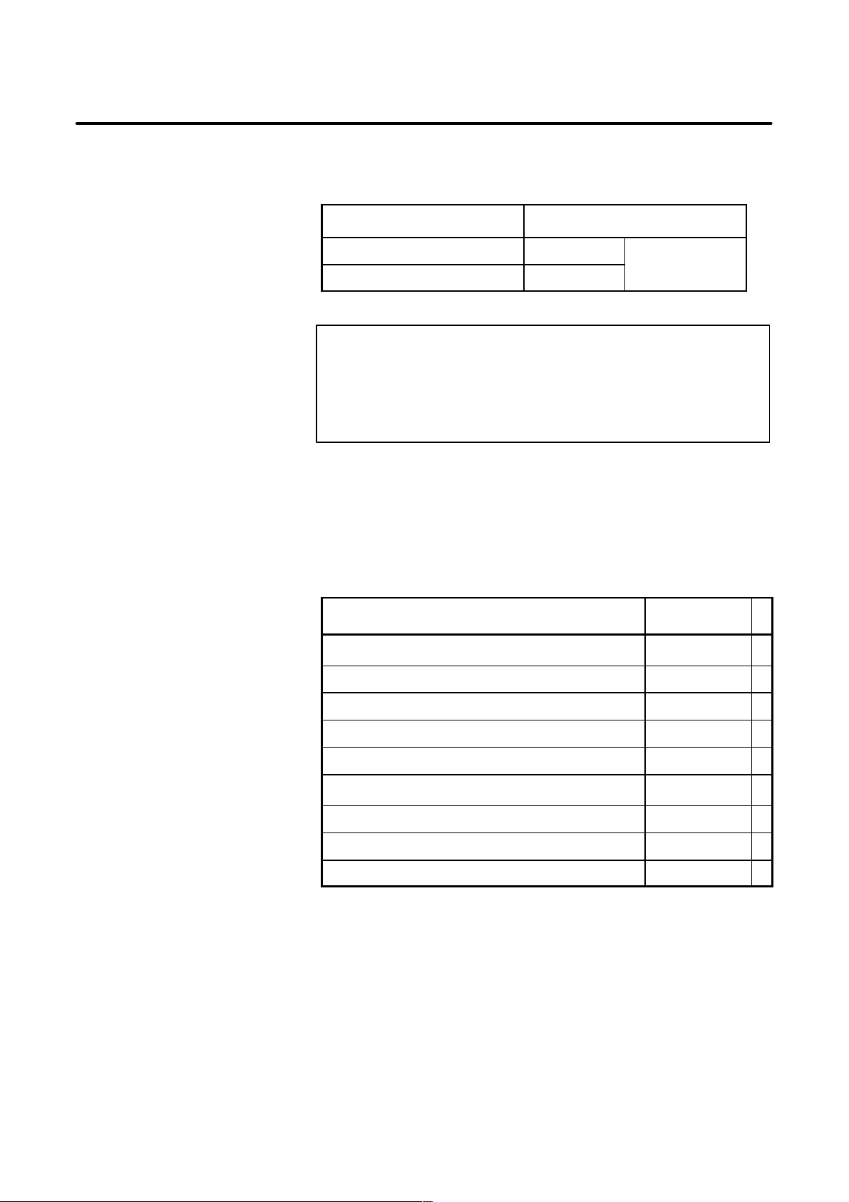
This manual can be used with the following models. The abbreviated
names may be used.
Applicable models
Related manuals
Pruduct name Abbreviation
FANUC Series 15i–MA 15i–MA
FANUC Series 150i–MA 150i–MA
M series
NOTE
Some function described in this manual may not be applied
to some products.
For details, refer to the DESCRIPTIONS manual
(B–63322EN)
The table below lists manuals related to FANUC Series
15i/150i–MODEL A.
In the table, this manual is marked with an asterisk(*).
Table 1 Related manuals
Manual name
DESCRIPTIONS B–63322EN
Specification
number
*
CONNECTION MANUAL (Hardware) B–63323EN
CONNECTION MANUAL (Function) B–63323EN–1
OPERATOR’S MANUAL (PROGRAMMING) B–63324EN
OPERATOR’S MANUAL (OPERA TION) B–63324EN–1
MAINTENANCE MANUAL B–63325EN
PARAMETER MANUAL B–63330EN
DESCRIPTIONS (Supplement for Remote Buffer) B–63322EN–1
PROGRAMMING MANUAL (Macro Compiler/Macro Executor) B–63323EN–2
p–2

B–63325EN/03
Table of Contents
SAFETY PRECAUTIONS s–1. . . . . . . . . . . . . . . . . . . . . . . . . . . . . . . . . . . . . . . . . . . . . . . . . .
PREFACE p–1. . . . . . . . . . . . . . . . . . . . . . . . . . . . . . . . . . . . . . . . . . . . . . . . . . . . . . . . . . . . . . . .
1. SCREEN INDICATIONS AND OPERATIONS 1. . . . . . . . . . . . . . . . . . . . . . . . . . . . . .
1.1 FUNCTION KEYS AND SOFT KEYS 2. . . . . . . . . . . . . . . . . . . . . . . . . . . . . . . . . . . . . . . . . . . . . . .
1.1.1 Indication Procedure for General Screens 2. . . . . . . . . . . . . . . . . . . . . . . . . . . . . . . . . . . . . . . . . . . . . . .
1.1.2 T ypes of Function Keys 3. . . . . . . . . . . . . . . . . . . . . . . . . . . . . . . . . . . . . . . . . . . . . . . . . . . . . . . . . . . .
1.1.3 Soft Keys 3. . . . . . . . . . . . . . . . . . . . . . . . . . . . . . . . . . . . . . . . . . . . . . . . . . . . . . . . . . . . . . . . . . . . . . .
1.1.4 Function Selection Keys 4. . . . . . . . . . . . . . . . . . . . . . . . . . . . . . . . . . . . . . . . . . . . . . . . . . . . . . . . . . . .
1.1.5 Chapter Selection Keys 5. . . . . . . . . . . . . . . . . . . . . . . . . . . . . . . . . . . . . . . . . . . . . . . . . . . . . . . . . . . . .
1.1.5.1 Position 5. . . . . . . . . . . . . . . . . . . . . . . . . . . . . . . . . . . . . . . . . . . . . . . . . . . . . . . . . . . . . . . . . .
1.1.5.2 Program 6. . . . . . . . . . . . . . . . . . . . . . . . . . . . . . . . . . . . . . . . . . . . . . . . . . . . . . . . . . . . . . . . . .
1.1.5.3 Offset/setting 7. . . . . . . . . . . . . . . . . . . . . . . . . . . . . . . . . . . . . . . . . . . . . . . . . . . . . . . . . . . . . .
1.1.5.4 System 8. . . . . . . . . . . . . . . . . . . . . . . . . . . . . . . . . . . . . . . . . . . . . . . . . . . . . . . . . . . . . . . . . . .
1.1.5.5 Messages 9. . . . . . . . . . . . . . . . . . . . . . . . . . . . . . . . . . . . . . . . . . . . . . . . . . . . . . . . . . . . . . . . .
1.1.5.6 Drawing 9. . . . . . . . . . . . . . . . . . . . . . . . . . . . . . . . . . . . . . . . . . . . . . . . . . . . . . . . . . . . . . . . . .
1.2 SCREEN INDICATIONS AT POWER ON 10. . . . . . . . . . . . . . . . . . . . . . . . . . . . . . . . . . . . . . . . . . . .
1.3 DIAGNOSIS FUNCTION 11. . . . . . . . . . . . . . . . . . . . . . . . . . . . . . . . . . . . . . . . . . . . . . . . . . . . . . . . .
1.4 CNC STATE INDICATIONS 22. . . . . . . . . . . . . . . . . . . . . . . . . . . . . . . . . . . . . . . . . . . . . . . . . . . . . . .
1.5 WAVEFORM DIAGNOSIS FUNCTION 24. . . . . . . . . . . . . . . . . . . . . . . . . . . . . . . . . . . . . . . . . . . . . .
1.5.1 Enhancement of Waveform Diagnosis Function 39. . . . . . . . . . . . . . . . . . . . . . . . . . . . . . . . . . . . . . . . . .
1.6 DISPLAYING INTERNAL POSITION COMPENSATION DATA 44. . . . . . . . . . . . . . . . . . . . . . . . .
1.7 OPERATIONS 54. . . . . . . . . . . . . . . . . . . . . . . . . . . . . . . . . . . . . . . . . . . . . . . . . . . . . . . . . . . . . . . . . .
1.8 WARNING SCREEN FOR OPTION CHANGE 58. . . . . . . . . . . . . . . . . . . . . . . . . . . . . . . . . . . . . . . .
1.9 WARNING SCREEN FOR SYSTEM–SOFTWARE REPLACEMENT
(SYSTEM–LABEL CHECK ERROR) 60. . . . . . . . . . . . . . . . . . . . . . . . . . . . . . . . . . . . . . . . . . . . . . .
1.10 MAINTENANCE INFORMATION SCREEN 61. . . . . . . . . . . . . . . . . . . . . . . . . . . . . . . . . . . . . . . . . .
1.10.1 Display 61. . . . . . . . . . . . . . . . . . . . . . . . . . . . . . . . . . . . . . . . . . . . . . . . . . . . . . . . . . . . . . . . . . . . . . . . .
1.10.2 Procedures 63. . . . . . . . . . . . . . . . . . . . . . . . . . . . . . . . . . . . . . . . . . . . . . . . . . . . . . . . . . . . . . . . . . . . . .
1.10.3 Half–size Kana Input 68. . . . . . . . . . . . . . . . . . . . . . . . . . . . . . . . . . . . . . . . . . . . . . . . . . . . . . . . . . . . . .
1.10.4 Parameter 69. . . . . . . . . . . . . . . . . . . . . . . . . . . . . . . . . . . . . . . . . . . . . . . . . . . . . . . . . . . . . . . . . . . . . . .
1.11 PERIODIC MAINTENANCE SCREEN 70. . . . . . . . . . . . . . . . . . . . . . . . . . . . . . . . . . . . . . . . . . . . . .
1.11.1 Display 70. . . . . . . . . . . . . . . . . . . . . . . . . . . . . . . . . . . . . . . . . . . . . . . . . . . . . . . . . . . . . . . . . . . . . . . . .
1.11.2 Procedures 72. . . . . . . . . . . . . . . . . . . . . . . . . . . . . . . . . . . . . . . . . . . . . . . . . . . . . . . . . . . . . . . . . . . . . .
1.11.3 Inputting and Outputting Set Items 75. . . . . . . . . . . . . . . . . . . . . . . . . . . . . . . . . . . . . . . . . . . . . . . . . . . .
1.12 SYSTEM LOG SCREEN 80. . . . . . . . . . . . . . . . . . . . . . . . . . . . . . . . . . . . . . . . . . . . . . . . . . . . . . . . . .
1.12.1 Display 80. . . . . . . . . . . . . . . . . . . . . . . . . . . . . . . . . . . . . . . . . . . . . . . . . . . . . . . . . . . . . . . . . . . . . . . . .
1.12.2 Procedures 84. . . . . . . . . . . . . . . . . . . . . . . . . . . . . . . . . . . . . . . . . . . . . . . . . . . . . . . . . . . . . . . . . . . . . .
1.12.3 Parameter 86. . . . . . . . . . . . . . . . . . . . . . . . . . . . . . . . . . . . . . . . . . . . . . . . . . . . . . . . . . . . . . . . . . . . . . .
1.13 SYSTEM CONFIGURATION SCREEN 87. . . . . . . . . . . . . . . . . . . . . . . . . . . . . . . . . . . . . . . . . . . . . .
1.13.1 Displaying the System Configuration Screen 87. . . . . . . . . . . . . . . . . . . . . . . . . . . . . . . . . . . . . . . . . . . .
1.13.2 Printed Circuit Board Configuration Screen 87. . . . . . . . . . . . . . . . . . . . . . . . . . . . . . . . . . . . . . . . . . . . .
1.13.3 Software Configuration Screen 89. . . . . . . . . . . . . . . . . . . . . . . . . . . . . . . . . . . . . . . . . . . . . . . . . . . . . . .
1.13.4 Module Configuration Screen 91. . . . . . . . . . . . . . . . . . . . . . . . . . . . . . . . . . . . . . . . . . . . . . . . . . . . . . . .
1.14 MEMORY CONTENTS INDICATIONS 92. . . . . . . . . . . . . . . . . . . . . . . . . . . . . . . . . . . . . . . . . . . . . .
1.15 TOUCH PANEL 96. . . . . . . . . . . . . . . . . . . . . . . . . . . . . . . . . . . . . . . . . . . . . . . . . . . . . . . . . . . . . . . . .
1.16 BIOS/SETUP OF THE INTELLIGENT TERMINAL 99. . . . . . . . . . . . . . . . . . . . . . . . . . . . . . . . . . . .
1.16.1 BIOS/SETUP 99. . . . . . . . . . . . . . . . . . . . . . . . . . . . . . . . . . . . . . . . . . . . . . . . . . . . . . . . . . . . . . . . . . . .
1.16.2 Functions of Keys on the Setup Screen 99. . . . . . . . . . . . . . . . . . . . . . . . . . . . . . . . . . . . . . . . . . . . . . . . .
c–1

Table of Contents
1.16.3 Setup Method 100. . . . . . . . . . . . . . . . . . . . . . . . . . . . . . . . . . . . . . . . . . . . . . . . . . . . . . . . . . . . . . . . . . . .
1.16.4 BIOS Messages 101. . . . . . . . . . . . . . . . . . . . . . . . . . . . . . . . . . . . . . . . . . . . . . . . . . . . . . . . . . . . . . . . . .
1.16.5 BIOS Menu Details 102. . . . . . . . . . . . . . . . . . . . . . . . . . . . . . . . . . . . . . . . . . . . . . . . . . . . . . . . . . . . . . .
1.16.5.1 Main menu 102. . . . . . . . . . . . . . . . . . . . . . . . . . . . . . . . . . . . . . . . . . . . . . . . . . . . . . . . . . . . . . . .
1.16.5.2 Advance menu 103. . . . . . . . . . . . . . . . . . . . . . . . . . . . . . . . . . . . . . . . . . . . . . . . . . . . . . . . . . . . .
1.16.5.3 Power savings menu 104. . . . . . . . . . . . . . . . . . . . . . . . . . . . . . . . . . . . . . . . . . . . . . . . . . . . . . . . .
1.16.5.4 Exit menu 105. . . . . . . . . . . . . . . . . . . . . . . . . . . . . . . . . . . . . . . . . . . . . . . . . . . . . . . . . . . . . . . . .
B–63325EN/03
2. 15i SERIES HARDWARE 106. . . . . . . . . . . . . . . . . . . . . . . . . . . . . . . . . . . . . . . . . . . . . . .
2.1 HARDWARE CONFIGURATION 107. . . . . . . . . . . . . . . . . . . . . . . . . . . . . . . . . . . . . . . . . . . . . . . . . . .
2.2 OVERVIEW OF HARDWARE 108. . . . . . . . . . . . . . . . . . . . . . . . . . . . . . . . . . . . . . . . . . . . . . . . . . . . .
2.2.1 Series 15i/150i 108. . . . . . . . . . . . . . . . . . . . . . . . . . . . . . . . . . . . . . . . . . . . . . . . . . . . . . . . . . . . . . . . . . .
2.3 CONNECTOR LOCATIONS AND CARD CONFIGURATION
FOR EACH PRINTED CIRCUIT BOARD 110. . . . . . . . . . . . . . . . . . . . . . . . . . . . . . . . . . . . . . . . . . . .
2.3.1 FS15i/150i Main Board 110. . . . . . . . . . . . . . . . . . . . . . . . . . . . . . . . . . . . . . . . . . . . . . . . . . . . . . . . . . . .
2.3.2 FS15i/150i Additional Axis Board 118. . . . . . . . . . . . . . . . . . . . . . . . . . . . . . . . . . . . . . . . . . . . . . . . . . . .
2.3.3 FS15i/150i LCD Unit 121. . . . . . . . . . . . . . . . . . . . . . . . . . . . . . . . . . . . . . . . . . . . . . . . . . . . . . . . . . . . . .
2.3.3.1 Connection for one unit 121. . . . . . . . . . . . . . . . . . . . . . . . . . . . . . . . . . . . . . . . . . . . . . . . . . . . . .
2.3.3.2 Connection for two units (10.4”) 123. . . . . . . . . . . . . . . . . . . . . . . . . . . . . . . . . . . . . . . . . . . . . . .
2.3.4 FS15i/150i Inverter PCB 125. . . . . . . . . . . . . . . . . . . . . . . . . . . . . . . . . . . . . . . . . . . . . . . . . . . . . . . . . . .
2.3.5 Data Server Board A1 126. . . . . . . . . . . . . . . . . . . . . . . . . . . . . . . . . . . . . . . . . . . . . . . . . . . . . . . . . . . . . .
2.3.6 Data Server Board A2 128. . . . . . . . . . . . . . . . . . . . . . . . . . . . . . . . . . . . . . . . . . . . . . . . . . . . . . . . . . . . . .
2.3.7 HSSB Interface Board 129. . . . . . . . . . . . . . . . . . . . . . . . . . . . . . . . . . . . . . . . . . . . . . . . . . . . . . . . . . . . .
2.3.8 PMC C Board 132. . . . . . . . . . . . . . . . . . . . . . . . . . . . . . . . . . . . . . . . . . . . . . . . . . . . . . . . . . . . . . . . . . . .
2.3.9 Serial Communication Boards A1 and A2 133. . . . . . . . . . . . . . . . . . . . . . . . . . . . . . . . . . . . . . . . . . . . . .
2.3.10 DeviceNet Board B 136. . . . . . . . . . . . . . . . . . . . . . . . . . . . . . . . . . . . . . . . . . . . . . . . . . . . . . . . . . . . . . . .
2.3.11 DeviceNet Slave Board C 138. . . . . . . . . . . . . . . . . . . . . . . . . . . . . . . . . . . . . . . . . . . . . . . . . . . . . . . . . . .
2.3.12 Ethernet Board 141. . . . . . . . . . . . . . . . . . . . . . . . . . . . . . . . . . . . . . . . . . . . . . . . . . . . . . . . . . . . . . . . . . .
2.3.13 PROFIBUS–DP Board (Master) 143. . . . . . . . . . . . . . . . . . . . . . . . . . . . . . . . . . . . . . . . . . . . . . . . . . . . . .
2.3.14 PROFIBUS–DP Board (Slave) 144. . . . . . . . . . . . . . . . . . . . . . . . . . . . . . . . . . . . . . . . . . . . . . . . . . . . . . .
2.4 LIST OF THE UNITS AND PRINTED CIRCUIT BOARDS 145. . . . . . . . . . . . . . . . . . . . . . . . . . . . . .
2.4.1 Basic Unit 145. . . . . . . . . . . . . . . . . . . . . . . . . . . . . . . . . . . . . . . . . . . . . . . . . . . . . . . . . . . . . . . . . . . . . . .
2.4.2 Power Supply Unit 145. . . . . . . . . . . . . . . . . . . . . . . . . . . . . . . . . . . . . . . . . . . . . . . . . . . . . . . . . . . . . . . .
2.4.3 LCD Unit 145. . . . . . . . . . . . . . . . . . . . . . . . . . . . . . . . . . . . . . . . . . . . . . . . . . . . . . . . . . . . . . . . . . . . . . .
2.4.4 Stand–alone T ype MDI Unit 146. . . . . . . . . . . . . . . . . . . . . . . . . . . . . . . . . . . . . . . . . . . . . . . . . . . . . . . . .
2.4.5 Intelligent T erminal 147. . . . . . . . . . . . . . . . . . . . . . . . . . . . . . . . . . . . . . . . . . . . . . . . . . . . . . . . . . . . . . . .
2.4.5.1 Intelligent terminal (A13B–0178–B025 to –B042) 147. . . . . . . . . . . . . . . . . . . . . . . . . . . . . . . . .
2.4.5.2 Panel i (A08B–0082–B001 to –B023) 148. . . . . . . . . . . . . . . . . . . . . . . . . . . . . . . . . . . . . . . . . . .
2.4.5.3 Other options for intelligent terminal and panel i 149. . . . . . . . . . . . . . . . . . . . . . . . . . . . . . . . . . .
2.4.6 Data Server Hard Disk Unit 150. . . . . . . . . . . . . . . . . . . . . . . . . . . . . . . . . . . . . . . . . . . . . . . . . . . . . . . . .
2.4.7 Printed Circuit Boards of the Control Unit 151. . . . . . . . . . . . . . . . . . . . . . . . . . . . . . . . . . . . . . . . . . . . . .
2.4.8 Others 156. . . . . . . . . . . . . . . . . . . . . . . . . . . . . . . . . . . . . . . . . . . . . . . . . . . . . . . . . . . . . . . . . . . . . . . . . .
2.4.9 Maintenance Parts 157. . . . . . . . . . . . . . . . . . . . . . . . . . . . . . . . . . . . . . . . . . . . . . . . . . . . . . . . . . . . . . . . .
2.4.10 Intelligent Terminal and Panel i Maintenance Equipment 158. . . . . . . . . . . . . . . . . . . . . . . . . . . . . . . . . . .
2.4.11 Machine Operators Panel 158. . . . . . . . . . . . . . . . . . . . . . . . . . . . . . . . . . . . . . . . . . . . . . . . . . . . . . . . . . .
2.5 REPLACING THE PRINTED CIRCUIT BOARDS 159. . . . . . . . . . . . . . . . . . . . . . . . . . . . . . . . . . . . .
2.5.1 Replacing the Power Supply Unit, Main CPU Board, and Full–size Option Board 159. . . . . . . . . . . . . . .
2.5.1.1 Demounting the board 160. . . . . . . . . . . . . . . . . . . . . . . . . . . . . . . . . . . . . . . . . . . . . . . . . . . . . . .
2.5.1.2 Mounting a board 160. . . . . . . . . . . . . . . . . . . . . . . . . . . . . . . . . . . . . . . . . . . . . . . . . . . . . . . . . . .
2.5.2 Replacing the Mini Slot Option Board and Wide Mini Slot Option Board 161. . . . . . . . . . . . . . . . . . . . . .
2.5.2.1 Demounting the board 161. . . . . . . . . . . . . . . . . . . . . . . . . . . . . . . . . . . . . . . . . . . . . . . . . . . . . . .
2.5.2.2 Mounting a board 161. . . . . . . . . . . . . . . . . . . . . . . . . . . . . . . . . . . . . . . . . . . . . . . . . . . . . . . . . . .
c–2

B–63325EN/03
2.6 MOUNTING AND DEMOUNTING CARD PCBS 164. . . . . . . . . . . . . . . . . . . . . . . . . . . . . . . . . . . . . .
2.7 MOUNTING AND DEMOUNTING DIMM MODULES 167. . . . . . . . . . . . . . . . . . . . . . . . . . . . . . . . .
2.8 REPLACING THE BACK PANEL 169. . . . . . . . . . . . . . . . . . . . . . . . . . . . . . . . . . . . . . . . . . . . . . . . . .
2.9 REPLACING FUSE ON POWER UNIT 171. . . . . . . . . . . . . . . . . . . . . . . . . . . . . . . . . . . . . . . . . . . . . .
2.10 REPLACING THE BATTERY 172. . . . . . . . . . . . . . . . . . . . . . . . . . . . . . . . . . . . . . . . . . . . . . . . . . . . . .
2.11 REPLACING THE FAN MOTORS 176. . . . . . . . . . . . . . . . . . . . . . . . . . . . . . . . . . . . . . . . . . . . . . . . . .
2.12 LCD UNIT FUSE REPLACEMENT 177. . . . . . . . . . . . . . . . . . . . . . . . . . . . . . . . . . . . . . . . . . . . . . . . .
2.13 LCD BACKLIGHT REPLACEMENT 178. . . . . . . . . . . . . . . . . . . . . . . . . . . . . . . . . . . . . . . . . . . . . . .
2.14 LIQUID CRYSTAL DISPLAY (LCD) 181. . . . . . . . . . . . . . . . . . . . . . . . . . . . . . . . . . . . . . . . . . . . . . . .
2.15 INTELLIGENT TERMINAL (A13B–0178–B025 TO –B042) 183. . . . . . . . . . . . . . . . . . . . . . . . . . . . .
2.16 DISTRIBUTED I/O SETTING 203. . . . . . . . . . . . . . . . . . . . . . . . . . . . . . . . . . . . . . . . . . . . . . . . . . . . .
2.17 REPLACING FUSE ON CONTROL UNIT 205. . . . . . . . . . . . . . . . . . . . . . . . . . . . . . . . . . . . . . . . . . .
2.18 ENVIRONMENTAL CONDITIONS OUTSIDE CABINET 212. . . . . . . . . . . . . . . . . . . . . . . . . . . . . . .
2.19 POWER CONSUMPTION OF EACH UNIT 213. . . . . . . . . . . . . . . . . . . . . . . . . . . . . . . . . . . . . . . . . .
2.20 COUNTERMEASURES AGAINST NOISE 215. . . . . . . . . . . . . . . . . . . . . . . . . . . . . . . . . . . . . . . . . . .
Table of Contents
2.5.3 Mounting and Removing the DeviceNet Board 162. . . . . . . . . . . . . . . . . . . . . . . . . . . . . . . . . . . . . . . . . .
2.5.3.1 Removing the board 162. . . . . . . . . . . . . . . . . . . . . . . . . . . . . . . . . . . . . . . . . . . . . . . . . . . . . . . . .
2.5.3.2 Mounting the board 163. . . . . . . . . . . . . . . . . . . . . . . . . . . . . . . . . . . . . . . . . . . . . . . . . . . . . . . . .
2.6.1 Demounting a Card PCB 165. . . . . . . . . . . . . . . . . . . . . . . . . . . . . . . . . . . . . . . . . . . . . . . . . . . . . . . . . . .
2.6.2 Mounting a Card PCB 166. . . . . . . . . . . . . . . . . . . . . . . . . . . . . . . . . . . . . . . . . . . . . . . . . . . . . . . . . . . . .
2.7.1 Demounting a DIMM Module 168. . . . . . . . . . . . . . . . . . . . . . . . . . . . . . . . . . . . . . . . . . . . . . . . . . . . . . .
2.7.2 Mounting a DIMM Module 168. . . . . . . . . . . . . . . . . . . . . . . . . . . . . . . . . . . . . . . . . . . . . . . . . . . . . . . . .
2.8.1 Demounting the Back Panel 169. . . . . . . . . . . . . . . . . . . . . . . . . . . . . . . . . . . . . . . . . . . . . . . . . . . . . . . . .
2.8.2 Mounting the Back Panel 170. . . . . . . . . . . . . . . . . . . . . . . . . . . . . . . . . . . . . . . . . . . . . . . . . . . . . . . . . . .
2.10.1 Replacing the Lithium Battery 172. . . . . . . . . . . . . . . . . . . . . . . . . . . . . . . . . . . . . . . . . . . . . . . . . . . . . . .
2.10.2 When Using Alkaline Dry Cells 174. . . . . . . . . . . . . . . . . . . . . . . . . . . . . . . . . . . . . . . . . . . . . . . . . . . . . .
2.15.1 Parts Layout 183. . . . . . . . . . . . . . . . . . . . . . . . . . . . . . . . . . . . . . . . . . . . . . . . . . . . . . . . . . . . . . . . . . . . .
2.15.2 Setting Controls 185. . . . . . . . . . . . . . . . . . . . . . . . . . . . . . . . . . . . . . . . . . . . . . . . . . . . . . . . . . . . . . . . . .
2.15.3 LED Display 186. . . . . . . . . . . . . . . . . . . . . . . . . . . . . . . . . . . . . . . . . . . . . . . . . . . . . . . . . . . . . . . . . . . . .
2.15.4 Mounting Locations of Maintenance Parts 187. . . . . . . . . . . . . . . . . . . . . . . . . . . . . . . . . . . . . . . . . . . . . .
2.15.5 Specifications of Maintenance Parts 189. . . . . . . . . . . . . . . . . . . . . . . . . . . . . . . . . . . . . . . . . . . . . . . . . . .
2.15.6 Replacing the Battery 190. . . . . . . . . . . . . . . . . . . . . . . . . . . . . . . . . . . . . . . . . . . . . . . . . . . . . . . . . . . . . .
2.15.7 Replacing the Fuse 191. . . . . . . . . . . . . . . . . . . . . . . . . . . . . . . . . . . . . . . . . . . . . . . . . . . . . . . . . . . . . . . .
2.15.8 Replacing the Fans 191. . . . . . . . . . . . . . . . . . . . . . . . . . . . . . . . . . . . . . . . . . . . . . . . . . . . . . . . . . . . . . . .
2.15.8.1 Replacing the fan of the main unit of intelligent terminal type 2 191. . . . . . . . . . . . . . . . . . . . . . . .
2.15.8.2 Replacing the fan of the HDD 191. . . . . . . . . . . . . . . . . . . . . . . . . . . . . . . . . . . . . . . . . . . . . . . . .
2.15.9 Replacing the LCD Backlight 192. . . . . . . . . . . . . . . . . . . . . . . . . . . . . . . . . . . . . . . . . . . . . . . . . . . . . . . .
2.15.10 Replacing the Touch Panel Protective Sheet 198. . . . . . . . . . . . . . . . . . . . . . . . . . . . . . . . . . . . . . . . . . . . .
2.15.11 Troubleshooting 200. . . . . . . . . . . . . . . . . . . . . . . . . . . . . . . . . . . . . . . . . . . . . . . . . . . . . . . . . . . . . . . . . .
2.15.12 Notes on Using the MDI Unit 201. . . . . . . . . . . . . . . . . . . . . . . . . . . . . . . . . . . . . . . . . . . . . . . . . . . . . . . .
2.20.1 Separation of Signal Lines 215. . . . . . . . . . . . . . . . . . . . . . . . . . . . . . . . . . . . . . . . . . . . . . . . . . . . . . . . . .
2.20.2 Grounding 217. . . . . . . . . . . . . . . . . . . . . . . . . . . . . . . . . . . . . . . . . . . . . . . . . . . . . . . . . . . . . . . . . . . . . .
2.20.3 Control Unit Grounding 218. . . . . . . . . . . . . . . . . . . . . . . . . . . . . . . . . . . . . . . . . . . . . . . . . . . . . . . . . . . .
2.20.4 Noise Suppressor 219. . . . . . . . . . . . . . . . . . . . . . . . . . . . . . . . . . . . . . . . . . . . . . . . . . . . . . . . . . . . . . . . .
2.20.5 Cable Clamping and Shielding 220. . . . . . . . . . . . . . . . . . . . . . . . . . . . . . . . . . . . . . . . . . . . . . . . . . . . . . .
3. DATA INPUT/OUTPUT 223. . . . . . . . . . . . . . . . . . . . . . . . . . . . . . . . . . . . . . . . . . . . . . . . . .
3.1 SPECIFYING PARAMETERS REQUIRED FOR INPUT/OUTPUT 224. . . . . . . . . . . . . . . . . . . . . . . .
3.1.1 Setting Parameter Screen 224. . . . . . . . . . . . . . . . . . . . . . . . . . . . . . . . . . . . . . . . . . . . . . . . . . . . . . . . . . .
3.1.2 Communication Setting Screen 225. . . . . . . . . . . . . . . . . . . . . . . . . . . . . . . . . . . . . . . . . . . . . . . . . . . . . . .
c–3

Table of Contents
B–63325EN/03
3.2 DATA INPUT/OUTPUT 228. . . . . . . . . . . . . . . . . . . . . . . . . . . . . . . . . . . . . . . . . . . . . . . . . . . . . . . . . . .
3.2.1 Output of Part Programs 228. . . . . . . . . . . . . . . . . . . . . . . . . . . . . . . . . . . . . . . . . . . . . . . . . . . . . . . . . . . .
3.2.2 Output of System Parameters 234. . . . . . . . . . . . . . . . . . . . . . . . . . . . . . . . . . . . . . . . . . . . . . . . . . . . . . . .
3.2.3 Output of W orkpiece Origin Of fset Data 235. . . . . . . . . . . . . . . . . . . . . . . . . . . . . . . . . . . . . . . . . . . . . . . .
3.2.4 Output of Pitch Error Compensation Data 236. . . . . . . . . . . . . . . . . . . . . . . . . . . . . . . . . . . . . . . . . . . . . .
3.2.5 Output of T ool Of fset Data 237. . . . . . . . . . . . . . . . . . . . . . . . . . . . . . . . . . . . . . . . . . . . . . . . . . . . . . . . . .
3.2.6 Output of Custom Macro Variables 238. . . . . . . . . . . . . . . . . . . . . . . . . . . . . . . . . . . . . . . . . . . . . . . . . . . .
3.2.7 Output of Volumetric Compensation Data 239. . . . . . . . . . . . . . . . . . . . . . . . . . . . . . . . . . . . . . . . . . . . . .
3.2.8 Output of Tool Offset Data by Tool Number 241. . . . . . . . . . . . . . . . . . . . . . . . . . . . . . . . . . . . . . . . . . . . .
3.2.9 Output of Fixture Offset Data 242. . . . . . . . . . . . . . . . . . . . . . . . . . . . . . . . . . . . . . . . . . . . . . . . . . . . . . . .
3.2.10 Output of Rotary Head Dynamic T ool Compensation Data 243. . . . . . . . . . . . . . . . . . . . . . . . . . . . . . . . .
3.2.11 Output of Periodic Maintenance Data 244. . . . . . . . . . . . . . . . . . . . . . . . . . . . . . . . . . . . . . . . . . . . . . . . . .
3.2.12 Output of Item Selection Menu (Machine System) Data 245. . . . . . . . . . . . . . . . . . . . . . . . . . . . . . . . . . . .
3.2.13 Output of Maintenance Information 247. . . . . . . . . . . . . . . . . . . . . . . . . . . . . . . . . . . . . . . . . . . . . . . . . . .
3.2.14 Output of System Configuration Data 248. . . . . . . . . . . . . . . . . . . . . . . . . . . . . . . . . . . . . . . . . . . . . . . . . .
3.2.15 Output of System Log Data 249. . . . . . . . . . . . . . . . . . . . . . . . . . . . . . . . . . . . . . . . . . . . . . . . . . . . . . . . .
3.2.16 Input of Part Programs 250. . . . . . . . . . . . . . . . . . . . . . . . . . . . . . . . . . . . . . . . . . . . . . . . . . . . . . . . . . . . .
3.2.17 Output of System Parameters 253. . . . . . . . . . . . . . . . . . . . . . . . . . . . . . . . . . . . . . . . . . . . . . . . . . . . . . . .
3.2.18 Input of W orkpiece Origin Of fset Data 254. . . . . . . . . . . . . . . . . . . . . . . . . . . . . . . . . . . . . . . . . . . . . . . . .
3.2.19 Input of Pitch Error Compensation Data 255. . . . . . . . . . . . . . . . . . . . . . . . . . . . . . . . . . . . . . . . . . . . . . . .
3.2.20 Input of T ool Of fset Data 256. . . . . . . . . . . . . . . . . . . . . . . . . . . . . . . . . . . . . . . . . . . . . . . . . . . . . . . . . . .
3.2.21 Input of Custom Macro Variables 257. . . . . . . . . . . . . . . . . . . . . . . . . . . . . . . . . . . . . . . . . . . . . . . . . . . . .
3.2.22 Output of Volumetric Compensation Data 258. . . . . . . . . . . . . . . . . . . . . . . . . . . . . . . . . . . . . . . . . . . . . .
3.2.23 Input of Tool Offset Data by Tool Number 259. . . . . . . . . . . . . . . . . . . . . . . . . . . . . . . . . . . . . . . . . . . . . .
3.2.24 Input of Fixture Offset Data 260. . . . . . . . . . . . . . . . . . . . . . . . . . . . . . . . . . . . . . . . . . . . . . . . . . . . . . . . .
3.2.25 Input of Rotary Head Dynamic T ool Compensation Data 261. . . . . . . . . . . . . . . . . . . . . . . . . . . . . . . . . . .
3.2.26 Input of Periodic Maintenance Data 262. . . . . . . . . . . . . . . . . . . . . . . . . . . . . . . . . . . . . . . . . . . . . . . . . . .
3.2.27 Input of Item Selection Menu (Machine System) Data 263. . . . . . . . . . . . . . . . . . . . . . . . . . . . . . . . . . . . .
3.2.28 Input of Maintenance Information 265. . . . . . . . . . . . . . . . . . . . . . . . . . . . . . . . . . . . . . . . . . . . . . . . . . . .
3.3 FLOPPY DIRECTORY SCREEN 266. . . . . . . . . . . . . . . . . . . . . . . . . . . . . . . . . . . . . . . . . . . . . . . . . . .
3.4 MEMORY CARD SCREEN 271. . . . . . . . . . . . . . . . . . . . . . . . . . . . . . . . . . . . . . . . . . . . . . . . . . . . . . . .
4. INTERFACE BETWEEN THE NC AND PMC 277. . . . . . . . . . . . . . . . . . . . . . . . . . . . . .
4.1 INTERFACE OVERVIEW 278. . . . . . . . . . . . . . . . . . . . . . . . . . . . . . . . . . . . . . . . . . . . . . . . . . . . . . . . .
4.2 PMC SPECIFICATION 279. . . . . . . . . . . . . . . . . . . . . . . . . . . . . . . . . . . . . . . . . . . . . . . . . . . . . . . . . . .
4.2.1 PMC Specification List 279. . . . . . . . . . . . . . . . . . . . . . . . . . . . . . . . . . . . . . . . . . . . . . . . . . . . . . . . . . . . .
4.2.2 Addresses 280. . . . . . . . . . . . . . . . . . . . . . . . . . . . . . . . . . . . . . . . . . . . . . . . . . . . . . . . . . . . . . . . . . . . . . .
4.2.3 Built–in Debugging Functions 280. . . . . . . . . . . . . . . . . . . . . . . . . . . . . . . . . . . . . . . . . . . . . . . . . . . . . . .
4.2.4 Internal Relay System–reserved Area 281. . . . . . . . . . . . . . . . . . . . . . . . . . . . . . . . . . . . . . . . . . . . . . . . . .
4.2.5 PMC Execution Cycle 282. . . . . . . . . . . . . . . . . . . . . . . . . . . . . . . . . . . . . . . . . . . . . . . . . . . . . . . . . . . . .
4.3 PMC DISPLAYS 283. . . . . . . . . . . . . . . . . . . . . . . . . . . . . . . . . . . . . . . . . . . . . . . . . . . . . . . . . . . . . . . . .
4.3.1 Overview 283. . . . . . . . . . . . . . . . . . . . . . . . . . . . . . . . . . . . . . . . . . . . . . . . . . . . . . . . . . . . . . . . . . . . . . .
4.3.2 PMC Menu Selection Procedure Based on Soft Keys 284. . . . . . . . . . . . . . . . . . . . . . . . . . . . . . . . . . . . . .
4.3.2.1 PMC basic menu 284. . . . . . . . . . . . . . . . . . . . . . . . . . . . . . . . . . . . . . . . . . . . . . . . . . . . . . . . . . .
4.3.2.2 PMC screen transition flow and the related soft keys 286. . . . . . . . . . . . . . . . . . . . . . . . . . . . . . . .
4.3.3 PMC Input/Output Signal and Internal–relay Displays (PMCDGN) 287. . . . . . . . . . . . . . . . . . . . . . . . . . .
4.3.3.1 T itle data display (TITLE) 287. . . . . . . . . . . . . . . . . . . . . . . . . . . . . . . . . . . . . . . . . . . . . . . . . . . .
4.3.3.2 Signal status display (STATUS) 288. . . . . . . . . . . . . . . . . . . . . . . . . . . . . . . . . . . . . . . . . . . . . . . .
4.3.3.3 Alarm screen (ALARM) 289. . . . . . . . . . . . . . . . . . . . . . . . . . . . . . . . . . . . . . . . . . . . . . . . . . . . . .
4.3.4 PMC Data Setting and Display (PMCPRM) 290. . . . . . . . . . . . . . . . . . . . . . . . . . . . . . . . . . . . . . . . . . . . .
4.3.4.1 Overview 290. . . . . . . . . . . . . . . . . . . . . . . . . . . . . . . . . . . . . . . . . . . . . . . . . . . . . . . . . . . . . . . . .
4.3.4.2 PMC parameter entry method 290. . . . . . . . . . . . . . . . . . . . . . . . . . . . . . . . . . . . . . . . . . . . . . . . . .
4.3.4.3 Continuous data entry 291. . . . . . . . . . . . . . . . . . . . . . . . . . . . . . . . . . . . . . . . . . . . . . . . . . . . . . .
c–4

B–63325EN/03
4.3.4.4 T imer screen (TIMER) 291. . . . . . . . . . . . . . . . . . . . . . . . . . . . . . . . . . . . . . . . . . . . . . . . . . . . . . .
4.3.4.5 Counter screen (COUNTR) 292. . . . . . . . . . . . . . . . . . . . . . . . . . . . . . . . . . . . . . . . . . . . . . . . . . .
4.3.4.6 Keep relay screen (KEEPRL) 293. . . . . . . . . . . . . . . . . . . . . . . . . . . . . . . . . . . . . . . . . . . . . . . . . .
4.3.4.7 Data table (DATA) 295. . . . . . . . . . . . . . . . . . . . . . . . . . . . . . . . . . . . . . . . . . . . . . . . . . . . . . . . . .
4.3.5 Setting Menu (SETING) 297. . . . . . . . . . . . . . . . . . . . . . . . . . . . . . . . . . . . . . . . . . . . . . . . . . . . . . . . . . . .
4.3.5.1 General–setting data display screen (GENERAL) 298. . . . . . . . . . . . . . . . . . . . . . . . . . . . . . . . . .
4.3.5.2 Screen for displaying setting data related to editing and debugging 299. . . . . . . . . . . . . . . . . . . . .
4.3.5.3 Online monitor parameter display/setting screen (ONLINE) 299. . . . . . . . . . . . . . . . . . . . . . . . . .
Table of Contents
4.4 DI/DO MONITOR FUNCTION 302. . . . . . . . . . . . . . . . . . . . . . . . . . . . . . . . . . . . . . . . . . . . . . . . . . . . .
4.4.1 DI/DO Monitor Screen 302. . . . . . . . . . . . . . . . . . . . . . . . . . . . . . . . . . . . . . . . . . . . . . . . . . . . . . . . . . . . .
4.4.2 Screen Manipulation 305. . . . . . . . . . . . . . . . . . . . . . . . . . . . . . . . . . . . . . . . . . . . . . . . . . . . . . . . . . . . . . .
5. DIGITAL SERVO 306. . . . . . . . . . . . . . . . . . . . . . . . . . . . . . . . . . . . . . . . . . . . . . . . . . . . . . .
5.1 SERVO PARAMETER INITIALIZATION PROCEDURE 307. . . . . . . . . . . . . . . . . . . . . . . . . . . . . . . .
5.2 SETTING THE FSSB 312. . . . . . . . . . . . . . . . . . . . . . . . . . . . . . . . . . . . . . . . . . . . . . . . . . . . . . . . . . . . .
5.3 SERVO SCREENS 324. . . . . . . . . . . . . . . . . . . . . . . . . . . . . . . . . . . . . . . . . . . . . . . . . . . . . . . . . . . . . . .
5.3.1 Parameter Setting 324. . . . . . . . . . . . . . . . . . . . . . . . . . . . . . . . . . . . . . . . . . . . . . . . . . . . . . . . . . . . . . . . .
5.3.2 Displaying Servo Screens 324. . . . . . . . . . . . . . . . . . . . . . . . . . . . . . . . . . . . . . . . . . . . . . . . . . . . . . . . . . .
5.4 REFERENCE POSITION RETURN ADJUSTMENT (BASED ON DOGS) 332. . . . . . . . . . . . . . . . . .
5.4.1 Overview 332. . . . . . . . . . . . . . . . . . . . . . . . . . . . . . . . . . . . . . . . . . . . . . . . . . . . . . . . . . . . . . . . . . . . . . .
5.5 SETTING THE REFERENCE POSITION WITHOUT DOGS 335. . . . . . . . . . . . . . . . . . . . . . . . . . . . .
5.5.1 Overview 335. . . . . . . . . . . . . . . . . . . . . . . . . . . . . . . . . . . . . . . . . . . . . . . . . . . . . . . . . . . . . . . . . . . . . . .
5.5.2 Operating Procedure 335. . . . . . . . . . . . . . . . . . . . . . . . . . . . . . . . . . . . . . . . . . . . . . . . . . . . . . . . . . . . . . .
5.5.3 Related Parameters 336. . . . . . . . . . . . . . . . . . . . . . . . . . . . . . . . . . . . . . . . . . . . . . . . . . . . . . . . . . . . . . . .
6. AC SPINDLES 337. . . . . . . . . . . . . . . . . . . . . . . . . . . . . . . . . . . . . . . . . . . . . . . . . . . . . . . . .
6.1 SERIAL INTERFACE AC SPINDLE 338. . . . . . . . . . . . . . . . . . . . . . . . . . . . . . . . . . . . . . . . . . . . . . . .
6.1.1 Spindle Control Overview 338. . . . . . . . . . . . . . . . . . . . . . . . . . . . . . . . . . . . . . . . . . . . . . . . . . . . . . . . . .
6.1.2 Spindle Screens 340. . . . . . . . . . . . . . . . . . . . . . . . . . . . . . . . . . . . . . . . . . . . . . . . . . . . . . . . . . . . . . . . . .
6.1.2.1 Parameters 340. . . . . . . . . . . . . . . . . . . . . . . . . . . . . . . . . . . . . . . . . . . . . . . . . . . . . . . . . . . . . . . .
6.1.2.2 Spindle screens 341. . . . . . . . . . . . . . . . . . . . . . . . . . . . . . . . . . . . . . . . . . . . . . . . . . . . . . . . . . . . .
6.1.3 Automatic Setting of Standard Parameters 350. . . . . . . . . . . . . . . . . . . . . . . . . . . . . . . . . . . . . . . . . . . . . .
6.2 ANALOG INTERFACE AC SPINDLE 351. . . . . . . . . . . . . . . . . . . . . . . . . . . . . . . . . . . . . . . . . . . . . . .
6.2.1 Spindle Control Overview 351. . . . . . . . . . . . . . . . . . . . . . . . . . . . . . . . . . . . . . . . . . . . . . . . . . . . . . . . . .
6.2.2 S Analog V oltage (D/A Converter) Adjustments 353. . . . . . . . . . . . . . . . . . . . . . . . . . . . . . . . . . . . . . . . .
7. TROUBLESHOOTING 355. . . . . . . . . . . . . . . . . . . . . . . . . . . . . . . . . . . . . . . . . . . . . . . . . .
7.1 BOTH MANUAL AND AUTOMATIC OPERATIONS ARE IMPOSSIBLE 356. . . . . . . . . . . . . . . . . .
7.2 MANUAL (JOG) OPERATION IS IMPOSSIBLE 360. . . . . . . . . . . . . . . . . . . . . . . . . . . . . . . . . . . . . .
7.3 HANDLE FEED (MPG) OPERATION IS IMPOSSIBLE 363. . . . . . . . . . . . . . . . . . . . . . . . . . . . . . . . .
7.4 AUTOMATIC OPERATION IS IMPOSSIBLE 367. . . . . . . . . . . . . . . . . . . . . . . . . . . . . . . . . . . . . . . . .
7.5 AUTOMATIC OPERATION START SIGNAL TURNED OFF 373. . . . . . . . . . . . . . . . . . . . . . . . . . . .
7.6 ALARMS SR820 TO SR854 (READER/PUNCH INTERFACE ALARMS) 375. . . . . . . . . . . . . . . . . .
7.7 ALARM PS200 (GRID SYNCHRONIZATION ERROR) 381. . . . . . . . . . . . . . . . . . . . . . . . . . . . . . . . .
7.8 ALARM OT0032 (REFERENCE POSITION RETURN REQUEST) 383. . . . . . . . . . . . . . . . . . . . . . .
7.9 ALARM SV027 (INVALID DIGITAL SERVO PARAMETER) 384. . . . . . . . . . . . . . . . . . . . . . . . . . . .
7.10 ALARMS RELATED TO SPINDLE CONTROL 385. . . . . . . . . . . . . . . . . . . . . . . . . . . . . . . . . . . . . . .
7.10.1 Alarm SP0201 (Duplicate Definition of Spindle Motor Number) 385. . . . . . . . . . . . . . . . . . . . . . . . . . . . .
c–5

Table of Contents
7.10.2 Alarm SP0202 (Invalid Spindle Selection) 385. . . . . . . . . . . . . . . . . . . . . . . . . . . . . . . . . . . . . . . . . . . . . .
7.10.3 Alarm SP0220 (no Spindle Amplifier) 385. . . . . . . . . . . . . . . . . . . . . . . . . . . . . . . . . . . . . . . . . . . . . . . . .
7.10.4 Alarm SP0221 (Illegal Spindle Motor Number)
Alarm SP0996 (Illegal Spindle Parameter Setting) 385. . . . . . . . . . . . . . . . . . . . . . . . . . . . . . . . . . . . . . . .
7.10.5 Alarm SP0225 (Serial Spindle CRC Error)
Alarm SP0226 (Serial Spindle Framing Error)
Alarm SP0227 (Serial Spindle Reception Error)
Alarm SP0228 (Serial Spindle Communication Error)
Alarm SP0229 (Communication Error between Serial Spindle and Spindle Amplifier) 386. . . . . . . . . . . .
7.10.6 Alarm SP0230 (Spindle Motor Number Outside Allowable Range) 386. . . . . . . . . . . . . . . . . . . . . . . . . . .
7.10.7 Alarm SP0241 (Abnormal D/A Converter) 387. . . . . . . . . . . . . . . . . . . . . . . . . . . . . . . . . . . . . . . . . . . . .
7.10.8 Alarm SP0975 (Analog Spindle Control Error) 387. . . . . . . . . . . . . . . . . . . . . . . . . . . . . . . . . . . . . . . . . .
7.10.9 Alarm SP0976 (Serial Spindle Communication Control Error)
Alarm SP0978 (Serial Spindle Communication Control Error)
Alarm SP0979 (Serial Spindle Communication Control Error) 387. . . . . . . . . . . . . . . . . . . . . . . . . . . . . .
7.10.10 Alarm SP0980 (Serial Spindle Amplifier Error)
Alarm SP0981 (Serial Spindle Amplifier Error)
Alarm SP0982 (Serial Spindle Amplifier Error)
Alarm SP0983 (Serial Spindle Amplifier Error)
Alarm SP0984 (Serial Spindle Amplifier Error) 388. . . . . . . . . . . . . . . . . . . . . . . . . . . . . . . . . . . . . . . . . .
7.10.11 Alarm SP0985 (Serial Spindle Control Error) 388. . . . . . . . . . . . . . . . . . . . . . . . . . . . . . . . . . . . . . . . . . . .
7.10.12 Alarm SP0987 (Serial Spindle Control Error) 388. . . . . . . . . . . . . . . . . . . . . . . . . . . . . . . . . . . . . . . . . . . .
B–63325EN/03
7.11 SYSTEM ALARMS AND CORRECTIVE ACTIONS 389. . . . . . . . . . . . . . . . . . . . . . . . . . . . . . . . . . .
7.11.1 System Alarm 100 (RAM PARITY ERROR) 389. . . . . . . . . . . . . . . . . . . . . . . . . . . . . . . . . . . . . . . . . . . .
7.11.2 System Alarm 103 (DRAM SUM ERROR) 390. . . . . . . . . . . . . . . . . . . . . . . . . . . . . . . . . . . . . . . . . . . . .
7.11.3 System Alarms 1 14 to 127 (FSSB Disconnection Alarms) 391. . . . . . . . . . . . . . . . . . . . . . . . . . . . . . . . . .
7.11.4 System Alarms 129 and 130 (ABNORMAL POWER SUPPLY (SERVO:AMPn)
7.11.5 System Alarm 200 (SYSTEM ALARM (SERVO): Alarm on an Axis Control Card) 396. . . . . . . . . . . . .
7.11.6 System Alarm 300 (SYSTEM ALARM: Alarm in Another Module) 398. . . . . . . . . . . . . . . . . . . . . . . . . .
7.11.7 System Alarms 400 to 402 (BUS ERROR INTERNAL WRITE BUS ERROR
7.11.8 System Alarm 500 (SRAM DAT A ERROR (SRAM MODULE)) 400. . . . . . . . . . . . . . . . . . . . . . . . . . . .
7.11.9 System Alarm 501 (SRAM DA TA ERROR (BATTER Y LOW)) 402. . . . . . . . . . . . . . . . . . . . . . . . . . . . .
7.11.10 System Alarm 502 (NOISE ON POWER SUPLY) 403. . . . . . . . . . . . . . . . . . . . . . . . . . . . . . . . . . . . . . . .
7.11.11 System Alarm 503 (ABNORMAL POWER SUPPLY (MAIN BOARD)) 404. . . . . . . . . . . . . . . . . . . . . .
7.11.12 ROM TEST ERROR 405. . . . . . . . . . . . . . . . . . . . . . . . . . . . . . . . . . . . . . . . . . . . . . . . . . . . . . . . . . . . . .
ABNORMAL POWER SUPPLY (SERVO:PULSE MODULEn)) 395. . . . . . . . . . . . . . . . . . . . . . . . . . .
A INTERNAL WRITE BUS ERROR B) 399. . . . . . . . . . . . . . . . . . . . . . . . . . . . . . . . . . . . . . . . . . . . . . .
7.12 IO/LINK–RELATED SYSTEM ALARM 407. . . . . . . . . . . . . . . . . . . . . . . . . . . . . . . . . . . . . . . . . . . . .
7.13 PMC RAM PARITY ALARM 408. . . . . . . . . . . . . . . . . . . . . . . . . . . . . . . . . . . . . . . . . . . . . . . . . . . . . .
7.14 OTHER SYSTEM ALARMS 409. . . . . . . . . . . . . . . . . . . . . . . . . . . . . . . . . . . . . . . . . . . . . . . . . . . . . . .
7.15 SENDING A SYSTEM ALARM FILE 410. . . . . . . . . . . . . . . . . . . . . . . . . . . . . . . . . . . . . . . . . . . . . . .
7.16 HOW TO REPLACE THE FUSES IN EACH UNIT 411. . . . . . . . . . . . . . . . . . . . . . . . . . . . . . . . . . . . .
7.17 FAULT TRACE PROCEDURE (FOR I/O LINK) 412. . . . . . . . . . . . . . . . . . . . . . . . . . . . . . . . . . . . . . .
7.17.1 Failure to Input and Output I/O Link Data 412. . . . . . . . . . . . . . . . . . . . . . . . . . . . . . . . . . . . . . . . . . . . . .
7.17.1.1 Checking whether hardware links have been established 412. . . . . . . . . . . . . . . . . . . . . . . . . . . . .
7.17.1.2 Checking the I/O Link allocation 413. . . . . . . . . . . . . . . . . . . . . . . . . . . . . . . . . . . . . . . . . . . . . . .
7.17.2 Occurrence of System Alarm PC050 NMI SLC xx:yy 414. . . . . . . . . . . . . . . . . . . . . . . . . . . . . . . . . . . . .
7.17.2.1 If “xx#0=1” in NMI SLC xx:yy 414. . . . . . . . . . . . . . . . . . . . . . . . . . . . . . . . . . . . . . . . . . . . . . . .
7.17.2.2 If “xx#1=1” in NMI SLC xx:yy 415. . . . . . . . . . . . . . . . . . . . . . . . . . . . . . . . . . . . . . . . . . . . . . . .
7.17.2.3 If “xx#2=1” in NMI SLC xx:yy 415. . . . . . . . . . . . . . . . . . . . . . . . . . . . . . . . . . . . . . . . . . . . . . . .
7.17.2.4 If “xx#3=1” or “xx#4=1” in NMI SLC xx:yy 416. . . . . . . . . . . . . . . . . . . . . . . . . . . . . . . . . . . . .
7.17.3 Failure to Start the NC on the Host Station 416. . . . . . . . . . . . . . . . . . . . . . . . . . . . . . . . . . . . . . . . . . . . . .
7.17.4 In a Connector Panel I/O Unit, Data is Input to an Unexpected Address 416. . . . . . . . . . . . . . . . . . . . . . . .
7.17.5 In a Connector Panel I/O Unit, No Data is Output to an Expansion Unit 417. . . . . . . . . . . . . . . . . . . . . . .
7.17.6 If an I/O Link–related Error can not be Cleared 417. . . . . . . . . . . . . . . . . . . . . . . . . . . . . . . . . . . . . . . . . .
c–6

B–63325EN/03
Table of Contents
APPENDIX
A. BOOT SYSTEM 421. . . . . . . . . . . . . . . . . . . . . . . . . . . . . . . . . . . . . . . . . . . . . . . . . . . . . . . .
A.1 OVERVIEW 422. . . . . . . . . . . . . . . . . . . . . . . . . . . . . . . . . . . . . . . . . . . . . . . . . . . . . . . . . . . . . . . . . . . .
A.1.1 Power–on Sequence Display 423. . . . . . . . . . . . . . . . . . . . . . . . . . . . . . . . . . . . . . . . . . . . . . . . . . . . . . . .
A.1.2 Starting the BOOT SYSTEM 424. . . . . . . . . . . . . . . . . . . . . . . . . . . . . . . . . . . . . . . . . . . . . . . . . . . . . . . .
A.1.3 System Files and User Files 424. . . . . . . . . . . . . . . . . . . . . . . . . . . . . . . . . . . . . . . . . . . . . . . . . . . . . . . . .
A.2 SCREEN CONFIGURATION AND OPERATION 425. . . . . . . . . . . . . . . . . . . . . . . . . . . . . . . . . . . . . .
A.2.1 SYSTEM DATA LOADING Screen 426. . . . . . . . . . . . . . . . . . . . . . . . . . . . . . . . . . . . . . . . . . . . . . . . . .
A.2.1.1 MEMORY CARD CHECK & DATA LOADING screen 427. . . . . . . . . . . . . . . . . . . . . . . . . . . .
A.2.1.2 DATA LOADING screen 429. . . . . . . . . . . . . . . . . . . . . . . . . . . . . . . . . . . . . . . . . . . . . . . . . . . . .
A.2.2 SYSTEM DA TA CHECK Screen 430. . . . . . . . . . . . . . . . . . . . . . . . . . . . . . . . . . . . . . . . . . . . . . . . . . . . .
A.2.2.1 FROM SYSTEM screen 431. . . . . . . . . . . . . . . . . . . . . . . . . . . . . . . . . . . . . . . . . . . . . . . . . . . . .
A.2.2.2 MEMOR Y CARD SYSTEM screen 432. . . . . . . . . . . . . . . . . . . . . . . . . . . . . . . . . . . . . . . . . . . .
A.2.2.3 ROM FILE CHECK screen 433. . . . . . . . . . . . . . . . . . . . . . . . . . . . . . . . . . . . . . . . . . . . . . . . . . .
A.2.2.4 Deleting user files from flash memory 434. . . . . . . . . . . . . . . . . . . . . . . . . . . . . . . . . . . . . . . . . . .
A.2.3 SYSTEM DATA SAVE Screen 435. . . . . . . . . . . . . . . . . . . . . . . . . . . . . . . . . . . . . . . . . . . . . . . . . . . . . .
A.2.4 FILE DA TA BACKUP Screen 436. . . . . . . . . . . . . . . . . . . . . . . . . . . . . . . . . . . . . . . . . . . . . . . . . . . . . . .
A.2.5 MEMORY CARD FORMAT Screen 440. . . . . . . . . . . . . . . . . . . . . . . . . . . . . . . . . . . . . . . . . . . . . . . . . .
A.2.6 Load Basic System 441. . . . . . . . . . . . . . . . . . . . . . . . . . . . . . . . . . . . . . . . . . . . . . . . . . . . . . . . . . . . . . . .
A.3 ERROR MESSAGES AND CORRECTIVE ACTIONS 442. . . . . . . . . . . . . . . . . . . . . . . . . . . . . . . . . .
B. ALARM LIST 444. . . . . . . . . . . . . . . . . . . . . . . . . . . . . . . . . . . . . . . . . . . . . . . . . . . . . . . . . .
B.1 PROGRAM ERRORS/ALARMS ON PROGRAM AND OPERATION (P/S ALARM) 445. . . . . . . . .
B.2 BACKGROUND EDIT ALARM 460. . . . . . . . . . . . . . . . . . . . . . . . . . . . . . . . . . . . . . . . . . . . . . . . . . . .
B.3 SR ALARM 463. . . . . . . . . . . . . . . . . . . . . . . . . . . . . . . . . . . . . . . . . . . . . . . . . . . . . . . . . . . . . . . . . . . .
B.4 PARAMETER ENABLE SWITCH ALARM (SW ALARM) 467. . . . . . . . . . . . . . . . . . . . . . . . . . . . . .
B.5 SERVO ALARM (SV ALARM) 468. . . . . . . . . . . . . . . . . . . . . . . . . . . . . . . . . . . . . . . . . . . . . . . . . . . .
B.6 OVERTRAVEL ALARM (OT ALARM) 473. . . . . . . . . . . . . . . . . . . . . . . . . . . . . . . . . . . . . . . . . . . . . .
B.7 FILE ACCESS ALARM (IO ALARM) 475. . . . . . . . . . . . . . . . . . . . . . . . . . . . . . . . . . . . . . . . . . . . . . .
B.8 POWER MUST BE TURNED OFF ALARM (PW ALARM) 475. . . . . . . . . . . . . . . . . . . . . . . . . . . . .
B.9 SPINDLE ALARM (SP ALARM) 476. . . . . . . . . . . . . . . . . . . . . . . . . . . . . . . . . . . . . . . . . . . . . . . . . . .
B.10 OVERHEAT ALARM (OH ALARM) 481. . . . . . . . . . . . . . . . . . . . . . . . . . . . . . . . . . . . . . . . . . . . . . . .
C. APPENDIX C FANUC PANEL I 482. . . . . . . . . . . . . . . . . . . . . . . . . . . . . . . . . . . . . . . . . .
C.1 SYSTEM BLOCK DIAGRAM 483. . . . . . . . . . . . . . . . . . . . . . . . . . . . . . . . . . . . . . . . . . . . . . . . . . . . .
C.2 CONFIGURATION OF THE PCB 485. . . . . . . . . . . . . . . . . . . . . . . . . . . . . . . . . . . . . . . . . . . . . . . . . . .
C.2.1 Parts Layout 485. . . . . . . . . . . . . . . . . . . . . . . . . . . . . . . . . . . . . . . . . . . . . . . . . . . . . . . . . . . . . . . . . . . . .
C.2.2 Adjustment 486. . . . . . . . . . . . . . . . . . . . . . . . . . . . . . . . . . . . . . . . . . . . . . . . . . . . . . . . . . . . . . . . . . . . . .
C.3 BIOS SET–UP 487. . . . . . . . . . . . . . . . . . . . . . . . . . . . . . . . . . . . . . . . . . . . . . . . . . . . . . . . . . . . . . . . . .
C.3.1 What is BIOS SET–UP” 487. . . . . . . . . . . . . . . . . . . . . . . . . . . . . . . . . . . . . . . . . . . . . . . . . . . . . . . . . . . .
C.3.2 Keys Used for Operation 487. . . . . . . . . . . . . . . . . . . . . . . . . . . . . . . . . . . . . . . . . . . . . . . . . . . . . . . . . . .
C.3.3 How to Begin the “BIOS SET–UP” 488. . . . . . . . . . . . . . . . . . . . . . . . . . . . . . . . . . . . . . . . . . . . . . . . . . .
C.3.4 How to End the “BIOS SET–UP” 488. . . . . . . . . . . . . . . . . . . . . . . . . . . . . . . . . . . . . . . . . . . . . . . . . . . .
C.3.5 BIOS Diagnostic Message 489. . . . . . . . . . . . . . . . . . . . . . . . . . . . . . . . . . . . . . . . . . . . . . . . . . . . . . . . . .
C.4 MAINTENANCE SUPPLIES 490. . . . . . . . . . . . . . . . . . . . . . . . . . . . . . . . . . . . . . . . . . . . . . . . . . . . . . .
C.4.1 Method of Exchanging Battery 490. . . . . . . . . . . . . . . . . . . . . . . . . . . . . . . . . . . . . . . . . . . . . . . . . . . . . . .
C.4.2 Method of Exchanging Fuse 491. . . . . . . . . . . . . . . . . . . . . . . . . . . . . . . . . . . . . . . . . . . . . . . . . . . . . . . . .
C.4.3 Method of Exchanging FAN 492. . . . . . . . . . . . . . . . . . . . . . . . . . . . . . . . . . . . . . . . . . . . . . . . . . . . . . . . .
C.4.4 Method of Exchanging LCD Backlight 494. . . . . . . . . . . . . . . . . . . . . . . . . . . . . . . . . . . . . . . . . . . . . . . .
C.4.5 Method of Exchanging Touch Panel Protection Sheet 499. . . . . . . . . . . . . . . . . . . . . . . . . . . . . . . . . . . . .
C.5 TROUBLE SHOOTING 501. . . . . . . . . . . . . . . . . . . . . . . . . . . . . . . . . . . . . . . . . . . . . . . . . . . . . . . . . . .
c–7

B–63325EN/03
1
1. SCREEN INDICATIONS AND OPERATIONS
SCREEN INDICATIONS AND OPERA TIONS
1.1 FUNCTION KEYS AND SOFT KEYS 2. . . . . . . . . . . .
1.2 SCREEN INDICATIONS AT POWER ON 10. . . . . . . . .
1.3 DIAGNOSIS FUNCTION 11. . . . . . . . . . . . . . . . . . . . . . .
1.4 CNC STATE INDICATIONS 22. . . . . . . . . . . . . . . . . . . .
1.5 WAVEFORM DIAGNOSIS FUNCTION 24. . . . . . . . . .
1.6 DISPLAYING INTERNAL POSITION
COMPENSATION DATA 44. . . . . . . . . . . . . . . . . . . . . .
1.7 OPERATIONS 54. . . . . . . . . . . . . . . . . . . . . . . . . . . . . . .
1.8 WARNING SCREEN FOR OPTION CHANGE 58. . . . .
1.9 WARNING SCREEN FOR SYSTEM–SOFTWARE
REPLACEMENT
(SYSTEM–LABEL CHECK ERROR) 60. . . . . . . . . . . .
1.10 MAINTENANCE INFORMATION SCREEN 61. . . . . .
1.11 PERIODIC MAINTENANCE SCREEN 70. . . . . . . . . . .
1.12 SYSTEM LOG SCREEN 80. . . . . . . . . . . . . . . . . . . . . . .
1.13 SYSTEM CONFIGURATION SCREEN 87. . . . . . . . . .
1.14 MEMORY CONTENTS INDICATIONS 92. . . . . . . . . .
1.15 TOUCH PANEL 96. . . . . . . . . . . . . . . . . . . . . . . . . . . . . .
1.16 BIOS/SETUP OF THE INTELLIGENT
TERMINAL 99. . . . . . . . . . . . . . . . . . . . . . . . . . . . . . . . .
1
1. SCREEN INDICATIONS AND OPERATIONS
1.1
FUNCTION KEYS AND SOFT KEYS
B–63325EN/03
1.1.1
Indication Procedure for General Screens
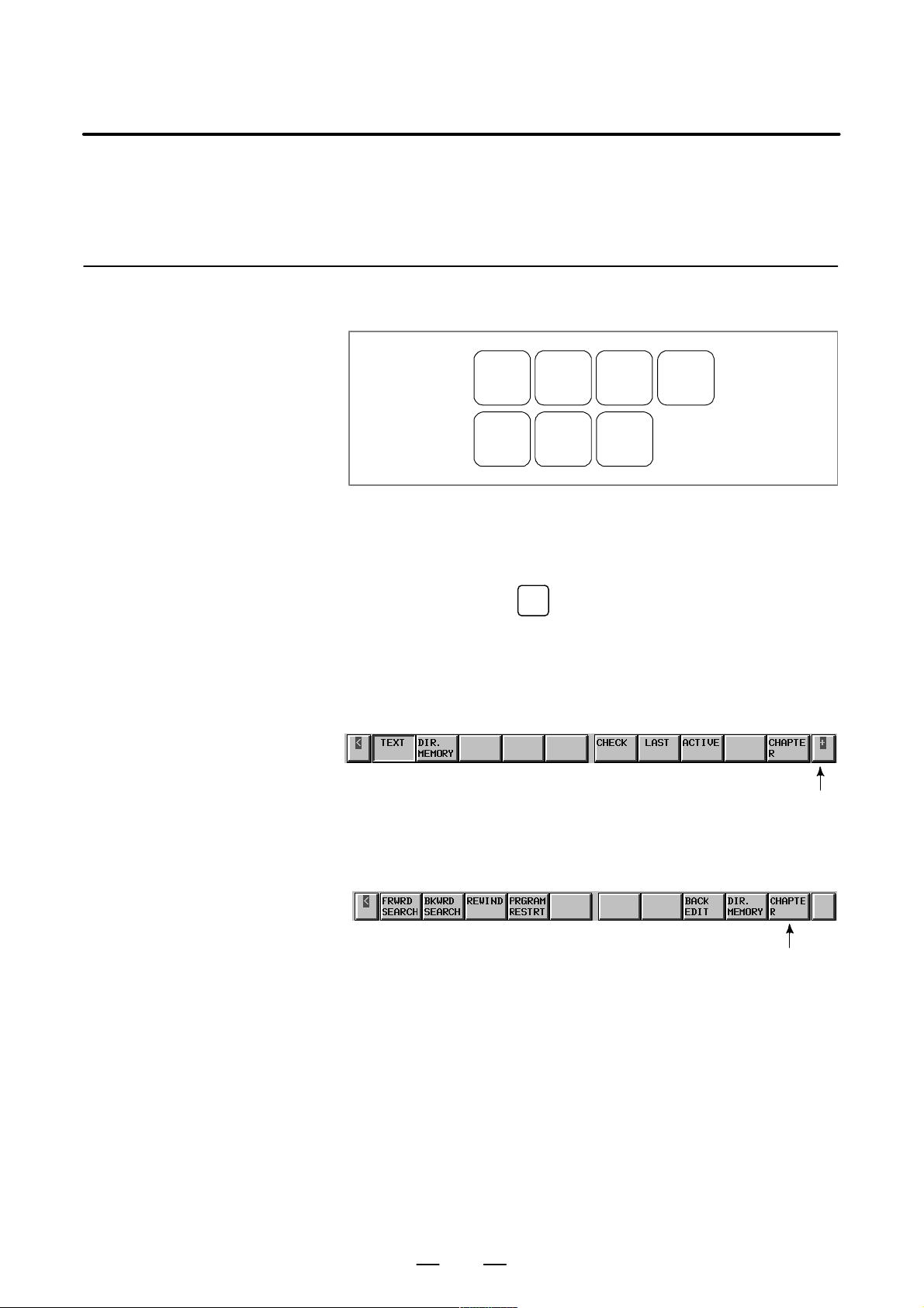
(1) Press a function key on the MDI panel to show the soft keys for
chapter selection related to the function.
POS PROG
SYSTEM
MESSAGE
OFFSET
SETTING
GRAPH
CUSTOM
(2) Press one of the indicated soft keys for chapter selection to display the
corresponding screen.
(3) Press an operation menu key to perform an operation on the displayed
chapter screen.
PROG
When you press the
key, for example, the following soft keys
for chapter selection are shown.
When the screen is first displayed, the first chapter is selected. (In this
example, “TEXT” is selected.)
To show an operation selection menu on this screen, press an
operation menu key at the rightmost position.
Operation menu key
(4) To return to the indications of the chapter–menu keys for chapter
selection while the operation selection menu is being displayed, press
the CHAPTER key.
CHAPTER key
The foregoing indication procedure is for general screens.
An actual indication procedure depends on each screen.
For specific operations, see each operation description.
2

B–63325EN/03
1. SCREEN INDICATIONS AND OPERATIONS
1.1.2
Types of Function Keys
POS
PROG
OFFSET
SETTING
SYSTEM
MESSAGE
GRAPH
Use a function key to select the corresponding function.
The following function keys are provided for the MDI panel.
Press this key to show an actual position screen.
Press this key to show a program screen.
Press this key to show an offset/setting screen.
Press this key to show a system screen.
Press this key to show a message screen.
Press this key to show a graphic screen.
1.1.3
Soft Keys
A screen can be selected with the corresponding soft key instead of the
corresponding function key.
Soft keys are also used to perform actual operations.
A function menu and a list of chapter selection menus are shown below .
NOTE
All soft keys described below are not necessarily shown.
Some soft keys are not shown according to a set option.
3
1. SCREEN INDICATIONS AND OPERATIONS
B–63325EN/03
1.1.4
Function Selection Keys
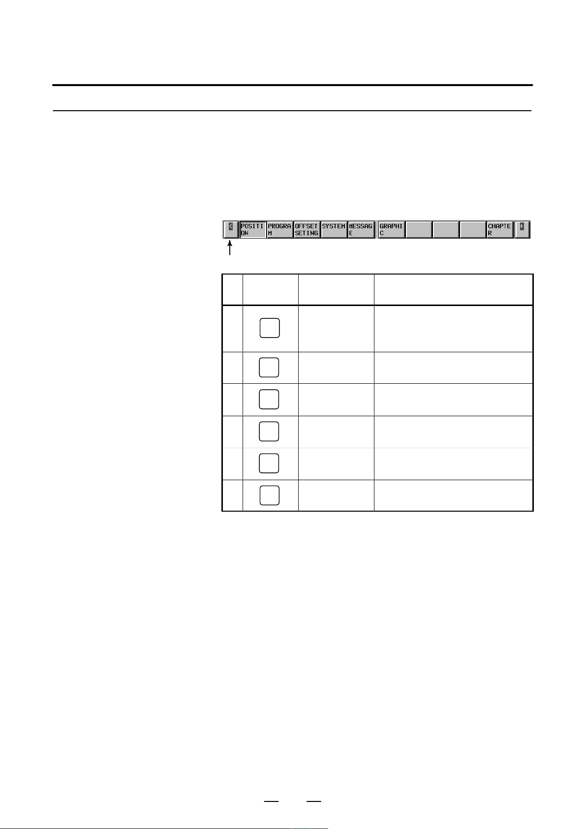
To select a function with the corresponding soft key, press the function
menu key first to set soft keys to a function selection key state, and then
press the desired function selection key.
Function selection is allowed in any mode.
Use a chapter selection key to specify detailed function selection.
The following function selection keys are provided.
(1) (2) (3) (4) (5) (6) (7) (8) (9) (10)
Function selection key
No.
(1)
(2)
(3)
Function key
(MDI panel)
POS
PROG
OFFSET
SETTING
Function selection
key (soft key)
POSITION Selects a current–position information
screen, including absolute coordinates, machine coordinates, relative coordinates, and
a remaining movement distance.
PROGRAM Selects a part program screen or a program
check screen.
OFFSETSETING Selects a tool offset screen or a workpiece
origin offset screen.
Description
(4)
(5)
(6)
SYSTEM
MESSAGE
GRAPH
SYSTEM Selects a parameter screen, a diagnosis
screen, or a PMC screen.
MESSAGE Selects a screen for alarm messages and
operator messages.
GRAPHIC Selects a graphic screen.
4
B–63325EN/03
1. SCREEN INDICATIONS AND OPERATIONS
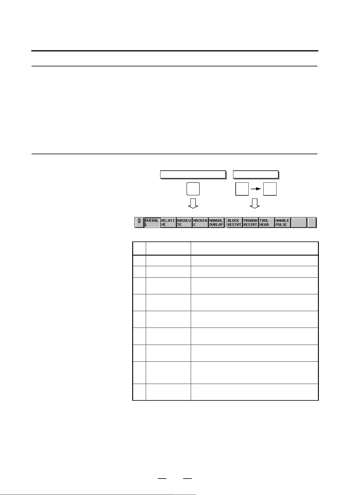
1.1.5
Chapter Selection Keys
1.1.5.1
Position
Use function selection keys to select items (functions).
Each item is further divided into subitems (chapters). Use a chapter
selection key to select the corresponding subitem (chapter).
To select a chapter, press the CHAPTER key to set the soft keys to a
chapter selection key state, and then press the desired chapter selection
key.
Alternatively, press a hardware function key repeatedly to change a
chapter selection.
The list of chapters included in each function is shown below.
Function key on the MDI panel
POS
(1) (2) (3) (4) (5) (6) (7) (8) (9) (10)
POSI-
TION
Soft keys
CHAP-
TER
No. Chapter menu Description
(1) OVERALL Selects an overall position indication screen.
(2) RELATIVE Selects a relative position indication screen.
(3) ABSOLUTE Selects a position indication screen in a workpiece coordi-
(4) MACHINE Selects a position indication screen in a machine coordinate
(5) MANUALOVRLAP Selects an operation screen for performing an operation with
(6) BLOCK RESTRT Selects an operation screen for restarting the operation from
(7) PROGRAM-
RESTRT
(8) TOOL HEAD Indicates the absolute coordinates and the actual speed of
(9) HANDLEPULSE Indicates a handle–pulse interruption amount in three–di-
nate system.
system.
manual handle interruption.
the suspended block.
Selects an operation screen for restarting the suspended
program operation.
the tool head in tool direction handle feed, tool normal direction handle feed, and rotational handle feed around tool tip.
mensional handle feed.
5
1. SCREEN INDICATIONS AND OPERATIONS
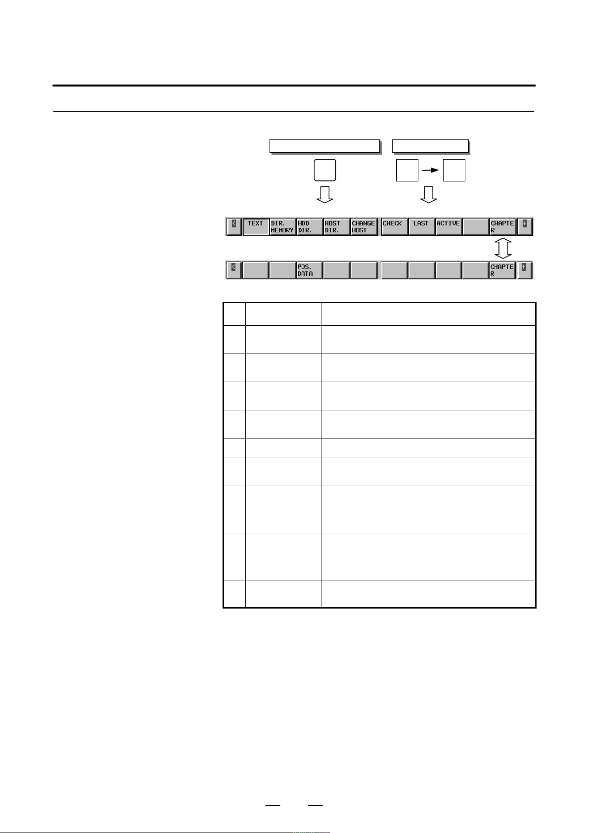
1.1.5.2
Program
Function key on the MDI panel
B–63325EN/03
Soft keys
PROG
(1) (2) (3) (4) (5) (6) (7) (8) (9) (10)
(11) (12) (13) (14) (15) (16) (17) (18) (19)
PRO-
GRAM
CHAP-
TER
No. Chapter menu Description
(1) TEXT Selects a screen for indicating the contents of the currently
(2) DIR. MEMORY Selects a screen for indicating the list of currently registered
(3) HDD DIR. Selects a screen for indicating the list of files stored in the
(4) HOST DIR. Selects a screen for indicating the list of files stored in the
(5) CHANGE HOST Selects a screen for changing connected host computer.
selected part program.
part programs.
hard disk on the data server.
host computer.
(6) CHECK Selects a screen for indicating a program, a position, and
(7) LAST Selects a screen for indicating a specified value in the last
(8) ACTIVE Selects a screen for indicating a specified value in the block
(13) POS. DAT A Selects a screen for indicating information related to position
modal information at the same time.
block currently being executed, and modal values such as
G codes and F codes specified until then, among specified
values.
currently being executed, and modal values such as G
codes and F codes specified until then, among specified
values.
compensation.
6
B–63325EN/03
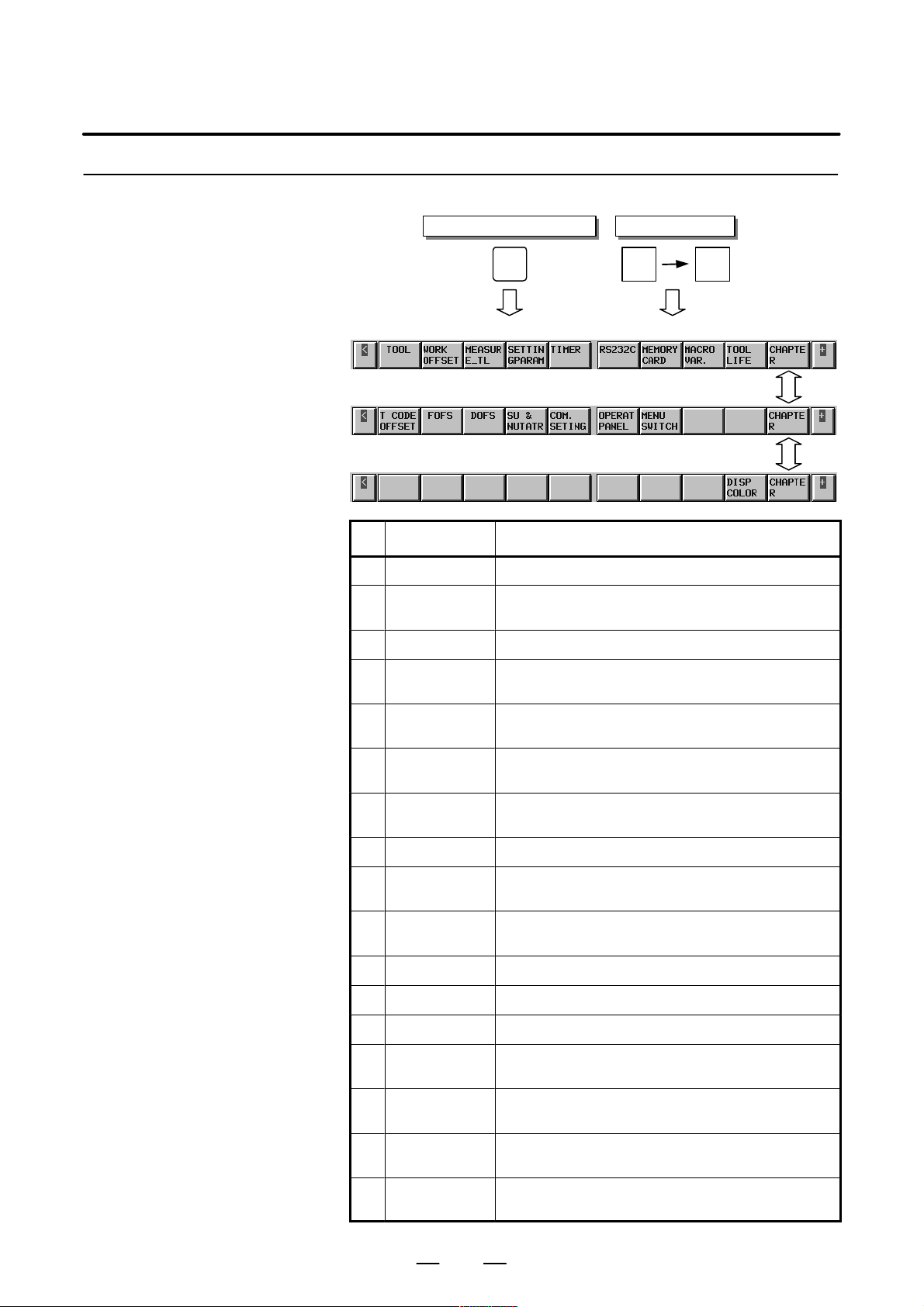
1.1.5.3
Offset/setting
1. SCREEN INDICATIONS AND OPERATIONS
Function key on the MDI panel
Soft keys
OFFSET
SETTING
OFFSET
SETTING
CHAP-
TER
(1) (2) (3) (4) (5) (6) (7) (8) (9) (10)
(11) (12) (13) (14) (15) (16) (17) (18) (19)
(21) (22) (23) (24) (25) (26) (27) (28) (29)
No. Chapter menu Description
(1) TOOL Selects a screen for setting a tool offset value.
(2) WORK OFFSET Selects a screen for setting an offset in the workpiece coordi-
(3) MEASURE_TL Selects a screen for measuring a tool length.
(4) SETTINGPARA-
METER
nate system.
Selects a screen for specifying setting parameters.
(5) TIMER Selects a screen for indicating information related to the num-
ber of machined parts and the operation time period.
(6) RS232C Selects a screen for operating a unit connected to the
RS–232C interface.
(7) MEMORYCARD Selects a screen for performing an operation related to a
memory card.
(8) MACRO VAR. Selects a screen for setting a macro variable.
(9) TOOL LIFE Selects a screen for performing a setting related to tool life
management.
(11) T CODEOFFSET Selects a screen for setting a tool number , a pot number , and
a tool offset value in tool offset by the tool number .
(12) FOFS Selects a fixture offset screen.
(13) DOFS Selects a dynamic tool offset screen.
(14) SU & NUTATR Selects an SU & NUTA TR of fset screen.
(15) COM. SETING Selects a screen for performing a setting related to RS 232C
and RS 422.
(16) OPERATPANEL Selects a screen for operating a part of the operation switches
on the machine operator’s panel as soft switches.
(17) MENU SWITCH Selects a screen for setting a part of input switch signals input
by a signal from the machine, in CNC operations.
(29) ETHERNET Selects a screen for performing a setting related to an Ether-
net board.
7
1. SCREEN INDICATIONS AND OPERATIONS
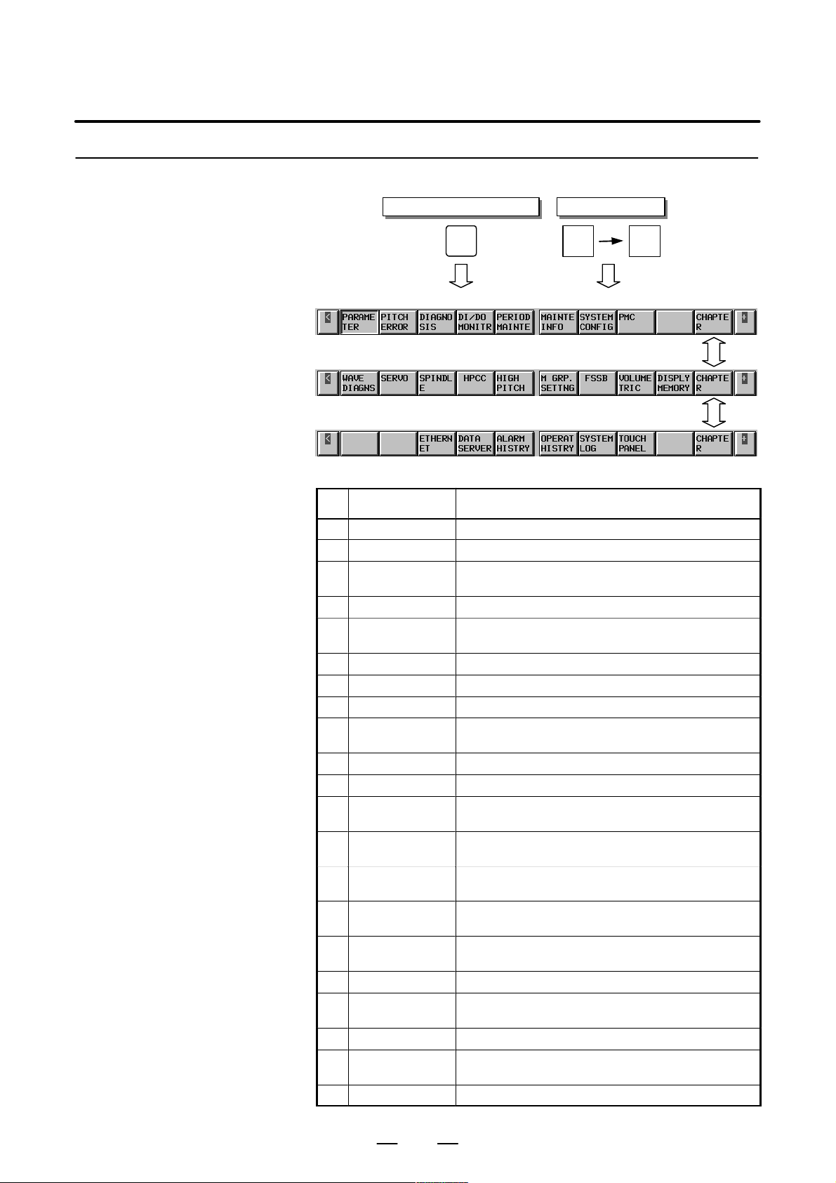
1.1.5.4
System
Function key on the MDI panel
B–63325EN/03
Soft keys
SYSTEM
(1) (2) (3) (4) (5) (6) (7) (8) (9) (10)
(11) (12) (13) (14) (15) (16) (17) (18) (19)
(21) (22) (23) (24) (25) (26) (27) (28) (29)
SYSTEM
CHAP-
TER
No. Chapter menu Description
(1) PARAMETER Selects a screen for setting a parameter .
(2) PITCH ERROR Selects a screen for setting pitch error compensation.
(3) DIAGNOSIS Selects a screen for showing information indicating a CNC
(4) DI/DO MONITOR Selects a screen for showing status information of signal.
(5) PERIODMAINTE Selects a screen for setting a maintenance item to be peri-
(6) MAINTEINFO Selects a screen for setting information in maintenance.
(7) SYSTEMCONFIG Selects a screen for showing the current system state.
(8) PMC Selects a screen related to PMC.
(11) WA VE DIAGNS Selects a screen for showing data, such as a servo position
(12) SERVO Selects a screen for performing servo setting.
(13) SPINDLE Selects a screen for performing spindle setting.
(14) HPCC Selects a screen for performing a setting related to high–
(17) FSSB Selects a screen for performing a setting related to a high–
(18) VOLUMETRIC Selects a screen for setting three–dimensional error com-
(19) DISPLYMEMORY Selects a screen for showing the contents of the current
(23) ETHERNET Selects a screen for maintenance and setting of the Ether-
(24) DATA SERVER Selects the screen for Data server maintenance and setting.
(25) ALARM HISTRY Selects a screen for showing the contents of a previously
(26) OPERAT HISTORY Selects a screen for showing operation history.
(27) SYSTEMLOG Selects a screen for showing the contents of a previously
(28) TOUCH PANEL Selects a screen for setting a touch panel.
state.
odically controlled.
error , torque, and a machine signal, in a graph.
precision contour control.
speed serial bus (FSSB: Fanuc serial servo bus).
pensation.
CNC memory.
net board.
generated alarm.
generated system alarm.
8
B–63325EN/03
1.1.5.5
Messages
1. SCREEN INDICATIONS AND OPERATIONS
Function key on the MDI panel
Soft keys
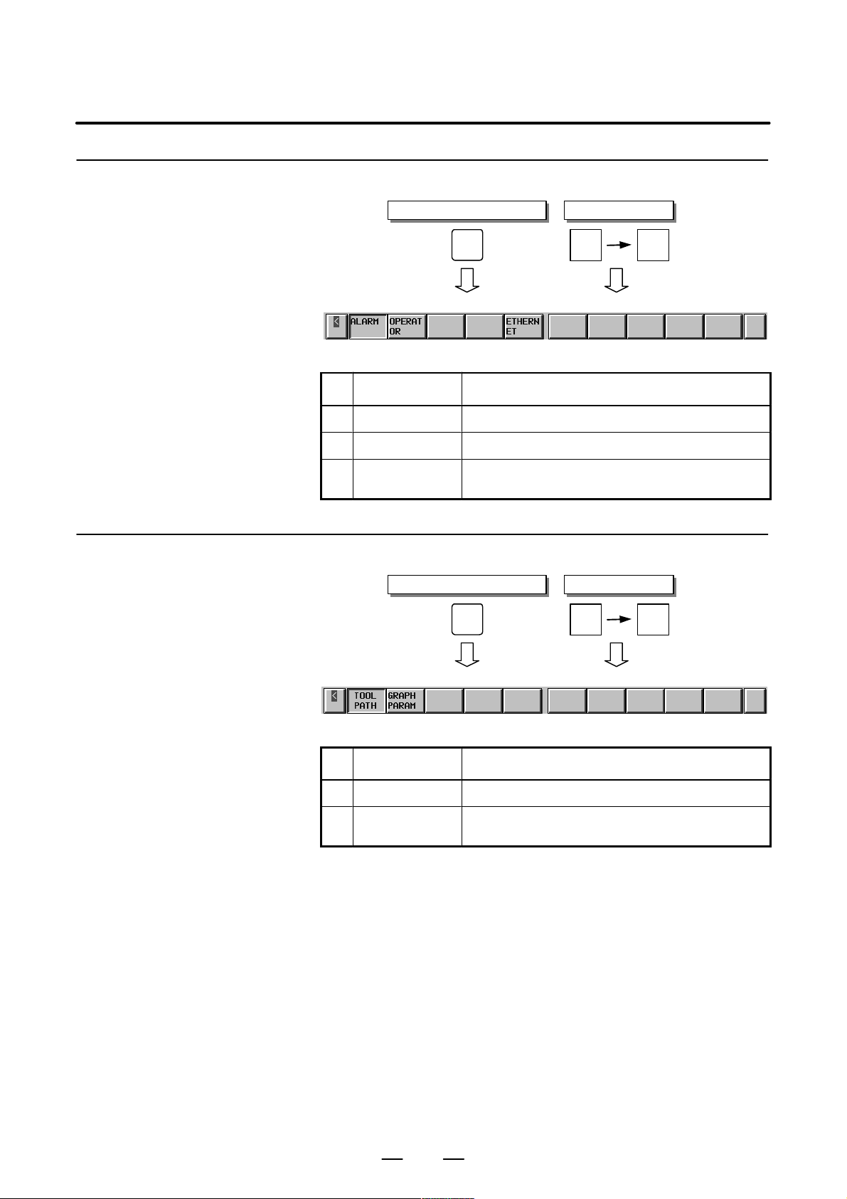
1.1.5.6
Drawing
MES-
SAGE
(1) (2) (3) (4) (5) (6) (7) (8) (9) (10)
MES-
SAGE
CHAP-
TER
No. Chapter menu Description
(1) ALARM Selects an alarm message screen.
(2) OPERATOR Selects an operator message screen.
(5) ETHERNET Selects a screen for showing logging information on Ether-
Function key on the MDI panel
net board.
GRAPH
GRAP-
HIC
Soft keys
CHAP-
TER
(1) (2) (3) (4) (5) (6) (7) (8) (9) (10)
No. Chapter menu Description
(1) TOOL PATH Selects a screen for graphic indication of a tool path.
(2) GRAPH PARAM Selects a screen for performing a setting of tool–path draw-
ing.
9

1. SCREEN INDICATIONS AND OPERATIONS
B–63325EN/03
1.2
SCREEN INDICATIONS A T POWER ON
The test results of hardware (RAM and ROM), and the check results of
control software and file data are indicated on the screen at power on.
FANUC SERIES 15I F010A
COPYRIGHT(C) FANUC LTD 1997–1999
RAM TEST : END
ROM TEST : END
PMC ROM TEST : END
SERVO RAM TEST : END
SERVO ROM TEST : END
LOAD SYSTEM LABEL : END
CHECK SYSTEM LABEL : END
LOAD FILES : END
LOAD MESSAGE DATA : END
CAUTION
If a hardware error is detected in the RAM and ROM tests
for the CNC, PMC, and digital servo system, power–on
processing is stopped.
Series and edition of
CNC control software
Copyright indication
Test results of RAM and
ROM mounted on CNC,
PMC, and digital servo
system
Verification result of
compatibility of CNC
control software
Loading results of
backup file data such as
NC parameters, and
language data
10

B–63325EN/03
1. SCREEN INDICATIONS AND OPERATIONS
1.3
DIAGNOSIS FUNCTION
D Cause for not operating
even if a command is
given
1000 Internal CNC state 1
If an error occurs, or if a machine operation stops for some reason such
as an external–signal wait state without an error and it seems as if an error
occurs, it is necessary to check the cause from the internal CNC state and
an interface state between the CNC and PMC or between the CNC and the
machine.
The CNC performs various checks during its operation.
1.Detection–system error
2.Position–control–section error
3.Serve–system error
4.Overheat
5.CPU error
6.ROM error
7.RAM error
8.Program–memory error
9.Data–input error
10.Error in data transfer with PMC
In addition, an internal CNC state is checked. The state can be shown on
the screen.
[Data type] Bit type
[Unit of data] None
Name Internal state when “1” is indicated
Imposition Check The imposition check is being performed.
Feedrate Override 0% The feedrate override is 0%.
Jog Feed Override 0% The jog feedrate override is 0%.
Inter/Start Lock on The interlock/start lock is on.
Speed Arrival on It is being awaited that the speed arrival
signal is turned on.
Wait Revolution The spindle one–revolution signal is
awaited in threading.
Stop Position Coder It is awaited that the position coder rotates
in spindle feed per revolution.
Feed Stop The feed stop is being performed.
1001 Internal CNC state 2
[Data type] Bit type
[Unit of data] None
Name Internal state when “1” is indicated
Foreground Reading Foreground data is being input.
Background Reading Background data is being input.
11

1. SCREEN INDICATIONS AND OPERATIONS
D Cause for not starting
#7
1005
#6 #5 #4 #3 #2
Bit Name Internal state when “1” is indicated
#0 JMD DI and DO signals are incorrect in a manual
#1 RPO DI and DO signals are incorrect in repositioning
#2 OTH Others (*3).
B–63325EN/03
OTH#1RPO#0JMD
numeric command (*1).
for tool retraction and recovery (*2).
#7
RVS1006
#6
PTR
#5
MDI
#4
NOP#3EDT
#2
SRN#1ALM
#0
*SP
Bit Name Internal state when “1” is indicated
#0 *SP The automatic–operation stop signal (*SP) is “0.”
#1 ALM An alarm is generated.
#2 SRN The SRN signal or the BRN signal is “1.”
#3 EDT An attempt was made to execute a program being
background edited.
#4 NOP The device is not ready in the DNC mode.
#5 MDI The contents which the MDI executed is
remaining.
#6 PTR The tool retraction signal (TRESC) is “1.”
Alternatively, the tool is not returned to the
position where the tool retraction signal was input.
#7 RVS Reverse operation of the program cannot be
performed.
If a bit becomes “1,” remove the cause and then restart.
Multiple bits cannot become “1.” Even if multiple causes happen, the bit
corresponding to the last cause becomes “1.”
NOTE
1 The DEN signal or the IPEN signal of DO is “1.”
Constant surface speed control is being executed.
The state of HEAD1/2 of DI is wrong in the MDI mode (only
for TT series).
2 The OP signal of DO is “0” in a repositioning operation of tool
retraction and recovery.
The MLK signal of DI is “1.”
The STL signal of DO is “1.”
3 A retraction operation is being performed in the hobbing
machine.
In the bed grinding machine, an alarm is being generated
or the MLK signal of DI is “1.”
The axis to be jog retracted is at a position where movement
cannot be started.
12

B–63325EN/03
1. SCREEN INDICATIONS AND OPERATIONS
D Alarm classification
1007
1008
The diagnostic data 1007 and 1008 indicates classification information of
a generated alarm. When the alarm is released, the data becomes “0.”
#7
#6 #5
PW
#4
IO
#3
PC
#2
OT
#1
SV
#0
SW
Bit Name Internal state when “1” is indicated
#0 SW Parameter writing switch on
#1 SV Servo alarm
#2 OT Overtravel
#3 PC PMC error
#4 IO I/O error
#5 PW Input of parameter which requires power off
#6 (Not used)
#7 (Not used)
#7
#6 #5 #4 #3 #2
SR
#1
BG
#0
PS
Bit Name Internal state when “1” is indicated
#0 PS Program operation alarm
#1 BG Background editing alarm
#2 SR Severe program–operation alarm
#3 (Not used)
#4 (Not used)
#5 (Not used)
#6 (Not used)
#7 (Not used)
D Warning state
1009
D Reset/feed hold state
1010
#7
#6 #5 #4 #3 #2 #1 #0
Bit Name Internal state when “1” is indicated
#0 WRN A warning is generated.
When the warning is released, the data becomes “0.”
#7
#6 #5 #4 #3
RST
#2
ERS#1RRW#0ESP
Bit Name Internal state when “1” is indicated
#0 ESP During emergency stop
#1 RRW The reset and rewind signal is “1.”
#2 ERS The external reset signal is “1.”
#3 RST The reset key is being pressed.
13
WRN

1. SCREEN INDICATIONS AND OPERATIONS
D Cause of turning off of
the cycle start lamp
#7
HLD1011
#6
STP#5MOD#4ALM
Bit Name Internal state when “1” is indicated
#0 ESP During emergency stop
#1 RRW The reset and rewind signal is “1.”
#2 ERS The external reset signal is “1.”
#3 RST The reset key is being pressed.
#4 ALM An alarm is being generated.
#5 MOD The mode has been changed to another mode.
#6 STP Single–block stop
#7 HLD During feed hold
#3
RST
B–63325EN/03
#2
ERS#1RRW#0ESP
D TH alarm state
The diagnostic data 1100 to 1111 indicates the state of a TH alarm.
1100 Position of character where a TH alarm was generated (foreground)
[Data type] Integer type
[Unit of data] None
The position of a character where a TH alarm was generated in foreground
input is indicated by the number of characters from the top of the block.
1101 Code of character which caused a TH alarm (foreground)
[Data type] Bit type
[Unit of data] None
The bit pattern of the character which caused a TH alarm in foreground
input is indicated.
1110 Position of character where a TH alarm was generated (background)
[Data type] Integer type
[Unit of data] None
The position of a character where a TH alarm was generated in
background input is indicated by the number of characters from the top
of the block.
1111 Code of character which caused a TH alarm (background)
[Data type] Bit type
[Unit of data] None
The bit pattern of the character which caused a TH alarm in background
input is indicated.
14

B–63325EN/03
1. SCREEN INDICATIONS AND OPERATIONS
D Serial spindle
The diagnostic data 1500 to 1505 indicates serial–spindle information.
#7
SALMI1500
#6 #5
CALM#4CMER#3CER#2SNER#1FRER#0CRER
[Data type] Bit spindle type
Bit Name Internal state when “1” is indicated
#0 CRER A CRC error occurred (warning).
#1 FRER A framing error occurred (warning).
#2 SNER A transmission/receiving mate is wrong.
#3 CER A receiving error occurred.
#4 CMER A return is not received during automatic
scanning.
#5 CALM A communication alarm was generated in the
spindle amplifier.
#6 (Not used)
#7 SALMI A system alarm was generated in the spindle
amplifier.
1504 T orque data of spindle motor
[Data type] Integer spindle type
[Unit of data] %
1505 Speed data of spindle motor
[Data type] Integer spindle type
[Unit of data] min
D Servo position error
3000 Servo position error
[Data type] Integer axis type
[Unit of data] Detection unit
3001 Servo position error amount + F AD error amount
[Data type] Integer axis number
[Unit of data] Detection unit
–1
Displays the sum of the servo position error and the number of FAD
accumulated pulses if fine acceleration/deceleration (FAD) is used.
15

1. SCREEN INDICATIONS AND OPERATIONS
D Reference position
return
B–63325EN/03
[Unit of data] Detection unit
D Servo control
information
D Digital servo alarm
3008
Distance from the position where the deceleration dog is released to the
first grid position
[Data type] Integer axis type
The distance from the position where the deceleration dog is released to
the first grid position is indicated in the reference position shift function.
Number Description of indicated data
3010 to 3023
3030 to 3043
3050 to 3063
3070 to 3083
3090 to 3103
31 10 to 3123
3130 to 3143
3150 to 3163
3170 to 3183
The diagnostic data 3014 and 3015 indicates alarm information when an
alarm is generated in digital servo.
#7
OVL3014
#6
LVAL#5OVC#4HCAL#3HVAL#2DCAL#1FBAL#0OFAL
Servo control information of first axis
Servo control information of second axis
Servo control information of third axis
Servo control information of fourth axis
Servo control information of fifth axis
Servo control information of sixth axis
Servo control information of seventh axis
Servo control information of eighth axis
Servo control information of ninth axis
First axis: 3014
Second axis: 3034
Third axis: 3054
(The subsequent axes correspond to data numbers each increased by 20
in that order.)
Bit Name Internal state when “1” is indicated
#0 OFAL An overflow alarm is being generated inside the
digital servo.
#1 FBAL A pulse–coder disconnection alarm is being
generated.
#2 DCAL A regenerative discharge circuit alarm is being
generated in the servo amplifier (the “DC” LED of
the servo amplifier is on).
#3 HVAL An overvoltage alarm is being generated in the
servo amplifier (the “HV” LED of the servo
amplifier is on).
#4 HCAL An abnormal current alarm is being generated in
the servo amplifier (the “HC” LED of the servo
amplifier is on).
#5 OVC An overcurrent (overload) alarm is being
generated in the servo amplifier.
#6 LVAL A low voltage alarm is being generated in the servo
amplifier (the “LV” LED of the servo amplifier is
on).
16

B–63325EN/03
1. SCREEN INDICATIONS AND OPERATIONS
#7 OVL An overload alarm is being generated in the servo
motor or the servo amplifier. If the alarm is
generated in the servo amplifier, overheat occurs
in the servo amplifier, the separate discharge unit,
or the power transformer (the “OH” LED of the
servo amplifier is on).
#7
ALDF3015
#6 #5 #4
EXPC
#3 #2 #1 #0
First axis: 3015
Second axis: 3035
Third axis: 3055
(The subsequent axes correspond to data numbers each increased by 20
in that order.)
D Identification of disconnection alarms and overload alarms
Disconnection alarms and overload alarms can be identified as shown
in the following table by the diagnostic data 3014 and 3015.
Alarm type 3014#7
OVL
Overheat 1 0 1 0
Amplifier overheat 1 0 0 0
Disconnection (hardware) of built–in
pulse coder
Disconnection (hardware) of sepa-
rate pulse coder
Disconnection (software) of pulse
coder
0 1 1 0
0 1 1 1
0 1 0 0
3014#1
FBAL
3015#7
ALDF
3015#4
EXPC
D Absolute position
detection alarm
If an SV101 data error alarm (ABS PCDR) or an OT032 reference
position return alarm (ABS PCDR) is generated, the contents of the alarm
are indicated.
#7
APMVAL3018
#6
APPER#5APFER#4APTER#3APCER#2APBATZ#1APPLSM#0APNZRN
First axis: 3018
Second axis: 3038
Third axis: 3058
(The subsequent axes correspond to data numbers each increased by 20
in that order.)
Bit Name Internal state when “1” is indicated
#0 APNZRN The reference position does not correspond to the
value of the absolute–position detection counter.
(Action: Make correspondence between the
reference position and the absolute–position
detection.)
#1 APPLSM A pulse error alarm was generated. (Action: Make
correspondence between the reference position
and the absolute–position detection.)
17

1. SCREEN INDICATIONS AND OPERATIONS
#2 APBATZ The battery voltage of the absolute–position
#3 APCER A communication error occurred during data
#4 APTER A time over error occurred during data
#5 APFER A framing error occurred during data
#6 APPER A parity error occurred during data transmission.
#7 APMVAL An excessive motor displacement alarm was
B–63325EN/03
detector became 0. (Action: Replace the battery
and make correspondence between the reference
position and the absolute–position detection.)
transmission. (Action: Replace the pulse coder.)
transmission. (Action: Replace the pulse coder.)
transmission. (Action: Replace the pulse coder.)
(Action: Replace the pulse coder.)
generated. It is generated when the machine
moves largely at power on and the pulse count in
detection units exceeds 24,000. (Action: Take a
measure in the machine so that the machine does
not move at power on.)
D HIGH SPEED HRV status
3022
D Servo synchronization
error
#7
#6 #5 #4 #3 #2 #1
ERVOK#0HRVON
First axis: 3022
Second axis: 3042
Third axis: 3062
(n–th axis: 3022 + 20 x (n – 1)
Bit Name Internal status assumed when “1” is displayed
#0 HRVON The motor is controlled in HIGH SPEED HRV
mode.
#1 HRVOK When the parameter HR3 (No.1707#0) is set to
“1”, HIGH SPEED HR V is enabled (as determined
with the status of the servo software, servo control
card, servo amplifier, and Separate Detector I/F
Unit).
3500 Amount of servo synchronization error
[Data type] Integer axis type
[Unit of data] Detection unit
The positional difference (the amount of synchronization error) between
the master axis and the slave axis in synchronization control is indicated.
It is indicated at the location corresponding to the axis number of the slave
axis.
18

B–63325EN/03
3501 Amount of servo synchronization error compensation
[Data type] Integer axis type
[Unit of data] Detection unit
D Dual position feedback
3510 Error amount of dual position feedback
[Data type] Integer axis type
[Unit of data] Detection unit
1. SCREEN INDICATIONS AND OPERATIONS
The accumulated value (the amount of synchronization error
compensation) of the compensation pulses output to the slave axis in
synchronization control is indicated.
It is indicated at the location corresponding to the axis number of the slave
axis.
The difference (the positional difference between the machine and the
motor) between the feedback of the closed loop and the feedback of the
semi–closed loop is indicated.
3511 Sum of compensation amounts in dual position feedback
[Data type] Integer axis type
[Unit of data] Detection unit
The sum of the output compensation pulses in dual position feedback is
indicated.
3512 Error counter in the closed loop
[Data type] Integer axis type
[Unit of data] Detection unit
3513 Error counter in the semi–closed loop
[Data type] Integer axis type
[Unit of data] Detection unit
Data items indicated on the diagnosis screen correspond to the following
locations.
19

1. SCREEN INDICATIONS AND OPERATIONS
Semi–closed–
loop error
(No. 3513)
B–63325EN/03
Command
++
–
Ps
Closed–loop
error (No. 3512)
+
–
S
S
+
D Three–dimensional error
compensation
Kp
+
–
Closed–loop–
semi–closed–loop
error (No. 3510)
+
–
(Parameters No. 1971 and No. 1972)
+
+
Speed
control
Servo amplifier
Conversion
coefficient
X time
constant
Parameter No. 1973
Motor
Machine
Dual position compensation amount
(No. 3511)
3530 Three–dimensional error compensation amount
[Unit of data] Detection unit
D OVC level
3540 OVC level
D Absolute–position
detection in Inductosyn
method
3700
[Unit of data] Detection unit
[Data type] Integer axis type
[Data type] %
[Meaning] The ratio of the soft thermal (OVC) level to the alarm generation level is
indicated.
Shift between the motor absolute position and the offset data in the absolute–position detection function with the Inductosyn method
[Data type] Integer axis type
The remainder of (motor absolute position – offset data)/(one–pitch
interval) is indicated.
20

B–63325EN/03
1. SCREEN INDICATIONS AND OPERATIONS
3701
[Data type] Integer axis type
[Unit of data] Detection unit
D Coordinate related data
4100 Shift to the coordinate system by manual operation
[Data type] Real–number axis type
[Unit of data] Input unit
4101
[Data type] Real–number axis type
Offset data from the Inductosyn in the absolute–position detection function
with the Inductosyn method
The offset data which the CNC received at machine–position calculation
is indicated.
The movement distance along each axis by manual operation in a case in
which the manual absolute signal is “0” is indicated.
Amount of intervention by manual interruption in simultaneous automatic
and manual operations
[Unit of data] Input unit
The amount of intervention by manual interruption for each axis is
indicated.
4102 Offset to the coordinate system by G92 workpiece coordinate system setting
[Data type] Real–number axis type
[Unit of data] Input unit
The offset to the coordinate system by a G92 command for each axis is
indicated.
4103 Offset to the coordinate system by G52 local coordinate system setting
[Data type] Real–number axis type
[Unit of data] Input unit
The offset to the coordinate system by a G52 command for each axis is
indicated.
4104 Shift to the coordinate system in a machine lock state
[Data type] Real–number axis type
[Unit of data] Input unit
The shift to the coordinate system by a move command in a machine lock
state for each axis is indicated.
21

1. SCREEN INDICATIONS AND OPERATIONS
1.4
CNC STATE INDICATIONS
(1) Automatic–operation mode selection
The selected operation mode in automatic operation is indicated.
MDI: MDI operation
MEM: Memory operation
DNC: DNC operation
EDIT: Memory editing
****:Automatic operation is not selected.
(2) Manual–operation mode selection
The selected operation mode in manual operation is indicated.
JOG: Jog feed
REF: Manual reference position return
HND: Manual handle feed
INC: Incremental feed
AGJ: Manual desired–angle feed
J+H: Jog feed + manual handle feed
I+H: Incremental feed + manual handle feed
****: Manual operation is not selected.
(1)
(2)
(3)
B–63325EN/03
(4)
(3) Automatic–operation state
The state of automatic operation is indicated.
RSET: Being reset
STOP: Automatic–operation stop state
HOLD:Automatic–operation hold state
STRT: Automatic–operation start state
MSTR:Manual–numeric–command start state
NSRC: Sequence number being searched for
22

B–63325EN/03
1. SCREEN INDICATIONS AND OPERATIONS
(4) Program–editing state
The state of program editing is indicated.
READ:Being registered
PNCH:Program being output
VRFY: Being verified
SRCH: Being searched for
COND: Memory being rearranged
EDIT: Being edited in another way (such as INSERT or ALTER)
****:Editing is not performed.
(5) (6) (7)
(5) State of movement along axis, dwell, or emergency stop
The state of movement along axis, dwell, or emergency stop is
indicated.
MTN: Being moved along the axis
DWL: During dwell
EMG: During emergency stop
***: None of the above states
(6) MSTB state
Whether a miscellaneous function such as MSTB is being executed
is indicated.
FIN: Miscellaneous function such as MSTB being executed (waiting
for a completion signal from the PMC)
***: Miscellaneous function such as MSTB not being executed
(7) Alarm state and label–skip state
The state of an alarm, a warning, the battery, or a label skip is
indicated.
ALM : Alarm being generated (reverse indication and blinking)
WRN : Warning message being indicated
(reverse indication and blinking)
BAT : Battery life nearly running out
(reverse indication and blinking)
LSK:Label–skip state in data input
(blank): None of the above states
23

1. SCREEN INDICATIONS AND OPERATIONS
B–63325EN/03
1.5
WAVEFORM DIAGNOSIS FUNCTION
This function traces data such as a servo position error, torque, and a
machine signal and shows a change in the data as a waveform. This
facilitates the adjustment of a servo motor and a spindle motor and finding
of a possible cause in a problem.
This function traces the following data.
(1) Servo–related items
Position error of a servo motor along each axis, pulse count after
distribution, torque, pulse count after acceleration and deceleration,
actual speed, specified current, and thermal simulation data
(2) Combined speed for all axes
(3) Spindle–related items
Spindle–motor speed and load meter indication
(4) State of on (“1”)/off (“0”) of machine signal
A total of four items among the servo–related items, the combined speed
for all axes, and the spindle–related items, and four machine signals can
be traced at a time.
The waveforms of all traced data items can be displayed at the same time.
Tracing can be performed by the following three conditions.
(1) Data at a predetermined timing
(2) Data immediately after the specified event occurs
(3) Data immediately before the specified event occurs
Traced data can be output to an external input and output unit. Output data
can also be read.
24

B–63325EN/03
1. SCREEN INDICATIONS AND OPERATIONS
Waveform–diagnosis
graphic screen
D Waveform–diagnosis
graphic screen
Display the waveform–diagnosis graphic screen according to the
procedure described in II 2.6 Soft Keys in the FANUC Series
15i/150i–MA Operator’s Manual (Operation) (B–63324EN–1).
The wave–form diagnosis graphic screen provides data tracing operations
and the waveform indications of traced data.
Fig. 1.5 (a) Waveform–diagnosis graphic screen
The waveforms of a total of four items among the servo–related items, the
combined speed for all axes, and the spindle–related items are drawn with
colors specified for the items.
At the left–hand side of the screen, the graduations of the first waveform
and the second waveform are indicated by the same colors as for the
waveforms. At the right–hand side of the screen, the graduations of the
third waveform and the fourth waveform are indicated in the same way.
The addresses of traced machine signals are indicated at the right–hand
side of the screen. The waveforms of the machine signals are drawn in
white.
The tracing start time and the tracing end time of traced data are indicated
at the top of the screen. While data is being traced, a message of “Tracing”
is indicated.
25

1. SCREEN INDICATIONS AND OPERATIONS
B–63325EN/03
Waveform–diagnosis
parameter screen
D Page 1 of
waveform–diagnosis
parameter screen
Press the [PARAMETER] soft key on the waveform–diagnosis graphic
screen to show the waveform–diagnosis parameter screen.
The waveform–diagnosis parameter screen provides the settings of
various parameters related to data tracing and waveform indications.
The waveform–diagnosis parameter screen has three pages.
Fig. 1.5 (b) Waveform–diagnosis parameter screen (Page 1)
On Page 1 of the waveform–diagnosis parameter screen, set parameters
common to the entire diagnosis, such as a tracing condition, a trigger
event, and a tracing time.
Also set the addresses of machine signals to be traced, on Page 1.
26

B–63325EN/03
D Page 2 of
waveform–diagnosis
parameter screen
1. SCREEN INDICATIONS AND OPERATIONS
Waveform–diagnosis
parameters
D TRACE CONDITION
Fig. 1.5 (c) Waveform–Diagnosis Parameter Screen (Page 2)
On Page 2 of the waveform–diagnosis parameter screen, set each
parameter related to the first waveform and the second waveform.
At the right half of the screen, the types of trace data and waveform–color
numbers are indicated as lists.
On Page 3 of the waveform–diagnosis parameter screen, perform the
same settings for the third waveform and the fourth waveform.
Waveform–diagnosis parameters are required to be set on the
waveform–diagnosis parameter screen in order to trace data.
One of the following three conditions can be selected according to a
condition for tracing start/end.
TYPE 1: Traces data for the specified time period from when the
[TRACE] soft key is pressed.
Tracing period
Time
[TRACE] key pressed
TYPE 2: Traces data for the specified time period from when the
specified trigger event occurs after the [TRACE] soft key is
pressed.
Tracing period
Time
[TRACE] key pressed
27
Event occurs
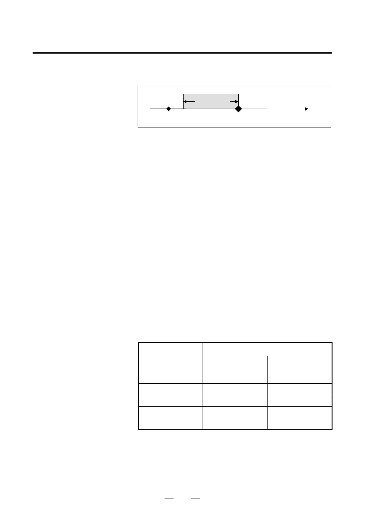
1. SCREEN INDICATIONS AND OPERATIONS
TYPE 3: Traces data for the specified time period until the specified
[TRACE] key pressed
B–63325EN/03
trigger event occurs after the [TRACE] soft key is pressed.
Tracing period
Time
Event occurs
D TRIGGER EVENT
Set a trigger event for the type–2 or type–3 tracing condition.
In the type–2 tracing condition, when the specified trigger event occurs,
tracing starts. In the type–3 tracing condition, tracing ends when the
specified trigger event occurs.
SERVO ALARM
Specify whether a servo alarm serves as a trigger event.
VALID: A servo alarm serves as a trigger event.
INVALID: A servo alarm does not serve as a trigger event.
DI/DO SIGNAL
Specify whether the specified machine signal serves as a trigger event.
ON: An ON transition of the specified machine signal serves as a
trigger event.
OFF: An OFF transition of the specified machine signal serves as a
trigger event.
CHANGE: A change of the specified machine signal serves as a
trigger event.
INVALID: A machine signal does not serve as a trigger event.
DI/DO SIGNAL ADDRESS
Set the address of the machine signal when the machine–signal setting
above is ON, OFF, or CHANGE.
D TRACE TIME
Set the data tracing period in a range of 10 ms to 80000 ms.
A tracing cycle is determined according to the tracing period as shown
below.
Tracing cycle
Tracing period
10 to 10000ms 2ms 8ms
to 20000ms 4ms 8ms
to 40000ms 8ms 8ms
to 80000ms 16ms 16ms
Servo–related items,
combined speed, and
spindle–related items
Machine signal
28

B–63325EN/03
1. SCREEN INDICATIONS AND OPERATIONS
D DELAY TIME
In the type–3 tracing condition, the tracing end time can be delayed by the
specified time period after the event occurs. Set the time period in a range
of 0 ms to 160000 ms.
(1) Delay period of 0
Tracing period
Time
[TRACE] key pressed
Event occurs
(2) 0 < delay period < tracing period
Data is traced before and after the event occurs.
Tracing period
Delay
[TRACE] key pressed
period
Event occurs
Time
(3) Delay period = tracing period
Tracing starts when the event occurs (equivalent to type 2)
Tracing period
= delay period
[TRACE] key pressed
Event occurs
(4) Delay period > tracing period
Tracing starts when a time elapses after the event occurs.
Tracing period
Delay period
[TRACE] key pressed
Event occurs
Time
Time
29

1. SCREEN INDICATIONS AND OPERATIONS
B–63325EN/03
D TRACE DATA TYPE
Specify the number of the data to be traced.
Data number Type Unit
0 No tracing
1 Servo position error Pulse (detection unit)
2 Servo pulse count after distribution Pulse (detection unit)
3 Servo torque %
4 Servo pulse count after acceleration and
deceleration
5 Servo actual speed Pulse (detection unit)
6 Specified servo current %
7 Thermal–simulation data of servo %
8 Combined speed for all axes MM/MIN,INCH/MIN,RPM
9 Spindle speed min
10 Spindle load meter %
Pulse (detection unit)
–1
NOTE
1 The combined speed for all axes does not include the speed
along the axis which is excluded by the DI signal *ACTF for
axis selection in actual speed indications.
2 The servo torque and the specified servo current are
indicated in percentage (%) of the parameter values (No.
1979)
D AXIS ASSIGN
Specify an axis number according to the type of the data to be traced, as
shown below.
Data number Type Axis number
1 Servo position error
2 Servo pulse count after distribution
3 Servo torque
4 Servo pulse count after acceleration and
deceleration
5 Servo actual speed
6 Specified servo current
7 Thermal–simulation data of servo
8 Combined speed for all axes Head number (1 or great-
9 Spindle speed
10 Spindle load meter
30
Servo axis number (1 or
greater)
er), specify in TT series
Spindle number (1 or
greater)

B–63325EN/03
1. SCREEN INDICATIONS AND OPERATIONS
D HORIZON.GRADUATION
D VERTICAL GRADUATION
D DI/DO SIGNAL
D WAVE COLOR
Setting
waveform–diagnosis
parameters
Specify a graduation of the horizontal axis (time axis) in a range of 25 ms
to 800 ms.
Specify a graduation of the vertical axis in a range of 1 to 500000 for each
trace data. Set this parameter for servo–related items, the combined speed
for all axes, and spindle–related items.
When the on (“1”)/off (“0”) state of a machine signal is traced, specify the
address of the machine signal. Up to four machine signals can be
specified. If no trace is made, input “0.”
Specify a waveform color for each data to be traced as shown below.
0: White 1: Red 2: Green 3: Yellow
4: Blue 5: Purple 6: Light blue 7: White
This parameter is effective for the waveform of each data of the
servo–related items, the combined speed for all axes, and the
spindle–related items. The waveform of the on (“1”)/off (“0”) state of a
machine signal is drawn in white.
D Moving the cursor
D Inputting a setting
Use the page keys
PAGE
and
and cursor keys and to move
PAGE
the cursor to the parameter to be set.
In setting “TRACE CONDITION,” “TRIGGER EVENT – SERVO
ALARM,” and “TRIGGER EVENT – DI/DO Signal” on Page 1, use
cursor keys
and to move the cursor in order to select the
desired settings.
Method 1
(1) Press the [INPUT] soft key.
(2) Type the desired value.
(3) Press the [EXEC] soft key.
Method 2
(1) Type the desired value.
(2) Press the [INPUT] soft key.
Method 3
(1) Type the desired value.
INPUT
(2) Press the
key.
A waveform–diagnosis parameter cannot be set during tracing. Specify
a parameter after tracing or after tracing is stopped.
31

1. SCREEN INDICATIONS AND OPERATIONS
Tracing data
B–63325EN/03
D Starting tracing
D Stopping tracing/drawing
Data tracing starts.
(1) Display the waveform–diagnosis graphic screen.
(2) Press the [TRACE] soft key.
At the top of the screen, “Tracing” is indicated. When tracing ends,
“Tracing” is deleted.
Tracing continues even if the screen is changed during tracing.
NOTE
In the type–1 tracing condition, waveform drawing starts
immediately after the [TRACE] soft key is pressed.
In the type–2 tracing condition, waveform drawing starts
immediately after the specified trigger event occurs.
In the type–3 tracing condition, waveform drawing starts
immediately after the delay period elapses after the
specified trigger event occurs.
Tracing or waveform drawing is stopped.
(1) Display the waveform–diagnosis graphic screen.
(2) Press the [STOP] soft key.
D Deleting waveform
Waveform
movement/enlargement/r
eduction
D Moving waveform
If tracing is being performed, it is stopped. If a waveform is being drawn,
drawing is stopped.
The traced data is deleted and drawing is cleared.
(1) Display the waveform–diagnosis graphic screen.
(2) Press the [ERASE] soft key.
Traced data cannot be deleted during tracing. When tracing starts, the
preceding data is automatically deleted.
On the waveform–diagnosis graphic screen, soft–key operations allow a
waveform to be moved and to be enlarged/reduced in the horizontal and
vertical directions.
These operations can be performed during tracing.
Press the [WAVE1 ° ], [WAVE1 ±], [WAVE2 °], [WAVE2 ±],
[WAVE3 °], [WA VE3 ±], [WA VE4 °], and [WA VE4 ±] soft keys to move
the corresponding waveforms up and down.
Press the [TIME ³] and [TIME ²] soft keys to move the entire
waveforms right and left.
32

B–63325EN/03
1. SCREEN INDICATIONS AND OPERATIONS
D Enlarging/reducing
waveform
Data input/output
D Input and output format
Press the [EXPAND(V)] and [REDUCE(V)] soft keys to enlarge and
reduce the entire waveforms in the vertical direction. The height of a
waveform is doubled by the [EXPAND(V)] soft key, and the height of a
waveform is halved by the [REDUCE(V)] soft key.
Press the [EXPAND(H)] and [REDUCE(H)] soft keys to enlarge and
reduce the entire waveforms in the horizontal direction. The width of a
waveform is doubled by the [EXPAND(H)] soft key, and the width of a
waveform is halved by the [REDUCE(H)] soft key.
When a waveform enlargement/reduction operation is performed, the
vertical–axis graduation and the horizontal–axis graduation in the
waveform–diagnosis parameters are automatically changed accordingly .
The traced data can be output to an external input and output unit. Output
data can be read again.
The traced data is input or output as a text file having the following
format.
(1) Header
T00CWAVE DIAGNOS;
(2) Tracing cycle
T00D : ;:
Cycle
(3) Date and time of tracing start/end
D Date and time of start
50D:T ,
::::::: ::::::
Year
Month Day Hour Min-
ute
D Date and time of End
51D:T , ;
:::::: : ::::::
Year Month Day Hour
Minute
;
Se-
cond
Se-
cond
33

1. SCREEN INDICATIONS AND OPERATIONS
(4) Data type
D Servo–related items
T6: A ::;
D Combined speed for all axes
B–63325EN/03
Servo axis number
Servo–related identifier word
T60 : Servo position error
T61 : Servo pulse count after distribution
T62 : Servo torque
T63 : Servo actual speed
T64 : Specified servo current
T65 : Thermal–simulation data of servo
T66 : Servo pulse count after acceleration
and deceleration
T70;
T70H: ;
(For M/T series)
D Spindle–related items
T8: S : ;
D Machine signal
T71:: : :
(For TT series)
Head number
Spindle number
Spindle–related identifier word
T80 : Spindle speed
T81 : Spindle load meter
· : ;
34
Bit number
Signal address
G***
F***
X***
Y***

B–63325EN/03
1. SCREEN INDICATIONS AND OPERATIONS
(5) Data block
D : ,
:: ::: ::: ::: : : : :
Data 1 Data 2 Data3 Data 4
,,,,,,
NOTE
1 The data input and output format is subject to change
without notice.
2 Set the parameter No. 4600 to “1” to output data in the
FS15B format. Usually set it to “0” to output data in the
above format.
3 A file having the FS15B format can be input. In this case,
the CNC automatically determines the format and read the
file.
;
Machine signal 1
Machine signal 2
Machine signal 3
Machine signal 4
35

1. SCREEN INDICATIONS AND OPERATIONS
Data output example
D
% – Record start
T00CWAVEDIAGNOS; – Header
T50D19990115,151500; – Tracing start time
T51D19990115,151515; – Tracing end time
T02D4; – Tracing cycle
T60A1,T61A1,,,T71G100.7,F001.5,Y127.7,;
D100,200,,,0,0,1,;
D101,201,,,0,0,1,; – Data block
.
.
D149,249,,,1,0,0,;
D150,250,,,1,0,0,;
% – Record end
D Tracing start time
15:15:00 on January 15th, 1999
D Tracing end time
15:15:15 on January 15th, 1999
D Tracing cycle
4 ms
D Trace data type
Wave 1: First–axis servo position error
Wave 2: First–axis servo pulse count after distribution
Wave 3: No trace
Wave 4: No trace
DI/DO signal 1: G100.7
DI/DO signal 2: F001.5
DI/DO signal 3: Y127.7
DI/DO signal 4: No trace
B–63325EN/03
– Trace data type
36

B–63325EN/03
1. SCREEN INDICATIONS AND OPERATIONS
D Data output procedure
Method 1 (without specifying an output file name and a file number)
(1) Press the [PUNCH] soft key.
(2) Press the [EXEC] soft key
Method 2 (with an output file name being specified)
(1) Press the [PUNCH] soft key.
(2) Press the [“FILE NAME] soft key.
(3) Type the file name.
(4) Press the [FILE NAME”] soft key.
(5) Press the [EXEC] soft key.
Method 3 (case 1 with a file number being specified)
(1) Press the [PUNCH] soft key.
(2) Press the [(FILE#)] soft key.
(3) Type the file number.
(4) Press the [EXEC] soft key.
Method 4 (case 2 with a file number being specified)
(1) Press the [PUNCH] soft key.
(2) Press the address key
N
.
(3) Type the file number.
(4) Press the [EXEC] soft key.
Method 5 (case 3 with a file number being specified)
(1) Press the address key
N
.
(2) Type the file number.
(3) Press the [PUNCH] soft key.
NOTE
Data cannot be output in the following cases.
· When data is not traced
· When the traced data is deleted
· While data is being traced
37

1. SCREEN INDICATIONS AND OPERATIONS
B–63325EN/03
D Data input procedure
Method 1 (without specifying an input file name and a file number)
(1) Press the [READ] soft key.
(2) Press the [EXEC] soft key
Method 2 (with an input file being specified by its file name)
(1) Press the [READ] soft key.
(2) Press the [“FILE NAME] soft key.
(3) Type the file name.
(4) Press the [FILE NAME”] soft key.
(5) Press the [EXEC] soft key.
Method 3 (case 1 with an input file being specified by its file number)
(1) Press the [READ] soft key.
(2) Press the [(FILE#)] soft key.
(3) Type the file number.
(4) Press the [EXEC] soft key.
Method 4 (case 2 with an input file being specified by its file number)
(1) Press the [READ] soft key.
(2) Press the address key
N
.
(3) Type the file number.
(4) Press the [EXEC] soft key.
Method 5 (case 3 with an input file being specified by its file number)
(1) Press the address key
N
.
(2) Type the file number.
(3) Press the [READ] soft key.
NOTE
Data being traced cannot be input.
38

B–63325EN/03
1. SCREEN INDICATIONS AND OPERATIONS
1.5.1
Enhancement of Waveform Diagnosis Function
Setting
D Trace data setting
In the waveform diagnosis function, the contents of specified memory
locations are added as traceable data.
For details of the waveform diagnosis function, refer to the Section 1.5.1.
Display the internal position compensation data screen using either of the
following procedures:
To select the contents of specified memory locations, set 11 as the trace
data type on pages two and three of the wave diagnosis (parameter) screen.
On page 4 of the wave diagnosis (parameter) screen, set the memory to
be traced.
D Board selection
D Access size
D Address
Set the target board for tracing.
0 : CNC main board
Set the memory access size for tracing.
0 : One byte (signed)
1 : One byte (unsigned)
2 : Two bytes (signed)
3 : Two bytes (unsigned)
4 : Four bytes (signed)
Set the target memory address for tracing in hexadecimal notation.
NOTE
1 If an illegal address or access size is set, a system alarm
may be issued.
2 The board selection, access size, and address cannot be
set unless 11 is set as the trace data type.
39

1. SCREEN INDICATIONS AND OPERATIONS
B–63325EN/03
D Input/output format
The following type is added to the data types:
T 90B I
R ;…
Address
Access size
Board selection
NOTE
1 The traced data is clamped within the following range:
–999999999 x data x 999999999
2 Depending on the access size, the lowest bit of the address
is restricted as follows:
One byte: Not restricted.
Two bytes: Address 0, 2, 4, 6, 8, A, C, or E
Four bytes: Address 0, 4, 8, or c
3 When outputting trace data of the memory contents to an
external device, select the FS15I type. If the FS15B type is
selected, a warning is issued.
Parameters
4730 Target board specification 1
[Input type] Parameter input
[Data type] Integer
[Valid data range] 0 – 1
In trace data 1 of waveform diagnosis function, the target board for the
tracing of specified memory is specified.
0: CNC main board
1: Customer’s board
4731 Access size specification 1
[Input type] Parameter input
[Data type] Integer
[Valid data range] 0 – 4
In trace data 1 of waveform diagnosis function, the access size for the
tracing of specified memory is specified.
0: One byte (signed)
1: One byte (unsigned)
2: Two bytes (signed)
3: Two bytes (unsigned)
4: Four bytes (signed)
NOTE
If an illegal access size is specified, a system alarm may be
issued.
40

B–63325EN/03
1. SCREEN INDICATIONS AND OPERATIONS
4732 Memory address specification 1
[Input type] Parameter input
[Data type] Integer
[Valid data range] 0 – 999999999
In trace data 1 of waveform diagnosis function, the memory address for
the tracing of specified memory is specified.
NOTE
Specify an existing address.
If an illegal address is specified, a system alarm may be
issued.
4733 Target board specification 2
[Input type] Parameter input
[Data type] Integer
[Valid data range] 0 – 1
In trace data 2 of waveform diagnosis function, the target board for the
tracing of specified memory is specified.
0: CNC main board
1: Customer’s board
4734 Access size specification 2
[Input type] Parameter input
[Data type] Integer
[Valid data range] 0 – 4
In trace data 2 of waveform diagnosis function, the access size for the
tracing of specified memory is specified.
0: One byte (signed)
1: One byte (unsigned)
2: Two bytes (signed)
3: Two bytes (unsigned)
4: Four bytes (signed)
NOTE
If an illegal access size is specified, a system alarm may be
issued.
41

1. SCREEN INDICATIONS AND OPERATIONS
4735 Memory address specification 2
[Input type] Parameter input
[Data type] Integer
[Valid data range] 0 – 999999999
In trace data 2 of waveform diagnosis function, the memory address for
the tracing of specified memory is specified.
NOTE
Specify an existing address.
If an illegal address is specified, a system alarm may be
issued.
4736 Target board specification 3
[Input type] Parameter input
[Data type] Integer
[Valid data range] 0 – 1
In trace data 3 of waveform diagnosis function, the target board for the
tracing of specified memory is specified.
0: CNC main board
1: Customer’s board
B–63325EN/03
4737 Access size specification 3
[Input type] Parameter input
[Data type] Integer
[Valid data range] 0 – 4
In trace data 3 of waveform diagnosis function, the access size for the
tracing of specified memory is specified.
0: One byte (signed)
1: One byte (unsigned)
2: Two bytes (signed)
3: Two bytes (unsigned)
4: Four bytes (signed)
NOTE
If an illegal access size is specified, a system alarm may be issued.
4738 Memory address specification 3
[Input type] Parameter input
[Data type] Integer
[Valid data range] 0 – 999999999
In trace data 3 of waveform diagnosis function, the memory address for
the tracing of specified memory is specified.
42

B–63325EN/03
1. SCREEN INDICATIONS AND OPERATIONS
NOTE
Specify an existing address.
If an illegal address is specified, a system alarm may be
issued.
4739 Target board specification 4
[Input type] Parameter input
[Data type] Integer
[Valid data range] 0 – 1
In trace data 4 of waveform diagnosis function, the target board for the
tracing of specified memory is specified.
0: CNC main board
1: Customer’s board
4740 Access size specification 4
[Input type] [Input type] Parameter input
[Data type] Integer
[Valid data range] 0 – 4
In trace data 4 of waveform diagnosis function, the access size for the
tracing of specified memory is specified.
0: One byte (signed)
1: One byte (unsigned)
2: Two bytes (signed)
3: Two bytes (unsigned)
4: Four bytes (signed)
NOTE
If an illegal access size is specified, a system alarm may be issued.
4741 Memory address specification 4
[Input type] Parameter input
[Data type] Integer
[Valid data range] 0 – 999999999
In trace data 4 of waveform diagnosis function, the memory address for
the tracing of specified memory is specified.
NOTE
Specify an existing address.
If an illegal address is specified, a system alarm may be
issued.
43

1. SCREEN INDICATIONS AND OPERATIONS
B–63325EN/03
1.6
DISPLAYING INTERNAL POSITION COMPENSATION DATA
Display
Information related to position compensation for each of the following
functions is displayed:
D Cutter compensation
D Tool length offset
D Drilling canned cycle
D Coordinate system rotation
D Three–dimensional coordinate conversion
D Programmable mirror image
D Scaling
D Three–dimensional tool compensation
D Three–dimensional cutter compensation
Display the internal position compensation data screen using either of the
following procedures:
Procedure 1
PROG
Press the
compensation data screen appears.
Procedure 2
function key several times until the internal position
PROG
(1) Press the
(2) Press the [POS. DATA] soft key.
On the right half of the screen, current position display (selected among
the relative, absolute, and machine coordinates), remaining distance,
modal value, and actual cutting feedrate are displayed like the program
check screen. On the left half of the screen, information related to position
compensation and the current program for each function are displayed.
function key.
44

B–63325EN/03
Cutter compensation
1. SCREEN INDICATIONS AND OPERATIONS
Fig. 1.6 (a) Cutter compensation
MODE
ON is reversed in the cutter compensation mode. In other cases, OFF
is reversed.
OFFSET VECTOR
The cutter compensation vector created for each block is displayed.
START–UP
The startup cancel type is displayed.
NEGLECT LIMIT
The limit to the small travel distance created by compensation that can
be neglected (parameter No. 6010) is displayed.
TOOL OFFSET
The currently selected tool compensation number and tool offset value
are displayed.
45

1. SCREEN INDICATIONS AND OPERATIONS
Tool length offset
B–63325EN/03
Fig. 1.6 (b) Tool length offset
MODE
ON is reversed in the tool length offset mode. In other cases, OFF is
reversed.
OFFSET VECTOR
The tool length offset vector created for each block is displayed. The
offset vectors for all axes may be displayed because every axis may be
the target of tool length offset depending on parameter settings.
TOOL OFFSET
The currently selected tool compensation number and tool offset value
are displayed.
46

B–63325EN/03
Drilling canned cycle
1. SCREEN INDICATIONS AND OPERATIONS
Fig. 1.6 (c) Drilling canned cycle
MODE
ON is reversed in the drilling canned cycle mode. In other cases, OFF
is reversed.
INITIAL POINT
The absolute coordinate value at the initial point is displayed.
POINT R
The absolute coordinate value at point R is displayed.
POINT Z
The absolute coordinate value at point Z is displayed.
REPET. NUMBER
The specified (CMD) and current (ACT) repetition counts are
displayed.
CUT–IN VALUE
The depth of cut for G73 or G83 is displayed.
SHIFT VALUE
The shift value for G76 or G87 is displayed.
47

1. SCREEN INDICATIONS AND OPERATIONS
Coordinate system
rotation
B–63325EN/03
Fig. 1.6 (d) Coordinate system rotation
MODE
ON is reversed in the coordinate system rotation mode. In other cases,
OFF is reversed.
ROTATION CENTER
The absolute coordinate values of the rotation center of coordinate
system rotation are displayed.
ROTATION ANGLE
The rotation angle of coordinate system rotation is displayed.
48

B–63325EN/03
Three–dimensional
coordinate conversion
1. SCREEN INDICATIONS AND OPERATIONS
Fig. 1.6 (e) Three–dimensional coordinate conversion
MODE
ON is reversed in the three–dimensional coordinate conversion mode.
In other cases, OFF is reversed.
ROTATION CENTER
The absolute coordinate values of the rotation center of
three–dimensional coordinate conversion are displayed.
DIRECTION OF ROTATION CENTER AXIS
The direction of the rotation center axis of three–dimensional
coordinate conversion is displayed.
ROTATION ANGLE
The rotation angle of three–dimensional coordinate conversion is
displayed.
49

1. SCREEN INDICATIONS AND OPERATIONS
Programmable mirror
image
B–63325EN/03
Fig. 1.6 (f) Programmable mirror image
MODE
ON is reversed in the programmable mirror image mode. In other
cases, OFF is reversed.
MIRROR CENTER
The absolute coordinate values of the mirror center are displayed. The
value is not displayed for an axis for which programmable mirror is
not specified. Therefore, when a value of 0 is displayed, the mirror
center is at position 0.
50

B–63325EN/03
Scaling
1. SCREEN INDICATIONS AND OPERATIONS
Fig. 1.6 (g) Scaling
MODE
ON is reversed in the scaling mode. In other cases, OFF is reversed.
SCALING CENTER
The absolute coordinate values of the scaling center are displayed.
SCALING FACTOR
The scaling factor for each axis is displayed.
51

1. SCREEN INDICATIONS AND OPERATIONS
Three–dimensional tool
compensation
B–63325EN/03
Fig. 1.6 (h) Three–dimensional tool compensation
MODE
ON is reversed in the three–dimensional tool compensation mode. In
other cases, OFF is reversed.
OFFSET VECTOR
The three–dimensional tool compensation vector created for each
block is displayed.
TOOL OFFSET
The currently selected tool compensation number and tool offset value
are displayed.
52

B–63325EN/03
Three–dimensional
cutter compensation
1. SCREEN INDICATIONS AND OPERATIONS
Fig. 1.6 (i) Three–dimensional cutter compensation
MODE
The three–dimensional cutter compensation has two modes: TOOL
SIDE OFS. and LEADING EDGE OFS. When either mode is
selected, the corresponding ON display is reversed. The OFF display
for the other mode is also reversed.
OFFSET VECTOR
The three–dimensional cutter compensation vector created for each
block is displayed.
TOOL OFFSET
The currently selected tool compensation number and tool offset value
are displayed.
53

1. SCREEN INDICATIONS AND OPERATIONS
1.7
OPERATIONS
B–63325EN/03
Classifi-
cation
Clear
Input
from
tape
Function
T ool offset value
1. Program registration (without changing
the program number)
1. Program registration (with changing
the program number)
Program addition
All program registration
Pitch error compensation
Parameter input
Data
protec-
tion key
KEY1 on
PWE=1
(Data
number
8000)
Mode
Function
selection
key
OFFSET
SETTING
KEY3 on EDIT mode PROG
KEY3 on EDIT mode PROG
KEY3 on EDIT mode PROG
KEY3 on EDIT mode PROG
Emergency
f
stop on
SYSTEM
MDI mode
or emer-
f
gency stop
SYSTEM
on
Operation menu key ³ ³ { ,
Wear
, or }
Geometry
Operation menu key ³ key ³ key
NEW
³ key
Operation menu key ³ key ³
(PROG#)
key ³ Program number³ key
Operation menu key ³ key ³ key
ADD
³ key
Operation menu key ³ key ³ key
³ ³
³ ³ Data number ³
ON:1
³
OFF:0
³ Data ³
INPUT
+INPUT
³ Data ³
ALL CLEAR
READ 1_PROGRAM
READ
READ
READ
READPITCH ERROR PITCH ERROR
NO. SEARCHPARAMETER
EXEC
EXEC
ALL
EXEC
1_PROGRAM
ALL
Input
from
MDI
Output
Offset input
KEY1 on
OFFSET
SETTING
Setting data input
OFFSET
SETTING
OFFSET
SETTING
Communication setting
KEY2 on MDI mode
KEY2 on MDI mode
Parameter or pitch error data output
SYSTEM
Offset data output OFFSET
SETTING
All program output
KEY3 on EDIT mode PROG
Program output
KEY3 on EDIT mode PROG
INPUT
(absolute value input)
Operation menu key ³ ³ Offset value ³
+INPUT
(incremental value input)
NO. SEARCHSETTING-
ON:1
OFF:0
INPUT
+INPUT
³
VALUE SETTING–
(PROG#)
PUNCH
PUNCH
EXEC
EXEC
ALL
PARAMETER
PITCH ERROR
TOOLPUNCH
ALLPUNCH
THIS
³ ³ Data number
PARAMETER
EXEC
³ ³
³ Data ³
³ Data ³
COM. SETTING VALUE SETTING+
Operation menu key ³ key ³
Operation menu key ³ key ³
Operation menu key ³ key ³ key
Operation menu key ³ key ³ key
PUNCH
or key ³ key ³Program number
EXEC
³ key
EXEC
54

B–63325EN/03
1. SCREEN INDICATIONS AND OPERATIONS
Classifi-
cation
Search
Function
Program number
search (for a program
stored in memory)
Sequence number
search (for a block
stored in memory)
Sequence number
search (for NC tape)
Word search
Address search
Repeated word or address search
All program deletion
Data
protec-
tion key
PWE=1
(Data
number
8000)
Mode
Function
selection
key
EDIT or
KEY3 on
MEMORY
PROG
mode
KEY3 on
KEY3 on
KEY3 on
KEY3 on
MEMORY
mode
TAPE
mode
MDI or
EDIT mode
MDI or
EDIT mode
MDI or
EDIT mode
PROG
PROG
PROG
PROG
PROG
KEY3 on EDIT mode PROG
Operation menu key ³
³ ³
Program number ³
Operation menu key ³
³³
Sequence number ³
Operation menu key ³ ³³
Sequence number ³
Operation menu key ³
³³
Word to be searched for ³
Operation menu key ³
³³
Address to be searched for ³
Operation menu key ³
³
Operation menu key ³ key ³
EXEC
key ³ key
FRWRD SEARCH
BKWRD SEARCH (PROG#)
EXEC
FRWRD SEARCH
BKWRD SEARCH (SEQ#)
EXEC
FRWRD SEARCH (SEQ#)
EXEC
FRWRD SEARCH
BKWRD SEARCH (WORD)
EXEC
FRWRD SEARCH
BKWRD SEARCH (WORD)
EXEC
FRWRD SEARCH
BKWRD SEARCH REPEAT
DELETEPRGRAM ALL
Editing
Program
deletion
Cancellation of program deletion
Multiple program
deletion
Currently
selected
program
Specified
program
KEY3 on EDIT mode PROG
KEY3 on EDIT mode PROG
KEY3 on EDIT mode PROG
Operation menu key ³ key ³
DELETEPRGRAM THIS
key
Operation menu key ³ key
³ key ³ Program number ³ key
PROG#
Operation menu key ³ key ³
DELETEPRGRAM
UNDEL PRGRAM EXEC
Operation menu key ³ key ³
³ Number of the first program to be deleted ³
³ Number of the last program to be deleted ³
Program copy
Copy destination program number
KEY3 on EDIT mode PROG
KEY3 on EDIT mode PROG
Operation menu key ³ key ³
³ Copy destination program number ³
Operation menu key ³ key ³
³ Program number ³
EXEC
Word deletion KEY3 on EDIT mode PROG <DELETE> key
Word alteration KEY3 on EDIT mode PROG Word to be altered ³ <ALTER> key
Word insertion KEY3 on EDIT mode PROG Word to be inserted ³ <INSERT> key
Multiple word deletion
Multiple word copy
KEY3 EDIT mode PROG
KEY3 EDIT mode PROG
Operation menu key ³³ Specify a range by
moving the cursor ³
Operation menu key ³³ Specify a range by
moving the cursor ³³ Move the cursor to the
copy destination. ³³
SELECT
DELETE
SELECT
COPY
PASTE HERE
EXEC
(PROG#)DELETEPRGRAM
(PROG#)
EXEC
(PROG#)COPY PRGRAM
EXEC
(PROG#)MERGE PRGRAM
55

1. SCREEN INDICATIONS AND OPERATIONS
B–63325EN/03
Classifi-
cation
Editing
Function
Data
protec-
tion key
PWE=1
(Data
number
8000)
Mode
Function
selection
key
Word moving
KEY3 EDIT mode PROG
Word replacement
(with confirmation)
KEY3 EDIT mode PROG
Word replacement
(without confirmation)
KEY3 EDIT mode PROG
Address replacement
(with confirmation)
KEY3 EDIT mode PROG
Address replacement
(without confirmation) KEY3 EDIT mode PROG
Operation menu key ³³ Specify a range by
moving the cursor ³³ Move the cursor to
the move destination.³³
Operation menu key ³³ Word to be replaced
³ ³ New word ³³
,(WORD) EXEC SINGLE EXEC SINGLE
Operation menu key ³³ Word to be replaced
,(WORD) EXEC EXEC
³ ³ New word ³ ³
Operation menu key ³³ Word to be replaced
,(ADDRESS) EXEC SINGLE
³ ³ New address ³ ³
Operation menu key ³³ Word to be replaced
SELECT
DELETE
PASTE HERE
ALTER
SKIP
EXEC
STOP
ALTER
STOP
ALTER
EXEC SINGLE
SKIP
EXEC
STOP
ALTER
³ ³ New address ³ ³,(ADDRESS) EXEC EXEC
STOP
Verification
Cancellation of word
editing
Compression of
memory for all programs
Compression of
memory for the
currently selected
program
Compression of
memory for the specified program
Verification of memory
for all programs on
tape
Verification of memory
for a program on tape
Verification starting
from the current point
on tape
KEY3 EDIT mode PROG
KEY3 on EDIT mode PROG
KEY3 on EDIT mode PROG
KEY3 on EDIT mode PROG
EDIT mode PROG
EDIT mode PROG
EDIT mode PROG
Operation menu key ³³ ³
Operation menu key ³ key ³ key
Operation menu key ³ key ³ key
Operation menu key ³ key ³
key ³ Program number ³ key
Operation menu key ³ key ³ key
Operation menu key ³ key ³
UNDO EXEC EXEC
CONDENSE ALL
CONDENSE THIS
CONDENSE (PROG#)
EXEC
VERIFY ALL
VERIFY 1_PROGRAM
key
Operation menu key ³ key ³ key
VERIFY HERE
56

B–63325EN/03
1. SCREEN INDICATIONS AND OPERATIONS
Classifi-
cation
Input/
Input/
output to
a FANUC
cassette
PWE=1
(Data
number
8000)
Mode
Function
Data
protec-
tion key
Program registration
KEY3 on EDIT mode PROG
All program output
KEY3 on EDIT mode PROG
Program output
KEY3 on EDIT mode PROG
Manual reference
position return REF mode
Function
selection
key
Operation menu key ³ key ³
(FILE#) EXEC
key ³ File number ³
Operation menu key ³ key ³
(PROG#)
key ³ Program number ³
Operation menu key ³ key ³
“(FILE NAME)
³
EXEC
key ³ Program number ³
Operation menu key ³ key ³ key
(PROG#) EXEC
key ³ Program number ³
Operation menu key ³ key ³
“(FILE NAME)
EXEC
³
key ³ Program number ³
Operation menu key ³ key ³
(FILE#) EXEC
key ³ File number ³
READ
READ
READ
key ³ key
PUNCH THIS
or key ³
PUNCH
PUNCH
PUNCH
EXEC
(FILE NAME)”
ALLPUNCH
(FILE NAME)”
Turn the “reference position return switch” on. ³ Turn
“+X,” “–X,” “+Y,” and “–Y” on. ³ The “reference position
return completion lamp” comes on.
Manual
operation
Graphics
function
Displaying of the
self–
diagnosis
screen
Jog feed
Incremental feed
Manual handle feed
Parameter setting
Drawing screen
selection
Start and stop of
drawing
Erasing of the draw-
ing screen
Graphic enlargement
Graphic moving
JOG mode
INC mode
HANDLE
mode
Turn “+X,” “–X,” “+Y,” and “–Y” on. ³ Set the feedrate
using “JOG FEEDRA TE.” ³ To perform rapid traverse,
press the “rapid traverse button.”
Select a travel distance using the “travel distance selection switch.” ³ T urn “+X,” “–X,” “+Y,” and “–Y” on. ³ To
perform rapid traverse, press the “rapid traverse button.”
Select an axis along which the tool is to be fed using the
“axis selection switch.” ³ Rotates the “handle.” ³ Select
a magnification using the “handle magnification switch.”
During rapid traverse, rapid traverse override is effective.
GRAPH GRAPH PARAM
GRAPH
GRAPH
GRAPH
Tool Path
START STOP
³ Automatic or manual operation ³
ERASE
GRAPH ENLARGE
GRAPH SHIFT
Diagnosis
1. Page switch keys<±> <°>
2. Number of diagnostic data ³
3. or
4. ³³
³
SELECTEND
NUMBER SELECT
NEXT GROUPPRV_GRP
PRVGRPSELECTGROUP SELECTEND
³³
NEXT GROUPSELECTGROUP SELECTEND
³³Group number
NO. SEARCHSELECTGROUP
57

1. SCREEN INDICATIONS AND OPERATIONS
1.8
W ARNING SCREEN FOR OPTION CHANGE
B–63325EN/03
D Warning screen
With this CNC, if the configuration of those options that use the SRAM
area is changed, a warning screen appears.
FANUC SERIES 15I F010A
COPYRIGHT(C) FANUC LTD 1997–1999
FORMAT SYSTEM LABEL : END
6 : PROG–DIR.DAT
7 : PROG.DAT
CLEAR FILE OK?
NOTE
Pressing the “Y” key clears the target data and changes the
option configuration.
Pressing the “N” key neither clears the target data nor
changes the option configuration. When data must be
backed up, press the “N” key to return the system to the
status existing before the change, perform the required
processing, then modify the option configuration.
58

B–63325EN/03
1. SCREEN INDICATIONS AND OPERATIONS
D Allocation error screen
When an option using the SRAM area is added, the SRAM space required
by the system software may exceed the size of the SRAM installed in the
system. In this case, an allocation error screen appears at option change
and the system is returned to the status existing before option change.
FANUC SERIES 15I F010A
COPYRIGHT(C) FANUC LTD 1997–1999
CHECK SYSTEM LABEL : FILE ALLOCATION ERROR
IPL MENU
0. END IPL
1. DUMP MEMORY
2. DUMP FILE
3. CLEAR FILE
4. MEMORY CARD UTILITY
5. SYSTEM ALARM UTILITY
6. FILE SRAM CHECK UTILITY
?
NOTE
Note the following points when replacing the SRAM to clear
an allocation error:
1 Replacing the SRAM results in the loss of all data (such as
NC parameters and offset data) that is battery–backed up
by the CNC. Back up all required data before replacing the
SRAM.
2 After replacing the SRAM, perform an all–clear operation on
the SRAM area at the first power–on. (Turn on the power
while holding down the 7 and 9 keys.)
59

1. SCREEN INDICATIONS AND OPERATIONS
B–63325EN/03
1.9
W ARNING SCREEN FOR SYSTEM–SOFTWARE REPLACEMENT (SYSTEM–LABEL CHECK ERROR)
When the power to the CNS is turned on after system–software
replacement, the new system software may not be compatible with the old
system software. In this case, the screen shown below appears and the
system does not start:
FANUC SERIES 15I F010A
COPYRIGHT(C) FUNUC LTD 1997–1999
RAM TEST : END
ROM TEST : END
PMC ROM TEST : END
SERVO RAM TEST : END
SERVO ROM TEST : END
LOAD SYSTEM LABEL : END
CHECK SYSTEM LABEL : SYSTEM LABEL ERROR
IPL MENU
0. END IPL
1. DUMP MEMORY
2. DUMP FILE
3. CLEAR FILE
4. MEMORY CARD UTILITY
5. SYSTEM ALARM UTILITY
6. FILE SRAM CHECK UTILITY
?
When the above screen appears and the system fails to start, perform a
memory–all–clear operation (press the
and
7
MDI keys at
9
power–on) or replace the system software with the old version.
60

B–63325EN/03
1. SCREEN INDICATIONS AND OPERATIONS
1.10
MAINTENANCE INFORMATION SCREEN
1.10.1
Display
The maintenance information screen can be used to keep a history of
maintenance work by FANUC and machine tool builder service
personnel.
The maintenance information screen has the following features:
D Half–size alphanumeric and kana characters can be entered using the
MDI keys.
Half–size kana characters can be entered only when the
Japanese–language display is selected.
D The screen can be scrolled in line and page units.
D Edited maintenance information data can be input and output.
D Edited maintenance information can be saved into flash memory.
D Full–size characters can be displayed using shift–JIS codes.
Full–size characters cannot be entered using the MDI keys. Data
edited on a personal computer can be input directly.
There are the following two types of maintenance information screens:
the reference screen which displays maintenance information, and the edit
screen which is used for editing.
Reference screen
(A)
Fig. 1.10.1 (a) Reference screen
The reference screen displays maintenance information. Maintenance
information is displayed using 18 lines, each line having 72 characters.
The latest information (end of data) is displayed when this screen is
selected for the first time.
At the bottom of the screen (portion (A)), the amount of free memory (in
units of characters) and the cursor position (line/column) appear.
61

1. SCREEN INDICATIONS AND OPERATIONS
Edit screen
(A)
(B)
B–63325EN/03
Fig. 1.10.1 (b) Edit screen
The edit screen is used to edit or input/output maintenance information.
In portion (A) at the bottom of the screen, the amount of free memory (in
units of characters) and the cursor position (line/column) appear.
In portion (B), the input mode (insert/overwrite and half–size
alphanumeric/kana input) appear.
62

B–63325EN/03
1.10.2
Procedures
1. SCREEN INDICATIONS AND OPERATIONS
Displaying maintenance
information
1 Display the maintenance information screen using either of the
following procedures:
Procedure 1
SYSTEM
Press the
function key several times until the maintenance
information screen appears.
Procedure 2
(1) Press the
SYSTEM
function key.
(2) Press the [MAINTEINFO] soft key.
Either of the following screens appears:
When the maintenance information screen appears for the first time
after power–on: Last page of the reference screen
When the screen is redisplayed: Previously displayed screen
2 The reference screen supports the following key operations:
D Cursor keys
The cursor keys are used to position the cursor. When the cursor
is positioned to the top or bottom line of the screen, the screen is
scrolled in line units by moving the cursor up or down.
PAGE
D Page keys
PAGE
The page keys scroll the screen up or down in page units.
D Soft keys
[TOP]: Positions the cursor to the top of the maintenance
information data.
[BOTTOM]:Positions the cursor to the bottom of the maintenance
information data.
[EDIT]: Switches from the maintenance information screen to
the edit screen.
63

1. SCREEN INDICATIONS AND OPERATIONS
B–63325EN/03
Editing maintenance
information
1 Press the [EDIT] soft key on the reference screen. The edit screen
appears.
2 On the edit screen, the following key operations are available:
D Cursor keys
The cursor keys are used to position the cursor. When the cursor
is positioned to the top or bottom line of the screen, the screen is
scrolled in line units by moving the cursor up or down.
PAGE
D Page keys
PAGE
The page keys scroll the screen up or down in page units.
D Alphabetic, numeric, and symbol keys
These keys are used to input the corresponding characters into the
key–in buffer. (For details of half–size kana input, see Section
1.10.3, “Half–size kana input.”)
INPUT
D
key
Pressing this key inputs the character string in the key–in buffer to
the maintenance information screen. When the key–in buffer
contains no data, a line–feed character is assumed to be input.
CAN
D
key
Pressing this key deletes one character (backspace). In key–in
buffer input mode, this key deletes one character in the key–in
buffer.
DELETE
D
key
Pressing this key deletes the character at the edit cursor position.
(In the key–in buffer input mode, this key does not delete the
character.)
INSERT
D
key
Pressing this key switches the input mode (insert or overwrite).
D Soft keys
[TOP]: Positions the cursor to the top of the maintenance
information data.
[BOTTOM]: Positions the cursor to the bottom of the
maintenance information data.
[INS./OVR.]: Switches the input mode (insert or overwrite).
[ALPHANUMERIC/KANA]:
Switches the input mode (half–size
alphanumeric/kana).
(Available only for the Japanese–language
display)
[READ]: Inputs maintenance information data from an
external device.
[PUNCH]: Outputs maintenance information data to an
external device.
[ALL CLEAR]: Deletes all maintenance information data.
64

B–63325EN/03
1. SCREEN INDICATIONS AND OPERATIONS
Terminating editing
Inputting and outputting
maintenance information
D Inputting maintenance
information
At termination, the edited maintenance information can be saved into
flash memory.
(1) Press the [END] soft key.
(2) When you want to save maintenance information into flash memory ,
place the system in the emergency stop state, then press the [SAVE]
soft key.
(3) When you do not want to save any maintenance information, simply
press the [QUIT] soft key.
(4) Pressing the [CANCEL] soft key cancels termination processing and
returns the screen to edit mode.
In edit mode, maintenance information can be input from and output to
the external device selected by a parameter.
Procedure 1 (specifying neither the file name nor file number of any
input file)
(1)Set the screen to edit mode.
(2)Select half–size alphanumeric mode as the input mode only for the
Japanese–language display.
(3)Press the [READ] soft key.
(4)Press the [MAINTEINFO] soft key.
Procedure 2 (specifying an input file with its file name)
(1)Set the screen to edit mode.
(2)Select half–size alphanumeric mode as the input mode only for the
Japanese–language display.
(3)Press the [READ] soft key.
(4)Press the [“FILE NAME] soft key.
(5)Key in a file name.
(6)Press the [FILE NAME”] soft key.
(7)Press the [MAINTEINFO] soft key.
Procedure 3 (specifying an input file with its file number [1])
(1)Set the screen to edit mode.
(2)Select half–size alphanumeric mode as the input mode only for the
Japanese–language display.
(3)Press the [READ] soft key.
(4)Press the [(FILE#)] soft key.
(5)Key in a file number.
(6)Press the [MAINTEINFO] soft key.
Procedure 4 (specifying an input file with its file number [2])
(1)Set the screen to edit mode.
(2)Select half–size alphanumeric mode as the input mode only for the
Japanese–language display.
(3)Press the [READ] soft key.
(4)Press the
N
65
address key.

1. SCREEN INDICATIONS AND OPERATIONS
(5)Key in a file number.
(6)Press the [MAINTEINFO] soft key.
Procedure 5 (specifying an input file with its file number [3])
(1)Set the screen to edit mode.
(2)Select half–size alphanumeric mode as the input mode only for the
Japanese–language display.
B–63325EN/03
D Outputting maintenance
information
(3)Press the
address key.
N
(4)Key in a file number.
(5)Press the [READ] soft key.
Procedure 1 (specifying neither an output file name nor a file number)
(1)Set the screen to edit mode.
(2)Select half–size alphanumeric mode as the input mode only for the
Japanese–language display.
(3)Press the [PUNCH] soft key.
(4)Press the [MAINTEINFO] soft key.
Procedure 2 (specifying an output file name)
(1)Set the screen to edit mode.
(2)Select half–size alphanumeric mode as the input mode only for the
Japanese–language display.
(3)Press the [PUNCH] soft key.
(4)Press the [“FILE NAME] soft key.
(5)Key in a file name.
(6)Press the [FILE NAME”] soft key.
(7)Press the [MAINTEINFO] soft key.
Procedure 3 (specifying a file number [1])
(1)Set the screen to edit mode.
(2)Select half–size alphanumeric mode as the input mode only for the
Japanese–language display.
(3)Press the [PUNCH] soft key.
(4)Press the [(FILE#)] soft key.
(5)Key in a file number.
(6)Press the [MAINTEINFO] soft key.
Procedure 4 (specifying a file number [2])
(1)Set the screen to edit mode.
(2)Select half–size alphanumeric mode as the input mode only for the
Japanese–language display.
(3)Press the [PUNCH] soft key.
(4)Press the
address key.
N
(5)Key in a file number.
(6)Press the [MAINTEINFO] soft key.
66

B–63325EN/03
1. SCREEN INDICATIONS AND OPERATIONS
Procedure 5 (specifying a file number [3])
(1)Set the screen to edit mode.
(2)Select half–size alphanumeric mode as the input mode only for the
Japanese–language display.
D Input/output file
(3)Press the
address key.
N
(4)Key in a file number.
(5)Press the [PUNCH] soft key.
NOTE
1 When maintenance information is output to a FANUC
Handy File or memory card using procedure 1 (specifying
neither an output file name nor file number), the file name
is MAINTINF.TXT.
2 When maintenance information is to be input from or output
to a FANUC Handy File, an input or output file can be
specified with its file name or file number.
3 When maintenance information is to be input from or output
to a memory card, an input or output file can be specified
with its file name.
An input/output file has the following data format:
. . . . . . . . . . . . . . . . . . . . . . %%
| ² Data ³ | Termination code
D Inputting and outputting
maintenance information
using other screens
D Erasing maintenance
information
D Full–size characters are input in shift–JIS code.
D Control codes other than TAB and LF (01H to 1FH) cannot be input.
D A TAB code is converted to one to four blanks at input.
D %% cannot be used as data. (This is because %% is assumed to be an
input termination code.)
D Character codes that the CNC cannot recognize are not displayed
correctly.
Maintenance information can be input and output using the floppy list
screen and memory card screen in addition to this screen. See Sections
3.3, “Floppy List Screen,” and 3.4, “Memory Card Screen.”
All information on the screen and in flash memory is erased.
(1) Set parameter MDC (bit 3 of No. 2286) to 1.
(2) Place the system in the emergency stop state.
(3) Display the edit screen.
(4) Press the [ALL CLEAR] soft key.
(5) Press the [EXEC] soft key.
67

1. SCREEN INDICATIONS AND OPERATIONS
B–63325EN/03
1.10.3
Half–size Kana Input
Half–Size Kana–Roman
Conversion Table (1)
When the CNC display language is set to Japanese, pressing the
[ALPHANUMERIC/KANA] soft key can select the half–size kana input
mode.
In half–size kana input mode, data entered using the MDI keys is
converted to kana characters according to the half–size kana–Roman
conversion table.
NOTE
1 The contents of the key–in buffer are cleared upon
switching between the half–size alphanumeric and kana
input modes.
2 When a screen other than the maintenance information edit
screen is displayed in half–size kana input mode, the
contents of the key–in buffer are restored to the status
existing before conversion. (When the edit screen is
displayed again, the screen is returned to half–size kana
input mode.)
68

B–63325EN/03
Half–Size Kana–Roman
Conversion Table (2)
1. SCREEN INDICATIONS AND OPERATIONS
1.10.4
Parameter
#7
2286
#6 #5 #4 #3
[Input classification] Parameter input
[Data type] Bit
Bit 3 MDC All clear of maintenance information data is:
#2 #1 #0
MDC
0: Impossible.
1: Possible.
69

1. SCREEN INDICATIONS AND OPERATIONS
B–63325EN/03
1.11
PERIODIC MAINTENANCE SCREEN
1.11.1
Display
Status display screen
The periodic maintenance screen can be used to set the life of each
consumable which must be replaced regularly (examples: backup battery
for the control unit and LCD unit backlight) and to check whether
replacement and inspection are required.
The periodic maintenance screen consists of the following three screens.
The status display screen can be used to check the status of each target
item for periodic maintenance. The status of up to ten items is displayed.
Fig. 1.11 (a) Status display screen
COUNTING STATUS
The mark displayed at the left of each item number indicates the
counting status.
Indication Counting status
None Counting stops.
@ Counting in progress
* End of the life
ITEM NUMBERS
Serial numbers from 01 to 10
ITEM NAME
The name of each target item for periodic maintenance is displayed.
When the ratio of the remaining time to the total life becomes less than
or equal to the ratio (%) specified by parameter No. 2239, the item
name is displayed in red as a warning.
70

B–63325EN/03
1. SCREEN INDICATIONS AND OPERATIONS
LIFE
The life (unit: hours) of each target item for periodic maintenance is
displayed.
REMAIN
The remaining life time (unit: hours) of each target of periodic
maintenance is displayed. When the ratio of the remaining time to the
total life becomes less than or equal to the ratio (%) specified by
parameter No. 2239, the item name is displayed in red as a warning.
The remaining time is displayed in hours. Therefore, the displayed
time does not include fractions of one hour. For example, when 20 [H]
is displayed for Remain, the actual remaining time is longer than or
equal to 20 hours but shorter than 21 hours.
COUNT TYPE
The type of life counting is displayed.
Indication Meaning
Item setting screen
None
ALL TIME
POWER ON
AUTO START
CUTTING
Counting is not performed (stops).
The time that has elapsed since the life was set is
counted.
The power–on time is counted.
The automatic operation time is counted.
The cutting time is counted.
The item setting screen can be used to set periodic maintenance data such
as the time and count type for each selected item.
Fig. 1.11 (b) Item setting screen
71

1. SCREEN INDICATIONS AND OPERATIONS
B–63325EN/03
Item selection menu
screen
The item selection menu screen can be used to create a list of items to be
selected using the setting screen.
Fig. 1.11 (c) Item Selection menu screen
1.11.2
Procedures
Displaying the screens
D Displaying the status
display screen
MACHINE
This menu can be used to set the item names.
CNC
This menu displays the fixed item names set by the system.
Method 1
Press the
SYSTEM
function key several times until the status display
screen appears.
Method 2
SYSTEM
(1) Press the
function key.
(2) Press soft key [PERIOD MAINTE].
72

B–63325EN/03
1. SCREEN INDICATIONS AND OPERATIONS
D Displaying the item
setting screen
D Displaying the item
selection menu screen
Setting an item name
D Setting an item name by
inputting it using the MDI
keys
D Setting an item name by
selecting it using the
item selection menu
screen
Press soft key [SET ITEM] on the status display screen.
Press soft key [SELECT ITEM] on the item setting screen.
Use the item setting screen.
(1) Position the cursor to an item name to be set using the
cursor keys.
(2) Key in the item name in the input format described below.
INPUT
(3) Press soft key [INPUT] or the
key.
The item name is set, and the life, remaining time, and count type are
initialized.
(4) When an item name is keyed in and soft key [+INPUT] is pressed, the
item name is added to any previously set item name. In this case, the
life, remaining time, and count type are not initialized.
(1) Position the cursor to an item name to be set using the
cursor keys.
(2) Press soft key [SELECT ITEM].
The menu screen appears.
(3) Position the cursor to an item name to be set that is registered on the
item selection menu screen.
(4) Press soft key [SELECT END].
The item setting screen appears again, and the selected item name is
set.
D Input format
NOTE
1 When an item name is set by selecting it using the item
selection menu screen, any already set item name cannot
be overwritten. Delete the item name, then set it again.
2 When the battery for the control unit or pulse coder is
selected and set, the life is managed using the life set using
the periodic maintenance screen in the same way as for
other data. The life management is not related to the battery
alarms detected by the system.
...........
*.........*.............
(a) (b) (a)
(a): Alphanumeric characters
(b): Kanji and hiragana characters
Directly describe alphanumeric characters. Enclose the character codes
of kanji and/or hiragana characters in asterisks (*). As the character code,
FANUC or JIS code can be selected using bit 6 of parameter No. 2286
(JIS). A name can consist of up to 24 characters (a single kanji or hiragana
character counts as two alphanumeric characters).
73

1. SCREEN INDICATIONS AND OPERATIONS
Example) To register “αTABLE”
NOTE
The following characters cannot be used in an item
name: *, [, ], (, ), and ;.
B–63325EN/03
FANUC code : *6641*TABLE
JIS code : *2641*TABLE
Setting the life
Setting the remaining
time
(1) Position the cursor to the life to be set using the
cursor keys.
(2) Key in the time. Set a value of between 0 and 999999 (hours).
INPUT
(3) Press soft key [INPUT] or the
key.
The same value is set for both the life and remaining time, and the
count type is initialized.
(4) When the time is keyed in and soft key [+INPUT] is pressed, the time
is added to the previously set life. The time is also added to the
remaining time.
NOTE
When no item name is set, the life is not set.
(1) Position the cursor to the remaining time to be set using the
cursor keys.
(2) Key in the time. Set a value between 0 and 999999 (hours).
Setting the count type
INPUT
(3) Press soft key [INPUT] or the
key.
(4) When the time is keyed in and soft key [+INPUT] is pressed, the time
is added to the previously set remaining time.
NOTE
When no item name is set, the remaining time is not set.
(1) Position the cursor to the count type to be set using the
cursor keys.
(2) Press soft key [NO COUNT], [ALL TIME], [POWER ON], [AUTO
START], or [CUTTING] to select the count type.
74

B–63325EN/03
1. SCREEN INDICATIONS AND OPERATIONS
Deleting an item
Creating the item
selection menu
D Setting an item name
D Deleting an item name
(1) Press soft key [CLEAR ITEM].
(2) Key in an item number (1 to 10) to be deleted.
(3) Press soft key [EXEC].
Use the item selection menu screen.
(1) Position the cursor to an item name to be set using the
cursor keys. Only the Machine menu can be
edited.
(2) Key in an item name in the input format described above.
INPUT
(3) Press soft key [INPUT] or the
(4) When an item name is keyed in and soft key [+INPUT] is pressed, the
item name is added to the previously set item name.
(5) Press soft key [SELECT END].
The item setting screen appears again.
(1) Press soft key [CLEAR ITEM].
(2) Key in an item number (1 to 10) to be deleted.
(3) Press soft key [EXEC].
Only an item in the Machine menu can be deleted.
key.
1.11.3
Inputting and Outputting Set Items
Inputting set items
Periodic maintenance data and Machine menu can be input from or output
to an external unit.
Method 1 (Specifying neither the file name nor file number of an input
file)
(1) Place the system in EDIT mode.
(2) To input periodic maintenance data, display the item setting
screen. To input the Machine menu, display the item selection
menu screen.
(3) Press soft key [READ].
(4) Press soft key [PERIOD MAINTE].
Method 2 (Specifying an input file with its file name)
(1) Place the system in EDIT mode.
(2) To input periodic maintenance data, display the item setting
screen. To input the Machine menu, display the item selection
menu screen.
(3) Press soft key [READ].
(4) Press soft key [”FILE NAME].
(5) Key in a file name.
75

1. SCREEN INDICATIONS AND OPERATIONS
(6) Press soft key [FILE NAME”].
(7) Press soft key [PERIOD MAINTE].
Method 3 (Specifying an input file with its file number: 1)
(1) Place the system in EDIT mode.
(2) To input periodic maintenance data, display the item setting
screen. To input the Machine menu, display the item selection
menu screen.
(3) Press soft key [READ].
(4) Press soft key [(FILE#)].
(5) Key in a file number.
(6) Press soft key [PERIOD MAINTE].
Method 4 (Specifying an input file with its file number: 2)
(1) Place the system in EDIT mode.
(2) To input periodic maintenance data, display the item setting
screen. To input the Machine menu, display the item selection
menu screen.
(3) Press soft key [READ].
B–63325EN/03
(4) Press address key
N
.
(5) Key in a file number.
(6) Press soft key [PERIO DMAINTE].
Method 5 (Specifying an input file with its file number: 3)
(1) Place the system in EDIT mode.
(2) To input periodic maintenance data, display the item setting
screen. To input the Machine menu, display the item selection
menu screen.
(3) Press address key
N
.
(4) Key in a file number.
(5) Press soft key [READ].
NOTE
1 When the item name of input data is omitted, data having
the item number is deleted.
2 When data is to be input from a F ANUC Handy File, an input
file can be specified with either its file name or file number.
3 When data is to be input from a memory card, an input file
can be specified with its file name.
76

B–63325EN/03
1. SCREEN INDICATIONS AND OPERATIONS
Outputting setting items
Method 1 (Specifying neither an output file name nor file number)
(1) Select EDIT mode.
(2) To output periodic maintenance data, display the item setting
screen. To output the Machine menu, display the item selection
menu screen.
(3) Press soft key [PUNCH].
(4) Press soft key [PERIODMAINTE].
Method 2 (Specifying an output file name)
(1) Select EDIT mode.
(2) To output periodic maintenance data, display the item setting
screen. To output the Machine menu, display the item selection
menu screen.
(3) Press soft key [PUNCH].
(4) Press soft key [”FILE NAME].
(5) Key in a file name.
(6) Press soft key [FILE NAME”].
(7) Press soft key [PERIOD MAINTE].
Method 3 (Specifying a file number: 1)
(1) Select EDIT mode.
(2) To output periodic maintenance data, display the item setting
screen. To output the Machine menu, display the item selection
menu screen.
(3) Press soft key [PUNCH].
(4) Press soft key [(FILE#)].
(5) Key in a file number.
(6) Press soft key [PERIOD MAINTE].
Method 4 (Specifying a file number: 2)
(1) Select EDIT mode.
(2) To output periodic maintenance data, display the item setting
screen. To output the Machine menu, display the item selection
menu screen.
(3) Press soft key [PUNCH].
(4) Press address key
N
.
(5) Key in a file number.
(6) Press soft key [PERIOD MAINTE].
77

1. SCREEN INDICATIONS AND OPERATIONS
Method 5 (Specifying a file number: 3)
(1) Select EDIT mode.
(2) To output periodic maintenance data, display the item setting
screen. To output the Machine menu, display the item selection
menu screen.
B–63325EN/03
(3) Press address key
N
.
(4) Key in a file number.
(5) Press soft key [PUNCH].
NOTE
1 Data having an item number for which no item name is set
is not output.
2 An item which is selected from the CNC menu and set is not
output.
3 When periodic maintenance data is output to a FANUC
Handy File using method 1 for outputting set items
(specifying neither an output file name nor file number),
PMNTSTS.TXT is used as the file name.
4 When the Machine menu is output to a FANUC Handy File
using method 1 for outputting set items (specifying neither
an output file name nor file number), PMNTMCN.TXT is
used as the file name.
5 When data is to be output to a F ANUC Handy File, an output
file can be specified with its file name or file number.
6 When data is to be output to a memory card, an output file
can be specified with its file name.
78

B–63325EN/03
1. SCREEN INDICATIONS AND OPERATIONS
Input/output file format
G10 L60 : Periodic maintenance data specification
G10 L61 : Item selection menu (Machine) data specification
Periodic maintenance data
G10
L60
P1
[n]
Aa
Rr
G10
G10
L60
L60
P2
P3
:
:
:
[n]
[n]
Aa
Aa
Rr
Rr
Qq;
Qq;
Qq;
Item selection menu (Machine) data
G10
L61
P1
G10
G10
L61
L61
P2
P3
:
:
:
[n] ;
[n] ;
[n] ;
P : Item number (1 to 10)
[n] : Specifies an item name enclosed in brackets ([]). The input format
described above is used as the item name format.
A : Life (0 to 999999)
R : Remaining time (0 to 999999)
Inputting data using an
NC program
Inputting and outputting
data using other screens
Q : Count type
0 : No Count
1 : All Time
2 : Power On
3 : Auto Start
4 : Cutting
An input/output file can also be executed as an NC program to input data.
NOTE
1 No macro statement can be specified in command block
G10L60(61).
2 An item name must be specified following G10L60 (61). If
an item name is specified in an invalid position, the item
name is assumed to have been omitted and data with the
item number is deleted.
Data to be input or output using the periodic maintenance screen can also
be input and output using the floppy directory screen and memory card
screen. For details, see Sections 3.3, “Floppy Directory Screen,” and 3.4,
“Memory Card Screen.”
Alarm
Number Message Contents
SR0125 ILLEGAL EXPRESSION
FORMAT
The screen displayed for inputting set
items is not for the type of data to be input.
79

1. SCREEN INDICATIONS AND OPERATIONS
B–63325EN/03
1.12
SYSTEM LOG SCREEN
1.12.1
Display
D Display of general
information
The information displayed when a system alarm occurs can be saved into
backup memory . This information can also be checked and downloaded
to a memory card or host computer after restarting the machine.
The contents of the system log screen are almost the same as those
displayed on the system alarm screen. The following shows each page of
the system alarm screen (left) and the corresponding page of the system
log screen (right).
80
 Loading...