

Page 1

FANUC FAST Ethernet
FANUC FAST Data Server
For FANUC Series 0*-MODEL D
OPERATOR’S MANUAL
B-64414EN/01
Page 2

• No part of this manual may be reproduced in any form.
• All specifications and designs are subject to change without notice.
The products in this manual are controlled based on Japan’s “Foreign Exchange and
Foreign Trade Law”. The export from Japan may be subject to an export license by the
government of Japan.
Further, re-export to another country may be subject to the license of the government of
the country from where the product is re-exported. Furthermore, the product may also be
controlled by re-export regulations of the United States government.
Should you wish to export or re-export these products, please contact FANUC for advice.
In this manual we have tried as much as possible to describe all the various matters.
However, we cannot describe all the matters which must not be done, or which cannot be
done, because there are so many possibilities.
Therefore, matters which are not especially described as possible in this manual should be
regarded as ”impossible”.
This manual contains the program names or device names of other companies, some of
which are registered trademarks of respective owners. However, these names are not
followed by or in the main body.
Page 3

B-64414EN/01 SAFETY PRECAUTIONS
SAFETY PRECAUTIONS
This section describes the safety precautions related to the use of CNC
units, to ensure safe operation of machines fitted with FANUC CNC
units. Read this section carefully before attempting to use any function
described in this manual.
Users should also read the relevant descriptions in the User’s Manual of
the CNC to become fully familiar with the functions to be used.
Contents
DEFINITION OF WARNING, CAUTION, AND NOTE ................s-2
GENERAL WARNINGS AND CAUTIONS....................................s-3
s-1
Page 4
SAFETY PRECAUTIONS B-64414EN/01
DEFINITION OF WARNING, CAUTION, AND NOTE
This manual includes safety precautions for protecting the user and
preventing damage to the machine. Precautions are classified into
Warnings and Cautions according to their bearing on safety. Also,
supplementary information is described as Notes. Read the Warnings,
Cautions, and Notes thoroughly before attempting to use the machine.
WARNING
Applied when there is a danger of the user being
injured or when there is a danger of both the user
being injured and the equipment being damaged if
the approved procedure is not observed.
CAUTION
Applied when there is a danger of the equipment
being damaged, if the approved procedure is not
observed.
NOTE
The Note is used to indicate supplementary
information other than Warning and Caution.
• Read this manual carefully, and store it in a safe place.
s-2
Page 5

B-64414EN/01 SAFETY PRECAUTIONS
GENERAL WARNINGS AND CAUTIONS
WARNING
1 Before operating the machine, thoroughly check the
entered data. Operating the machine with incorrectly
specified data may result in the machine behaving
unexpectedly, possibly causing damage to the
workpiece and/or machine itself, or injury to the user.
2 Never attempt to machine a workpiece without first
checking the programmed value, compensation value,
current position, and external signal settings. Also,
never attempt to machine a workpiece without first
checking the operation of the machine. Before starting
a production run, ensure that the machine is operating
correctly by performing a trial run using, for example,
the single block, feedrate override, or machine lock
function, or by operating the machine with neither a tool
nor workpiece mounted. Failure to confirm the correct
operation of the machine may result in the machine
behaving unexpectedly, possibly causing damage to
the workpiece and/or machine itself, or injury to the
user.
3 Ensure that the specified feedrate is appropriate for the
intended operation. Generally, for each machine, there
is a maximum allowable feedrate. The appropriate
feedrate varies with the intended operation. Refer to the
manual provided with the machine to determine the
maximum allowable feedrate. If a machine is run at
other than the correct speed, it may behave
unexpectedly, possibly causing damage to the
workpiece and/or machine itself, or injury to the user.
4 When using a tool compensation function, thoroughly
check the direction and amount of compensation.
Operating the machine with incorrectly specified data
may result in the machine behaving unexpectedly,
possibly causing damage to the workpiece and/or
machine itself, or injury to the user.
5 The parameters for the CNC and PMC are factory-set.
Usually, there is no need to change them. When,
however, there is no alternative other than to change a
parameter, ensure that you fully Failure to set a
parameter correctly may result in the machine behaving
unexpectedly, possibly causing damage to the
workpiece and/or machine itself, or injury to the user.
s-3
Page 6

SAFETY PRECAUTIONS B-64414EN/01
CAUTION
1 Immediately after switching on the power, do not touch
any of the keys on the MDI panel until the position
display or alarm screen appears on the CNC unit.
Some of the keys on the MDI panel are dedicated to
maintenance or other special operations. Pressing any
of these keys may place the CNC unit in other than its
normal state. Starting the machine in this state may
cause it to behave unexpectedly.
2 The operator's manual for FAST Ethernet / FAST Data
Server describes all the basic functions of the CNC,
including the optional functions. The selected optional
functions vary with the machine. Some functions
described in this manual may not, therefore, be
supported by your machine. Check the machine
specifications before using FAST Ethernet / FAST Data
Server.
3 Some machine operations and screen functions are
implemented by the machine tool builder. For an
explanation of their usage and related notes, refer to the
manual provided by the machine tool builder.
For example:
• On some machines, executing a tool function
causes the tool change unit to operate. When
executing a tool function on such a machine, stand
well clear of the tool change unit. Otherwise, there is
a danger of injury to the operator.
• Many auxiliary functions trigger physical
operations, such as rotation of the spindle. Before
attempting to use an auxiliary function, therefore,
ensure that you are fully aware of the operation to be
triggered by that function.
NOTE
Command programs, parameters, and variables are
stored in nonvolatile memory in the CNC. Generally,
the contents of memory are not lost by a power on/off
operation. However, the contents of memory may be
erased by mistake, or important data in nonvolatile
memory may have to be erased upon recovering from a
failure.
To enable the restoration of data as soon as possible if
such a situation arises, always make a backup of the
data in advance.
s-4
Page 7

B-64414EN/01 TABLE OF CONTENTS
TABLE OF CONTENTS
SAFETY PRECAUTIONS............................................................................s-1
DEFINITION OF WARNING, CAUTION, AND NOTE .............................................s-2
GENERAL WARNINGS AND CAUTIONS............................................................... s-3
I. GENERAL
1 GENERAL ............................................................................................... 3
1.1 ORGANIZATION ...........................................................................................4
1.2 APPLICABLE MODELS................................................................................. 5
1.3 RELATED MANUALS.................................................................................... 6
II. SPECIFICATION
1 PREFACE................................................................................................ 9
2 DATA SERVER FUNCTIONS ............................................................... 10
2.1 DATA SERVER FILE MANAGEMENT ........................................................ 12
2.1.1 File Names of CNC File Management ...................................................................13
2.1.2 Files which can be Created on a Data Server .........................................................14
2.1.3 Text Files and Binary Files ....................................................................................14
2.2 DATA SERVER MODES ............................................................................. 15
2.3 OPERATION FROM A DATA SERVER ...................................................... 17
2.4 NC PROGRAM FORMAT............................................................................ 19
2.5 LIST FILE FORMAT ....................................................................................21
2.6 ISO CODE INPUT/OUTPUT FUNCTION .................................................... 25
3 FOCAS2/Ethernet FUNCTIONS...........................................................28
4 DNS/DHCP FUNCTIONS ...................................................................... 29
5 MACHINE REMOTE DIAGNOSIS FUNCTIONS...................................30
6 UNSOLICITED MESSAGING FUNCTION ............................................ 31
7 FTP FILE TRANSFER FUNCTION ....................................................... 34
III. SETTING
1 SETTING THE COMMUNICATION FUNCTION ................................... 37
2 SETTING THE DATA SERVER FUNCTIONS....................................... 38
2.1 OPERATING THE DATA SERVER SETTING SCREEN............................. 39
2.2 INPUT OF SPECIAL CHARACTERS .......................................................... 49
c-1
Page 8

TABLE OF CONTENTS B-64414EN/01
2.3 RELATED NC PARAMETERS ....................................................................50
2.4 EXAMPLE OF SETTING THE DATA SERVER FUNCTIONS ..................... 54
3 SETTING THE FOCAS2/Ethernet FUNCTIONS .................................. 55
3.1 OPERATING THE FOCAS2/Ethernet SETTING SCREEN ......................... 56
3.2 RELATED NC PARAMETERS ....................................................................59
3.3 EXAMPLE OF SETTING THE FOCAS2/Ethernet FUNCTIONS.................. 60
4 ERROR MESSAGES DISPLAYED DURING PARAMETER SETTING 61
5 BACKING UP OR RESTORING COMMUNICATION PARAMETERS . 62
IV. OPERATION
1 OPERATING THE DATA SERVER FUNCTIONS.................................67
1.1 DEVICE CHANGE ON THE PROGRAM DIRECTORY SCREEN ............... 68
1.2 OPERATING THE DATA SERVER FILE LIST SCREEN ............................ 69
1.2.1 Displaying and Operating the File List ..................................................................75
1.2.2 File Transfer Operation ..........................................................................................83
1.2.3 Preparations for File Operation and Editing...........................................................85
1.3 OPERATING THE DATA SERVER HOST FILE LIST SCREEN .................87
1.3.1 Displaying and Operating the File List ..................................................................92
1.3.2 File Transfer Operation ..........................................................................................95
1.3.3 Preparations for File Operation ..............................................................................98
1.4 M198-BASED SUBPROGRAM CALL.......................................................... 99
1.5 DNC OPERATION..................................................................................... 100
1.6 NC PROGRAM INPUT .............................................................................. 101
1.7 NC PROGRAM OUTPUT .......................................................................... 103
1.8 FTP SERVER FUNCTIONS ......................................................................105
1.9 INPUT OF SPECIAL CHARACTERS ........................................................ 106
V. CONNECTION
1 SETTING ............................................................................................. 109
1.1 SPECIFICATIONS..................................................................................... 110
1.2 INSTALLATION ......................................................................................... 111
1.2.1 Installation on an Control Unit.............................................................................111
1.2.2 Total Connection Diagram ...................................................................................112
1.2.3 Installing a Memory Card.....................................................................................113
2 CABLE CONNECTION ....................................................................... 115
2.1 CONNECTING TO Ethernet ...................................................................... 116
c-2
Page 9

B-64414EN/01 TABLE OF CONTENTS
2.2 LEADING OUT THE Ethernet CABLE ....................................................... 117
2.3 100BASE-TX CONNECTOR (CD38R) PIN ASSIGNMENTS ....................118
2.4 TWISTED-PAIR CABLE SPECIFICATION................................................ 119
2.4.1 Cable Connection .................................................................................................119
2.4.2 Cable Materials.....................................................................................................120
2.4.3 Connector Specification .......................................................................................122
2.5 ELECTRICAL NOISE COUNTERMEASURES.......................................... 123
2.5.1 Separating Signal Lines........................................................................................123
2.5.2 Clamping and Shielding Cables ...........................................................................123
2.5.3 Grounding the Network........................................................................................126
2.6 CHECK ITEMS AT INSTALLATION .......................................................... 128
VI. MAINTENANCE
1 HARDWARE MAINTENANCE INFORMATION..................................131
1.1 BOARD...................................................................................................... 132
1.1.1 Component Layout...............................................................................................132
1.1.2 LED Indications and Meanings............................................................................133
2 SOFTWARE MAINTENANCE INFORMATION................................... 136
2.1 Ethernet LOG ............................................................................................ 137
2.2 ETHERNET CONNECTION CONFIRMATION..........................................143
2.3 COMMUNICATION STATE CONFIRMATION........................................... 146
2.4 COMMUNICATION SOFTWARE CONFIRMATION.................................. 148
APPENDIX
A TROUBLESHOOTING ........................................................................ 155
A.1 CHECKING COMMUNICATION WITH A HUB..........................................156
A.2 CHECKING CONNECTION WITH THE TRUNK ....................................... 157
A.3 CHECKING SETTINGS............................................................................. 158
A.4 CHECKING COMMUNICATION................................................................159
A.5 TROUBLESHOOTING DATA SERVER FUNCTION PROBLEMS ............ 162
A.5.1 DNC Operation or M198-Based Subprogram Calling .........................................162
A.5.1.1 An alarm occurs when an NC program is performed long time...................... 162
A.5.2 M198-Based Subprogram Calling Fails for an NC Program ...............................164
A.5.3 Operating the DATA SERVER HOST FILE LIST Screen..................................165
A.5.3.1 The list of files cannot be displayed ................................................................165
A.5.3.2 Files cannot be transferred...............................................................................168
c-3
Page 10

TABLE OF CONTENTS B-64414EN/01
A.5.4 Operating the DATA SERVER FILE LIST Screen .............................................170
A.5.4.1 A program cannot be selected as a main program ........................................... 170
B EXAMPLE OF FTP SERVER SETUP ................................................. 172
B.1 SETTING UP FTP SERVER OF Windows 2000 Professional
(FOR INTERNET INFORMATION SERVICE) ........................................... 173
B.2 SETTING UP FTP SERVER OF Windows XP Professional
(FOR INTERNET INFORMATION SERVICE) ........................................... 185
B.3 SETTING UP FTP SERVER OF Windows Vista
(FOR INTERNET INFORMATION SERVICE) ........................................... 209
C FTP CLIENT OPERATION..................................................................228
C.1 OPERATION USING THE FTP COMMAND.............................................. 229
C.2 SECURITY UNBLOCKING IN Windows .................................................... 232
D DNS/DHCP FUNCTION....................................................................... 234
D.1 SETTINGS ON THE COMMUNICATION BOARD SIDE ........................... 235
D.1.1 Setting the DNS Client Function..........................................................................235
D.1.2 Setting the DHCP Client Function .......................................................................237
D.1.3 Related NC Parameters.........................................................................................241
D.2 SETTING UP THE DNS/DHCP SERVER OF Windows 2000 Server........ 242
D.2.1 Example of Setting Up DHCP Server of Windows 2000 Server .........................243
D.2.2 Example of Setting Up DNS Server of Windows 2000 Server ............................250
D.3 EXAMPLE OF SETTING DNS/DHCP........................................................ 256
D.3.1 When DNS/DHCP is Used with the Data Server .................................................256
D.3.2 When DHCP is Used with the FTP Server Function of the Data Server .............258
D.3.3 When DHCP Function is Used with the FOCAS2/Ethernet Function .................260
E MACHINE REMOTE DIAGNOSIS FUNCTIONS................................. 262
E.1 SETTING THE MACHINE REMOTE DIAGNOSIS SETTING SCREEN .... 263
E.1.1 Related NC Parameters.........................................................................................270
E.2 CONTROLLING THE MACHINE REMOTE DIAGNOSIS FUNCTIONS
FROM THE PMC ....................................................................................... 271
E.2.1 Signals ..................................................................................................................271
E.2.2 Signal Timing Charts............................................................................................274
E.2.2.1 When the start of machine remote diagnosis is accepted................................. 274
E.2.2.2 When the start of machine remote diagnosis is rejected.................................. 275
E.2.2.3 When machine remote diagnosis is forcibly terminated.................................. 276
E.3 EXAMPLE OF SETTING THE MACHINE REMOTE DIAGNOSIS
FUNCTIONS..............................................................................................277
c-4
Page 11

B-64414EN/01 TABLE OF CONTENTS
E.4 OPERATING THE MACHINE REMOTE DIAGNOSIS SCREEN ............... 278
E.4.1 Selecting an Inquiry Destination ..........................................................................280
E.4.2 Starting Diagnosis ................................................................................................280
E.4.2.1 Diagnosis status ............................................................................................... 280
E.4.2.2 Error numbers and error messages................................................................... 281
E.4.3 Forcibly Terminating Diagnosis...........................................................................281
F UNSOLICITED MESSAGING FUNCTION .......................................... 282
F.1 SETTING OF THE UNSOLICITED MESSAGING FUNCTION .................. 283
F.1.1 Mode Selection.....................................................................................................287
F.1.2 Setting on the CNC Screen...................................................................................290
F.1.3 Setting on the personal computer .........................................................................295
F.2 EXECUTING THE UNSOLICITED MESSAGING FUNCTION...................296
F.2.1 When a PMC Address for control is Used (Response Notification Method).......297
F.2.2 When a PMC Address for Control is Used (Simplified Method).........................300
F.2.3 When a Macro Variable for Control is Used (Simplified Method) ......................302
F.3 RELATED NC PARAMETERS .................................................................. 304
G FTP TRANSFER FUNCTION .............................................................. 305
G.1 SETTING OF THE FTP TRANSFER FUNCTION...................................... 306
G.2 RELATED NC PARAMETERS .................................................................. 311
G.3 Example of setting the FTP file transfer function ....................................... 313
G.4 OPERATING THE FTP FILE TRANSFER FUNCTIONS ........................... 314
G.4.1 Device Change on the Program Directory Screen................................................315
G.4.2 FTP Transfer Host File List..................................................................................316
G.4.2.1 Displaying and operating the file list............................................................... 320
G.4.3 Program Transfer Operation.................................................................................323
G.5 Input of Special Characters ....................................................................... 327
c-5
Page 12

Page 13

I. GENERAL
Page 14

Page 15

B-64414EN/01 GENERAL 1.GENERAL
1 GENERAL
This part explains the organization of this manual.
Chapter 1, "GENERAL", consists of the following sections:
1.1 ORGANIZATION ........................................................................4
1.2 APPLICABLE MODELS .............................................................5
1.3 RELATED MANUALS................................................................6
- 3 -
Page 16

1.GENERAL GENERAL B-64414EN/01
1.1 ORGANIZATION
This manual consists of the following parts:
SAFETY PRECAUTIONS
This section describes the precautions to be observed when
reading this manual.
I. GENERAL
This part describes the chapter organization, applicable models,
and related manuals.
II. SPECIFICATION
This part describes the specifications of the functions that operate
on the FAST Ethernet/FAST Data Server.
III. SETTING
This part describes the method of setting.
IV. OPERATION
This part describes the method of operating the Data Server
functions.
V. CONNECTION
This part describes the method of connection and provides notes.
VI. MAINTENANCE
This part provides an Ethernet board drawing number and
describes the meanings of LED indications.
APPENDIX
These appendixes describe additional information such as that
related to troubleshooting, the operation of the FTP client, and
how to set up the FTP server.
- 4 -
Page 17

B-64414EN/01 GENERAL 1.GENERAL
1.2 APPLICABLE MODELS
This Operator's Manual covers the following models.
The abbreviations in the following table are sometimes used in text
descriptions.
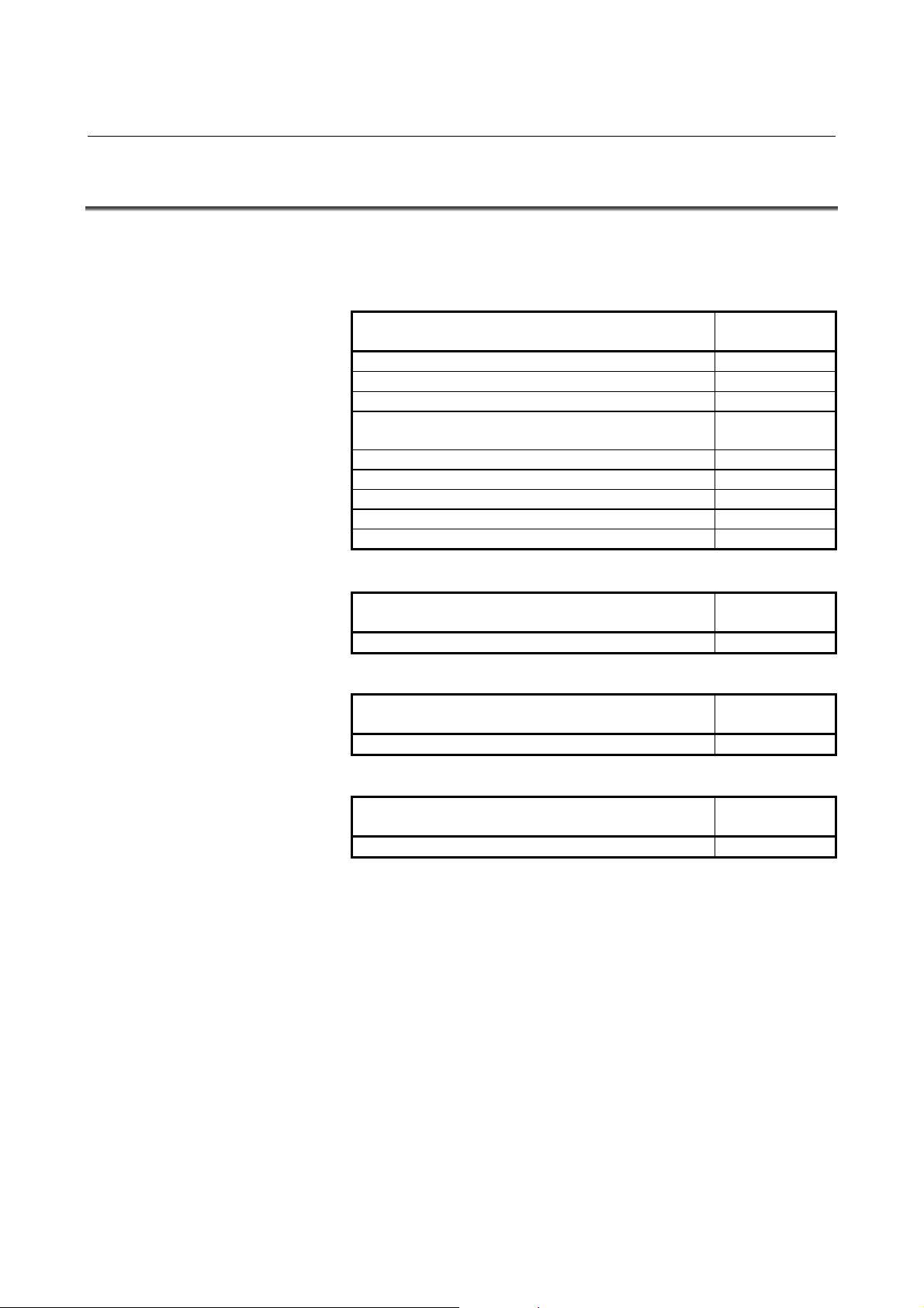
Model name Abbreviation
FANUC Series 0i-MODEL D Series 0i-D 0i-D
- 5 -
Page 18
1.GENERAL GENERAL B-64414EN/01
1.3 RELATED MANUALS
The table below lists manuals related to this Operator's Manual.
Refer to these manuals when you use this Operator's Manual.
Related manuals of FANUC Series 0i-D
Manual name
DESCRIPTIONS B-64302EN
CONNECTION MANUAL (HARDWARE) B-64303EN
CONNECTION MANUAL (FUNCTION) B-64303EN-1
USER’S MANUAL
(Common to Lathe System/Machining Center System)
USER’S MANUAL (For Lathe System) B-64304EN-1
USER’S MANUAL (For Machining Center System) B-64304EN-2
MAINTENANCE MANUAL B-64305EN
PARAMETER MANUAL B-64310EN
START-UP MANUAL B-64304EN-3
Related manuals of FANUC CIMPLICITY i CELL
Manual name
OPERATOR’S MANUAL B-75074EN
Related manuals of FANUC Machine Remote Diagnosis Package
Manual name
OPERATOR’S MANUAL B-63734EN
Related manuals of FANUC Program Transfer Tool
Manual name
OPERATOR’S MANUAL B-64344EN
Specification
number
B-64304EN
Specification
number
Specification
number
Specification
number
- 6 -
Page 19

II. SPECIFICATION
Page 20

Page 21

B-64414EN/01 SPECIFICATION 1.PREFACE
1 PREFACE
In this manual, a board that has an ATA Flash card or a Compact
Flash Card (collectively called a memory card hereinafter) mounted to
enable the use of the Data Server functions is referred to as a "FAST
Data Server" (or simply as a "Data Server"). On the other hand, a
board that does not have a memory card mounted is referred to as a
"FAST Ethernet".
Board name Usable function
- Data Server functions
- FOCAS2/Ethernet functions
FAST Data Server
(or simply referred to as "Data Server")
FAST Ethernet
NOTE
To use the Data Server functions, the Data Server
function option is required.
To use the FOCAS2/Ethernet functions, CNC
screen display functions, machine remote
diagnosis functions, unsolicited messaging
function, and FTP file transfer function, the
Ethernet function option is required.
- CNC screen display functions
- Machine remote diagnosis
functions
- Unsolicited messaging
function (FOCAS2/Ethernet)
- FOCAS2/Ethernet functions
- CNC screen display functions
- Machine remote diagnosis
functions
- Unsolicited messaging
function (FOCAS2/Ethernet)
- FTP file transfer function
- 9 -
Page 22

2.DATA SERVER FUNCTIONS SPECIFICATION B-64414EN/01
2 DATA SERVER FUNCTIONS
The Data Server functions use a memory card built into a board for
storing files and can transfer files and perform DNC operation using
FTP.
A Data Server can operate on both FTP client and FTP server.
When you use a Data Server to transfer files, the Data Server operates
as an FTP client and communicates with the FTP server on the host
computer.
When you use the host computer to transfer files, the Data Server
operates as an FTP server and communicates with the FTP client on
the host computer.
NOTE
1 When the host computer operates as an FTP
server, FTP server software must be run on the
host computer. When the host computer operates
as an FTP client, FTP client software must be run
on the host computer.
2 The Program Transfer Tool (drawing number:
A08B-9510-J513 [Version 3 or later]) is available
as a PC tool for transferring NC programs between
the CNC and personal computer. This tool allows
NC programs to be transferred between a personal
computer and CNC memory or Data Server
memory card through a simple operation on the
personal computer side. The transfer of NC
programs between a personal computer and CNC
memory requires the FOCAS2/Ethernet functions,
and that between a PC and Data Server memory
card requires the Data Server functions.
Chapter 2, "DATA SERVER FUNCTIONS", consists of the following
sections:
2.1 DATA SERVER FILE MANAGEMENT ..................................11
2.2 DATA SERVER MODES ..........................................................15
2.3 OPERATION FROM A DATA SERVER..................................17
2.4 NC PROGRAM FORMAT.........................................................19
2.5 LIST FILE FORMAT .................................................................21
2.6 ISO CODE INPUT/OUTPUT FUNCTION................................25
- 10 -
Page 23
B-64414EN/01 SPECIFICATION 2.DATA SERVER FUNCTIONS
FTP client
FTP client
Operation
FTP server
FTP server
CNC
CNC
memory
CNC
FTP sever
FAST Data Server
Ethernet
Hard disk
PUT
GET
FTP client
CNC
memory
FAST Data Server
Ethernet
GET
PUT
Operation
Hard disk
- 11 -
Page 24
2.DATA SERVER FUNCTIONS SPECIFICATION B-64414EN/01
2.1 DATA SERVER FILE MANAGEMENT
With the Data Server functions, you can format the built-in memory
card in the CNC file management mode to manage NC programs.
CNC file management
For NC programs managed in the CNC file management mode,
memory operation such as custom macro commands and M98-based
subprogram calling are available. Operate the NC programs using the
PROGRAM FOLDER screen in the same way as for NC programs in
the CNC memory.
As a CNC external input/output device, DNC operation and
M198-based subprogram calling are available. In this case, operate
NC programs using the DATA SERVER FILE LIST screen.
PROGRAM FOLDER screen
Edit operation
DATA SERVER FILE LIST
screen
CNC file management
(DNC operation is also available.)
File transfer operation
Memory operation
NOTE
1 The Data Server for the Series 0i-D allows editing
and memory operation of NC programs stored on
the memory card, so the method of managing files
on the memory card differs from the file
management method of conventional Data
Servers. Note that, therefore, the memory card of
the Series 0i-D is not compatible with the memory
cards of Data Server models for the Series 0i-C .
2 For operation and details of the DATA SERVER
FILE LIST screen, refer to Chapter 1,
"OPERATING THE DATA SERVER FUNCTIONS,"
in Part IV, "OPERATION."
- 12 -
Page 25

B-64414EN/01 SPECIFICATION 2.DATA SERVER FUNCTIONS
2.1.1 File Names of CNC File Management
A file name of CNC file management may be an arbitrary file name of
up to 32 characters.
• Up to 32 characters
• Alphabetic characters (in upper and lower cases), numeric
characters, and four symbols (+, -, _, and .)
NOTE
1 File names are case-sensitive.
2 Any file name or folder name cannot begin with a
period (.).
3 It is impossible to assign the same name to a file
and a folder.
File names and program numbers
When a file name assigned to a file consists of uppercase O and a
numeric value, the file name is treated as a program number.
Values ranging from 1 to 9999 can be used.
A value beyond this range cannot be used for a file name in the
program number format.
Example)
File names that can be used as program numbers
“O0123” Program number 123
“O0001” Program number 1
“O3000” Program number 3000
“O9999” Program number 9999
File names that cannot be used as program numbers
“ABC” (Does not have the format "O plus a numeric value")
“o123” (Does not begin with uppercase letter "O")
“O123.4” (Uses a character other than numeric characters)
NOTE
1 When files on a Data Server are managed by
program number, their program numbers always
consist of "O" plus a 4-digit number. So, even if
there are files managed with different file names
such as "O1" and "O01" on a personal computer,
their program numbers are regarded as the same
when these files are transferred to the Data Server.
2 When a text file assigned an arbitrary file name
other than a program number is input to the CNC
memory, it is necessary to specify the program
number set in the CNC memory.
- 13 -
Page 26

2.DATA SERVER FUNCTIONS SPECIFICATION B-64414EN/01
2.1.2 Files which can be Created on a Data Server
In the initial status, the maximum number of files which can be
created on a memory card on a Data Server is 2047 and the maximum
file size is 512 MB. Each folder is counted as one file.
The maximum number of files and the maximum file size can be
changed using NC parameter No. 930.
For details, see Section 2.3, "RELATED NC PARAMETERS," in Part
III, "SETTING."
2.1.3 Text Files and Binary Files
You can store the following two types of files on a memory card on a
Data Server: text files and binary files.
For a text file, memory operation and edit operation as well as DNC
operation can be performed by selecting it as a main program.
On the other hand, memory and edit operations cannot be performed
for a binary file.
If NC data other than an NC program is not handled as a binary file, it
may not be able to be input or output correctly. NC data punched and
stored on a memory card on a Data Server from the CNC is
automatically handled as a binary file. A file to be transferred from a
personal computer to a memory card on a Data Server must be
specified explicitly as a binary file.
More specifically, for GET operation on a Data Server operation
screen, you can use soft key [GET] or [BGET] to specify whether to
handle the file as a text file or a binary file.
When the Data Server is used as an FTP server, you can execute an
ASCII (text file) command or a BIN (binary file) command on your
personal computer (FTP client) to specify whether to handle the file as
a text file or a binary file.
NOTE
1 An NC program stored as a text file is converted to
an editable file format so that the file can be edited
on the CNC. For this reason, when a text file is
read from the host computer to the memory card
on the Data Server, then the file is transferred to
the host computer, binary compatibility can no
longer be maintained.
2 In the case of a text file, the file name and program
name are identical. If a file having a program name
different from the file name on the personal
computer side is transferred as a text file, the
program name is replaced by the file name.
Note, however, that only when the file is transferred
through an operation on the CNC side, precedence
can be given to the program name by setting bit 3
(DSF) of NC parameter No. 905.
- 14 -
Page 27
B-64414EN/01 SPECIFICATION 2.DATA SERVER FUNCTIONS
2.2 DATA SERVER MODES
Each Data Server mode determines the input or output destination
when a Data Server is operated as a CNC external input/output device.
You can select one of the following two modes.
NOTE
Data Server modes are valid only when the Data
Server is operated as an external storage device of
the CNC. In case of main program operation for
editing and a memory operation and an M98-based
subprogram call, programs on the memory card of
the Data Server are selected regardless of the
Data Server mode.
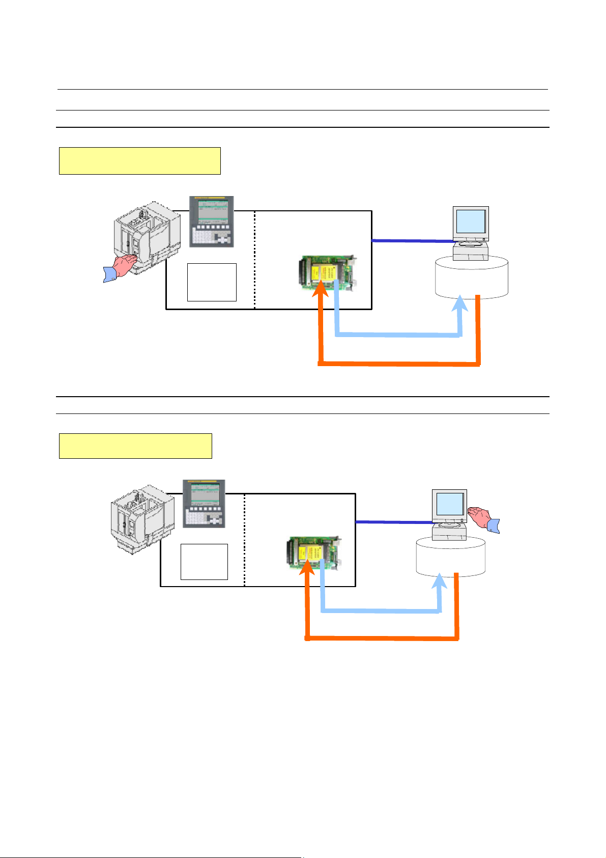
Storage mode
The memory card built into the Data Server is selected as the external
input/output device.
For example, when DNC operation or M198-based subprogram
calling is executed, the relevant NC program is called from the
memory card built into the Data Server.
When input operation is executed for the Data Server, the relevant NC
program is read from the memory card built into the Data Server.
Conversely, when NC program output operation is executed for the
Data Server, the output NC program is written on the memory card
built into the Data Server.
Input
FTP mode
Data Server
Memory card
Output
CNC memory
DNC operation
The host computer connected to the Data Server is selected as the
external input/output device.
For example, when DNC operation or M198-based subprogram
calling is executed, the relevant NC program is called from the host
computer.
When input operation is executed for the Data Server, the relevant NC
program is read from the host computer connected to the Data Server.
Conversely, when NC program output operation is executed for the
Data Server, the output NC program is directly written on the host
computer.
- 15 -
Page 28
2.DATA SERVER FUNCTIONS SPECIFICATION B-64414EN/01
Host computer
Data Server
Input
Output
CNC memory
DNC operation
CAUTION
1 In the FTP mode, an NC program is transferred
from the host computer to the CNC. For this
reason, if the line is disconnected during
communication for some reason such as noise on
the network, the disconnection directly affects the
CNC operation as compared with the storage
mode. Before DNC operation in the FTP mode,
surely take measures to prevent noise and make
sure that good communication conditions are
present.
2 When feed hold is performed during DNC
operation in the FTP mode, communication with
the host computer may be stopped. In this case,
the host computer may disconnect the
communication. Perform feed hold during a trial
run and completely confirm that the communication
with the host computer is not disconnected.
- 16 -
Page 29

B-64414EN/01 SPECIFICATION 2.DATA SERVER FUNCTIONS
2.3 OPERATION FROM A DATA SERVER
Memory operation
You can perform memory operation for an NC program on the
memory card built into a Data Server in the same way as for an NC
program in the CNC memory.
You can also supply an NC program simultaneously for a multipath
CNC system.
NOTE
1 When memory operation is performed, a selected
program on the Data Server must be a text file. It is
impossible to use a binary file for memory
operation.
2 Memory and edit operations for the Data Server
can be performed only for NC programs stored in
the memory card built in the Data Server. Memory
and edit operations cannot be performed directly
for files on the host computer.
3 When memory operation is performed using a
program in the Data Server memory card as the
main program, a subprogram in the same folder as
the main program can be called by the M98
subprogram call.
M198 subprogram operation
In the storage mode, you can perform M198 calling from the memory
card built into a Data Server. In the FTP mode, you can perform M198
calling form the host computer.
On the DATA SERVER FILE LIST screen, set an M198 folder in
advance. When M198 calling is specified, the set M198 folder is
searched for the target subprogram.
NOTE
M198 subprogram operation cannot be performed
simultaneously for two paths.
- 17 -
Page 30

2.DATA SERVER FUNCTIONS SPECIFICATION B-64414EN/01
DNC operation
In the storage mode, you can perform DNC operation from the
memory card built into a Data Server. In the FTP, you can perform
DNC operation from the host computer.
On the DATA SERVER FILE LIST screen, set the file name for DNC
operation in advance. When DNC operation starts, the set DNC
operation file is called.
NOTE
DNC operation cannot be performed for the
second path.
- 18 -
Page 31

B-64414EN/01 SPECIFICATION 2.DATA SERVER FUNCTIONS
2.4 NC PROGRAM FORMAT
NC programs prepared on the host computer must have the following
format:
% TITLE ;
O0001(COMMENT) ;
⋅
⋅
⋅
M30 ;
%
An NC program starts with a tape start (%). In the subsequent part
(leader section) until EOB (;, program start) is encountered, a
comment such as a title can be inserted as necessary.
At the beginning of the program part, be sure to specify a program
name, which must be either an O number (program number) or an
arbitrary file name of not more than 32 characters enclosed by "<" and
">". This O number or file name must be used for management on the
personal computer.
If the O number in the NC program or the program name in the
arbitrary file name does not match the file name on the personal
computer, the file name on the personal computer is used as the
program name by default when the file is transferred from the personal
computer to the Data Server.
The semicolon ";" used at the end of each block means EOB (end of
block) and actually functions as LF (LF: 0A in hexadecimal), CR-LF
(CR: 0D in hexadecimal), or LF-CR-CR.
The NC program must end with "M code ; tape end (%)".
For information about the NC program structure, refer to the user's
manual (B-64304EN).
WARNING
If an NC program prepared on the host computer
does not use the program format specified by the
CNC, executing the NC program can cause an
unpredictable operation. So, special care should be
taken when an NC program is prepared on the host
computer.
- 19 -
Page 32

2.DATA SERVER FUNCTIONS SPECIFICATION B-64414EN/01
NOTE
1 Put "%" (tape end) at the end of the file. Do not
allow the program to continue beyond the tape
end.
2 Do not use any characters other than the usable
characters, including in comment sections. If any
unusable characters - Japanese characters in
particular - are used, they may be interpreted as
unexpected control characters.
3 EIA codes cannot be used for a Data Server.
4 When two or more NC programs are managed with
a single file on the host computer, transferring that
file to the Data Server memory card as a text file
results in those programs being registered as a
single NC program; the transferred file is not
automatically divided into separate NC programs.
- 20 -
Page 33

B-64414EN/01 SPECIFICATION 2.DATA SERVER FUNCTIONS
2.5 LIST FILE FORMAT
In the LIST-GET, LIST-PUT, and LIST-DELETE functions described
later, one of the following list file formats must be used:
Format 1
% ;
O0001(COMMENT) ;
N111 ;
N222 ;
N333 ;
:
:
N999 ;
%
Format 2
% ;
O0001(COMMENT) ;
N111 (PC-File) ;
N222 (PC-File) ;
N333 (PC-File) ;
:
:
N999 (PC-File) ;
%
Format 3
% ;
O0001(COMMENT) ;
(Dtsvr-File) ;
(Dtsvr-File) ;
(Dtsvr-File) ;
:
:
(Dtsvr-File) ;
%
Format 4
% ;
O0001(COMMENT) ;
(Dtsvr-File, PC-File) ;
(Dtsvr-File, PC-File) ;
(Dtsvr-File, PC-File) ;
:
:
(Dtsvr-File, PC-File) ;
%
- 21 -
Page 34

2.DATA SERVER FUNCTIONS SPECIFICATION B-64414EN/01
Specifications common to all formats
<1> A list file begins with a tape start "%".
<2> In the next block, be sure to specify an O number. Assign this O
number as the file name.
A comment enclosed in parentheses "(" and ")" can be inserted
between the O number and EOB.
<3> In the subsequent blocks, specify files to be processed.
<4> The list file must end with "%".
Specifications of format 1
The following describes the specifications of list file format 1:
<1> This specification method applies when the file names of files to
be processed have the format "Oxxxx" (where "xxxx" denotes a
4-digit number). In this case, change "O" in file name "Oxxxx" to
"N" when specifying the file name. The 4-digit number can be
zero-suppressed. The example shows that files O0111, O0222,
O0333, and so on up to O0999 are processed sequentially.
<2> The LIST-GET service transfers "Oxxxx" files stored on the
built-in hard disk of the host computer to the built-in memory
card of the FAST Data Server without modifying file names
"Oxxxx". The LIST-PUT service transfers "Oxxxx" files stored
on the built-in memory card of the FAST Data Server to the
built-in hard disk of the host computer without modifying file
names "Oxxxx". The LIST-DELETE service deletes "Oxxxx"
files stored on the built-in memory card of the FAST Data
Server.
Specifications of format 2
The following describes the specifications of list file format 2:
<1> This specification method applies when files to be processed are
named "Oxxxx" (where "xxxx" denotes a 4-digit number) on the
built-in memory card of the FAST Data Server and are named
arbitrary file names on the built-in hard disk of the host computer.
In this case, change "O" in file name "Oxxxx" to "N" when
specifying the file name on the FAST Data Server. The 4-digit
number can be zero-suppressed. The example shows that files
O0111, O0222, O0333, and so on up to O0999 are processed
sequentially.
A file name on the built-in hard disk of the host computer can be
specified by enclosing it with parentheses "(" and ")" following
the corresponding "Nxxxx". The characters that can be used in
file names depend on the OS of the host computer.
<2> The LIST-GET service transfers files with arbitrary file names
"PC-File" stored on the built-in hard disk of the host computer to
the built-in memory card of the FAST Data Server as "Oxxxx"
files. The LIST-PUT service transfers "Oxxxx" files stored on
the built-in memory card of the FAST Data Server to the built-in
hard disk of the host computer as files with arbitrary file names
"PC-File". The LIST-DELETE service deletes "Oxxxx" files
stored on the built-in memory card of the FAST Data Server.
- 22 -
Page 35

B-64414EN/01 SPECIFICATION 2.DATA SERVER FUNCTIONS
Specifications of format 3
The following describes the specifications of list file format 3:
<1> This specification method applies when the file names of files to
be processed are arbitrary file names. In this case, file names on
the built-in memory card of the FAST Data Server and on the
built-in hard disk of the host computer are assumed to be the
same. Specify an arbitrary file name enclosed with parentheses
"(" and ")". Arbitrary file names are those that can be used on the
Data Server side.
<2> The LIST-GET service transfers files with arbitrary file names
"Dtsvr-File" stored on the built-in hard disk of the host computer
to the built-in memory card of the FAST Data Server with the
file names kept unchanged.
The LIST-PUT service transfers "Dtsvr-File" files stored on the
built-in memory card of the FAST Data Server to the built-in
hard disk of the host computer with the file names "Dtsvr-File"
kept unchanged. The LIST-DELETE service deletes "Dtsvr-File"
files stored on the built-in memory card of the FAST Data
Server.
Specifications of format 4
The following describes the specifications of list file format 4:
<1> This specification method applies when files to be processed
have arbitrary file names. In this case, file names on the built-in
memory card of the FAST Data Server and file names on the
built-in hard disk of the host computer are assumed to be
different. Specify a file name on the built-in memory card of the
FAST Data Server and a file name on the built-in hard disk of the
host computer in parentheses, separated by a comma ",".
<2> The LIST-GET service transfers files with arbitrary file names
"PC-File" stored on the built-in hard disk of the host computer to
the built-in memory card of the FAST Data Server as
"Dtsvr-File" files.
The LIST-PUT service transfers "Dtsvr-File" files stored on the
built-in memory card of the FAST Data Server to files with file
name "PC-File" on the built-in hard disk of the host computer.
The LIST-DELETE service deletes "Dtsvr-File" files stored on
the built-in memory card of the FAST Data Server.
Limitations on file names in a list file
The following limitations apply when file names are specified in a list
file:
<1> As arbitrary file names on the built-in memory card of the FAST
Data Server, only the following 66 types of ASCII characters can
be used and the maximum length is 32 characters:
Numeric characters 0 to 9
Lowercase letters a to z
Uppercase letters A to Z
Four symbols (+, -, _, .)
- 23 -
Page 36

2.DATA SERVER FUNCTIONS SPECIFICATION B-64414EN/01
<2> The characters that can be used in arbitrary file names on the
built-in hard disk of the host computer depend on the OS of the
host computer.
Arbitrary file names may consist of up to 255 characters.
However, the number of characters that can actually be used
depends on the OS of the host computer.
Storage locations of list files
The LIST-GET, LIST-PUT, and LIST-DELETE services are useful
functions for managing NC programs in groups.
The places where list files are prepared vary depending on the service
to be executed.
For the LIST-GET service, NC programs to be operated on are present
on the built-in hard disk of the host computer, so list files are placed
also on the built-in hard disk of the host computer.
For the LIST-PUT and LIST-DELETE services, NC programs to be
operated on are present on the built-in memory card of the FAST Data
Server, so list files are also prepared on the built-in memory card of
the FAST Data Server.
- 24 -
Page 37

B-64414EN/01 SPECIFICATION 2.DATA SERVER FUNCTIONS
2.6 ISO CODE INPUT/OUTPUT FUNCTION
This function is intended to accomplish NC data input and output
between the CNC and Data Server, as well as between a personal
computer and Data Server, using the ISO code. Unlike the traditional
ASCII code characters, each ISO code character has parity data
appended to it. The function checks this parity data, which improves
the reliability of data input and output operations.
While the most significant bit of an ASCII code character is in an OFF
state, the ISO code uses the most significant bit to store parity data so
that each character has an even number of ON bits.
NOTE
1 NC data may not be transferred properly between
a personal computer and Data Server, depending
on the FTP communication software used on the
personal computer.
2 If a parity error is found in the ISO code in the
comment section, it is not regarded as an error and
the character in question is converted to a space.
3 If the ASCII code is selected as the input/output
code, the parity check is not performed. Even if the
data to be transferred is ISO code data, it is
transferred as ASCII code data with the parity data
in the most significant bit removed.
4 To input data to or output data from the CNC
requires that a Data Server be selected as the
input/output device. For information about
input/output device and input/output code
selection, see SETTING, Section 2.3, "RELATED
NC PARAMETERS".
5 A tool (FANUC ISO Converter) is available that
allows you to create and check ISO code NC data
on a personal computer. For details of this tool,
refer to the appendix of the "User’s Manual
(Common to Lathe System/Machining Center
System) (B-64304EN)".
- 25 -
Page 38

2.DATA SERVER FUNCTIONS SPECIFICATION B-64414EN/01
Input from the Data Server to CNC
If the ISO code is selected as the input/output code, an ISO code
check is performed to verify the validity of data when the CNC
receives the data from the Data Server.
If any character with invalid parity data is found, the input/output
operation ends abnormally.
Target functions
<1> Program input
<2> M198 subprogram call
<3> DNC operation
NOTE
1 The CNC checks the ISO code in the received
data, regardless of whether the Data Server file is
a text file or binary file.
For information about text files and binary files, see
Subsection 2.1.3, "Text Files and Binary Files".
2 The CNC checks the ISO code in the received
data, regardless of the Data Server mode.
In the FTP mode, therefore, ISO code NC data
needs to be prepared on the personal computer
side.
For information about the Data Server mode, see
Section 2.2, "DATA SERVER MODES".
Output from the CNC to Data Server
If the ISO code is selected as the input/output code, an ISO code
check is performed to verify the validity of data when the data is
stored in the Data Server memory card.
If any character with invalid parity data is found, the input/output
operation ends abnormally.
Target function
<1> Program output
NOTE
1 When the Data Server is in the FTP mode, data is
output directly to the personal computer and the
Data Server does not perform the ISO code check.
In this case, perform the check on the personal
computer side.
2 When more than one NC program is output
simultaneously or NC parameters are output, the
data is output to the Data Server as a binary file.
In the case of a binary file, the Data Server does
not perform the ISO code check.
- 26 -
Page 39

B-64414EN/01 SPECIFICATION 2.DATA SERVER FUNCTIONS
File transfer from a personal computer to Data Server
If the ISO code is selected as the input/output code, an ISO code
check is performed to verify the validity of data when the data
received from the personal computer is stored in the Data Server
memory card.
If any character with invalid parity data is found, the input/output
operation ends abnormally.
Target functions
<1> GET (Data Server = FTP client)
<2> PUT (Data Server = FTP server)
NOTE
1 It is necessary to prepare ISO code NC data on the
personal computer side.
2 In the case of binary file transfer, the ISO code
check is not performed when the data is stored in
the Data Server memory card.
File transfer from the Data Server to personal computer
If the ISO code is selected as the input/output code, data is output as
ISO code data from the Data Server memory card.
Target functions
<1> PUT (Data Server = FTP client)
<2> GET (Data Server = FTP server)
NOTE
1 Perform the ISO code check on the personal
computer side, as needed.
2 In the case of binary file transfer, the Data Server
does not perform ISO code conversion.
- 27 -
Page 40

3.FOCAS2/Ethernet FUNCTIONS SPECIFICATION B-64414EN/01
3 FOCAS2/Ethernet FUNCTIONS
The FOCAS2/Ethernet functions can remotely control and monitor the
CNC by using a personal computer. For details, refer to the manual
delivered with the FOCAS2 library software.
NOTE
1 In the FOCAS2/Ethernet functions, the CNC
operates as a server and waits for a
communication start request from a personal
computer that operates as a client.
As communication with the personal computer
starts, two sockets are used for control and
monitoring from the personal computer and for file
transfer.
2 The Program Transfer Tool (drawing number:
A08B-9510-J513 [Version 3 or later]) is available
as a PC tool for transferring NC programs between
the CNC and personal computer. This tool allows
NC programs to be transferred between a personal
computer and CNC memory or Data Server
memory card through a simple operation on the
personal computer side. The transfer of NC
programs between a personal computer and CNC
memory requires the FOCAS2/Ethernet functions,
and that between a PC and Data Server memory
card requires the Data Server functions.
- 28 -
Page 41

B-64414EN/01 SPECIFICATION 4.DNS/DHCP FUNCTIONS
4 DNS/DHCP FUNCTIONS
If DNS/DHCP functions are used for communication setting of the
Data Server functions and FOCAS2/Ethernet functions, Ethernet
addresses (IP address and subnet mask) can be set at a time on the host
computer to facilitate Ethernet address control.
DNS
With the DNS function, a fully qualified domain name (e.g.,
www.fanuc.co.jp
address just consisting of numbers (e.g., 192.168.0.10) when a TCP/IP
communication destination is to be specified.
NOTE
To use the DNS function, a personal computer
having the DNS server function is additionally
required. See APPENDIX D, "DNS/DHCP
FUNCTION."
DHCP
) can be specified instead of a hard-to-remember IP
With the DHCP function, Ethernet addresses (IP address and subnet
mask) that need to be set on the CNC can be set on the host computer.
NOTE
To use the DHCP function, a personal computer
having the DHCP server function is additionally
required. See APPENDIX D, "DNS/DHCP
FUNCTION."
- 29 -
Page 42

5. MACHINE REMOTE
DIAGNOSIS FUNCTIONS
SPECIFICATION B-64414EN/01
5 MACHINE REMOTE DIAGNOSIS
FUNCTIONS
With the machine remote diagnosis functions, checking of the internal
CNC status, ladder program editing, and other operations can be
performed as necessary by using a personal computer through a LAN.
For details, refer to “Machine Remote Diagnosis Package
OPERATOR’S MANUAL (B-63734EN).”
- 30 -
Page 43

6.UNSOLICITED MESSAGING
B-64414EN/01 SPECIFICATION
FUNCTION
6 UNSOLICITED MESSAGING FUNCTION
This chapter describes the unsolicited messaging function.
- 31 -
Page 44

6. UNSOLICITED MESSAGING
A
A
A
A
FUNCTION
SPECIFICATION B-64414EN/01
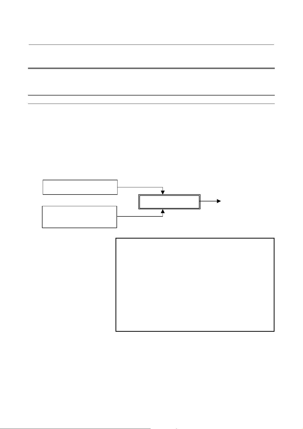
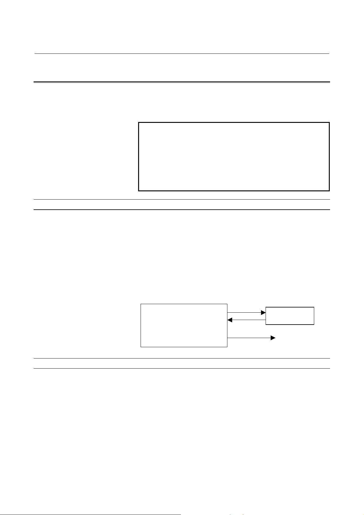
Overview of the unsolicited messaging function
An overview of the unsolicited messaging function is provided below.
With the unsolicited messaging function, the CNC transmits messages
(CNC/PMC data) in an unsolicited manner to application software on
the personal computer according to a command from an NC program
or ladder program. By using this function, the need for application
processing on the personal computer to periodically inquire about the
state of the CNC can be eliminated.
When the conventional function is used
Inquiry
Response
pplication software
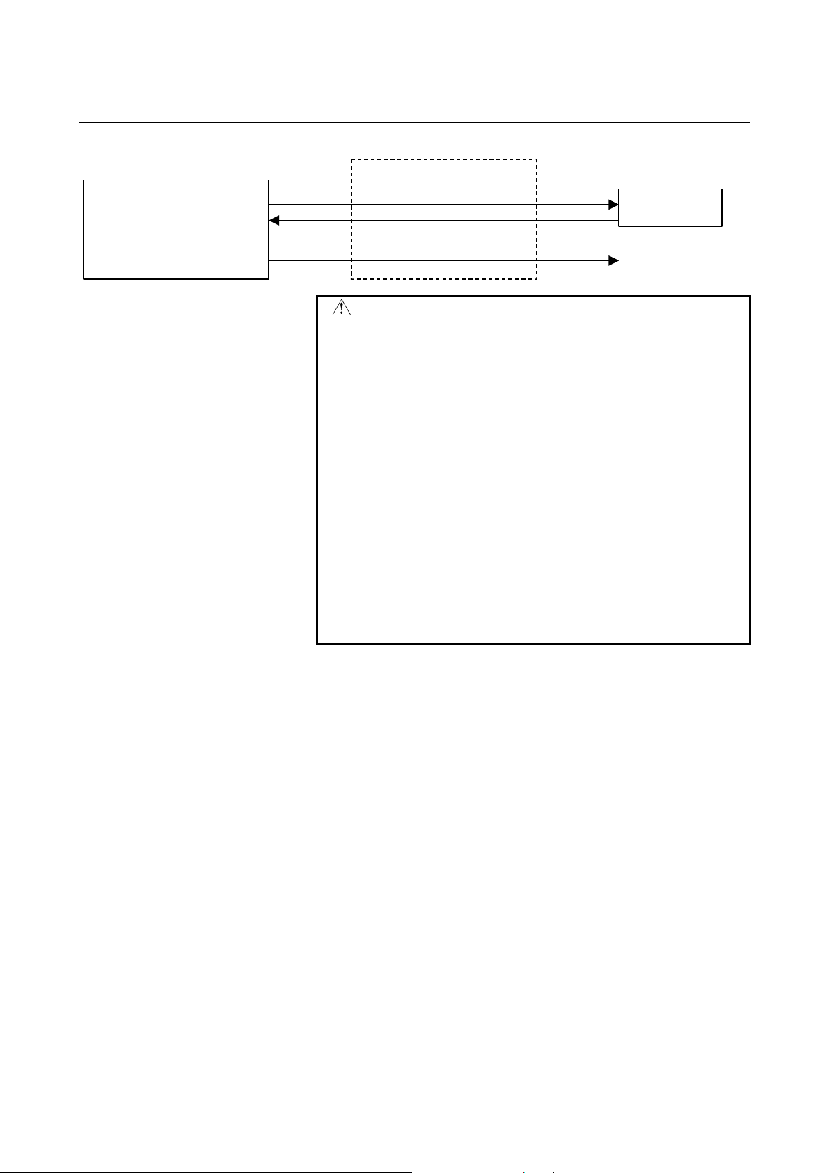
When the unsolicited messaging function is used
NC program or ladder
program checks for
CNC/PMC data
changes.
NC program or ladder
program
NOTE
The unsolicited messaging function is a part of the
pplication software
アプリケーションソフトウェア
Notification
FOCAS2/Ethernet function.
pplication checks for
CNC/PMC data changes.
pplication receives
notification from CNC.
- 32 -
Page 45

6.UNSOLICITED MESSAGING
B-64414EN/01 SPECIFICATION
FUNCTION
Unsolicited messaging function execution procedure
The execution procedure for the unsolicited messaging function is
described below.
1 Preparation on the personal compute
Create an application using the FOCAS2 function for the
unsolicited messaging function and install the unsolicited
message server on a personal computer. For the method of
creating an application using the FOCAS2 function for the
unsolicited messaging function and the method of installing the
unsolicited message server, refer to
MESSAGING FUNCTION", in "FANUC Open CNC
FOCAS1/FOCAS2 CNC/PMC Data Window Library Operator's
Manual".
2 Preparation on the CNC
Create an NC program or ladder program for controlling
unsolicited messaging.
For the method of creating an NC program or ladder program,
see Appendix F.2, "EXECUTING THE UNSOLICITED
MESSAGING FUNCTION."
3 Setting of the communication parameters for the
unsolicited messaging function
To use the unsolicited messaging function, the following
communication parameter settings are needed:
(1) Setting for using the FOCAS2/Ethernet function
(2) Setting of the parameters for the unsolicited messaging
function
For (2), a choice can be made from two modes of setting: CNC
mode for setting on the CNC screen and the PC mode for setting
on the personal computer.
For the setting method of (1) and (2), see Appendix F.1,
"SETTING OF THE UNSOLICITED MESSAGING
FUNCTION."
4 Starting the NC program or ladder program
Start the NC program or ladder program created in step 2,
"Preparation on the CNC". At this time, no unsolicited message
is transmitted to the personal computer until step 5, "Starting the
unsolicited messaging function", is executed.
5 Starting the unsolicited messaging function
Execute the FOCAS2 function cnc_unsolicstart on the personal
computer. This execution places the CNC in the state (named
"Ready") where a transmission request from the NC program or
ladder program is awaited. Each time a transmission request is
made from the NC program or ladder program, an unsolicited
message is automatically transmitted to the personal computer.
6 Ending the unsolicited messaging function
To end unsolicited message transmission, execute the FOCAS2
function cnc_unsolicstop on the personal computer. This
execution places the CNC in the state (named "Not Ready")
where no unsolicited message is transmitted even when a request
for transmission is made from the NC program or ladder
program.
Chapter 5, "UNSOLICITED
- 33 -
Page 46

7.FTP FILE TRANSFER FUNCTION SPECIFICATION B-64414EN/01
7 FTP FILE TRANSFER FUNCTION
The FTP file transfer function is operated from the CNC to transfer a
file. It works as an FTP client and communicates with the FTP server
on the host computer.
NOTE
1 The FTP server software needs to be running on
the host computer.
2 The FTP file transfer function cannot perform M198
subprogram calling or DNC operation.
- 34 -
Page 47

III. SETTING
Page 48

Page 49

1. SETTING THE COMMUNICATION
B-64414EN/01 SETTING
FUNCTION
1 SETTING THE COMMUNICATION
FUNCTION
This part describes the settings required to operate the following
FAST Ethernet/FAST Data Server functions:
• Data Server functions
• FOCAS2/Ethernet functions
• CNC screen display functions
NOTE
For details of the machine remote diagnosis
functions, unsolicited messaging function, and FTP
file transfer function, see the relevant appendixes.
Notes on using the Data Server functions
CAUTION
When setting the FAST Ethernet/FAST Data
Server for the first time, carefully set data such as
an IP address and conduct a sufficient
communication test, consulting with your network
administrator.
If data such as an IP address is not set correctly, a
communication failure can affect the entire
network. Take sufficient care.
- 37 -
Page 50

2. SETTING THE DATA
SERVER FUNCTIONS
SETTING B-64414EN/01
2 SETTING THE DATA SERVER
FUNCTIONS
This chapter describes the communication setting for the Data Server
functions.
Notes on using the functions for the first time
CAUTION
1 When using the FAST Data Server for the first time, be sure to
initialize the memory card, set parameters, then turn the power off
then back on. If an attempt is made to use the Data Server functions
without following these steps, normal operation is not guaranteed.
2 Before performing FTP communication using the FAST Data Server
for the first time, consult with your network administrator, carefully
set a network address and other items, and conduct communication
tests thoroughly. Any error in settings such as a network address
setting can lead to an adverse influence such as a communication
failure on the entire network.
In particular, IP address duplication causes an intermittent
communication failure in the Data Server, which can result in a
system error in the CNC. So, be very careful when making settings.
3 When the power to the CNC is turned off during access to the
memory card, files stored on the memory card may be destroyed.
So, be careful not to turn off the power to the CNC during access to
the memory card.
4 In preparation for damage to the memory card, always take backup
copies of the files stored on the memory card to the host computer.
NOTE
1 With the Data Server functions (FTP client), a single CNC can
connect only one FTP server.
2 With the Data Server functions (FTP server), a single CNC can
connect up to five FTP clients. However, some FTP client software
programs may each internally use two or more FTP clients. Note,
therefore, that the number of FTP clients is not always equal to the
number of applications.
3 The Data Server functions do not support passive mode (PASV
command).
- 38 -
Page 51

2. SETTING THE DAT
A
B-64414EN/01 SETTING
SERVER FUNCTIONS
2.1 OPERATING THE DATA SERVER SETTING SCREEN
This section describes the setting screen for operating the Data Server
functions.
Procedure
1 Press the function key .
2 Soft key [ETHBRD] appear. (When there is no soft keys, press
the continue key.)
3 Press soft key [ETHBRD] to display the Ethernet Setting screen.
4 Press soft keys [COMMON] and [DTSVR] and then enter
parameters for the items that appear.
- 39 -
Page 52

2. SETTING THE DATA
SERVER FUNCTIONS
SETTING B-64414EN/01
COMMON screen (BASIC)
Press soft key [COMMON] to display the COMMON screen
(BASIC).
Setting item
Display item
COMMON screen (BASIC)
Item Description
IP ADDRESS Specify the IP address of the FAST Data Server.
(Example of specification format: "192.168.0.100")
SUBNET MASK Specify a mask address for the IP addresses of the
network.
(Example of specification format: "255.255.255.0")
ROUTER IP
ADDRESS
Specify the IP address of the router.
Specify this item when the network contains a router.
(Example of specification format: "192.168.0.253")
Item Description
MAC ADDRESS FAST Data Server MAC address
NOTE
The second page (detail screen) of the COMMON
screen is to be set when the DNS/DHCP function is
used. For details, see Appendix D, "DNS/DHCP
FUNCTION."
- 40 -
Page 53

2. SETTING THE DAT
A
B-64414EN/01 SETTING
SERVER FUNCTIONS
Data Server screens (CONNECT 1, CONNECT 2, CONNECT 3)
Press soft key [DTSVR] to display the Data Server screen.
By using page keys
, the three host computers at
connection destinations 1, 2, and 3 can be set.
Data Server screen 1 (for connection destination 1)
Data Server screen 2 (for connection destination 1)
- 41 -
Page 54

2. SETTING THE DATA
SERVER FUNCTIONS
SETTING B-64414EN/01
Setting item
Item Description
HOST NAME
PORT NUMBER Specify the port number. Usually, set 21 because the
USER NAME Specify the name of the user to log on to the host
PASSWORD Specify the password for the above user name.
LOGIN FOLDER Specify a work folder to be used when the user logs in
Specify the IP address of the host computer.
(Example of specification format: "192.168.0.200")
FTP communication is used.
computer using FTP. (A user name of up to 31
characters can be specified.)
The password must always be specified.
to the host computer. (Up to 127 characters can be
specified.)
If no data is set, the home folder set on the host
computer is used as a login folder.
Operation
Select a connection destination.
1 Press soft key [(OPRT)] to display soft key [HOST]. Then, press
soft key [HOST] to display soft keys [CONECT1], [CONECT2],
and [CONECT3].
2 Press one of soft keys [CONECT1], [CONECT2], and
[CONECT3] according to the host computer to which you want
to make a connection. The screen title of connection destination
1, 2 or 3 is displayed in reverse video. The screen title displayed
in reverse video indicates the connection destination host
computer.
When connection destination 1 is selected
- 42 -
Page 55

2. SETTING THE DAT
A
B-64414EN/01 SETTING
SERVER FUNCTIONS
Data Server screens (FTP SERVER)
Press soft key [DTSVR] to display the Data Server screen.
By using page keys
, the FTP server setting screen is
displayed after the connection destination 1, 2, or 3 screen.
Data Server screen 1 (FTP SERVER)
Data Server screen 2 (FTP SERVER)
- 43 -
Page 56

2. SETTING THE DATA
SERVER FUNCTIONS
SETTING B-64414EN/01
Setting item
Item Description
USER NAME Specify a user name to be used when the host
computer logs in to the Data Server. (A user name of
up to 31 characters can be specified.)
PASSWORD Specify the password for the above user name.
The password must always be specified.
LOGIN FOLDER Specify a work folder to be used when the host
computer logs in to the Data Server. (Up to 127
characters can be specified.)
If no data is set, the home folder (home directory) is
used as a login folder.
- 44 -
Page 57

2. SETTING THE DAT
A
B-64414EN/01 SETTING
SERVER FUNCTIONS
Data Server MODE screen (SETTING)
Press soft key [DS MODE] to display the Data Server MODE screen
(SETTING). The current mode can be checked and changed.
Display item
Operation
Data Server screen (SETTING)
Item Description
CHANNELS Displays the number of channels currently being used.
MODE Displays the currently set Data Server mode.
STORAGE MODE
FTP MODE
The Data Server mode can be changed.
1 Press soft key [(OPRT)] to display soft keys [STORAGE] and
[FTP].
2 To change the mode to a desired mode, press the soft key of the
desired mode.
- 45 -
Page 58

2. SETTING THE DATA
SERVER FUNCTIONS
SETTING B-64414EN/01
Data Server MODE screen (MAINTENANCE)
Display item
Press soft key [DS MODE] and press page keys
display maintenance information for each channel.
Data Server MODE screen (MAINTENANCE)
Item Description
CHANNEL Interface number of the buffer used for transferring NC
programs between the CNC and Data Server.
For example, a channel is assigned to each path.
EMPTY
COUNTER
TOTAL SIZE Used for maintenance.
WRITE POINTER
READ POINTER
Used for maintenance.
This item indicates the number of cases where the
buffer becomes empty while NC programs are being
transferred from the Data Server to the CNC.
This item indicates the total number of bytes
transferred when an NC program is transferred from
the Data Server.
Used for maintenance.
This item indicates the buffer use status when NC
programs are transferred from the Data Server to the
CNC.
to
- 46 -
Page 59

2. SETTING THE DAT
A
B-64414EN/01 SETTING
SERVER FUNCTIONS
Data Server FORMAT screen
Press soft key [DS FMT] to display the format screen of the memory
card built into the Data Server.
Display item
Data Server FORMAT screen
Item Description
DEVICE NAME Indicates the storage media currently being used by
the Data Server.
"ATA" or "NONE" is indicated.
FORMAT TYPE Indicates the format type of the memory card.
"CNC FILE" or "---" is displayed.
When "---" is displayed, check whether the memory
card is mounted properly and is formatted correctly.
CHECK DISK
Indicates the check result.
When no check is made : “-----“
When the check result is normal : “OK”
When the check result is abnormal : “NG”
- 47 -
Page 60

2. SETTING THE DATA
SERVER FUNCTIONS
SETTING B-64414EN/01
Procedure (CHECK DISK)
1 Press soft key [(OPRT)] then soft key [CHKDSK].
2 Press soft key [EXEC] to check the format of the memory card
and display the check result.
CAUTION
If the check result is abnormal, determine the
cause of trouble from an error message displayed
on the ETHERNET LOG screen and back up the
files stored on the memory card immediately.
Then, try to reformat the memory card.
NOTE
1 An error occurs if other Data Server functions are
operated when a check disk is made.
2 Also when a program on the memory card of the
Data Server is selected as a main program, the
check disk operation cannot be performed.
Procedure (CNC FORMAT)
1 Press soft key [(OPRT)] then soft key [CNC FMT].
2 Press soft key [EXEC] to format the memory card built into the
FAST Data Server.
CAUTION
1 Do not turn off the power to the CNC when the
memory card is being formatted. Otherwise, the
memory card can be damaged.
2 When the memory card is formatted, all files held
on the memory card are erased.
NOTE
1 An error occurs if other Data Server functions are
operated when the memory card is formatted.
2 Also when a program on the memory card of the
Data Server is selected as a main program, the
memory card cannot be formatted.
- 48 -
Page 61

2. SETTING THE DAT
A
B-64414EN/01 SETTING
SERVER FUNCTIONS
2.2 INPUT OF SPECIAL CHARACTERS
By setting bits 4 and 5 (SI1 and SI2) of NC parameter No. 13115, it is
possible to input special characters and lowercase characters that are
not available on the MDI keys.
Setting this NC parameter displays soft key [CHA-EXT], and pressing
this soft key displays the following set of soft keys.
Each time you press soft key [ABC/abc], you switch from uppercase
input to lowercase input or vice versa. The uppercase/lowercase input
state can be checked in the key input field.
Uppercase input Lowercase input
- 49 -
Page 62

2. SETTING THE DATA
SERVER FUNCTIONS
SETTING B-64414EN/01
2.3 RELATED NC PARAMETERS
The NC parameters related to the Data Server functions are described
below.
#7 #6 #5 #4 #3 #2 #1 #0
0000 TVC
[Input type] Setting input
[Data type] Bit path
# 0 TVC When a file is transferred from the personal computer to the Data
Server, a TV check is:
0: Not performed.
1: Performed.
NOTE
This parameter is valid only for text files.
For text files, see Subsection 2.1.3, "Text Files and
Binary Files" in Part II, "SPECIFICATION."
0020 I/O CHANNEL : Input/output device selection
[Input type] Setting input
[Data type] Byte
[Valid data range] 5 : Selects the Data Server as the input/output device.
#7 #6 #5 #4 #3 #2 #1 #0
0100 NCR CRF CTV
[Input type] Setting input
[Data type] Bit
# 1 CTV When a file is transferred from the personal computer to the Data
Server, character counting for the TV check in program comment
parts is:
0: Performed.
1: Not performed.
# 2 CRF When a file is output from the Data Server to the personal computer,
EOB (end of block) is:
0: Set as specified by parameter NCR (bit 3 of parameter No. 100).
1: Set to "CR" "LF".
# 3 NCR When a file is output from the Data Server to the personal computer,
EOB (end of block) is:
0: Set to "LF" "CR" "CR".
1: Set to "LF".
- 50 -
Page 63

2. SETTING THE DAT
A
B-64414EN/01 SETTING
SERVER FUNCTIONS
NOTE
This parameter is valid only for text files.
For text files, see Subsection 2.1.3, "Text Files and
Binary Files" in Part II, "SPECIFICATION."
#7 #6 #5 #4 #3 #2 #1 #0
0904 LCH
[Input type] Setting input
[Data type] Bit
# 7 LCH In the LIST-GET service of the Data Server function, when a list file
specifies 1025 or more files:
0: A check for duplicated file names is performed.
1: A check for duplicated file names is not performed.
#7 #6 #5 #4 #3 #2 #1 #0
0905 DSF PCH
[Input type] Setting input
[Data type] Bit
# 1 PCH At the start of communication of the Data Server function, FTP file
transfer function, or machine remote diagnosis function, checking for
the presence of the server using PING is:
0: Performed.
1: Not performed.
NOTE
Usually, set 0.
If 1 is set not to check the presence of the server
by using PING, it may take several tens of seconds
to recognize an error when the server is not
present in the network.
For mainly security reasons, a personal computer
may be set so that it does not respond to the PING
command. To communicate with such a personal
computer, set 1.
# 3 DSF When an NC program is stored on the memory card of the Data
Server:
0: The file name takes priority.
1: The program name in the NC program takes priority.
NOTE
Only when the file in the personal computer is
registered to the memory card of the Data Server
by operating the CNC side, this parameter is
effective.
- 51 -
Page 64

2. SETTING THE DATA
SERVER FUNCTIONS
SETTING B-64414EN/01
#7 #6 #5 #4 #3 #2 #1 #0
0908 ISO
[Input type] Setting input
[Data type] Bit
# 0 ISO When the data server is selected as an I/O device, data is input or
output using:
0: ASCII codes
1: ISO codes
0921 Selects the host computer 1 OS.
0922 Selects the host computer 2 OS.
0923 Selects the host computer 3 OS.
[Input type] Parameter input
[Data type] Word
[Valid data range] 0 to 2
0: Windows95/98/Me/2000/XP/Vista.
1: UNIX, VMS.
2: Linux.
NOTE
Some FTP server software products do not depend
on the OS. So, even when the above parameters
are set, it is sometimes impossible to display a list
of files properly.
0929 File attribute specification during FTP server operation
[Input type] Parameter input
[Data type] Word
[Valid data range] 0 to 2
This parameter sets whether to give priority to the file attribute
specified in a TYPE command of FTP during operation as an FTP
server.
0: Priority is given to the file attribute specified in a TYPE
command from an FTP client.
1: Text files are always assumed.
2: Binary files are always assumed.
- 52 -
Page 65

2. SETTING THE DAT
A
B-64414EN/01 SETTING
Maximum number of files that can be registered to the memory card of the
0930
Data Server and maximum size per file that can be registered
[Input type] Parameter input
[Data type] Word
[Valid data range] 0, 10 to 15
No.930 Maximum number of files Maximum size per file
0 2047 512MB
10 511 2048MB
11 1023 1024MB
12 2047 512MB
13 4095 256MB
14 8191 128MB
15 16383 64MB
SERVER FUNCTIONS
NOTE
1 When the memory card is formatted after this
parameter is set, the maximum number of files and
maximum size per file are changed.
2 Each folder is counted as one file.
#7 #6 #5 #4 #3 #2 #1 #0
3107 SOR
[Input type] Setting input
[Data type] Bit path
# 4 SOR Display of the program directory
0: Programs are listed in the order of registration.
1: Programs are listed in the order of name.
#7 #6 #5 #4 #3 #2 #1 #0
13115 SI2 SI1
[Input type] Parameter input
[Data type] Bit
# 4 SI1 Soft key input of the characters shown below is:
0: Disabled.
1: Enabled.
< > ¥ % $ ! ~ : " '
# 5 SI2 Soft key input of the characters shown below and switching between
the uppercase and lowercase input modes by a soft key are:
0: Disabled.
1: Enabled.
( ) ? * & @ _
- 53 -
Page 66

2. SETTING THE DATA
SERVER FUNCTIONS
SETTING B-64414EN/01
2.4 EXAMPLE OF SETTING THE DATA SERVER FUNCTIONS
An example of setting for operating the Data Server functions is given
below. In this example of setting, one personal computer is connected
to two CNCs through a Data Server.
HUB
CNC 1
CNC 1 CNC 2
IP ADDRESS 192.168.0.100 192.168.0.101
SUBNET MASK 255.255.255.0 255.255.255.0
ROUTER IP ADDRESS None None
CONNECT 1
DATA SERVER MODE Storage Storage
NC Parameter NO. 20 5 5
PORT NUMBER 21 21
IP ADDRESS 192.168.0.200 192.168.0.200
USER NAME user user
PASSWORD user user
LOGIN FOLDER None None
PC 1
IP address
Sub-net mask
Default gateway
User name
Password
Home folder
192.168.0.200
255.255.255.0
None
user
user
default
CNC 2
"Microsoft TCP/IP property" of the personal computer
(Windows2000/WindowsXP/Vista) is used for setting.
"User acount” of the personal computer
(Windows2000/WindowsXP/Vista) is used for setting.
"Internet service manager" of the personal computer
(Windows2000/WindowsXP) is used for setting.
Windows Vista uses "FTP Publishing Service" for
setting.
10BASE-T or
100BASE-TX
PC 1
The common setting screen is
used for setting.
The Data Server setting screen
is used for setting.
The Data Server mode setting
screen is used for setting.
NC parameter setting
- 54 -
Page 67

3. SETTING THE FOCAS2/Ethernet
B-64414EN/01 SETTING
FUNCTIONS
3 SETTING THE FOCAS2/Ethernet
FUNCTIONS
This chapter describes the setting of parameters for the
FOCAS2/Ethernet functions and CNC screen display functions.
CAUTION
Before performing communication using the
FOCAS2/Ethernet functions for the first time,
consult with your network administrator, carefully
set a network address and other items, and
conduct communication tests thoroughly. Any error
in settings such as a network address setting can
lead to an adverse influence such as a
communication failure on the entire network.
In particular, IP address duplication causes an
intermittent communication failure in the Data
Server, which can result in a system error in the
CNC. So, be very careful when making settings.
Note on using the FOCAS2/Ethernet functions
NOTE
With the FOCAS2/Ethernet functions, up to 20
FOCAS2/Ethernet clients can be connected to one
CNC.
Note on using the CNC screen display functions
NOTE
With the CNC screen display functions, up to 1
CNC screen display function client can be
connected to one CNC.
- 55 -
Page 68

3. SETTING THE FOCAS2/Ethernet
FUNCTIONS
SETTING B-64414EN/01
3.1 OPERATING THE FOCAS2/Ethernet SETTING SCREEN
This section describes the setting screen for operating the
FOCAS2/Ethernet functions and CNC screen display functions.
Procedure
1 Press the function key .
2 Soft key [ETHBRD] appear. (When there is no soft keys, press
the continue key.)
3 Press soft key [ETHBRD] to display the Ethernet Setting screen.
4 Press soft keys [COMMON] and [FOCAS2] and then enter
parameters for the items that appear.
- 56 -
Page 69

3. SETTING THE FOCAS2/Ethernet
B-64414EN/01 SETTING
FUNCTIONS
COMMON screen (BASIC)
Press soft key [COMMON] to display the COMMON screen
(BASIC).
Setting item
Display item
COMMON screen (BASIC)
Item Description
IP ADDRESS Specify the IP address of the FAST Ethernet/ FAST
Data Server.
(Example of specification format: "192.168.0.100")
SUBNET MASK Specify a mask address for the IP addresses of the
network.
(Example of specification format: "255.255.255.0")
ROUTER IP
ADDRESS
Specify the IP address of the router.
Specify this item when the network contains a router.
(Example of specification format: "192.168.0.253")
Item Description
MAC ADDRESS FAST Ethernet/ FAST Data Server MAC address
NOTE
The second page (detail screen) of the COMMON
screen is to be set when the DNS/DHCP function is
used. For details, see Appendix D, “DNS/DHCP
FUNCTION.”
- 57 -
Page 70

3. SETTING THE FOCAS2/Ethernet
FUNCTIONS
SETTING B-64414EN/01
FOCAS2 screen
Press soft key [FOCAS2] to display the FOCAS2 screen.
Setting item
FOCAS2 screen
Item Description
PORT NUMBER
(TCP)
PORT NUMBER
(UDP)
TIME INTERVAL Set 0 when using this item for the FOCAS2/Ethernet
Specifies the port No. to be used by the
FOCAS2/Ethernet functions and CNC screen display
functions, within a range of 5001 to 65535.
Set 0 when using this item for the FOCAS2/Ethernet
functions and CNC screen display functions.
Set this port number to communicate with the FANUC
CIMPLICITY i CELL.
functions and CNC screen display functions.
Set this time interval to communicate with the FANUC
CIMPLICITY i CELL.
NOTE
1 For connection with the FANUC CIMPLICITY i CELL,
make the above setting according to "FANUC
CIMPLICITY i CELL OPERATOR'S MANUAL
(B-75074EN)."
2 The unit of TIME INTERVAL is 10 ms. The allowable
input range is 10 to 65535. Values less than 100 ms
cannot be set.
3 If a smaller value is set in TIME INTERVAL, the
communication load can increase to adversely affect
the performance of the network.
Example) If 100 is set, broadcast data is transmitted at
intervals of 1 second [1000 ms] (=100×10).
- 58 -
Page 71

3. SETTING THE FOCAS2/Ethernet
B-64414EN/01 SETTING
FUNCTIONS
3.2 RELATED NC PARAMETERS
0020 I/O CHANNEL : Input/output device selection
[Input type] Setting input
[Data type] Byte
[Valid data range] 6 : Selects the FOCAS2/Ethernet as the input/output device. This
parameter is required only for DNC operation, however.
#7 #6 #5 #4 #3 #2 #1 #0
0905 DNE
[Input type] Setting input
[Data type] Bit
# 0 DNE During DNC operation using the FOCAS2/Ethernet functions, the
termination of DNC operation is:
0: Waited.
1: Not waited.
0924 FOCAS2/Ethernet waiting time setting
[Input type] Parameter input
[Data type] Word
[Unit of data] millisecond
[Valid data range] 0 to 32767
When the FOCAS2/Ethernet and Data Server functions are used
simultaneously, this parameter sets the FOCAS2/Ethernet function
waiting time in milliseconds.
When a value of 0 is set, the functions operate with assuming that 1
millisecond is specified.
- 59 -
Page 72

3. SETTING THE FOCAS2/Ethernet
FUNCTIONS
SETTING B-64414EN/01
3.3 EXAMPLE OF SETTING THE FOCAS2/Ethernet
FUNCTIONS
An example of setting for operating the FOCAS2/Ethernet functions
is given below. In this example of setting, one personal computer is
connected to two CNCs through a FOCAS2/Ethernet.
CNC 1
CNC 1 CNC 2
IP ADDRESS 192.168.0.100 192.168.0.101
SUBNET MASK 255.255.255.0 255.255.255.0
ROUTER IP ADDRESS None None
PORT NUMBER (TCP) 8193 8193
PORT NUMBER (UDP) 0 0
TIME INTERVAL 0 0
PC 1
IP address 192.168.0.200
Sub-net mask 255.255.255.0
Default gateway None
CNC 1
CNC 2
NC IP address 192.168.0.100
NC TCP port number 8193
NC IP address 192.168.0.101
NC TCP port number 8193
HUB
10BASE-T or
100BASE-TX
PC 1
The common setting screen is used for
setting.
The FOCAS2 setting screen is used for
setting.
"Microsoft TCP/IP property" of the personal
computer (Windows 2000/XP/Vista) is used
for setting.
Specify these items with the arguments of
the data window library function
"cnc_allclibhnd13."
- 60 -
Page 73

4. ERROR MESSAGES DISPLAYED
B-64414EN/01 SETTING
DURING PARAMETER SETTING
4 ERROR MESSAGES DISPLAYED
DURING PARAMETER SETTING
This chapter explains the error messages that are issued when FAST
Ethernet/FAST Data Server parameters are set.
Messages Meaning and action to be taken
Communication Software
is not found
Ethernet board is not
found
Software Version Error The communication software version is illegal.
DATA IS OUT OF RANGE A numeric parameter value is beyond the range.
Wrong Character(s) An illegal character is used in a character parameter.
Format Error Input data such as an IP address has an illegal input format.
too many figures A value input in a numeric parameter consists of too many digits.
Data was rejected A parameter error is found.
Reading from SRAM failed
Writing into SRAM failed
DHCP is available When the DHCP client function is enabled, the parameters cannot set from the
Error(xxxx) Other errors.
Check whether the communication software is installed.
Check whether the Ethernet board is installed.
Check the software version.
Confirm the setting conditions described in the relevant manual.
SRAM may have been destroyed.
Check whether the necessary options and other items are properly set.
setting screen. To set the parameters, disable the DHCP client function.
Check the parameter settings and contact FANUC.
- 61 -
Page 74

5. BACKING UP OR RESTORING
COMMUNICATION PARAMETERS
SETTING B-64414EN/01
5 BACKING UP OR RESTORING
COMMUNICATION PARAMETERS
This chapter describes how to back up the FAST Ethernet/FAST Data
Server communication parameters to a memory card, as well as how to
restore the parameters from the memory card.
1. Press the function key
2. Press soft key [ETHBRD] to display soft key [COMMON].
3. After pressing soft keys [COMMON] - [(OPRT)], press soft key
[+]. The soft keys for backing up and restoring the
communication parameters - [BACKUP], [RESTORE],
[ALLBACK], and [ALL RES] - are displayed as shown below.
4. Press one of the soft keys - [BACKUP], [RESTORE],
[ALLBACK], and [ALL RES]. The soft keys [EXECUTE] and
[CANCEL] are displayed.
5. Input the name of the file to be backed up or restored to the
key-in buffer, and press soft key [EXECUTE]. The target
operation is performed.
While the operation is in progress, "EXECUTING" blinks.
.
- 62 -
Page 75

5. BACKING UP OR RESTORING
B-64414EN/01 SETTING
COMMUNICATION PARAMETERS
BACKUP
This saves the FAST Ethernet/FAST Data Server communication
parameters, stored in the SRAM of the CNC, to a memory card.
If a file name is specified in the key-in buffer, the parameters are
saved to the memory card using the specified file name. If no file
name is specified, "ETHERBRD.MEM" is used.
RESTORE
This reads the FAST Ethernet/FAST Data Server communication
parameters stored in a memory card and saves them to the SRAM of
the CNC.
If a file name is specified in the key-in buffer, the file having the
specified name is read from the memory card. If no file name is
specified, "ETHERBRD.MEM" is used.
ALLBACK
This saves all the effective embedded Ethernet, FAST Ethernet/FAST
Data Server, and PROFIBUS-DP master/slave communication
parameters, stored in the SRAM of the CNC, to a memory card.
If a file name is specified in the key-in buffer, the parameters are
saved to the memory card using the specified file name. If no file
name is specified, "NETWORK.MEM" is used.
ALL RES
This reads all the effective embedded Ethernet, FAST Ethernet/FAST
Data Server, and PROFIBUS-DP master/slave communication
parameters, stored in a memory card, and saves them to the SRAM of
the CNC.
Note that, if the communication function on the CNC side is disabled
for an effective communication parameter, that parameter is not saved
to the SRAM.
If a file name is specified in the key-in buffer, the file having the
specified name is read from the memory card. If no file name is
specified, "NETWORK.MEM" is used.
NOTE
1 The communication parameters can be backed up
or restored only in the MDI mode or during an
emergency stop,
2 Restoring the communication parameters causes
an alarm that requests that the power be turned off.
3 For the communication parameter backup or
restoration operation, a memory card is used,
regardless of the external input/output device
number (NC parameter No. 20).
- 63 -
Page 76

Page 77

IV. OPERATION
Page 78

Page 79

1.OPERATING THE DAT
A
B-64414EN/01 OPERATION
SERVER FUNCTIONS
1 OPERATING THE DATA SERVER
FUNCTIONS
This chapter describes how to operate the Data Server functions.
On the PROGRAM DIRECTORY screen, files on the CNC memory,
memory card, host computer connected via the embedded Ethernet,
memory card built into the FAST Data Server, or host computer
connected via the FAST Data Server can be handled by selecting a
device.
Series 0i-MODEL D
PROGRAM FOLDER screen
CNC memory
Memory card
Via embedded
Ethernet
File list
FAST Data Server
Memory card
Via FAST Data Server
File list
In this manual, the method of handling files on the memory card built
into the FAST Data Server and on the host computer connected via the
FAST Data Server is described.
- 67 -
Page 80

1. OPERATING THE DATA
SERVER FUNCTIONS
OPERATION B-64414EN/01
1.1 DEVICE CHANGE ON THE PROGRAM DIRECTORY
SCREEN
Procedure
1 Press the function key
2 Press soft key [DIR +] to display the PROGRAM DIRECTORY
screen. (When there is no soft keys, press the continue key.)
.
PROGRAM DIRECTORY screen
3 Press soft key [(OPRT)] then soft key [DEVICE] to display the
soft keys for selectable devices.
4 Press soft key [DTSVR] to display the DATA SERVER FILE
LIST screen, which lists the files stored in the built-in memory
card of the FAST Data Server.
5 Press soft key [DS HOST] to display the DATA SERVER HOST
FILE LIST screen, which lists the files stored in the host
computer connected with the Data Server.
- 68 -
Page 81

1.OPERATING THE DAT
A
B-64414EN/01 OPERATION
SERVER FUNCTIONS
1.2 OPERATING THE DATA SERVER FILE LIST SCREEN
The DATA SERVER FILE LIST screen lets you operate the files
stored in the built-in memory card of the Data Server.
DATA SERVER FILE LIST screen (8.4-inch LCD)
- 69 -
Page 82

1. OPERATING THE DATA
SERVER FUNCTIONS
OPERATION B-64414EN/01
DATA SERVER FILE LIST screen (10.4-inch LCD)
If the file list is longer than one page, you can scroll the screen by
using page keys
.
- 70 -
Page 83

1.OPERATING THE DAT
A
B-64414EN/01 OPERATION
SERVER FUNCTIONS
Display item
M198 FLD (M198 OPE FOLDER)
Displays a folder (directory) for M198-based subprogram calling. This
is effective when the Data Server is in the storage mode.
DNC FILE (DNC OPE FILE)
Displays a file name used when DNC operation is performed. This is
effective when the Data Server is in the storage mode.
CON HOST (CONNECT HOST)
Displays the work folder and the number of the host currently
connected.
USED / FREE (USED SIZE / FREE SIZE)
Displays the size used of the memory card built into the FAST Data
Server and the size that is free.
USED FL / FREE FL (USED FILES / FREE FILES)
Displays the total number of folders (files) in use of the Data Server
and the number of remaining free folders (files).
DEVICE
Displays the current device. If the memory card built into the FAST
Data Server is selected, "DATA_SV" is indicated.
CURRENT FOLDER
Displays the current work folder in the built-in memory card of the
FAST Data Server.
File list
Displays information about the files and folders in the current work
folder.
NOTE
Character strings within parentheses are those
that are displayed when the display unit of 10.4" is
used.
- 71 -
Page 84

1. OPERATING THE DATA
SERVER FUNCTIONS
OPERATION B-64414EN/01
Operation list
DIR +
Switches the file list information to overall display or detail display.
SEARCH
Searches for a file in the current work folder.
MAIN P (MAIN PROGRM)
Selects a file as a main program.
DEVICE (DEVICE CHANGE)
Enables a device for display on the PROGRAM DIRECTORY screen.
When selecting the memory card built into the FAST Data Server,
press soft key [DTSVR].
F INPUT
Inputs a program in the Data Server memory card to the CNC memory.
This can be performed only when the Data Server is in the storage
mode, the EDIT mode is on, and "5" is set in NC parameter No. 20.
FOUTPUT (F OUTPUT)
Outputs a program in the CNC memory to the Data Server memory
card.
This can be performed only when the Data Server is in the storage
mode, the EDIT mode is on, and "5" is set in NC parameter No. 20.
DNC SET
Specifies the file for which to perform DNC operation when the Data
Server is in the storage mode.
M198SET (M198 SET)
Specifies the folder for which to perform M198 subprogram calling
when the Data Server is in the storage mode.
DELETE
Deletes a file or folder.
RENAME
Renames a file or folder.
F CREAT (CREATE FOLDER)
Creates a sub-folder under the current work folder.
PUT
Transfers a file from the Data Server to the host computer.
MPUT
Transfers multiple files from the Data Server to the host computer.
- 72 -
Page 85

1.OPERATING THE DAT
A
B-64414EN/01 OPERATION
SERVER FUNCTIONS
LST-PUT (LIST-PUT)
Transfers multiple files from the Data Server to the host computer
according to a list file.
LST-DEL (LIST-DELETE)
Deletes multiple files from the Data Server according to a list file.
SELECT (SELECT START)
Selects multiple files.
COPY
Copies a file within the Data Server.
MOVE
Moves a file to another folder in the Data Server.
REFRESH
Updates the display information of the PROGRAM DIRECTORY
screen.
NOTE
1 The operations of soft keys [F CREAT], [DELETE],
[RENAME], [COPY], and [LST-DEL] are the target
operations of the memory protection key.
This means that when the memory protection key
is enabled, these operations result in a "WRITE
PROTECT" error and cannot be performed.
For information about the memory protection key,
refer to the CONNECTION MANUAL (FUNCTION)
(B-64303EN-1) of the CNC.
2 Character strings within parentheses are those that
are displayed when the display unit of 10.4" is
used.
- 73 -
Page 86

1. OPERATING THE DATA
SERVER FUNCTIONS
OPERATION B-64414EN/01
Status display
Performing any of the operations listed below displays the status at the
lower right part of the screen during the operation.
Operation Status
F INPUT INPUT
F OUTPUT OUTPUT
COPY
MOVE
SEARCH SEARCH
PUT
MPUT
LST-PUT(LIST-PUT)
EDIT
PUT
- 74 -
Page 87

1.OPERATING THE DAT
A
B-64414EN/01 OPERATION
SERVER FUNCTIONS
1.2.1 Displaying and Operating the File List
DETAIL OFF, DETAIL ON
The content of the displayed file list can be changed.
Each time you press soft key [DIR +], the list changes from DETAIL
OFF to DETAIL ON or vice versa.
In the DETAIL OFF mode, file names and creation dates are
displayed while, in the DETAIL ON mode, other file information such
as comments and file attributes are also displayed.
NOTE
1 For a file selected as a main program and a file
being used for memory operation, no comment is
displayed in detail display mode.
2 In the DETAIL ON mode, the comment immediately
after the file name is displayed. If no comment is
found, the data is displayed beginning from the top
of the file.
3 The file attribute of a binary file is displayed as
"R/B" to the right of the comment.
REFRESH
MOVE FOLDER
The content of the displayed file list can be refreshed.
Pressing soft key [REFRESH] refreshes the content of the displayed
file list.
A work folder can be moved.
1 By using cursor keys
2 Press the MDI key
.
, select a folder to be moved.
- 75 -
Page 88

1. OPERATING THE DATA
SERVER FUNCTIONS
OPERATION B-64414EN/01
CREATE FOLDER
A new folder can be created.
1 Move to the folder to create a new folder.
2 Key in a folder name.
3 Press soft key [F CREAT] ([CREATE FOLDER]).
NOTE
1 Up to six levels of folders can be created.
2 No duplicate folder name is allowed within the
same folder.
3 Each time a folder is created, the number of
programs that can be registered decreases by one.
4 No folder may be able to be created, depending on
the status such as operation state or protection
state.
DELETE FILE/FOLDER
A file or folder can be deleted.
1 By using cursor keys
deleted.
2 Press soft key [DELETE].
- Press soft key [EXEC] for execution.
- Press soft key [CANCEL] for cancellation.
, select a file or folder to be
NOTE
1 The initial folder cannot be deleted.
2 A folder can be deleted only when the folder is
empty.
(An empty folder means a folder that does not
contain any folder and file.)
3 If a folder contains a folder or file that has the
edit/display prohibition attribute set, the folder
appears to be empty but is not actually empty. So,
the folder cannot be deleted.
4 Files or folders may not be able to be deleted,
depending on the status such as operation state or
protection state.
- 76 -
Page 89

1.OPERATING THE DAT
A
B-64414EN/01 OPERATION
SERVER FUNCTIONS
DELETE (multiple files)
Multiple files can be deleted at a time.
1 Press soft key [SELECT] ([SELECT START]).
DELETE (specified range)
2 By using cursor keys
3 Press soft key [SELECT].
A selected file is displayed in reverse video.
Repeat steps 2 and 3 for files to be deleted.
4 Press soft key [DELETE].
• Press soft key [EXEC] for execution.
• Press soft key [CANCEL] for cancellation.
, select a file to be deleted.
NOTE
1 If a folder contains a file that has the edit/display
prohibition attribute set, the folder appears to be
empty but is not actually empty. So, the folder
cannot be deleted.
2 Up to 10 files can be selected at a time.
3 It is only files that can be specified in plural.
Specifying more than one folder at a time is not
allowed.
4 Files may not be able to be deleted, depending on
the status such as operation state or protection
state.
A specified range of files that have program numbers can be deleted.
1 Enter "Oxxxx,Oyyyy".
In xxxx, enter the smallest of the program numbers to be deleted.
In yyyy, enter the largest of the program numbers to be deleted.
3 Press soft key [DELETE].
• Press soft key [EXEC] for execution.
• Press soft key [CANCEL] for cancellation.
NOTE
1 A deletion range can be specified only for files
having program numbers. Files having arbitrary file
names cannot be deleted with this method.
2 Files may not be able to be deleted, depending on
the status such as operation state or protection
state.
- 77 -
Page 90

1. OPERATING THE DATA
SERVER FUNCTIONS
OPERATION B-64414EN/01
RENAME
A file or folder can be renamed.
COPY (within a folder)
1 By using cursor keys
renamed.
2 Key a new file name or folder name.
3 Press soft key [RENAME].
, select a file or folder to be
NOTE
1 The initial folder cannot be renamed.
2 No duplicate folder name or file name is allowed
within the same folder.
3 Files and folders may not be able to be renamed,
depending on the status such as operation state or
protection state.
In the Data Server, a file can be copied within the same folder.
1 Set the CNC to the EDIT mode.
2 By using cursor keys
3 Key the name of a copy destination file.
4 Press soft key [COPY].
, select a copy source file.
NOTE
1 Copy operation is impossible if the same file is
specified as a copy source file and copy destination
file.
2 Files may not be able to be copied, depending on
the status such as operation state or protection
state.
- 78 -
Page 91

1.OPERATING THE DAT
A
B-64414EN/01 OPERATION
SERVER FUNCTIONS
COPY (multiple files)
More than one file can be copied to another folder in the Data Server.
1 Set the CNC to the EDIT mode.
2 Press soft key [SELECT] ([SELECT START]).
3 By using cursor keys
4 Press soft key [SELECT].
A selected file is displayed in reverse video.
Repeat steps 3 and 4 for files to be copied.
5 Press soft key [SEL END] ([SELECT END]).
6 Move to a copy destination folder.
7 Press soft key [COPY].
, select a copy source file.
NOTE
1 Copy operation is impossible if the same folder is
specified as a copy source folder and copy
destination folder.
2 Up to 10 files can be selected at a time.
3 Files retain their original file names when they are
copied to the copy destination folder. If any
identical file name exists in the copy destination
folder, an error occurs.
4 Files may not be able to be copied, depending on
the status such as operation state or protection
state.
- 79 -
Page 92

1. OPERATING THE DATA
SERVER FUNCTIONS
OPERATION B-64414EN/01
MOVE
A file can be moved to another folder in the Data Server.
1 Set the CNC to the EDIT mode.
2 Press soft key [SELECT] ([SELECT START]).
3 By using cursor keys
4 Press soft key [SELECT].
A selected file is displayed in reverse video.
5 Press soft key [SEL END] ([SELECT END]).
6 Move to a move destination folder.
7 To change the file name, key in a new file name.
When no file name is keyed in, the original file name is used.
8 Press soft key [MOVE].
, select a copy source file.
NOTE
1 Move operation is impossible if the same folder is
specified as a move source folder and move
destination folder.
2 Files may not be able to be copied, depending on
the status such as operation state or protection
state.
- 80 -
Page 93

1.OPERATING THE DAT
A
B-64414EN/01 OPERATION
SERVER FUNCTIONS
MOVE (multiple files)
More than one file can be moved to another folder in the Data Server.
1 Set the CNC to the EDIT mode.
2 Press soft key [SELECT] ([SELECT START]).
SEARCH
3 By using cursor keys
4 Press soft key [SELECT].
A selected file is displayed in reverse video.
Repeat steps 3 and 4 for files to be copied.
5 Press soft key [SEL END] ([SELECT END]).
6 Move to a move destination folder.
7 Press soft key [MOVE].
, select a copy source file.
NOTE
1 Move operation is impossible if the same folder is
specified as a move source folder and move
destination folder.
2 Up to 10 files can be selected at a time.
3 Files retain their original file names when they are
moved to the move destination folder. If any
identical file name exists in the move destination
folder, an error occurs.
4 Files may not be able to be copied, depending on
the status such as operation state or protection
state.
The current work folder can be searched for a file or folder. The file or
folder found is displayed at the top of the file list.
1 Key in the name of the file or folder to find.
2 Press soft key [SEARCH].
- 81 -
Page 94

1. OPERATING THE DATA
SERVER FUNCTIONS
OPERATION B-64414EN/01
LIST-DELETE
By using a list file, multiple files in the Data Server can be deleted.
1 By using cursor keys
2 Press soft key [LST-DEL] ([LIST-DELETE]).
• Press soft key [EXEC] for execution.
• Press soft key [CANCEL] for cancellation.
When execution is selected, the files in the Data Server are deleted
according to the list file.
, select a list file.
NOTE
Files cannot sometimes be deleted depending on
the operation status and protection status.
- 82 -
Page 95

1.OPERATING THE DAT
A
B-64414EN/01 OPERATION
SERVER FUNCTIONS
1.2.2 File Transfer Operation
Files can be transferred from the Data Server to the host computer.
NOTE
If an error occurs, check the cause of the error
according to the Item, “ETHERNET LOG screen” in
Section 2.1, ”Ethernet LOG” in Part VI,
“MAINTENANCE.”
PUT
A file can be transferred from the Data Server to the host computer.
PUT (multiple files)
1 By using cursor keys
2 Press soft key [PUT].
3 When a file is to be transferred to the host computer under a
different file name, enter the desired transfer destination file
name before pressing soft key [PUT].
Multiple files can be transferred from the Data Server to the host
computer.
1 Press soft key [SELECT] ([SELECT START]).
2 By using cursor keys
3 Press soft key [SELECT].
A selected file is displayed in reverse video.
Repeat steps 2 and 3 for files to be copied.
4 Press soft key [SEL END] ([SELECT END]).
5 Press soft key [PUT].
, select a file to be transferred.
, select a file to be transferred.
NOTE
1 Files cannot be transferred with their names
changed.
2 Up to 10 files can be selected at a time.
- 83 -
Page 96

1. OPERATING THE DATA
SERVER FUNCTIONS
OPERATION B-64414EN/01
MPUT
Multiple files can be transferred from the Data Server to the host
computer.
1 Key in the names of the files to transfer. File names can be
specified using wildcards (*, ?).
"?" represents any single character, and "*" any combination of
characters.
2 Press soft key [MPUT].
NOTE
If "*" is specified, any characters specified after it
are ignored.
For example, "ABC*DEF" is considered to be
equivalent to "ABC*".
LIST-PUT
Multiple files can be transferred from the Data Server to the host
computer according to a list file.
1 By using cursor keys
2 Press soft key [LST-PUT] ([LIST-PUT]).
, select a list file.
- 84 -
Page 97

1.OPERATING THE DAT
A
B-64414EN/01 OPERATION
SERVER FUNCTIONS
1.2.3 Preparations for File Operation and Editing
MAIN PROGRM
A selected file can be registered as a main program.
1 Select the EDIT mode or MEM mode.
2 By using cursor keys
a main program.
3 Press soft key [MAIN P] ([MAIN PROGRM]).
A registered main program can be executed in memory operation or
edited.
, select a file to be registered as
NOTE
1 Only a text file can be selected as a main program.
2 When memory operation is performed using a
program in the Data Server memory card as the
main program, a subprogram in the same folder as
the main program can be called by the M98
subprogram call.
3 For a file selected as a main program and a file
being used for memory operation, no comment is
displayed in detail display mode.
4 For a file selected as a main program, other file
operations are disabled.
5 For memory operation and editing, refer to the
USER'S MANUAL of the CNC.
6 No file may be able to be selected, depending on
the status such as operation state or protection
state.
- 85 -
Page 98

1. OPERATING THE DATA
SERVER FUNCTIONS
OPERATION B-64414EN/01
M198 SET
A folder for M198-based subprogram calling can be specified.
1 Move to the folder containing a file to be called by M198-based
subprogram calling.
2 Press soft key [M198SET] ([M198 SET]).
3 The specified folder is displayed in "M198 FOLDER" ("M198
OPE FOLDER").
NOTE
1 This setting is valid when the operating mode of the
Data Server is the storage mode.
2 This setting is saved in nonvolatile memory. Even if
the power is turned off and then back on, the last
saved setting remains.
3 No file may be able to be selected, depending on
the status such as operation state or protection
state.
DNC SET
A file used for DNC operation can be selected.
1 Move to the folder containing a file to be used for DNC
operation.
2 By using cursor keys
DNC operation.
3 Press soft key [DNC SET].
4 The specified file is displayed in "DNC FILE" ("DNC OPE
FILE").
, select a file to be used for
NOTE
1 This setting is valid when the operating mode of the
Data Server is the storage mode.
2 This setting is deleted when the power is turned off.
3 No file may be able to be selected, depending on
the status such as operation state or protection
state.
- 86 -
Page 99

1.OPERATING THE DAT
A
B-64414EN/01 OPERATION
SERVER FUNCTIONS
1.3 OPERATING THE DATA SERVER HOST FILE LIST
SCREEN
Host computer files can be operated on the DATA SERVER HOST
FILE LIST screen.
DATA SERVER HOST FILE LIST screen (8.4-inch LCD)
- 87 -
Page 100

1. OPERATING THE DATA
SERVER FUNCTIONS
OPERATION B-64414EN/01
DATA SERVER HOST FILE LIST screen (10.4-inch LCD)
NOTE
A file name including characters other than ASCII
characters is not displayed correctly.
- 88 -
 Loading...