


ERPB2-8C, ERPB2-8RAC, ERPBV2-8C, ERPBV2-8RAC, LRPB2-8C, LRPB2-8RAC, ERPB2-8C*2C, ERPB2-8C*3C
ERPB2-8GRNC*A, ERPB2-8GRNRAC*A, LRPB2-8GRNC*A, LRPB2-8GRNRAC*A
INSTALLATION, CARE & USE MANUAL
SWIRLFLOT M Refrigerated fountains with FLEXI-GUARDT M
ERPB2-8C
INSTALLER
Review these instructions before beginning installation. Be sure that installation conforms to all plumbing, electrical and other applicable codes.
When installation is complete, ensure these instructions are left in the plastic bag provided inside the installed unit for future reference.
Service to be performed by authorized service personnel only.
NOTE: It is common practice to ground electrical hardware such as telephones, computers and other devices to available water lines. This can, however, cause electrical feedback in the plumbing circuit, which results in an “electrolysis” effect occurring in the fountain. This may result in water which has a metallic taste to it or has a noticeable increase in the metallic content of the water.
When inspecting plumbing circuit, remember the line may be grounded some distance from the installation, and may occur outside the building or area in which the unit is being installed.
This condition can be avoided (in most cases) by using recommended materials during installation. Any drain fittings provided by the installer should be made of plastic which will electronically isolate the fountain from the remainder of the building’s plumbing circuits.
Page 1 |
97924C (Rev. G - 2/12) |

ERPB2-8C, ERPB2-8RAC, ERPBV2-8C, ERPBV2-8RAC, LRPB2-8C, LRPB2-8RAC, ERPB2-8C*2C, ERPB2-8C*3C
ERPB2-8GRNC*A, ERPB2-8GRNRAC*A, LRPB2-8GRNC*A, LRPB2-8GRNRAC*A
Model LRPB2-8RAC
Model LRPB2-8C
Figure 1 - Rough-in Dimensions
- Water Outlet Connection - Water Inlet Connection |
INLET |
|
Tube Tube |
||
|
Tube |
|
|
Waste |
|
1/4” |
ELECTRICAL |
|
O.D. O.D. |
|
|
LEGEND |
3/8” 11/4”- |
|
|
D |
|
|
= = |
|
= |
= |
|
A B C |
||
97924C (Rev. G - 2/12) |
Page 2 |
ERPB2-8C, ERPB2-8RAC, ERPBV2-8C, ERPBV2-8RAC, LRPB2-8C, LRPB2-8RAC, ERPB2-8C*2C, ERPB2-8C*3C
ERPB2-8GRNC*A, ERPB2-8GRNRAC*A, LRPB2-8GRNC*A, LRPB2-8GRNRAC*A
REQUIRED TOOLS AND MATERIALS
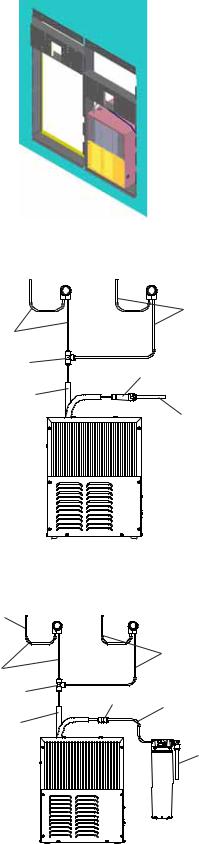
Figure 2 - Chiller Installation
TO BUBBLER 

26
26
27 |
28 |
|
CHILLER
OUTLET CHILLER INLET
Figure 3 - ERPB Tube Routing
TO BUBBLER
26
26 |
|
|
27 |
42 |
|
|
26 |
|
|
|
|
CHILLER |
|
|
OUTLET |
|
|
WATER
INLET
These tables show special tools and/or additional materials (not provided) which are necessary to complete installation of these units:
|
Special Tools |
|
|
|
|
Item |
Description |
Quantity |
|
NONE |
|
|
Additional Materials |
|
Item |
Description |
Quantity |
1 |
Unplated copper inlet pipe |
|
2 |
Service Stop |
|
1. Install chiller: Remove front panel of chiller. Remove and discard cardboard inner pack from between compressor and side panel. Slide chiller onto the shelf and position it to the left as per dimensions in Figure 1.
Note: Building construction must allow for adequate air flow on both sides, top and back of chiller. A minimum of 4” (102mm) on both sides and top is required. See chiller installation for additional instructions.
2. Make water supply connections. Install a shut-off valve and union connection to building water supply (valve and union not provided). Turn on water supply and flush the line thoroughly.
3. ERPB Models: Make connection between remote chiller and building supply line. Inlet port is marked on the chiller (1/4” O.D. copper tube). Bend the copper tube (provided) at an appropriate length from chiller to opening in frame.
Install the in-line strainer (provided with chiller) by pushing it until it reaches a positive stop, approximately 3/4” (19mm) on the marked chiller inlet port. Connect building supply
line to strainer. (See Figure 3)
Caution: DO NOT SOLDER tubes inserted into the strainer as damage to o-rings may result.
4. LRPB Models: Mount filter head assembly to side of chiller (See Figure 4). Make connections between filter and building supply line (3/8” O.D. tube not porvided). Inlet port is marked on the chiller (1/4” O. D. copper tube).
Install a 1/4” x 1/4” union (provided) on the marked chiller inlet port. Insert the 1/4” poly tubing (provided) into the fitting on filter and connect the union to the chiller.
(See Figure 4)
Caution: DO NOT SOLDER tubes inserted into the strainer as damage to o-rings may result.
Figure 4 - LRPB Tube Routing
Page 3
97924C (Rev. G - 2/12)
 Loading...