


Elkay EZSTL8WSX2A, EZSTLR8WSX1A, EZSTLDWSX1A, EZSTL8WSX3A, EZSDWSX1A User Manual
...EZS8WS*1A EZS8WS*2A EZS8WS*3A EZSDWS*1A
EZSTL8WS*1A EZSTLR8WS*1A EZSTL8WS*2A EZSTL8WS*3A EZSTLDWS*1A
INSTALLATION, CARE & USE MANUAL
EZS8WS EZH2OTMBOTTLE FILLING STATION & COOLER
IMPORTANT
THIS IS AN INDOOR APPLICATION ONLY.
ALL SERVICE TO BE PERFORMED BY AN
AUTHORIZED SERVICE PERSON.
TOOLS REQUIRED
BUT NOT PROVIDED:
SAFETY GLASSES
GLOVES
ELECTRIC DRILL
3/4” WRENCH OR CRECENT WRENCH 5/16” NUT DRIVER
UTILITY KNIFE
TAPE MEASURE
PENCIL
CENTER PUNCH
1/2” SOCKET & RATCHET WRENCH 5/32” ALLEN WRENCH
IMPORTANT! INSTALLER PLEASE NOTE.
THE GROUNDING OF ELECTRICAL EQUIPMENT SUCH AS TELEPHONE, COMPUTERS, ETC. TO WATER LINES IS A COMMON PROCEDURE. THIS GROUNDING MAY BE IN THE BUILDING OR MAY OCCUR AWAY FROM THE BUILDING. THIS GROUNDING CAN CAUSE ELECTRICAL FEEDBACK INTO A FOUNTAIN, CREATING AN ELECTROLYSIS WHICH CAUSES A METALLIC TASTE OR AN INCREASE IN THE METAL CONTENT OF THE WATER. THIS CONDITION IS AVOIDABLE BY USING THE PROPER MATERIALS AS INDICATED. ANY DRAIN FITTINGS PROVIDED BY THE INSTALLER SHOULD BE MADE OF PLASTIC TO ELECTRICALLY ISOLATE THE FOUNTAIN FROM THE BUILDING PLUMBING SYSTEM. WE SUGGEST THAT THE BOTTLE FILLING STATION AND WATER COOLER BE PROTECTED BYAGROUND FAULT CIRCUIT INTERRUPTER (GFCI).
INSTALLER
EZS8WS Bottle Fillers are among the easiest to install on the market today. To insure you install these models easily and correctly, PLEASE READ THESE SIMPLE INSTRUCTIONS BEFORE STARTING THE INSTALLATION. CHECK YOUR INSTALLATION FOR COMPLIANCE WITH PLUMBING, ELECTRICAL, AND OTHER APPLICABLE CODES. After installation, leave these instructions with the Fountain for future reference.
Page 1 |
98706C (Rev. D - 9/11) |

|
EZS8WS*1A |
EZS8WS*2A |
EZS8WS*3A |
EZSDWS*1A |
||||
|
EZSTL8WS*1A |
EZSTLR8WS*1A |
EZSTL8WS*2A |
EZSTL8WS*3A |
EZSTLDWS*1A |
|||
|
|
17 7/8 |
|
|
|
|
|
|
|
|
454mm |
|
|
|
|
3 9/16 |
|
|
7 |
|
|
7 |
|
|
||
|
|
|
|
|
90mm |
|||
|
178mm |
|
|
178mm |
|
|
|
|
7/16 |
O |
|
|
|
|
|
|
|
11mm |
|
|
|
|
|
|
|
|
MOUNTING HOLES |
|
|
|
|
|
|
|
|
(6) |
|
|
|
15 |
|
|
|
18 13/16 |
|
|
|
|
381mm |
|
|
|
478mm |
|
|
|
|
Single Rough-In |
|
|||
|
|
|
|
|
Fig. 1 |
|
|
|
|
17 7/8 |
|
|
|
|
|
|
|
|
454mm |
|
|
|
|
|
|
|
7 |
|
7 |
|
|
|
|
3 9/16 |
|
|
|
|
|
|
90mm |
|||
178mm |
|
178mm |
|
|
|
|
||
|
|
|
|
|
|
|||
7/16 |
O |
|
|
|
|
|
|
|
11mm |
|
|
|
|
|
|
|
|
MOUNTING HOLES |
|
|
|
|
|
|
|
|
(6) |
|
|
15 |
|
|
|
|
18 13/16 |
|
|
|
381mm |
|
|
|
|
478mm |
|
|
|
|
Two -Level Rough-In |
|
|||
|
|
|
|
|
Fig. 2 |
|
|
|
98706C (Rev. D - 9/11) |
|
|
Page 2 |
|
|
|
||
EZS8WS*1A EZS8WS*2A EZS8WS*3A EZSDWS*1A
EZSTL8WS*1A EZSTLR8WS*1A EZSTL8WS*2A EZSTL8WS*3A EZSTLDWS*1A
7/16” BOLT HOLES FOR |
|
MOUNTING |
|
FASTENING UNIT TO WALL |
|
||
TOP COVER |
SCREWS |
||
|
|||
UNIT CENTER LINE |
|
||
|
|
|
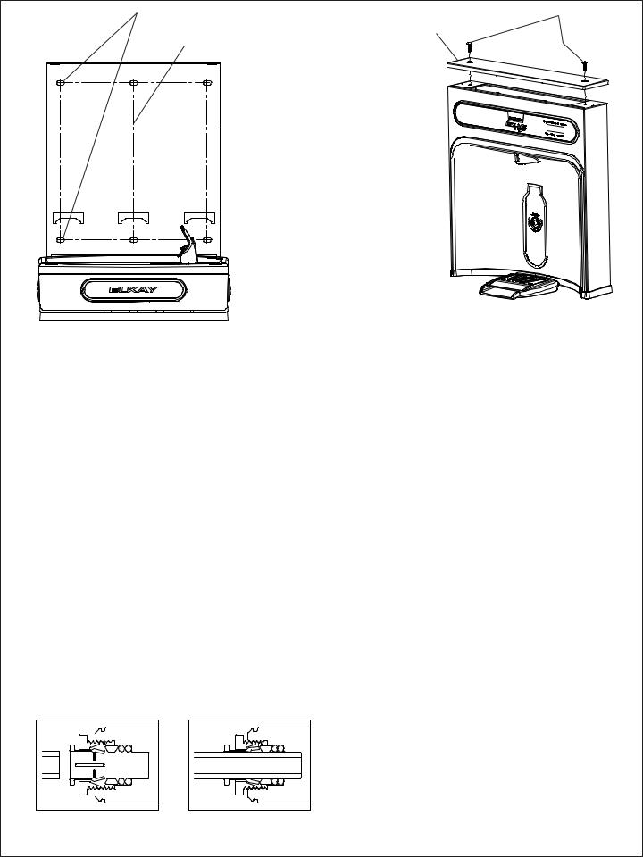
Fig. 3 |
BOTTLE FILLER INSTALLATION |
Fig. 4 |
|
|
|
|
|
|
|
|
1) |
Remove two (2) mounting screws with 5/32” allen wrench holding top cover to Bottle Filler (See FIG. 4). Remove top cover. Note do not discard mounting |
||||
|
screws, they will be needed to reinstall top cover.. |
|
|
|
|
2) |
Remove wall mounting plate from Bottle Filler. Place Wall plate against wall on top of EZ basin. Center the wall plate side to side with the EZ basin. Mark |
||||
|
the six (6) mounting holes with a pencil (See FIG. 3). |
|
|
|
|
3) |
Remove wall mounting plate from wall. NOTE: Mounting plate MUST be supported securely. Add fixture support carrier if wall will not provide adequate |
||||
|
support. |
|
|
|
|
4) |
Install wall mounting plate to wall using six (6) 7/16” obround mounting holes (mounting bolts not included) (See FIG. 3). Use appropriate fasteners for |
||||
|
your wall type. |
|
|
|
|
5) |
Locate plastic bushing (provided) and place in basin hole by pushing into hole until it snaps into place. This bushing protects the water line, wire(s), |
||||
|
and power cord from sharp edge of basin. This part must be used. |
|
|
||
6) |
Place Drain Mat into position on the bottom of the Bottle Filler Unit. |
|
|
||
7) |
Fish the purple wire (single units) or the purple and yellow wires (two-level units) up through basin hole. |
|
|
||
8) |
For Single Model installations: Attach the purple wire from cooler to the purple wire on the back of the unit, (Note yellow wire is not used). |
|
|||
8a) |
For Two-Level model installations: Attach the purple and yellow wires from coolers to the purple and yellow wires on the back of the unit, |
purple to |
|||
|
purple, yellow to yellow. |
|
|
|
|
9) |
Remove 3/8” to 1/4” reducing union from end of waterline, (do not throw away it will be needed later). Lay Bottle Filler on water cooler basin and cut |
||||
|
insulation from tube even with bottom of unit, remove this insulation from the 3/8” tube, but do not discard. Fish the power cord, and waterline through |
||||
|
the hole on top of water cooler created from the “Water Cooler Preparation” section. NOTE: To prevent scratching the basin place a towel or soft cloth over |
||||
|
the entire basin when working above it. |
|
|
|
|
10) |
With the power cord, wire(s), and waterline through hole on top of water cooler place Bottle Filler on the three (3) angled tabs protuding from the wall |
||||
|
mounting plate, installed on wall (See Fig. 9). Make sure rubber Drain Mat is installed properly on bottom of Bottle filler (See Cover Illustration). |
||||
11) |
Once Bottle Filler is installed on wall plate tabs, drain mat, water line, wire(s) and power cord are installed properly, push top of Bottle Filler toward |
||||
|
wall and line up top cover two (2) holes. |
|
|
|
|
12) |
Reinstall Top Cover on Bottle Filler (See FIG. 4) with two mounting screws from step 1 above. Caution do not over tighten screws. |
|
|||
13) |
Install remaining tube insulation to the water line from bottle filler, connect Bottle Filler waterline inside of the water cooler by |
|
|||
|
connecting the 3/8” water line with the 3/8” to 1/4” union and short piece of poly tube that was previously installed to the tee. |
|
|||
14) |
Turn water supply on and inspect for leaks. Fix all leaks before continuing. |
|
|
||
15 |
Once unit has been inspected for leaks and any leaks found corrected plug Bottle Filler and EZ unit into wall. Be sure to reinstall fuse to the circuit or |
||||
|
switch the circuit breaker back to the “ON” position. |
|
|
|
|
16) |
Once power is applied to Bottle Filler, the LCD Bottle Counter should illuminate . |
|
|
||
17) |
Verify proper dispensing by placing cup, hand, or any opaque object infront of sensor area and verify water dispenses. |
Note: the first intitial dispenses |
|||
|
might have air in line which may cause a sputter. This will be eliminated once all air is purged from the line. |
|
|
||
18) |
Once unit tests out, install Lower Panel back on EZ water cooler(s). Units are now ready for use. |
|
|
||
Note: Screw the locknut hand tight to seal |
|
Fig. 5 |
Fig. 6 |
Page 3 |
98706C (Rev. D - 9/11) |

|
EZS8WS*1A EZS8WS*2A |
EZS8WS*3A EZSDWS*1A |
|
|
EZSTL8WS*1A |
EZSTLR8WS*1A EZSTL8WS*2A EZSTL8WS*3A EZSTLDWS*1A |
|
|
|
BF6-BF7-BF8 PROGRAMS |
|
|
|
SETTING THE CONTROL BOARD |
|
|
VERIFY CONTROL BOARD SOFTWARE |
RESETTING BOTTLE COUNT |
|
1) |
To verify the software program of the control board the |
1) Depress the program button for approximately 2 seconds |
|
|
unit will need to be shut down and restarted. The chiller |
until the display changes then release. The display will |
|
|
(if present) does not need to be shut down and restarted. |
change and scroll through two messages: |
|
2) |
The units lower panel must be open to access the power |
“RST FLTR” – Reset Filter Status LED |
|
|
cord and wall outlet. |
|
“RST BCNT” – Reset Bottle Count |
3) |
Shut down the unit by unplugging the power cord from the |
“RNG SET” – Range Set for IR Sensor |
|
|
wall outlet. |
|
If the program button is not pushed again the display |
4) |
Restart the unit by plugging the power cord back into the |
will scroll through the two messages above for |
|
|
wall outlet. |
|
three cycles and then default back to bottle count |
5) |
Upon start up the bottle count display will show the |
and be back in run mode. |
|
|
software designation of BF6, BF7, BF8 or BF9. |
2) When the display changes to "RST BCNT", depress the |
|
6) |
Reference the BF6-BF7-BF8 or BF9 instructions for setting |
button again. The display will change to show current |
|
|
the control board. |
|
bottle count value i.e. "BC0033183". |
|
ACCESSING THE PROGRAMING BUTTON |
3) Depress the button again and the display will change to |
|
|
"BTLCT=0" for approximately 2 seconds and then return |
||
1) |
To access the program button remove the top cover of |
to run mode displaying 000000. |
|
|
the bottle filler. Remove the |
two (2) screws holding top |
4) You can test the bottle counter by running water |
|
cover to bottle filler with a 5/32” allen wrench . Remove |
approximately 5 seconds to see bottle counter advance 1. |
|
|
top cover. Do not discard mounting screws, they will be |
|
|
|
needed to reinstall the top cover after programming |
|
|
|
operations are completetd. The programming button is |
|
|
|
loacted at the top right side of the unit on the control board. |
|
|
|
RESET THE FILTER MONITOR |
|
|
1) |
Instructions apply to filtered units only. |
|
|
2) |
Depress the program button for approximately 2 seconds |
|
|
|
until the display changes then release. The display will |
|
|
|
change and scroll through three messages: |
|
|
|
“RST FLTR” – Reset Filter Status LED |
|
|
|
“RST BCNT” – Reset Bottle Count |
|
|
|
“RNG SET” – Range Set for IR Sensor |
|
|
|
If the program button is not pushed again the display |
|
|
|
will scroll through the three messages above for |
|
|
|
three cycles and then default back to bottle count and |
|
|
|
be back in run mode. |
|
|
3) |
When the display changes to "RST FLTR", depress |
|
|
|
the button again. The display will change to show |
|
|
|
"FLT=". Depress the button again and the display will |
|
|
|
show "FLTR=0". |
|
|
4) The green LED should now be illuminated indicating |
|
||
|
that the visual filter monitor has been reset. |
|
|
|
SETTING RANGE OF THE IR SENSOR |
|
|
1) |
Depress the program button for approximately 2 seconds |
|
|
|
until the display changes then release. The display will |
|
|
|
change and scroll through three messages: |
|
|
|
“RST FLTR” – Reset Filter Status LED |
|
|
|
“RST BCNT” – Reset Bottle Count |
|
|
|
“RNG SET” – Range Set for IR Sensor |
|
|
2) |
If the program button is not pushed again the display |
|
|
|
will scroll through the two messages above for |
|
|
|
three cycles and then default back to bottle count |
|
|
|
and be back in run mode. |
|
|
3) |
When display shows “RNG SET” push program button |
|
|
|
once the display will show current value |
|
|
|
(can be 1 – 10) i.e. “RNG = 3”. |
|
|
4) |
Once display shows current value push the program |
|
|
|
button to scroll through value of 1 – 10. Select the |
|
|
|
desired range setting. |
|
|
5) |
Once range is selected allow approximately 4 seconds |
|
|
|
to pass and then the display will go back to bottle counter |
|
|
|
and be in run mode. |
|
|
6) |
Test bottle filler by placing bottle or hand in front of |
|
|
|
sensor to make sure water is dispensed. |
|
|
98706C (Rev. D - 9/11) |
Page 4 |
EZS8WS*1A EZS8WS*2A EZS8WS*3A EZSDWS*1A
EZSTL8WS*1A EZSTLR8WS*1A EZSTL8WS*2A EZSTL8WS*3A EZSTLDWS*1A
|
BF9 PROGRAM |
|
|
SETTING THE CONTROL BOARD |
|
|
VERIFY CONTROL BOARD SOFTWARE |
SETTING UNIT TYPE |
1) |
To verify the software program of the control board the |
1) Depress the program button for approximately 2 seconds |
|
unit will need to be shut down and restarted. The chiller |
until the display changes then release. The display will |
|
(if present) does not need to be shut down and restarted. |
change and scroll through two messages: |
2) |
The units lower panel must be open to access the power |
“RST FLTR” – Reset Filter Status LED |
|
cord and wall outlet. |
“SETTINGS” – System Settings Sub Menu |
3) |
Shut down the unit by unplugging the power cord from the |
If the program button is not pushed again the display |
|
wall outlet. |
will scroll through the two messages above for |
4) |
Restart the unit by plugging the power cord back into the |
three cycles and then default back to bottle count |
|
wall outlet. |
and be back in run mode. |
5) |
Upon start up the bottle count display will show the |
2) When the display changes to “SETTINGS”, depress |
|
software designation of BF6, BF7, BF8 or BF9. |
the button again. The display will change to show |
6) |
Reference the BF6-BF7-BF8 or BF9 instructions for setting |
“RNG SET“- Range set for IR sensor. |
|
the control board. |
“UNIT TYP“ - Type of unit (REFRIG or NON-RFRG) |
|
|
“RST BCNT“ - Reset bottle count |
|
ACCESSING THE PROGRAMING BUTON |
3) When display shows “UNIT TYPE” push program |
1) |
To access the program button remove the top cover of |
button once the display will show current value |
|
the bottle filler. Remove the two (2) screws holding top |
Can be REFRIG or NON-RFRG |
|
cover to bottle filler with a 5/32” allen wrench . Remove |
4) Push button once to change value. Once value is |
|
top cover. Do not discard mounting screws, they will be |
selected the display will show the new value. |
|
needed to reinstall the top cover after programming |
(Can be REFRIG or NON-RFRG) |
|
operations are completetd. The programming button is |
“REFRIG“ - stands for refrigerated product. In this |
|
loacted at the top right side of the unit on the control board. |
setting the flow rate is estimated at 1.0 gallon per minute. |
|
|
“NON-RFRG“ - stands for nonrefrigerated product. |
|
RESET THE FILTER MONITOR |
In this setting the flow rate is estimated |
1) |
Instructions apply to filtered units only. |
at 1.5 gallons per minute. |
2) |
Depress the program button for approximately 2 seconds |
Both “REFRIG“ and “NON-RFRG“ simulate |
|
until the display changes then release. The display will |
1 bottle equal to 20 oz. |
|
change and scroll through two messages: |
5) Allow approximately 4 seconds to pass and the display |
|
“RST FLTR” – Reset Filter Monitor |
will return to bottle counter and be in run mode. |
|
“SETTINGS” – System Settings Sub Menu |
RESETTING BOTTLE COUNT |
|
If the program button is not pushed again the display |
|
|
will scroll through the two messages above for |
1) Depress the program button for approximately 2 seconds |
|
three cycles and then default back to bottle count and |
until the display changes then release. The display will |
|
be back in run mode. |
change and scroll through two messages: |
3) When the display changes to “RST FLTR”, depress |
“RST FLTR” – Reset Filter Status LED |
|
|
the button again. The display will change to show |
“SETTINGS” – System Settings Sub Menu |
|
“FLTR =”. Depress the button again and the display |
If the program button is not pushed again the display |
|
will show “FLTR =0” |
will scroll through the two messages above for |
4) |
The Green LED should be illuminated indicating that |
three cycles and then default back to bottle count |
|
the visual filter monitor has been reset. |
and be back in run mode. |
|
2) When the display changes to “SETTINGS”, depress |
|
|
|
|
|
SETTING RANGE OF THE IR SENSOR |
the button again. The display will change to show |
|
“RNG SET“- Range set for IR sensor. |
|
1) |
Depress the program button for approximately 2 seconds |
“UNIT TYP“ - Type of unit (REFRIG or NON-RFRG) |
|
until the display changes then release. The display will |
“RST BCNT“ - Reset bottle count |
|
change and scroll through two messages: |
If the button is not pushed again the display will scroll |
|
“RST FLTR” – Reset Filter Status LED |
through the three messages above for the cycles and |
|
“SETTINGS” – System Settings Sub Menu |
return to run mode. |
|
If the program button is not pushed again the display |
3) When display shows “RST BCNT” push program button |
|
will scroll through the two messages above for |
once the display will show current value i.e. “0033183”. |
|
three cycles and then default back to bottle count |
4) Once display shows current value push the program |
|
and be back in run mode. |
button once more to reset back to 0. The display will |
2) When the display changes to “SETTINGS”, depress |
show BTLCT = 0 for approximately 2 seconds and |
|
|
the button again. The display will change to show |
then return to run mode showing 00000000 bottles. |
|
“RNG SET“- Range set for IR sensor. |
5) Testing the bottle counter: |
|
“UNIT TYP“ - Type of unit (REFRIG or NON-RFRG) |
REFRIG units: Place bottle or hand in front of sensor |
|
“RST BCNT“ - Reset bottle count |
for 9.4 seconds to see bottle counter count 00000001. |
3) |
When display shows “RNG SET” push program |
(This is based on filling a 20 oz. bottle) |
|
button once the display will show current value |
NON-RFRG units: Place bottle or hand in front of sensor |
|
(can be 1 – 10) i.e. “RNG = 3”. |
for 6.25 seconds to see bottle counter count 00000001. |
4) |
Once display shows current value push the |
(This is based on filling a 20 oz bottle) |
|
program button to scroll through value of 1 – 10. |
|
|
Select the desired range setting. |
|
5) |
Once range is selected allow approximately |
|
|
4 seconds to pass and then the display will go |
|
|
back to bottle counter and be in run mode. |
|
6) |
Test bottle filler by placing bottle or hand in front |
|
|
of sensor to make sure water is dispensed. |
|
|
|
|
|
Page 5 |
98706C (Rev. D - 9/11) |
 Loading...