


EZWSR*1B
INSTALLATION, CARE & USE MANUAL
EZWSRK -EZH2O T M RETRO-FIT BOTTLE FILLING UNIT
IMPORTANT
THIS IS AN INDOOR APPLICATION ONLY.
ALL SERVICE TO BE PERFORMED BY AN
AUTHORIZED SERVICE PERSON.
TOOLS REQUIRED
BUT NOT PROVIDED:
SAFETY GLASSES
GLOVES
1-3/8” HOLE PUNCH (PROVIDED) 1/2” DRILL BIT
ELECTRIC DRILL
3/4” WRENCH OR CRESCENT WRENCH 5/16” NUT DRIVER
UTILITY KNIFE
TAPE MEASURE
PENCIL
CENTER PUNCH
1/2” SOCKET & RATCHET WRENCH 5/32” ALLEN WRENCH
7/64” ALLEN WRENCH
IMPORTANT! INSTALLER PLEASE NOTE.
THE GROUNDING OF ELECTRICAL EQUIPMENT SUCH AS TELEPHONE, COMPUTERS, ETC. TO WATER LINES IS A COMMON PROCEDURE. THIS GROUNDING MAY BE IN THE BUILDING OR MAY OCCUR AWAY FROM THE BUILDING. THIS GROUNDING CAN CAUSE ELECTRICAL FEEDBACK INTO A FOUNTAIN, CREATING AN ELECTROLYSIS WHICH CAUSES A METALLIC TASTE OR AN INCREASE IN THE METAL CONTENT OF THE WATER. THIS CONDITION IS AVOIDABLE BY USING THE PROPER MATERIALS AS INDICATED. ANY DRAIN FITTINGS PROVIDED BY THE INSTALLER SHOULD BE MADE OF PLASTIC TO ELECTRICALLY ISOLATE THE FOUNTAIN FROM THE BUILDING PLUMBING SYSTEM. WE SUGGEST THAT THE BOTTLE FILLING STATION AND WATER COOLER BE PROTECTED BYAGROUND FAULT CIRCUIT INTERRUPTER (GFCI).
INSTALLER
EZWSR Bottle Fillers are among the easiest to install on the market today. To insure you install these models easily and correctly, PLEASE READ THESE SIMPLE INSTRUCTIONS BEFORE STARTING THE INSTALLATION. CHECK YOUR INSTALLATION FOR COMPLIANCE WITH PLUMBING, ELECTRICAL, AND OTHER APPLICABLE CODES. After installation, leave these instructions with the Cooler for future reference.
Page 1 |
98705C (Rev. D - 9/11) |
EZWSR*1B
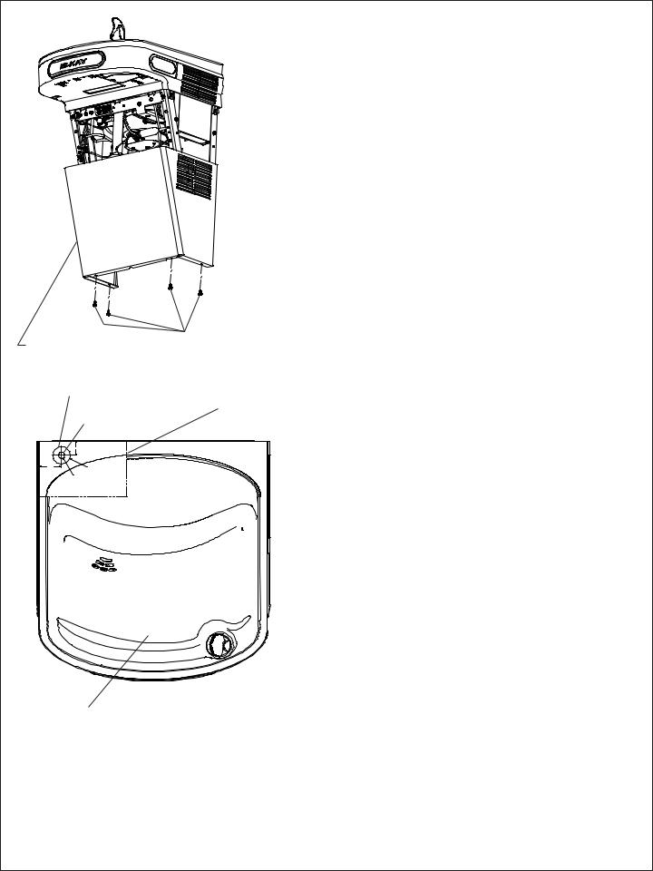
LOWER COVER |
|
SCREWS |
|
|
|
||
|
|
Fig. 1 |
|
|
1-3/8” DIA. HOLE |
|
|
|
|
|
PAPER |
|
1/2” DIA. HOLE |
TEMPLATE |
|
|
|
||
|
WALL |
|
|
|
1 1/8" |
|
|
1 3/4" |
1-3/8"O |
|
|
|
PUNCHED |
|
|
|
HOLE |
|
|
|
1/2"O |
|
|
|
PILOT |
|
|
SIDE |
HOLE |
|
|
EZH20 RETRO-FIT BOTTLE |
|
|
|
LEFT |
FILLER |
|
|
BASIN HOLE TEMPLATE |
|
|
|
WATER COOLER PREPARATION
1)Remove lower front panel of watercooler by removing the four (4) screws from the bottom of cooler. (See FIG. 1) NOTE: For Two Level Models the Bottle Filling Unit should be mounted to the higher unit. Both lower front panels and basin assemblies will need to be removed.
1a) For units with model no’s. ending with 1, 1A, 2 or 3 these units will need to be removed from the wall in order to remove the basin assembly(s).
2)Power OFF circuit that the water cooler is connected to by switching the circuit breaker to the “OFF” position or by removing the fuse to the circuit. Remove the water cooler plug from the outlet and shut off water supply.
3)Cut out the Drain Mat template located on the last page of the manual and place the template on rear left side of the EZ cooler basin.
4)Locate 1-3/8” diameter hole on left side of the template (See FIG. 2). Mark center of hole on basin with pencil.
5)Remove Basin Assembly by loosening four (4) screws two on each side of cooler as shown in Fig. 5. Disconnect water line “A” from bubbler at the evaporator tank (See Fig. 3). NOTE: When disconnecting water lines use a container to catch any water running out of the lines. Disconnect basin assembly from drain trap. Lift basin assembly straight up to remove, and disconnect two wires from push bar switches. (Note: This will allow easier assembly of water filter to unit and pressurization of the unit.)
5a) For units referenced in step “1a”. Remove Basin Assembly by loosening four (4) screws two on each side of cooler as shown in Fig. 5. Remove 2 screws from top back of unit to remove the “L” bracket. Remove 1 screw from left side of cross brace in front of unit that retains the drain support. Disconnect water line “A” from regulator at the evaporator tank (See Fig. 3B). NOTE: When disconnecting water lines use a container to catch any water running out of the lines. Disconnect basin assembly from drain trap. Lift basin assembly straight up to remove, and disconnect two wires from push bar switches.
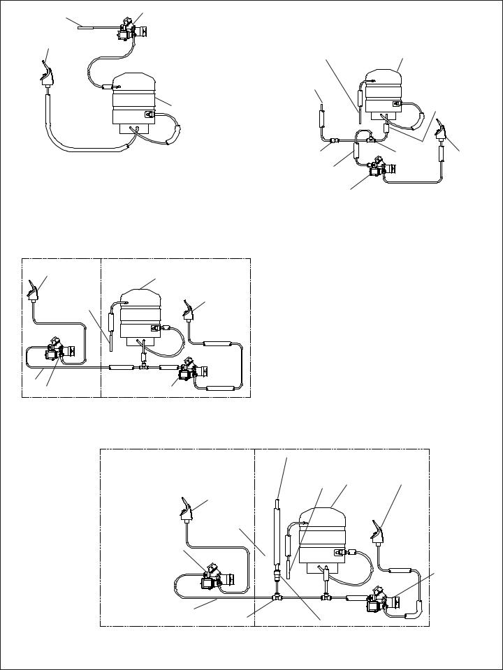
PRESSURIZATION OF WATER SYSTEM
NOTE: This proceedure MUST be performed on ALL SINGLE EZ WATER COOLERS or the bottle filling unit WILL NOT perform properly!
1) Remove water inlet (B) and outlet (C) from solenoid valve (See Fig. 3 or 3B). NOTE: When disconnecting water lines use a container to catch any water running out of the lines.
2) CAUTION: If supply pressure will ever exceed 100 psi, install a pressure regulator to limit the inlet pressure to the filter to 100 psi or below.
DO NOT ATTACH HOT WATER LINE TO FILTER.
3) Reonnect the water inlet to the inlet of the evaporator (See Fig. 4 or 4B).
4) Cut a 12” long piece of poly tube (besure to insulate poly tube with supplied insulation tubing) and insert one end into the outlet side of the evaporator “D” (See Fig. 4 or 4B), connect Tee to other end of tube.
5) Cut a 12” long piece of poly tube (besure to insulate poly tube with supplied insulation tubing) and insert into the Tee and the other end into the inlet side of the solenoid valve “E” (See fig. 4 or 4B).
EZBASIN
TWO-LEVEL MODIFICATION OF WATER SYSTEM NOTE: Two-Level water systems are already plumbed for pressurization.
STANDARD TWO-LEVEL MODELS
Follow instruction 2 thru 4 under “Pressurization of water system” to attach filter to water system. The non-refrigerated side must be removed from the wall in order to remove the basin assy. and install the filter head assy.
1) Remove the Two-Level Cover Plate from the right hand side of the non-refrigerated unit in order to access the rear Basin Assy. screw. 2) Cut poly tube “H” between the existing tee and the solenoid valve of the L.H. unit.
3) Insert supplied 1/4” Tee in water line “H” where it was just cut (See Fig. 4A).
TWO-LEVEL REVERSED MODELS
Follow instruction 2 thru 4 under “Pressurization of water system” to attach filter to water system. The non refrigerated side must be removed from the wall in order to remove the basin assy. and install the filter head assy.
1) Remove the Bi-Level Cover Plate from the left hand side of the refrigerated unit in order to access the rear Basin Assy. screw (See Fig 5). 2) Cut poly tube “H” approximately 3” from the left side of the existing tee.
3) Insert supplied 1/4” tee in water line “H” where it was just cut.
98705C (Rev. D - 9/11) |
Page 2 |
EZWSR*1B
Water Inlet |
B |
Solenoid Valve |
|
||
Bubbler |
|
C |
|
|
Evaporator
A
EZ Non-Pressurized
Plumbing Diagram
Fig. 3
L.H. Non-Refrig unit |
R.H. Refrig. unit |
Bubbler |
Evaporator |
|
|
Water Inlet |
Bubbler |
|
H |
Solenoid Valve |
Solenoid Valve |
|
Water Inlet |
Evaporator |
|
|
3/8” Water Line |
|
|
|
from Bottle |
|
|
|
Filling Unit |
|
|
|
|
|
D |
Tube Insulation |
|
|
|
|
G |
|
|
|
3/8” To 1/4” Union |
E |
1/4” Tee |
Bubbler |
Tube Insulation |
|
|
|
|
|
|
|
Solenoid Valve |
|
F |
|
|
|
|
|
EZ Plumbing Diagram after
Pressurization Modifications
Fig. 4
Standard EZ Two Level
Pressurized Plumbing Diagram
Fig. 3A
L.H. Non-Refrig unit |
R.H. Refrig. unit |
|
|
|
3/8” Water Line from |
|
|
|
Bottle Filling Unit |
|
|
|
Water Inlet |
Evaporator |
Bubbler |
|
|
||
Bubbler
1/4” Union
Solenoid Valve
Solenoid Valve
H |
1/4” Tee |
|
|
3/8” To 1/4” Union |
EZ Two Level Plumbing Diagram after
Bottle Filler Water Line Addition
Fig. 4A
Page 3 |
98705C (Rev. D - 9/11) |

EZWSR*1B
Plumbing Diagrams for EZ Coolers w/model no’s ending with 1, 1A, 2, & 3
Water Inlet
|
|
Solenoid Valve |
|
|
||
Bubbler |
B |
C |
Bubbler |
|
Water Inlet |
|
|
|
|
|
|
||
|
Regulator |
|
|
|
Evaporator |
|
|
|
|
Regulator |
|||
|
|
|
|
|||
|
|
|
Evaporator |
|
Solenoid Valve |
|
|
|
|
|
|
||
|
|
|
|
|
1/4” Tee |
|
|
|
|
|
|
D |
|
|
|
|
|
F |
E |
|
|
|
A |
3/8” Water Line from |
|
|
|
|
|
|
|
|
||
|
|
|
Bottle Filling Unit |
|
Tube Insulation |
|
|
|
|
|
|
||
EZ Non-Pressurized |
|
3/8” To 1/4” Union |
||||
EZ Plumbing Diagram after |
||||||
|
Plumbing Diagram |
|
||||
|
|
Pressurization Modifications |
||||
|
Fig. 3B |
|
|
|||
|
|
|
|
Fig. 4B |
||
|
|
|
|
|
||
L.H. Non-Refrig unit |
|
R.H. Refrig. unit |
|
|
||
|
Regulator |
|
Regulator |
|
|
|
Bubbler |
Evaporator |
|
|
|
Bubbler |
Solenoid Valve
Water Inlet |
H |
Solenoid Valve |
Standard EZ Two Level
Pressurized Plumbing Diagram
Fig. 3C
L.H. Non-Refrig unit |
R.H. Refrig. unit |
|
|
3/8” Water Line from |
Regulator |
|
Bottle Filling Unit |
|
|
|
|
Regulator |
Water Inlet Evaporator |
Bubbler |
|
|
|
Bubbler |
|
|
1/4” Union |
|
|
Solenoid Valve |
H |
|
|
|
|
3/8” To 1/4” Union |
1/4” Tee |
|
Solenoid Valve
EZ Two Level Plumbing Diagram after Bottle Filler Water Line Addition
Fig. 4C
98705C (Rev. D - 9/11) |
Page 4 |
 Loading...