

Page 1

Troubleshooting Guide
Fuller Heavy Duty Tr
TRTS0020 EN-US
October 2007
RT-11109A-AT
RT-11109A-ATR
RT-11109A-ATS
RT-12109A-AT
RT-14109A-ATS
RTO-11109A-AT
RTO-11109A-ATS
RTO-11109B-AT
RTO-11109B-ATE
RTO-11109B-ATR
RTO-11109B-ATS
RTO-12109A-AT
RTO-12109B-AT
RTO-13109A-ATE
RTO-13109B-AT
RTO-13109B-ATE
RTO-14109A-ATE
RTO-14109A-ATS
RTO-14109B-AT
RTO-14109B-ATE
RTO-14109B-ATS
RTO-16109A-AT
RTO-16109A-ATE
RTO-16109B-AT
RTO-16109B-ATE
RTO-9109A-AT
RTO-9109B-AT
ansmissions
Page 2

For parts or service call us
Pro Gear & Transmission, Inc.
1 (877) 776-4600
(407) 872-1901
parts@eprogear.com
906 W. Gore St.
Orlando, FL 32805
Page 3

General Warnings:
Before starting a vehicle:
• Sit in the driver’s seat
• Place shift lever in neutral
• Set the parking brake
Before working on a vehicle or leaving the cab with
engine running:
• Place shift lever in neutral
• Set the parking brake
• Block the wheels
Do not release the parking brake or attempt to select a
gear until the air pressure is at the correct level.
When parking the vehicle or leaving the cab:
• Place shift lever in neutral
• Set the parking brake
OTC Tool & Equipment Division,
SPX Corporation
Eaton Part No. Description
5505027 Volt /Ohm Meter (Standard
commercially available VOM)
For ordering in U.S. and Canada call 1-800-533-0492. (In
Minnesota call 507-455-7010.)
MPSI Micro Processor Systems, Inc.
MPSI Part No. Description
104004 Pro-link Main (MPSI hand-held diagnostic
tool)
205040 Heavy Duty Multi-Protocol Cartridge (MPC)
805001 MPC Eaton Systems Software
For MPSI phone orders call 1-800-639-6774.
To avoid damage to the transmission during towing:
• Place shift lever in neutral
• Lift the drive wheels off of the ground or
disconnect the driveline
Do not operate vehicle if alternator lamp is lit or if gauges
indicate low voltage.
Suggested Tools:
Pressure Gauges:
• 0-300 PSI Hydraulic gauge
• 0-100 PSI Hydraulic gauge
• 0-100 PSI Air gauge
Related Publications
Installation Guide - Eaton TRIG-0020
Driver Instructions - Eaton TRDR-0020
Service Manual - Eaton TRSM-0020
Illustrated Parts List - Eaton TRIP-0023 (11109)
Eaton TRIP-0025 (13109)
Eaton TRIP-0022 (14109)
Eaton TRIP-0026 (16109)
For more information call 1-800-826-HELP (826-4357).
Every effort has been made to ensure the accuracy of all information in this manual. However, Eaton Transmission Division makes no expressed or implied warranty or representation
based on the enclosed information. Any errors or omissions may be reported to Training and Publications, Eaton Transmission Division, P.O. Box 4013, Kalamazoo, MI 49003.
Page 4

Table of Contents
Section 1: Introduction
Diagnostics Procedure ............................................... 1-2
Fault Codes Retrieval/Clearing..................................... 1-3
Driving Techniques ..................................................... 1-4
Fault Code Isolation Procedure Index .......................... 1-8
Symptom Driven Diagnostics ................................... 1-10
Section 2: Fault Isolation Procedures
Pretests
Electrical Pretest ......................................................... 2-1
Pneumatic Pretest ...................................................... 2-3
Power-Up Sequence Test ........................................... 2-4
Component and System Codes
Component Code 11, ECU .......................................... 2-6
Component Code 14, Shift Lever Fault ........................ 2-8
Component Code 15, Shift Lever Data Link ............... 2-10
Component Code 21, Interrupt Solenoid Coil ............. 2-16
Component Code 22, Lockup/Bypass
Solenoid Coil ............................................................ 2-18
Component Code 23, Engine Speed Sensor .............. 2-20
Component Code 24, Hydraulic System Fault ............ 2-24
Component Code 31, Engine Brake Relay Coil ........... 2-28
Component Code 32, Defuel Solenoid Coil ................ 2-32
Component Code 33, System Voltage ....................... 2-36
Component Code 43, Range Solenoid Coil ................ 2-50
Component Code 44, Disc/Inertia Brake
Solenoid Coil ............................................................ 2-52
Component Code 45, Power Synchronizer
Band/Engine Boost Solenoid Coil .............................. 2-54
Component Code 51, Center Rail Sensor................... 2-56
Component Code 52, Neutral Sensor ........................ 2-60
Component Code 53, Gear Engaged Sensor .............. 2-64
Component Code 54, HI Range Sensor ..................... 2-68
Component Code 55, LO Range Sensor .................... 2-72
Component Code 56, Input Speed Sensor ................. 2-76
Component Code 57, Output Speed Sensor .............. 2-80
Component Code 61, Autoshifter Solenoid 1
Coil .......................................................................... 2-84
Component Code 62, Autoshifter Solenoid 2
Coil .......................................................................... 2-86
Component Code 63, Autoshifter Solenoid 3
Coil .......................................................................... 2-88
Component Code 64, Autoshifter Solenoid 4
Coil .......................................................................... 2-90
System Code 71, Stuck Engaged .............................. 2-92
System Code 72, Failed to Select a Rail ..................... 2-96
System Code 73, Failed to Engage Gear .................. 2-100
System Code 74, Failed to Synchronize ................... 2-104
System Code 81, Invalid Shift Lever at Start
(Cable Only) ........................................................... 2-108
Component Code 34, Throttle Position Sensor .......... 2-38
System Code 35, Engine Control Failure
(Mechanically-Governed Engines) ............................. 2-42
System Code 35, Engine Control Failure
(Electronically-Governed Engines) ............................ 2-44
System Code 41, Range Failed to Engage .................. 2-48
Component Code 82, Multiple Non-Adjacent Senors
(Cable Only) ........................................................... 2-110
System Code 83, Shift Lever Missing
(Cable Only) ........................................................... 2-112
Component Code 83, Shift Lever Missing
(Electronic Only)..................................................... 2-114
1-1
Page 5

Table of Contents
Section 3: Symptom Isolation Procedures
Symptom Pretests
Transmission Basic Inputs Pretest .............................. 3-1
Engine Interface Pretest .............................................. 3-5
Symptom Tests
Shift Complaint Test ................................................... 3-7
High Operating Temperature Test ............................. 3-14
Hand-Held Diagnostic Tool Failed to Operate Test ..... 3-17
Shift Lever in Gear Signal Test .................................. 3-20
Neutral Output Test .................................................. 3-22
Splitshaft PTO Switch Test........................................ 3-24
Quick to Neutral Test ................................................ 3-26
Shift Lever Auxiliary Output 2 Test ............................ 3-27
Shift Lever Auto Neutral Input Test ........................... 3-29
Shift Lever Back Light Test ....................................... 3-30
Appendix
Torque Converter Hydraulic Diagram .......................... A-1
Pneumatic Diagram AT, ATR and ATS ......................... A-2
Pneumatic Diagram ATE ............................................. A-3
Pneumatic Diagram
Mechanical ATE with Throttle Boost ............................ A-4
Cable Shift Lever Wiring Diagram ............................... A-6
Single Station Electronic Shift Lever Wiring Diagram ... A-8
Dual Station Electronic Shift Lever Wiring Diagram ... A-10
Cable Shift Lever Adjustment Procedure ................... A-12
Linear Throttle Position Adjustment Procedure ......... A-14
Electro-Pneumatic Defuel Control
Adjustment Procedure .............................................. A-15
Dual Station Start Enable .......................................... A-16
Reverse Relay Indicator Test ..................................... 3-31
Start Enable Relay Test ............................................. 3-34
Start Enable Relay Latch Test .................................... 3-40
Shift Lever Voltage Test (Driver Lever) ...................... 3-42
Shift Lever Voltage Test (Work Lever) ....................... 3-44
1-2
Page 6

1-1
Page 7
Introduction
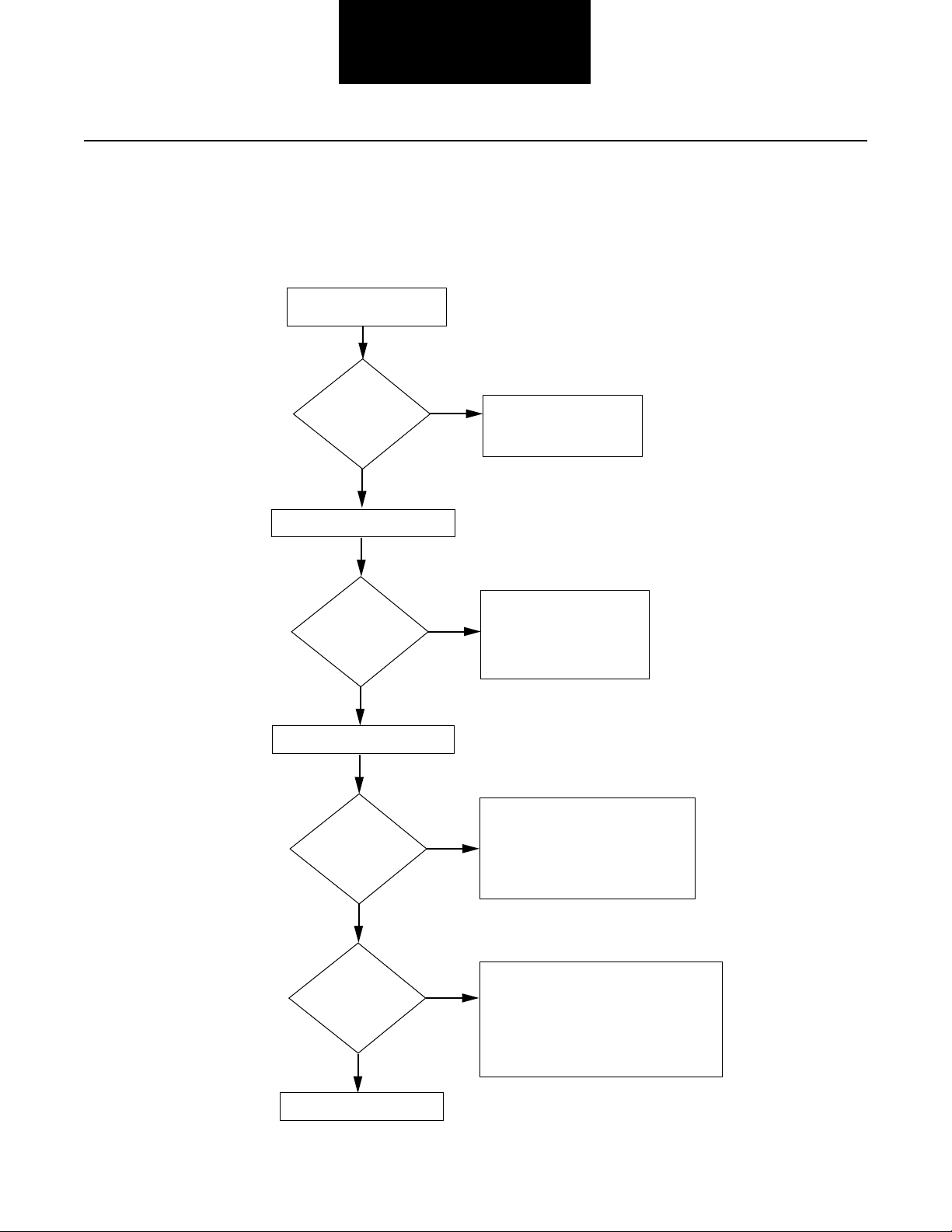
Diagnostics Procedure
Follow the flowchart below for all CEEMAT transmission failures. Perform tests and procedures as directed by the flowchart.
Key on.
Failure detected
during self-check?
NO
Retrieve active codes. (Page 1-3)
Active codes?
NO
Retrieve inactive codes. (Page 1-3)
Inactive codes?
NO
YES
YES
YES
• Perform Electrical Pretest
(Page 2-1)
• Perform Power-Up
Sequence Test (Page 2-4)
• Refer to the Fault Code
Isolation Procedure Index
(Page 1-8) to select a fault
code isolation procedure
• Perform Electrical Pretest
(Page 2-1)
• Record and clear codes (Page 1-3)
• Refer to the Fault Code Isolation
Procedure Index (Page 1-8) to
select a fault code isolation
procedure
• Perform Electrical Pretest (Page 2-1)
• Perform Pneumatic Pretest (Page 2-3)
1-2
Symptom?
NO
Test complete.
YES
• Perform Electrical Pretest (Page 2-1)
• Perform Pneumatic Pretest (Page 2-3)
• Perform Transmission Basic Inputs
Pretest (Page 3-1)
• Perform Engine Interface Pretest (Page 3-5)
• Refer to Symptom Driven Diagnostics
Table (Page 1-10) to select a fault
isolation procedure
Page 8

Introduction
Fault Codes Retrieval/Clearing
Retrieving Fault Codes
Retrieve CEEMAT fault codes by enabling the CEEMAT
system’s self-diagnostic mode.
Note: You can also use a diagnostic scan tool, such as the
MPSI Pro Link Main, to retrieve CEEMAT fault codes. Refer to
the OEM’s documentation for more information.
1. Place the shift lever in neutral.
2. Set the parking brakes.
3. Turn the ignition key on but do
4. To Retrieve Active Codes: Start with the key in the on
position. Turn the key off and on two times within five
seconds ending with the key in the on position.
2 times
off
not
start the engine.
on
Clearing Fault Codes
The following procedure clears all inactive (intermittent) fault
codes from the ECU’s memory. (Active fault codes are
automatically cleared when the fault has been corrected.)
1. Place the shift lever in neutral.
2. Set the parking brakes.
not
3. Turn the ignition key on but do
4. Start with the key in the on position. Turn the key off
and on six times within five seconds ending with the
key in the on position.
6 times
off
start the engine.
on
Fault Codes Retrieval/Clearing
Diagnostics Procedure
To Retrieve Inactive (Intermittent) Codes: Start with
the key in the on position. Turn the key off and on four
times within five seconds ending with the key in the on
position.
4 times
off
After a brief pause, the service transmission indicator
lamp begins flashing two-digit fault codes.
5. Observe the sequence of flashes on the indicator lamp
and record the codes. A one to two second pause
separates each stored code, and the sequence automatically repeats after all codes have been flashed.
2 Flashes 1 Flash
on
Short
pause
(1/2 sec)
(1–2 sec)
3 Flashes 1 Flash
Short
pause
(1/2 sec)
Code 21 Code 31
1-3
Page 9

Driving Techniques
Introduction
Fault
Codes
11 ECU Component Key on. If the fault is present, the system should
14 Shift Lever Fault Component Key on. If the fault is present, the system should
15 Shift Lever Data Link Component Key on. If the fault is present, the system should
21 Interrupt Solenoid Coil Component Key on. If the fault is present, the system should
Description Type of Code Driving Technique
automatically detect the problem and set the code.
If the fault is not present at key on, operate the vehicle and
attempt to duplicate the driving conditions that triggered
the fault code. Possible triggers include heat and vibration.
automatically detect the problem and set the code.
If the fault is not present at key on, operate the vehicle and
attempt to duplicate the driving conditions that triggered
the fault code. Possible triggers include heat, vibration and
selecting different shift lever positions.
automatically detect the problem and set the code.
If the fault is not present at key on, operate the vehicle and
attempt to duplicate the driving conditions that triggered
the fault code. Possible triggers include heat and vibration.
automatically detect the problem and set the code.
If the fault is not present at key on, operate the vehicle and
attempt to duplicate the driving conditions that triggered
the fault code. Possible triggers include heat and vibration.
22 Lockup/Bypass Solenoid Component Key on. If the fault is present, the system should
Coil automatically detect the problem and set the code.
If the fault is not present at key on, operate the vehicle and
attempt to duplicate the driving conditions that triggered
the fault code. Possible triggers include heat and vibration.
23 Engine Speed Sensor Component Operate the vehicle above 4th gear until the fault occurs.
Maintain a steady speed. If may be necessary to operate
the vehicle for a prolonged period of time if the cause of
the failure is related to heat or vibration.
24 Hydraulic System Fault Component Complete several automatic shifts while driving the vehicle
through terrain that loads the engine.
31 Engine Brake Relay Coil Component Key on. If the fault is present, the system should
automatically detect the problem and set the code.
If the fault is not present at key on, operate the vehicle and
attempt to duplicate the driving conditions that triggered
the fault code. Possible triggers include heat and vibration.
32 Defuel Solenoid Coil Component Key on. If the fault is present, the system should
automatically detect the problem and set the code.
If the fault is not present at key on, operate the vehicle and
attempt to duplicate the driving conditions that triggered
the fault code. Possible triggers include heat and vibration.
1-4
Page 10

Introduction
Driving Techniques, continued
Fault
Codes
33 System Voltage Component Key on. If the fault is present, the system should
34 Throttle Position Sensor Component Key on. If the fault is present, the system should
35 Engine Control Failure System Operate the vehicle and shift the transmission up and down
Description Type of Code Driving Technique
automatically detect the problem and set the code.
If the fault is not present at key on, operate the vehicle and
attempt to duplicate the driving conditions that triggered
the fault code. Possible triggers include heat and vibration.
automatically detect the problem and set the code.
If the fault is not present at key on, operate the vehicle and
attempt to duplicate the driving conditions that triggered
the fault code. Possible triggers include heat, vibration and
varying levels of throttle demand.
(Mechanically-Governed through the gears.
Engines)
Driving Techniques
35 Engine Control Failure System Key on. If the fault is present, the system should
(Electronically-Governed automatically detect the problem and set the code.
Engines) If the fault is not present at key on, operate the vehicle and
attempt to duplicate the driving conditions that triggered
the fault code. Possible triggers include heat, vibration and
varying levels of throttle demand.
41 Range Failed to Engage System Operate the vehicle and perform several range upshifts
and downshifts. The failure is detected after 5 consecutive
attempts to complete the same type of range shift. Several
shifts (ten or more) may be necessary before the ECU
confirms the failure.
43 Range Solenoid Coil Component Key on. If the fault is present, the system should
automatically detect the problem and set the code.
If the fault is not present at key on, operate the vehicle and
attempt to duplicate the driving conditions that triggered
the fault code. Possible triggers include heat and vibration.
44 Disc/Inertia Brake Coil Component Key on. If the fault is present, the system should
automatically detect the problem and set the code.
If the fault is not present at key on, operate the vehicle and
attempt to duplicate the driving conditions that triggered
the fault code. Possible triggers include heat and vibration.
45 Power Synchronizer Component Key on. If the fault is present, the system should
Band/Engine Boost automatically detect the problem and set the code.
Solenoid Coil If the fault is not present at key on, operate the vehicle and
attempt to duplicate the driving conditions that triggered
the fault code. Possible triggers include heat and vibration.
51 Center Rail Sensor Component Complete several front box gear shifts, including
selections from NEUTRAL and automatic shifts while
in motion.
1-5
Page 11

Driving Techniques, continued
Introduction
Fault
Codes
52 Neutral Sensor Component Complete several front box gear shifts, including
53 Gear Engaged Sensor Component Complete several front box gear shifts, including
54 HI Range Sensor Component Complete several range shifts up and down across the
55 LO Range Sensor Component Complete several range shifts up and down across the
56 Input Speed Sensor Component Select a forward gear and drive at a steady speed for
57 Output Speed Sensor Component Select a forward gear and drive at a steady speed for
61 Autoshifter Solenoid 1 Component Key on. If the fault is present, the system should
Description Type of Code Driving Technique
selections from NEUTRAL and automatic shifts while in
motion.
selections from NEUTRAL and automatic shifts while in
motion.
entire range while the vehicle is in motion.
entire range while the vehicle is in motion.
at least two minutes.
at least two minutes.
Coil automatically detect the problem and set the code.
If the fault is not present at key on, operate the vehicle and
attempt to duplicate the driving conditions that triggered
the fault code. Possible triggers include heat and vibration.
62 Autoshifter Solenoid 2 Component Key on. If the fault is present, the system should
Coil automatically detect the problem and set the code.
If the fault is not present at key on, operate the vehicle and
attempt to duplicate the driving conditions that triggered
the fault code. Possible triggers include heat and vibration.
63 Autoshifter Solenoid 3 Component Key on. If the fault is present, the system should
Coil automatically detect the problem and set the code.
If the fault is not present at key on, operate the vehicle and
attempt to duplicate the driving conditions that triggered
the fault code. Possible triggers include heat and vibration.
64 Autoshifter Solenoid 4 Component Key on. If the fault is present, the system should
Coil automatically detect the problem and set the code.
If the fault is not present at key on, operate the vehicle and
attempt to duplicate the driving conditions that triggered
the fault code. Possible triggers include heat and vibration.
1-6
Page 12

Introduction
Driving Techniques, continued
Fault
Codes
71 Stuck Engaged System Engage LO gear and allow the vehicle to slowly move
72 Failed to Select a Rail System Complete several shifts while the vehicle is in motion,
73 Failed to Engage Gear System Complete several shifts while the vehicle is in motion,
Description Type of Code Driving Technique
forward. While the vehicle is in motion, move the shift
lever to Reverse LO and slowly bring the vehicle to a stop.
The vehicle will shift into Reverse LO. Several shifts (ten
or more) may be required before the ECU confirms
the failure.
including selections from neutral. Also allow the
transmission to complete several automatic shifts.
including selections from neutral. Also allow the transmission to complete several automatic shifts.
Driving Techniques
74 Failed to Synchronize System Operate the vehicle at high speeds while shifting the
transmission between 7th, 8th and 9th gears. Since the
transmission makes several calculations before setting
code 71, ten or more shifts may be required before the
ECU confirms the failure.
81 Invalid Shift Lever at System Key on. If the fault is present, the system should
Start (Cable Only) automatically detect the problem and set the code.
If the fault is not present at key on, operate the vehicle and
attempt to duplicate the driving conditions that triggered
the fault code. Possible triggers include heat and vibration.
82 Multiple Non-Ajacent Component Key on. If the fault is present, the system should
Sensors (Cable Only) automatically detect the problem and set the code.
If the fault is not present at key on, operate the vehicle and
attempt to duplicate the driving conditions that triggered
the fault code. Possible triggers include heat, vibration and
varying levels of shift lever positions.
83 Shift Lever Missing System Key on. If the fault is present, the system should
(Cable Only) automatically detect the problem and set the code.
If the fault is not present at key on, operate the vehicle and
attempt to duplicate the driving conditions that triggered
the fault code. Possible triggers include heat, vibration or
different lever positions.
83 Shift Lever Missing Component Key on. If the fault is present, the system should
(Electronic Only) automatically detect the problem and set the code.
If the fault is not present at key on, operate the vehicle and
attempt to duplicate the driving conditions that triggered
the fault code. Possible triggers include heat, vibration or
different lever positions.
1-7
Page 13
Introduction
Fault Code Isolation Procedure Index
Fault
Codes
11 ECU Component 2-6
14 Shift Lever Fault Component 2-8
15 Shift Lever Data Link Component 2-10
21 Interrupt Solenoid Coil Component 2-16
22 Lockup/Bypass Solenoid Coil Component 2-18
23 Engine Speed Sensor Component 2-20
24 Hydraulic System Fault Component 2-24
31 Engine Brake Relay Coil Component 2-28
32 Defuel Solenoid Coil Component 2-32
33 System Voltage Component 2-36
34 Throttle Position Sensor Component 2-38
35 Engine Control Failure (Mechanically-Governed Engines) System 2-42
35 Engine Control Failure (Electronically-Governed Engines) System 2-44
41 Range Failed to Engage System 2-48
43 Range Solenoid Coil Component 2-50
Description Type of Code Page
Number
44 Disc/Inertia Brake Solenoid Coil Component 2-52
45 Power Synchronizer Band/Engine Boost Solenoid Coil Component 2-54
51 Center Rail Sensor Component 2-56
1-8
Page 14

Introduction
Fault Code Isolation Procedure Index, continued
Fault Code Isolation Procedure Index
Fault
Codes
52 Neutral Sensor Component 2-60
53 Gear Engaged Sensor Component 2-64
54 HI Range Sensor Component 2-68
55 LO Range Sensor Component 2-72
56 Input Speed Sensor Component 2-76
57 Output Speed Sensor Component 2-80
61 Autoshifter Solenoid 1 Coil Component 2-84
62 Autoshifter Solenoid 2 Coil Component 2-86
63 Autoshifter Solenoid 3 Coil Component 2-88
64 Autoshifter Solenoid 4 Coil Component 2-90
71 Stuck Engaged System 2-92
72 Failed to Select a Rail System 2-96
73 Failed to Engage Gear System 2-100
74 Failed to Synchronize System 2-104
81 Invalid Shift Lever at Start (Cable Only) System 2-108
Description Type of Code Page
Number
82 Multiple Non-Anjacent Sensors (Cable Only) Component 2-110
83 Shift Lever Missing (Cable Only) System 2-112
83 Shift Lever Missing (Electronic Only) Component 2-114
1-9
Page 15

Introduction
Symptom Driven Diagnostics
Symptom Isolation Procedure Page
Number
Shift complaint
High operating temperature
Hand-held diagnostic tool failed to operate properly
Shift lever in gear signal not functioning properly
Neutral output not functioning properly
Splitshaft PTO switch not functioning properly
Quick to neutral not functioning properly
Shift lever auxiliary output 2 not functioning properly
Shift lever auto neutral input not functioning properly
Shift lever back light not functioning properly
Reverse relay indicator not functioning properly
Start enable relay not functioning properly
Start enable relay latch not functioning properly
Shift lever voltage (Driver lever) not functioning properly
Shift lever voltage (Work lever) not functioning properly
Shift Complaint Test 3-7
High Operating Temperature Test 3-14
Hand-Held Diagnostic Tool Test 3-17
Shift Lever In Gear Signal Test 3-20
Neutral Output Test 3-22
Splitshaft PTO Switch Test 3-24
Quick to Neutral Test 3-26
Shift Lever Auxiliary Output 2 Test 3-27
Shift Lever Auto Neutral Input Test 3-29
Shift Lever Back Light Test 3-30
Reverse Relay Indicator Test 3-31
Start Enable Relay Test 3-34
Start Enable Relay Latch Test 3-40
Shift Lever Voltage Test (Driver Lever) 3-42
Shift Lever Voltage Test (Work Lever) 3-44
1-10
Page 16

Electrical Pretest
Fault Isolation Procedures
Step A
Step B
Procedure Condition Action
1. Key off.
Measure battery voltage at
2.
the battery terminals.
VOLTS
A
V
COM
If voltage is 11 to 13 volts
If voltage is outside of range
Go to Step B.
Repair or replace battery
and/or charging system
as required. Repeat
this step.
+
–
Procedure Condition Action
1. Key off.
2. Disconnect vehicle interface
harness from CEEMAT.
3. Measure voltage between
vehicle interface harness
pin L and battery
negative (–) terminal.
BAM
CPNL
DRVU
ES
F
T
GH
K
J
VOLTS
V
COM
–
A
If voltage is within
1 volt of battery voltage
If voltage is outside of range
+
Go to Step C.
Repair or replace vehicle
interface harness, battery
circuit breaker or battery
circuit as required. Repeat
this step.
Electrical Pretest
Step C
Procedure Condition Action
1. Key on.
2. Measure voltage between
vehicle interface harness
pin K and ground.
BAM
CPNL
DRVU
ES
F
T
GH
K
J
VOLTS
V
COM
Ground
A
If voltage is within
1 volt of battery voltage
If voltage is outside of range
Go to Step D.
Repair or replace vehicle
interface harness, ignition
circuit breaker or ignition
circuit as required. Repeat
this step.
2-1
Page 17

Electrical Pretest, continued
Fault Isolation Procedures
Step D
Procedure Condition Action
1. Key off.
2. Disconnect positive battery cable.
3. Measure resistance between
vehicle interface harness pin:
• B and battery
negative (–) terminal.
• C and battery
negative (–) terminal.
OHMS
V
COM
–
OHMS
V
COM
A
+
A
BAM
CPNL
DRVU
ES
GH
F
BAM
CPNL
DRVU
ES
GH
F
If resistance is 0 to .3 ohms
If resistance is outside of range
K
T
J
K
T
J
Test complete.
Repair or replace vehicle
interface harness or
ground connections as
required. Repeat this step.
2-2
+
–
Page 18

Pneumatic Pretest
Fault Isolation Procedures
Step A
Step B
Procedure Condition Action
1. Key off.
2. Install a 0-150 PSI air gauge
in the regulated test port of
the CEEMAT air filter/regulator.
3. Start engine.
4. Allow air pressure to build to
governor cutoff.
5. Read vehicle main air pressure
gauge.
Regulated test port
If air pressure cuts off at
90 to 120 PSI
If air pressure is outside of
range
Go to Step B.
Repair vehicle air system
as required. Repeat
this step.
Procedure Condition Action
1. Key off.
2. Monitor air pressure on vehicle
main air pressure gauge.
If vehicle maintains air pressure
If vehicle loses air pressure
Go to Step C.
Repair leak in vehicle
air system. Repeat this step.
Pneumatic Pretest
Step C
Step D
Procedure Condition Action
1. Read air pressure gauge installed
in the air filter/regulator.
If air pressure is 75 to 85 PSI
If air pressure is outside of
range
Test complete.
Go to Step D.
Procedure Condition Action
1. Key off.
2. Remove air supply line to the
air filter/regulator and check
air flow.
If air flows from the supply line
If air does not flow from the
supply line
Replace air filter/regulator.
Go to Step C.
Repair vehicle air supply
to air filter/regulator.
Go to Step C.
2-3
Page 19

Power-Up Sequence Test
Fault Isolation Procedures
Step A
Step B
Procedure Condition Action
1. Key on.
2. Observe service transmission
lamp.
If service transmission lamp
Test complete.
lights for one second and
goes off
If service transmission lamp
Go to Step B.
never comes on
If service transmission lamp is
Go to Step C.
on steady
Procedure Condition Action
1. Key off.
2. Disconnect vehicle interface
harness from CEEMAT.
3. Place jumper wire across
vehicle interface harness
pins G and B.
BAM
CPNL
DRVU
ES
F
T
GH
K
J
If service transmission lamp
turns on
If service transmission lamp
never comes on
Replace ECU.
Go to Step A.
Repair or replace vehicle
interface harness as
required. Go to Step A.
2-4
Step C
Procedure Condition Action
1. Key on.
2. Disconnect vehicle interface
connector at CEEMAT.
If service transmission lamp
turns off
If service transmission lamp
remains on
Replace ECU.
Go to Step A.
Repair or replace vehicle
interface harness as
required. Go to Step A.
Page 20

Fault Isolation Procedures
Power-Up Sequence Test
This Page left blank intentionally
2-5
Page 21

Component Code 11
ECU
Fault Isolation Procedures
Fault Description
This code indicates an electrical problem inside the electrical
control unit which is part of the ECU.
Required Tools
• CEEMAT Troubleshooting Guide
Likely Failed Components
ECU
Possible Causes
This code can be caused by any of the following conditions:
• Improper configuration software
• Faulty ECU
2-6
Page 22

Code 11, ECU Test
Fault Isolation Procedures
Step A
Procedure
1. Key on.
Retrieve codes (see page 1-3).
2.
Condition Action
If code 11 is active
If code 11 is inactive
Replace ECU.
Test complete
.
Code 11
2-7
Page 23

Component Code 14
Shift Lever Fault
Fault Isolation Procedures
Fault Description
This code indicates an electrical problem inside the electronic
shift lever. The ECU detects this failure when it receives fault
information from the electronic shift lever.
Required Tools
• Basic Hand Tools
• CEEMAT Troubleshooting Guide
Likely Failed Component
Possible Causes
This code is likely caused by a faulty shift lever.
2-8
Electronic shift lever (ESL)
Page 24

Code 14, Shift Lever Fault Test
Fault Isolation Procedures
Step A
1. Key on.
2.
Retrieve codes (see page 1-3).
Condition ActionProcedure
If code 14 is active
If code 14 is inactive
Replace electronic shift
lever.
Test complete
.
Code 14
2-9
Page 25

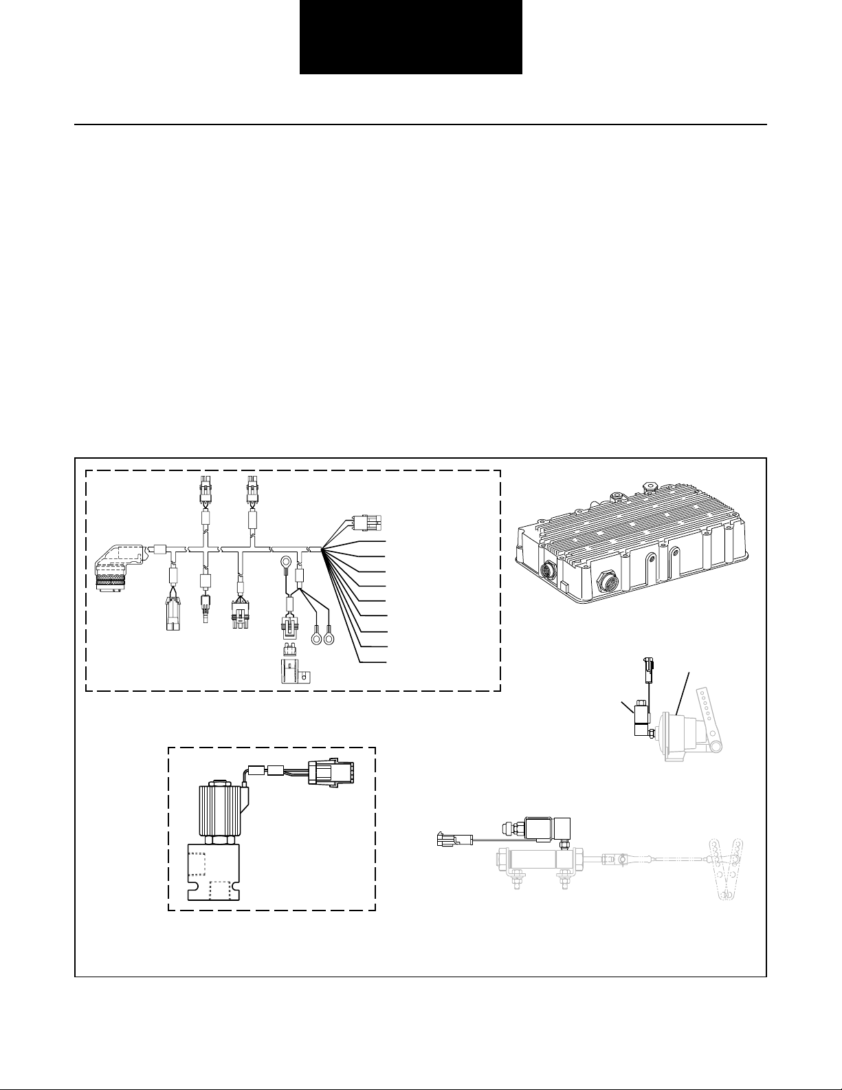
Component Code 15
Shift Lever Data Link
Fault Isolation Procedures
Fault Description
This code indicates the CEEMAT ECU did not receive an
updated shift lever status signal from the electronic shift lever
via the J-1922 data link.
Required Tools
• Basic Hand Tools
• Digital Volt/Ohm Meter
• CEEMAT Troubleshooting Guide
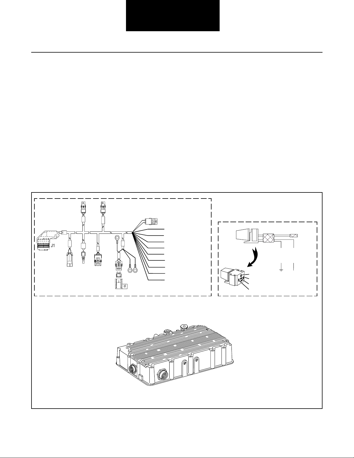
Likely Failure Locations
J1
Possible Causes
This code can be caused by any of the following conditions:
• Faulty J-1922 data link
• No electrical power to shift lever
• Faulty shift lever
• Faulty ECU
PTO
ECU
ress
P
Out
Neut
Defuel
GND
TPS
Fuse
A B
W4 ATA (+)
W3 ATA(-)
W7 Eng Brake
W15 Aux 1 Input
W16 Service Light Ground
W1B Service Light (+)
W6 Service Brake
W1C Service Brake (+)
W1 Ignition Power
W24 LAMP_GND
W25 AUX_IN
W27 AUX_OUT1
W28 AUX_OUT2
2-10
Electronic shift lever (ESL)
W1 VIGN
W2 VBAT
W13 GND
Typical shift lever harness
(OEM supplied)
Typical vehicle interface harness
(OEM supplied)
ECU
Page 26

Fault Isolation Procedures
Code 15, Shift Lever Data Link Test
Step A
OHMS
V
Step B
Procedure Condition Action
1. Select the lever to be tested
(driver or work lever).
2. Key off.
3. Disconnect connector from
electronic shift lever.
4. Disconnect positive battery cable
5. Measure resistance between
electronic shift lever harness
pin B1 and battery
negative (–) terminal.
If resistance is 0 to .3 ohms
If resistance is outside of
A
2345678 9 10 11 12
1
A
COM
B
+
–
range
A
B
Procedure Condition Action
Go to Step B.
Repair ground.
Go to Step V.
Code 15
VOLTS
V
Step C
VOLTS
V
1. Measure voltage between
electronic shift lever harness
pins A5 and B1.
If voltage is within 1 volt
of battery voltage
If voltage is outside of range
A
2345678 9 10 11 12
1
A
COM
B
A
B
Procedure Condition Action
1. Measure voltage between
electronic shift lever harness
pins A7 and B1.
A
1
B
A
COM
2345678 9 10 11 12
A
B
If voltage is 0
If voltage is not 0
Go to Step C.
Repair harness to
shift lever connector.
Go to Step V.
Go to Step D.
Repair short to power
or incorrectly wired
circuit (should be
ignition power).Go to
Step V.
2-11
Page 27

Fault Isolation Procedures
Code 15, Shift Lever Data Link Test, continued
Step D
Step E
Procedure Condition Action
1. Key on.
2. Measure voltage between
electronic shift lever harness
pins A7 and B1.
If voltage is within 1 volt
of battery voltage
VOLTS
V
COM
A
2345678 9 10 11 12
1
B
A
If voltage is outside of range
A
B
Procedure Condition Action
1. Measure resistance between
electronic shift lever harness
pins B9 and B3.
OHMS
V
A
1
B
A
COM
23 45 678 9 10 11 12
If resistance is 0 to .3 ohms
If resistance is outside of
range
A
B
Go to Step E.
Repair ignition power
line. Go to Step V.
Go to Step F.
Repair open circuit
between pins B9 and B3.
Go to Step V.
2-12
Step F
Procedure Condition Action
1. Check to see if there are
two shift levers.
One shift lever
Two shift levers
Go to Step H.
Go to Step G.
Page 28

Fault Isolation Procedures
Code 15, Shift Lever Data Link Test, continued
Step G
GROUND
Step H
Procedure Condition Action
1. Disconnect connector from
second electronic shift
lever.
2. Measure resistance between
electronic shift lever harness
pin B9 and ground.
If resistance is more than
10K ohms or infinite
OHMS
V
COM
A
2345678 9 10 11 12
1
B
A
If resistance is less than
A
10K ohms
B
Procedure Condition Action
1. Key off.
2. Disconnect J-1922 data link
from engine ECM.
3. Disconnect harness from
electronic shift lever.
4. Connect hand-held diagnostic tool.
5. Key on.
6. Select Perform Tests.
7. Select Throttle Dip Test.
8. Measure voltage between
electronic shift lever pins A9
and A10 (connect positive
lead to A10).
If voltage is +3.0 to
+4.0 volts
Go to Step H.
Both levers selected.
Repair wiring harness
to pin B9 to ensure
infinite resistance on
non-selected lever.
Go to Step V.
Go to Step I.
Code 15
A
2345678 9 10 11 12
1
B
VOLTS
A
B
V
If voltage is outside of range
A
COM
Go to Step J.
2-13
Page 29

Fault Isolation Procedures
Code 15, Shift Lever Data Link Test, continued
Step I
Step J
Procedure Condition Action
1. Activate Throttle
Dip Test.
If voltage changes to
–3.0 to –4.0 volts
If voltage does not change
to –3.0 to –4.0 volts
Procedure Condition Action
1. Disconnect vehicle interface
harness from CEEMAT.
2. Measure resistance between
vehicle interface harness
pin A and shift lever harness
pin A10.
A
23 45 678 9 10 11 12
1
B
A
OHMS
B
A
V
COM
Replace shift lever.
Go to Step V.
Go to Step J.
BAM
CPNL
DRVU
ES
F
T
GH
K
J
3. Measure resistance between
vehicle interface harness
pin P and shift lever harness
pin A9.
A
23 45 678 9 10 11 12
1
B
BAM
CPNL
DRVU
ES
F
T
GH
K
J
If resistance is 0 to .3 ohms
If resistance is outside of
A
OHMS
B
V
range
A
COM
Go to Step K.
Repair or replace
J-1922 data link
between electronic
shift lever and CEEMAT.
Go to Step V.
2-14
Page 30

Fault Isolation Procedures
Code 15, Shift Lever Data Link Test, continued
Step K
Step V
Procedure Condition Action
1.
Measure resistance between
vehicle interface harness
pins:
• A to ground
If resistance is more than
10K ohms or infinite
Replace ECU. Go
to Step V.
• P to ground
BAM
CPNL
DRVU
T
ES
GH
F
BAM
CPNL
DRVU
T
ES
GH
F
If resistance is less than
OHMS
A
V
GROUND
GROUND
COM
OHMS
V
COM
A
K
J
K
J
10K ohms
Repair or replace vehicle
interface harness. Go
to Step V.
Procedure Condition Action
Code 15
1.
Key off.
2. Reconnect all connectors.
3. Key on.
4. Clear codes (see Clearing
Fault Codes, page 1-3).
5. Use Driving Technique
to attempt to reset the code
(page 1-4).
6. Check for codes
(see Retrieving Fault Codes,
page 1-3).
If no codes
If code 15 appears
If code other than 15 appears
Test complete.
Return to Step A
to find error in testing.
Go to Fault Isolation
Procedure Index (page 1-8).
2-15
Page 31

Component Code 21
Interrupt Solenoid Coil
Fault Isolation Procedures
Fault Description
This code indicates an electrical problem in the interrupt
solenoid circuit.
Required Tools
• Basic Hand Tools
• Digital Volt/Ohm Meter
• CEEMAT Troubleshooting Guide
Likely Failed Components
ECU
Possible Causes
This code can be caused by any of the following conditions:
• Damaged torque converter harness
• Interrupt solenoid coil open or shorted
• Faulty ECU
Torque converter
harness
2-16
Page 32

Fault Isolation Procedures
Code 21, Interrupt Solenoid Coil Test
Step A
Step B
Procedure Condition Action
1. Key off.
2. Disconnect torque converter
harness from ECU.
3. Measure resistance between
torque converter harness
pins F and G.
OHMS
A
V
COM
EDC
AB
FGH
If resistance is 2.5 to 5.0 ohms
If resistance is outside of range
Go to Step B.
Replace torque
converter harness.
Go to Step V.
Procedure Condition Action
1. Measure resistance
between torque converter
harness pin F and ground.
OHMS
V
COM
GROUND
EDC
AB
FGH
A
If resistance is more than
10K ohms or infinite
If resistance is less than
10K ohms
Replace ECU. Go to
Step V.
Replace torque
converter harness.
Go to Step V.
Code 21
Step V
Procedure Condition Action
1.
Key off.
2. Reconnect all connectors.
3. Key on.
4. Clear codes (see Clearing
Fault Codes, page 1-3).
5. Use Driving Technique
to attempt to reset the code
(page 1-4).
6. Check for codes
(see Retrieving Fault Codes,
page 1-3).
If no codes
If code 21 appears
If code other than 21 appears
Test complete.
Return to Step A
to find error in testing.
Go to Fault Isolation
Procedure Index (page 1-8).
2-17
Page 33

Component Code 22
Lockup/Bypass Solenoid Coil
Fault Isolation Procedures
Fault Description
This code indicates an electrical problem in the lockup clutch
solenoid circuit.
Required Tools
• Basic Hand Tools
• Digital Volt/Ohm Meter
• CEEMAT Troubleshooting Guide
Likely Failed Components
Torque converter
ECU
Possible Causes
This code can be caused by any of the following conditions:
• Damaged torque converter harness
• Lockup/Bypass solenoid coil open or shorted
• Faulty ECU
harness
2-18
Page 34

Fault Isolation Procedures
Code 22, Lockup/Bypass Solenoid Coil Test
Step A
Step B
Procedure Condition Action
1. Key off.
2. Disconnect torque converter
harness from ECU.
3. Measure resistance between
torque converter harness
pins B and H.
EDC
AB
FGH
OHMS
V
COM
If resistance is 2.5 to 5.0 ohms
If resistance is outside of range
A
Go to Step B.
Replace torque
converter harness.
Go to Step V.
Procedure Condition Action
1. Measure resistance
between torque converter
harness pin B and ground.
EDC
AB
FGH
OHMS
V
COM
GROUND
A
If resistance is more than
10K ohms or infinite
If resistance is less than
10K ohms
Replace ECU. Go to
Step V.
Replace torque
converter harness.
Go to Step V.
Code 22
Step V
Procedure Condition Action
1.
Key off.
2. Reconnect all connectors.
3. Key on.
4. Clear codes (see Clearing
Fault Codes, page 1-3).
5. Use Driving Technique
to attempt to reset the code
(page 1-4).
6. Check for codes
(see Retrieving Fault Codes,
page 1-3).
If no codes
If code 22 appears
If code other than 22 appears
Test complete.
Return to Step A
to find error in testing.
Go to Fault Isolation
Procedure Index (page 1-8).
2-19
Page 35
Component Code 23
Engine Speed Sensor
Fault Isolation Procedures
Fault Description
This code indicates an electrical problem in the engine speed
sensor circuit. The signal from the sensor did not match the
current CEEMAT operating conditions.
Required Tools
• Hand Tools
• Digital Volt/Ohm Meter
• CEEMAT Troubleshooting Guide
Likely Failed Components
ECU
Torque converter
harness
Possible Causes
This code can be caused by any of the following conditions:
• Electrical open or short in the speed sensor circuit
• Faulty speed sensor harness or connector
• Incorrect speed sensor installation
• Incorrect configuration software
• Faulty ECU
Engine speed
sensor
Engine speed sensor
harness connector
2-20
Page 36

Fault Isolation Procedures
Code 23, Engine Speed Sensor Test
Step A
Step B
Procedure Condition Action
1. Key off.
2. Disconnect engine speed sensor
from torque converter harness.
3. Measure resistance between
engine speed sensor
pins A and B.
OHMS
A
A
V
COM
If resistance is 3K to 4K ohms
If resistance is outside of range
B
Go to Step B.
Replace engine speed
sensor. Go to Step V.
Procedure Condition Action
1. Measure resistance between
engine speed sensor
pin A and ground.
OHMS
B
A
A
V
COM
GROUND
If resistance is more
10K ohms or infinite
If resistance is less
10K ohms
than
than
Go to Step C.
Replace engine speed
sensor. Go to Step V.
Code 23
Step C
Procedure Condition Action
1. Reconnect engine speed sensor.
2. Disconnect torque converter
harness from CEEMAT.
3. Measure resistance between
torque converter harness
pins A and E.
OHMS
A
V
COM
EDC
AB
FGH
If resistance is 3K to 4K ohms
If resistance is outside of range
Go to Step D.
Repair or replace torque
converter harness as
required. Go to Step V.
2-21
Page 37

Fault Isolation Procedures
Code 23, Engine Speed Sensor Test, continued
Step D
Step V
Procedure Condition Action
1. Measure resistance between
torque converter harness
pin E and ground.
OHMS
V
COM
GROUND
A
EDC
AB
FGH
If resistance is more
10K ohms or infinite
If resistance is less
10K ohms
than
than
Replace ECU. Go to
Step V.
Repair or replace torque
converter harness as
required. Go to Step V.
Procedure Condition Action
1.
Key off.
2. Reconnect all connectors.
3. Key on.
4. Clear codes (see Clearing
Fault Codes, page 1-3).
5. Use Driving Technique
to attempt to reset the code
(page 1-4).
6. Check for codes
(see Retrieving Fault Codes,
page 1-3).
If no codes
Test complete.
2-22
If code 23 appears
If code other than 23 appears
Return to Step A
to find error in testing.
Go to Fault Isolation
Procedure Index (page 1-8).
Page 38

Fault Isolation Procedures
Code 23
This Page left blank intentionally
2-23
Page 39
Component Code 24
Hydraulic System Fault
Fault Isolation Procedures
Fault Description
This code indicates a problem in the CEEMAT hydraulic
system. The ECU detected excessive slip across the torque
converter.
Required Tools
• Basic Hand Tools
• Hand-Held Diagnostic Tool
• 0-300 PDI Hydraulic Gauges
• 0-100 PSI Hydraulic Gauge
• CEEMAT Troubleshooting Guide
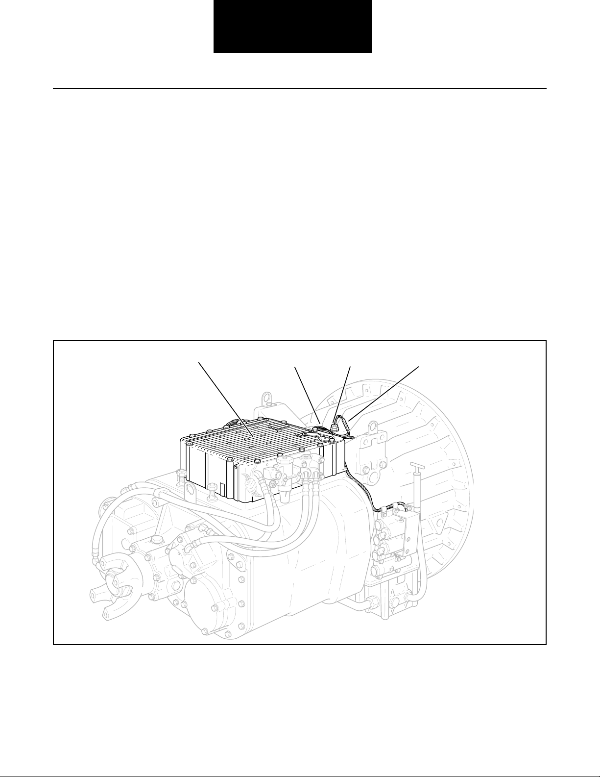
Likely Failed Component and Diagnostic Port Locations
Possible Causes
This code can be caused by any of the following conditions:
• Low fluid level
• Low fluid pressure
• Excessive slip across the converter
• Faulty interrupt or lockup clutch
• Faulty hydraulic valve
Torque
converter
2-24
Bypass
(Lockup clutch)
Interrupt clutch
Main
Lube
Page 40
Fault Isolation Procedures
Code 24 Hydraulic System Fault Test
Note: This test is identical to the basic hydraulic test.
Step A
Step B
Procedure Condition Action
1. Key on.
2. Place transmission in neutral.
3. Allow engine to idle at 600
to 700 RPM for a minimum
of 2 minutes. Ensure
transmission fluid temperature
is 60 to 120° F.
4. Check transmission fluid
level.
If fluid level is at or above
the COLD-FULL mark
If fluid level is below the
COLD-ADD mark
Go to Step B.
Correct fluid level, check
for leaks. Go to Step V.
Procedure Condition Action
1. Key off.
2. Install 0-300 PSI hydraulic
gauges into diagnostic
ports for:
• Main
• Interrupt clutch
• Lockup/ bypass clutch
3. Install a 0-100 PSI hydraulic
gauge into the lube diagnostic
port.
4. Start engine and allow air
pressure to build to governor
cutoff.
5. Turn PTO off (if equipped).
6. With engine at idle, monitor
gauges.
If pressure readings are:
• Main = 225 to 255 PSI
• Interrupt = 0 PSI of main
• Lockup/bypass = 0 PSI
• Lube = 15 to 35 PSI
Go to Step C.
Code 24
If pressure readings are
not in the ranges shown
above
Replace the hydraulic
valve. Go to Step V.
2-25
Page 41
Fault Isolation Procedures
Code 24 Hydraulic System Fault Test, continued
Step C
Step D
Procedure Condition Action
1. Connect hand-held diagnostic
tool.
2. Select Perform Tests.
3. Select Hydraulic Tests.
4. Select Interrupt Test.
5. Activate the Interrupt Test.
6. Monitor the gauges.
If pressure readings are:
• Main = 225 to 255 PSI
• Interrupt = ±5 PSI of main
• Lockup/bypass = 0 PSI
• Lube = 15 to 35 PSI
If pressure readings are
not in the ranges shown
above
Go to Step D.
Replace the hydraulic
valve. Go to Step V.
Procedure Condition Action
1. Select Lockup Test.
2. Activate the Lockup Test.
3. Monitor the gauges.
If pressure readings are:
Main = 225 to 255 PSI
Interrupt = 0 PSI
Lockup/bypass = ± 5 PSI of Main
Lube = 15 to 35 PS
Replace transmission.
Go to Step V.
2-26
Step V
If pressure readings are not
in the ranges shown above
Replace the hydraulic
valve. Go to Step V.
Verify normal operation Condition Action
1. Review or repeat
Steps C and D.
2. Test drive vehicle.
If pressure readings are
OK and vehicle operates
normally
If pressure readings are
wrong or vehicle does
not operate normally
Test complete.
Go to Step A.
Page 42

Fault Isolation Procedures
Code 24
This Page left blank intentionally
2-27
Page 43
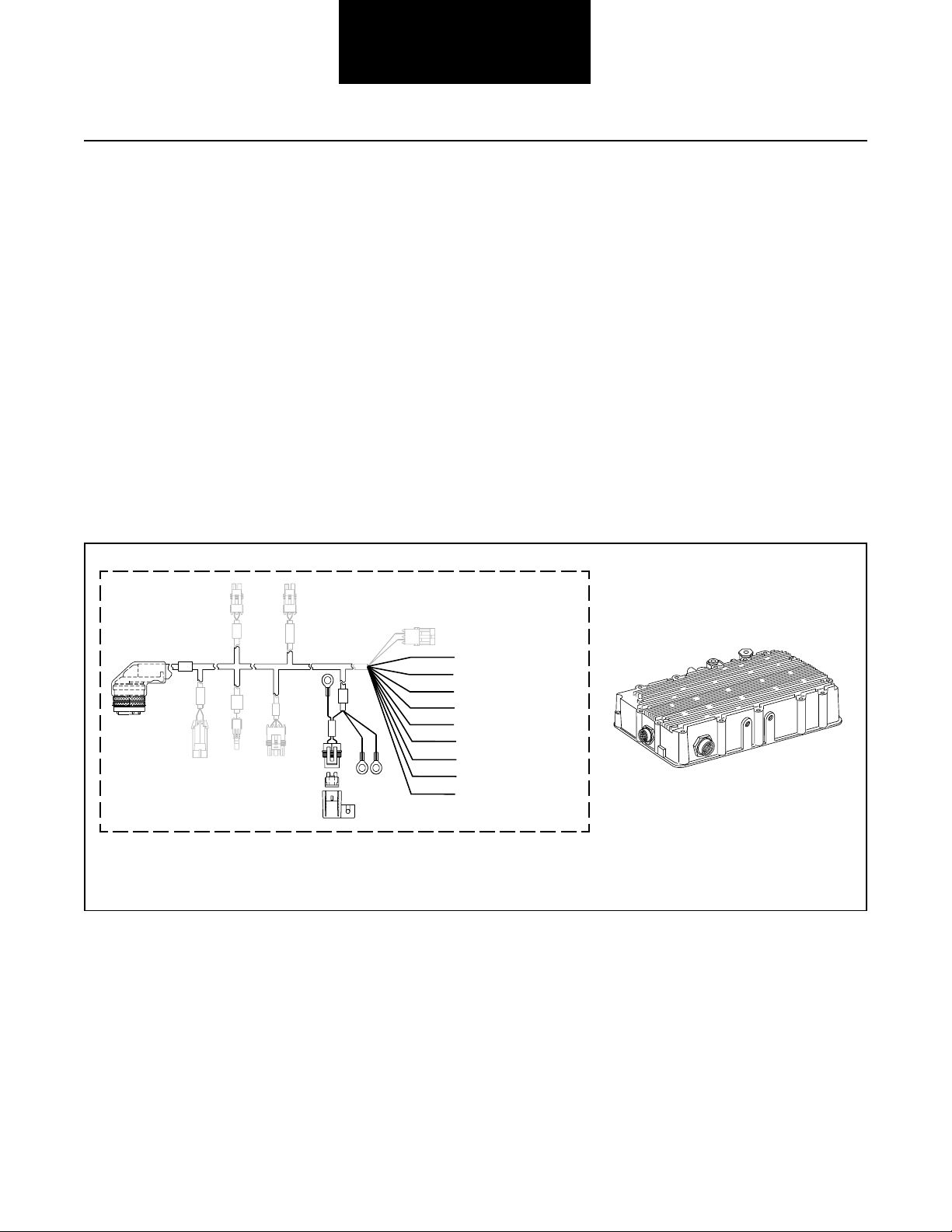
Component Code 31
Engine Brake Relay Coil
Fault Isolation Procedures
Fault Description
This code indicates an electrical problem in the engine brake
relay circuit.
Required Tools
• Basic Hand Tools
• Digital Volt/Ohm Meter
• CEEMAT Troubleshooting Guide
Likely Failed Components
PTO
ECU
s
res
J1
P
Out
Neut
Defuel
GND
TPS
Fuse
A B
Possible Causes
This code can be caused by an electrical open or short in any
of the following areas:
• Engine brake relay
• Vehicle interface harness
• Faulty ECU
W4 ATA (+)
W3 ATA(-)
W7 Eng Brake
W15 Aux 1 Input
W16 Service Light Ground
W1B Service Light (+)
W6 Service Brake
W1C Service Brake (+)
W1 Ignition Power
Pink 30
Green 86
Gray 87a
Brown 85
Green
Ground
Brown
To CEEMAT
Transmission
ECU Conn J-1
Terminal F
2-28
Typical vehicle harness
(OEM supplied)
Typical engine brake relay
(OEM supplied)
ECU
Page 44

Fault Isolation Procedures
Code 31, Engine Brake Relay Coil Test
Step A
Step B
Procedure Condition Action
1. Key off.
2. Disconnect vehicle interface
harness from transmission.
3. Measure resistance between
vehicle interface harness
pins F and B.
OHMS
A
V
COM
BAM
CPNL
DRVU
T
ES
GH
F
K
J
If resistance is 40 to 90 ohms
If resistance is outside of range
Go to Step B.
Inspect and repair or
replace vehicle interface
harness or engine brake
relay. Go to Step V.
Procedure Condition Action
1.
Measure resistance between
vehicle interface harness
pin F and ground.
BAM
OHMS
V
COM
GROUND
A
CPNL
DRVU
ES
F
T
GH
If resistance more than
10K ohms or infinite
If resistance is less
K
J
than 10K ohms
Replace ECU. Go to
Step V.
Inspect and repair or
replace vehicle interface
harness or engine brake
relay. Go to Step V.
Code 31
2-29
Page 45
Fault Isolation Procedures
Code 31, Engine Brake Relay Coil Test, continued
Step V
Procedure Condition Action
1.
Key off.
2. Reconnect all connectors.
3. Key on.
4. Clear codes (see Clearing
Fault Codes, page 1-3).
5. Use Driving Technique
to attempt to reset the code
(page 1-4).
6. Check for codes
(see Retrieving Fault Codes,
page 1-3).
If no codes
If code 31 appears
If code other than 31 appears
Test complete.
Return to Step A
to find error in testing.
Go to Fault Isolation
Procedure Index (page 1-8).
2-30
Page 46

Fault Isolation Procedures
Code 31
This Page left blank intentionally
2-31
Page 47
Component Code 32
Defuel Solenoid Coil
Fault Isolation Procedures
Fault Description
This code indicates an electrical problem in the defuel
solenoid coil circuit.
Required Tools
• Basic Hand Tools
• Digital Volt/Ohm Meter
• CEEMAT Troubleshooting Guide
Likely Failed Components
PTO
ECU
ress
J1
P
Out
Neut
Typical vehicle interface harness
Defuel
GND
TPS
Fuse
(OEM supplied)
A B
W4 ATA (+)
W3 ATA(-)
W7 Eng Brake
W15 Aux 1 Input
W16 Service Light Ground
W1B Service Light (+)
W6 Service Brake
W1C Service Brake (+)
W1 Ignition Power
Possible Causes
This code can be caused by an electrical short or open in any
of the following areas:
• Defuel solenoid coil
• Vehicle interface harness
• Faulty ECU
ECU
Throttle control
cylinder
(OEM supplied)
Kit S-2254 (12V)
S-2474 (24V)
2-32
Electro hydraulic defuel control
(OEM supplied)
Air throttle control
Electro-pneumatic
defuel control
Page 48

Fault Isolation Procedures
Code 32, Defuel Solenoid Coil Test
Step A
Step B
Procedure Condition Action
1. Key off.
2.
Disconnect vehicle interface
harness from defuel solenoid coil.
3.
Measure resistance between
coil pins.
OHMS
A
V
COM
B
A
If electro-pneumatic or air
throttle coil resistance is
13 to 18 ohms and
Electro-mechanical or air
Go to Step B.
throttle coil resistance is 2.5
to 5.0 ohms
If resistance is outside of range
Replace defuel solenoid.
Go to Step V.
Procedure Condition Action
1. Measure resistance between
defuel solenoid coil harness
terminal A and ground.
OHMS
B
A
A
V
COM
GROUND
If resistance is more than
10K ohms or infinite
If resistance is less than
10K ohms
Go to Step C.
Replace defuel solenoid.
Go to Step V.
Code 32
Step C
Procedure Condition Action
1. Reconnect defuel solenoid coil to
interface harness.
2. Disconnect vehicle interface
harness from ECU.
3. Measure resistance between
vehicle interface harness
pins H and B.
OHMS
A
V
COM
BAM
CPNL
DRVU
ES
GH
F
K
T
J
If electro-pneumatic coil
resistance is 13 to 18 ohms
and
Electro-mechanical coil
resistance is 2.5 to 5.0 ohms
If resistance is outside of range
Go to Step D.
Repair or replace vehicle
interface harness as
required. Go to Step V.
2-33
Page 49

Fault Isolation Procedures
Code 32, Defuel Solenoid Coil Test, continued
Step D
Step V
Procedure Condition Action
1. Measure resistance between
vehicle interface harness pin H
and ground.
OHMS
A
V
COM
GROUND
BAM
CPNL
DRVU
T
ES
GH
F
K
J
If resistance is more than
10K ohms or infinite
If resistance is less than
10K ohms
Replace ECU.
Go to Step V.
Repair or replace vehicle
interface harness. Go
to Step V.
Procedure Condition Action
1.
Key off.
2. Reconnect all connectors.
3. Key on.
4. Clear codes (see Clearing
Fault Codes, page 1-3).
5. Use Driving Technique
to attempt to reset the code
(page 1-4).
6. Check for codes
(see Retrieving Fault Codes,
page 1-3).
If no codes
Test complete.
If code 32 appears
If code other than 32 appears
Return to Step A
to find error in testing.
Go to Fault Isolation
Procedure Index (page 1-8).
2-34
Page 50

Fault Isolation Procedures
Code 32
This Page left blank intentionally
2-35
Page 51
Component Code 33
System Voltage
Fault Isolation Procedures
Fault Description
This code indicates low or no battery power in the vehicle
interface harness. The ECU has detected that battery power is
less than nine volts.
Required Tools
• Basic Hand Tools
• Digital Volt/Ohm Meter
• CEEMAT Troubleshooting Guide
Likely Failed Components
PTO
ECU
ress
J1
P
Out
Neut
Defuel
GND
TPS
Fuse
A B
Possible Causes
This code can be caused by any of the following conditions:
• Vehicle batteries or charging system
• Battery bus fuse circuit breaker open
• Damaged vehicle interface harness
• Faulty ECU
W4 ATA (+)
W3 ATA(-)
W7 Eng Brake
W15 Aux 1 Input
W16 Service Light Ground
W1B Service Light (+)
W6 Service Brake
W1C Service Brake (+)
W1 Ignition Power
ECU
2-36
Typical vehicle interface harness
(OEM supplied)
Page 52

Code 33, System Voltage Test
Fault Isolation Procedures
Step A
Test battery voltage Condition Action
1. Key on.
Retrieve codes (page 1-3).
2.
If code 33 is active
If code 33 is inactive
Perform Electrical Pretest
on page 2-1.
Test complete.
.
Code 33
2-37
Page 53

Component Code 34
Throttle Position Sensor
Fault Isolation Procedures
Fault Description
This code indicates an electrical problem in the throttle
position sensor circuit.
Required Tools
• Basic Hand Tools
• Digital Volt/Ohm Meter
• CEEMAT Troubleshooting Guide
Likely Failed Components
PTO
ECU
ss
re
P
J1
Neut
Defuel
Out
TPS
GND
Fuse
Possible Causes
This code can be caused by and electrical short or open in any
of the following areas:
• Throttle position sensor
• Vehicle interface harness
• Faulty ECU
A B
W4 ATA (+)
W3 ATA(-)
W7 Eng Brake
W15 Aux 1 Input
W16 Service Light Ground
W1B Service Light (+)
W6 Service Brake
W1C Service Brake (+)
W1 Ignition Power
C B A
2-38
Typical vehicle interface harness
(OEM supplied)
ECU
Linear TPS
Air throttle integral TPS
(OEM supplied)
Page 54
Fault Isolation Procedures
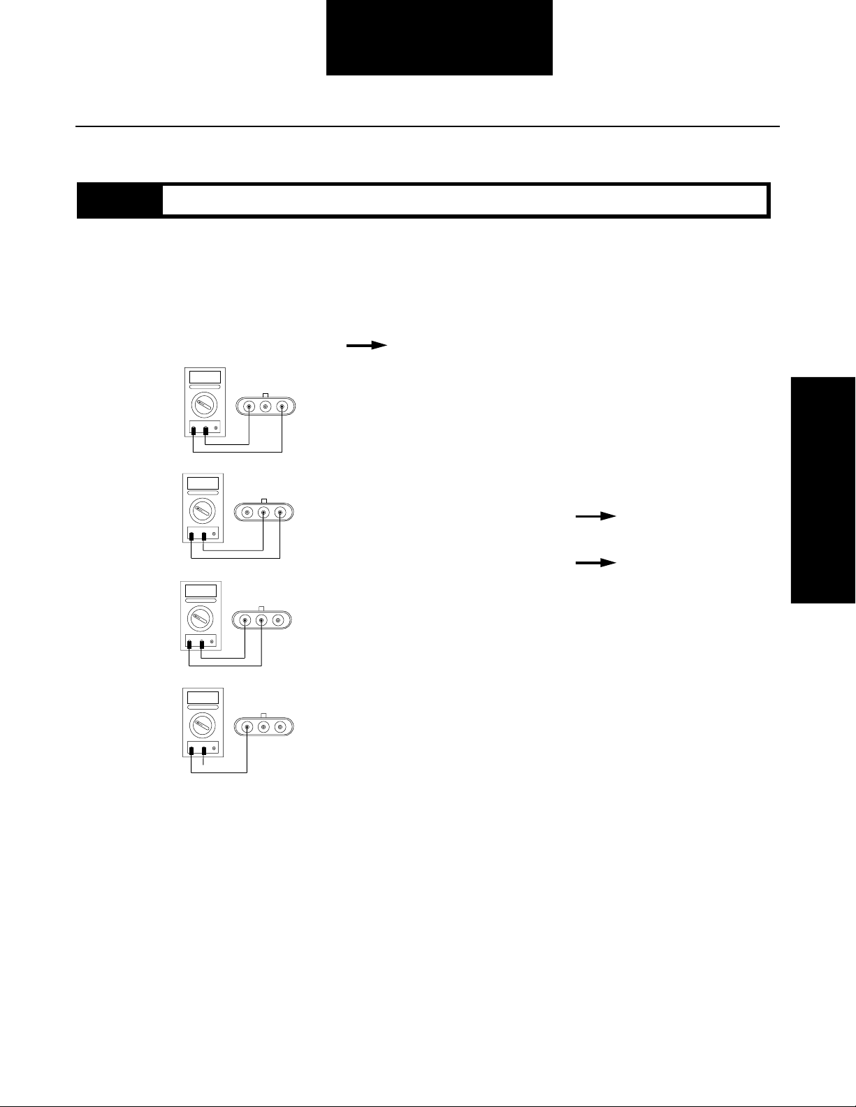
Code 34, Throttle Postition Sensor Test
Step A
Procedure Condition Action
1. Disconnect vehicle interface
harness from throttle position
sensor. Measure resistance
between sensor pins:
• A and C
• A and B while opening throttle
• B and C while opening throttle
• C and ground
OHMS
C
A
V
COM
OHMS
C
A
V
COM
OHMS
BA
C
A
V
COM
BA
BA
If A and C resistance is 2K to
15K ohms and
A and B resistance increases
smoothly while opening throttle
and
B and C resistance decreases
smoothly while opening throttle
and
C and ground resistance is
50K to infinity
If any of the above conditions
are not met
Go to Step B.
Repair or replace throttle
position sensor. Go to
Step V.
Code 34
OHMS
V
COM
GROUND
BA
C
A
2-39
Page 55

Fault Isolation Procedures
Code 34, Throttle Postition Sensor Test, continued
Step B
Procedure Condition Action
1. Reconnect throttle position
sensor.
2. Disconnect vehicle interface
harness from CEEMAT.
3. Measure resistance between
harness pins:
• J and U
• T and U
• J and T
• J and ground
OHMS
A
V
COM
OHMS
A
V
COM
BAM
CPNL
DRVU
ES
GH
F
BAM
CPNL
DRVU
T
ES
GH
F
K
T
J
K
J
If J and U resistance is 2K
to 15K ohms and
T and U resistance increases
smoothly while opening throttle
and
J and T resistance decreases
smoothly while opening throttle
and
J and ground resistance is
50K to infinity
If any of the above conditions
are not met
Replace ECU. Go to Step V.
Repair or replace vehicle
interface harness. Go to
Step V.
2-40
OHMS
V
COM
OHMS
V
COM
GROUND
BAM
CPNL
DRVU
A
A
ES
F
BAM
CPNL
DRVU
ES
F
T
GH
T
GH
K
J
K
J
Page 56

Fault Isolation Procedures
Code 34, Throttle Postition Sensor Test, continued
Step V
Procedure Condition Action
1.
Key off.
2. Reconnect all connectors.
3. Key on.
4. Clear codes (see Clearing
Fault Codes, page 1-3).
5. Use Driving Technique
to attempt to reset the code
(page 1-4).
6. Check for codes (see
Retrieving Fault Codes,
page 1-3).
If no codes
If code 34 appears
If code other than 34 appears
Test complete.
Return to Step A
to find error in testing.
Go to Fault Isolation
Procedure Index (page 1-8).
Code 34
2-41
Page 57

Fault Isolation Procedures
System Code 35
Engine Control Failure
(Mechanically-Governed Engines)
Fault Description
This code indicates the engine failed to properly respond to
throttle control during a transmission shift.
Required Tools
• Basic Hand Tools
• Hand-Held Diagnostic Tool
• CEEMAT Troubleshooting Guide
Likely Failure Locations
ECU
Possible Causes
This code can be caused by any of the following conditions:
• Low air pressure
• Contaminated air supply
• Air leak
• Engine idle adjusted too high
• Faulty defuel solenoid coil
• Throttle control system out of adjustment
• Faulty boost solenoid (air throttle only)
Throttle control
cylinder
(OEM supplied)
Kit S-2254 (12V)
S-2474 (24V)
2-42
Electro hydraulic defuel control
(OEM supplied)
Air throttle control
Electro-pneumatic
defuel control
Page 58

Fault Isolation Procedures
Code 35, Engine Control Failure Test (Mechanically-Governed Engines)
Note: Do not use this test on vehicles using electronic communication for throttle dip.
Step A
Procedure Condition Action
1. Start engine and allow to idle.
2. Connect hand-held diagnostic
tool.
3. Select Perform Tests.
4. Select Throttle Dip Test.
5. Run engine speed up to
governed RPM and activate
Throttle Dip Test.
6. Measure the time required
for the RPM to drop to
1000 RPM.
If engine RPM dropped
more than 275 RPM per
second and throttle dip
test did not abort
If engine RPM dropped
less than 275 RPM per
second
Test complete.
Inspect and adjust or
repair defuel system
as needed. If vehicle is
equipped with an
electro-pneumatic defuel
system, see Appendix for
procedure. Repeat this
step.
Code 35
2-43
Page 59

Fault Isolation Procedures
System Code 35
Engine Control Failure
(Electronically-Governed Engines)
Fault Description
This code indicates the CEEMAT failed to receive information
from the engine or the engine failed to properly respond to
throttle control during a shift as commanded by the engine
J-1922 data link.
Required Tools
• Basic Hand Tools
• Hand-Held Diagnostic Tool
• Digital Volt/Ohm Meter
• CEEMAT Troubleshooting Guide
Likely Failure Locations
PTO
ECU
ress
J1
P
Out
Neut
Defuel
GND
TPS
Fuse
A B
W4 ATA (+)
W3 ATA(-)
W7 Eng Brake
W15 Aux 1 Input
W16 Service Light Ground
W1B Service Light (+)
W6 Service Brake
W1C Service Brake (+)
W1 Ignition Power
Possible Causes
This code can be caused by any of the following conditions:
• Faulty J-1922 data link
• Faulty vehicle interface harness or connections
• Faulty engine harness or connections
• Excessive radio interference
• Faulty engine ECM
• Faulty engine fuel pump
• Faulty ECU
2-44
Typical vehicle interface harness
ECU
(OEM supplied)
DDEC III ECM Cummins ECM CAT ECM
(OEM supplied)
Page 60
Fault Isolation Procedures
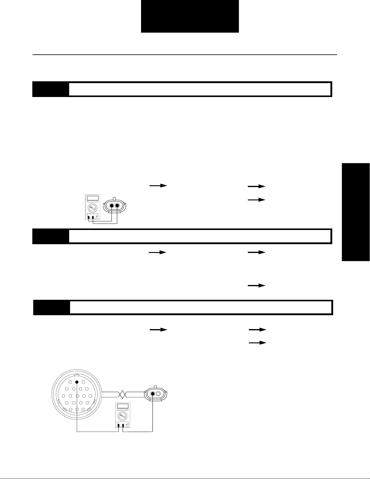
Code 35, Engine Control Failure Test (Electronically-Governed Engine)
Step A
Step B
Procedure Condition Action
1. Key on.
2. Disconnect electronic shift lever
(if equipped)
3. Disconnect J-1922 data link
(attached to vehicle interface harness).
4. Connect hand-held diagnostic tool.
5. Select Perform Tests.
6. Select Throttle Dip Test.
7. On the CEEMAT side of the data
link, measure voltage between
pins A and B (connect (+) positive
test lead to A). This connector is
typically located at the engine.
VOLTS
B
A
A
V
COM
If voltage is +3.0 to +4.0
If voltage is outside of range
Go to Step B.
Go to Step C.
Procedure Condition Action
1. Activate Throttle Dip Test.
If voltage changes to –3.0 to
–4.0 volts
CEEMAT ECU is OK.
See OEM manuals to
check engine ECM
and harness. Go to Step V.
Code 35
Step C
If voltage does not change
to –3.0 to –4.0 volts
Procedure Condition Action
1. Key off.
2. Disconnect vehicle harness
from CEEMAT.
3. Measure resistance between
vehicle interface harness
pin A and J-1922 data link pin A,
typically located at the engine.
BAM
CPNL
DRVU
ES
F
T
GH
K
J
OHMS
V
COM
A
A
If resistance is 0 to .3 ohms
If resistance is outside of
range
B
Go to Step C.
Go to Step D.
Repair or replace vehicle
interface harness.
Go to Step V.
2-45
Page 61

Fault Isolation Procedures
Code 35, Engine Control Failure Test (Electronically-Governed Engine), continued
Step D
Step E
Procedure Condition Action
1. Measure resistance between
vehicle harness interface pin P
and J-1922 data link pin B.
BAM
CPNL
DRVU
T
ES
GH
F
K
J
OHMS
V
COM
A
A
If resistance is 0 to .3 ohms
If resistance is outside of range
B
Go to Step E.
Repair or replace vehicle
interface harness.
Go to Step V.
Procedure Condition Action
1. Measure resistance between
vehicle harness interface pins:
• A to ground
• P to ground
BAM
CPNL
DRVU
ES
F
T
GH
K
J
OHMS
V
COM
GROUND
If resistance is more than
10K ohms or infinite
If resistance is less than
10K ohms
A
Replace ECU. Go to
Step V.
Repair or replace vehicle
interface harness.
Go to Step V.
2-46
BAM
CPNL
DRVU
T
ES
GH
F
OHMS
K
J
V
COM
GROUND
A
Page 62
Fault Isolation Procedures
Code 35, Engine Control Failure Test (Electronically-Governed Engine), continued
Step V
Procedure Condition Action
1.
Key off.
2. Reconnect all connectors.
3. Key on.
4. Clear codes (see Clearing
Fault Codes, page 1-3).
5. Use Driving Technique
to attempt to reset the code
(page 1-4).
6. Check for codes
(see Retrieving Fault Codes,
page 1-3).
If no codes
If code 35 appears
If code other than 35 appears
Repairs complete.
Return to Step A
to find error in testing.
Go to Fault Isolation
Procedure Index (page 1-8).
Code 35
2-47
Page 63

System Code 41
Range Failed to Engage
Fault Isolation Procedures
Fault Description
This code indicates the transmission is unable to complete a
shift across the range. The range is either stuck in HI or LO,
or cannot complete engagement in HI or LO.
Required Tools
• Basic Hand Tools
• Air Pressure Gauges (0-100 PSI)
• CEEMAT Troubleshooting Guide
• Hand-Held Diagnostic Tool
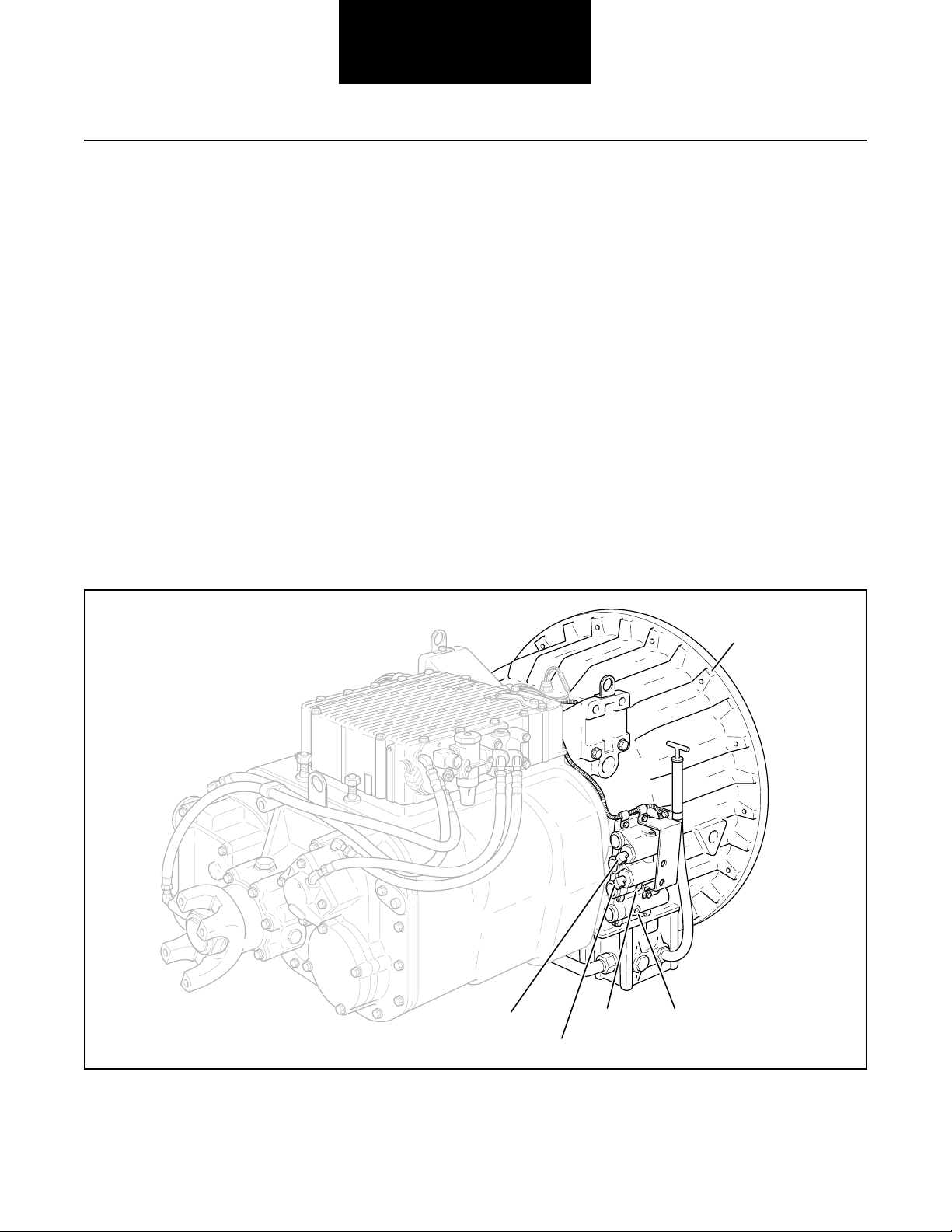
Likely Failure Locations
Synchronizer
air lines
ECU
Power
synchronizer
band line
Possible Causes
This code can be caused by any of the following conditions:
• Low air pressure
• Contaminated air supply
• Air leak
• Range solenoid stuck
• Failed range synchronizer
• Failed range actuator/cylinder/piston/yoke
• Dragging power synchronizer band
• Failed range slave valve
Range
valve
HI range
pressure air line
LO range
pressure air line
2-48
Range cylinder
Air filter/regulator
Page 64

Fault Isolation Procedures
Code 41, Range Failed to Engage Test
Step A
Procedure Condition Action
1. Install (in a “T” fashion)
0-100 PSI air gauges
into the range air lines.
2. Start vehicle and allow air
pressure to reach governor
cut-off.
3. Connect hand-held diagnostic
tool and select perform tests.
4. Select air system.
5. Select Range System Test.
6. Activate Test.
In HI range, if HI gauge is
regulated air pressure and LO
gauge is zero, and
In LO range, if LO gauge is
regulated air pressure and HI
gauge is zero
If gauges do not read as
described above
Repair auxiliary section
as required and retest.
Repair range valve on side
of ECU. If problem continues,
replace ECU and retest.
Code 41
2-49
Page 65

Component Code 43
Range Solenoid Coil
Fault Isolation Procedures
Fault Description
This code indicates an electrical problem in the range
solenoid.
Required Tools
• Basic Hand Tools
• Digital Volt/Ohm Meter
• CEEMAT Troubleshooting Guide
Likely Failed Components
Possible Causes
The code can be caused by an electrical open or short in one
of the following areas:
Cover harness
connector
• Shift bar housing cover harness
• Range solenoid coil
• Faulty ECU
Range solenoidECU
2-50
Page 66

Fault Isolation Procedures
Code 43, Range Solenoid Coil Test
Step A
Step B
Procedure Condition Action
1. Key off.
2. Remove ECU from transmission.
3. Disconnect cover harness from ECU.
4. Measure resistance between
cover harness pins 1 and 2.
OHMS
V
COM
654
A
123
If resistance is 11 to 18 ohms
If resistance is outside of range
Go to Step B.
Replace cover harness.
Go to Step V.
Procedure Condition Action
1. Measure resistance between
cover harness pin 1 and
ground.
OHMS
V
COM
GROUND
654
A
123
If resistance is more than
10K ohms or infinite
If resistance is less than
10K ohms
Replace ECU. Go to
Step V.
Replace cover harness.
Go to Step V.
Code 43
Step V
Procedure Condition Action
1.
Key off.
2. Reconnect all connectors.
3. Key on.
4. Clear codes (see Clearing
Fault Codes, page 1-3).
5. Use Driving Technique
to attempt to reset the code
(Page 1-4).
6. Check for codes
(see Retrieving Fault Codes,
page 1-3).
If no codes
If code 43 appears
If code other than 43 appears
Test complete.
Return to Step A
to find error in testing.
Go to Fault Isolation
Procedure Index (Page 1-8).
2-51
Page 67
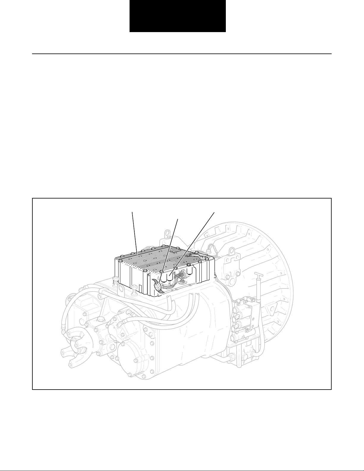
Fault Isolation Procedures
Component Code 44
Disc/Inertia Brake Solenoid Coil
Fault Description
This code indicates an electrical problem in the disk/inertia
brake.
Required Tools
• Basic Hand Tools
• Digital Volt/Ohm Meter
• CEEMAT Troubleshooting Guide
Likely Failed Components
ECU
Cover harness
Possible Causes
This code can be caused by an electrical open or short in one
of the following areas:
• Shift bar housing cover harness
• Disc/inertia brake solenoid coil
• Faulty ECU
Disc/inertia brake solenoid
connector
2-52
Page 68

Fault Isolation Procedures
Code 44, Disc/Inertia Brake Solenoid Coil Test
Step A
Step B
Procedure Condition Action
1. Key off.
2. Remove ECU from transmission.
3. Disconnect cover harness from ECU.
4. Measure resistance between
cover harness pins 5 and 6.
OHMS
V
COM
654
A
123
If resistance is 11 to 18 ohms
If resistance is outside of range
Go to Step B.
Replace cover harness.
Go to Step V.
Procedure Condition Action
1. Measure resistance between
cover harness pin 5 and
ground.
OHMS
V
COM
GROUND
654
A
123
If resistance is more than
10K ohms or infinite
If resistance is less than
10K ohms
Replace ECU. Go to
Step V.
Replace cover harness.
Go to Step V.
Code 44
Step V
Procedure Condition Action
1.
Key off.
2. Reconnect all connectors.
3. Key on.
4. Clear codes (see Clearing
Fault Codes, page 1-3).
5. Use Driving Technique
to attempt to reset the code
(page 1-4).
6. Check for codes
(see Retrieving Fault Codes,
page 1-3).
If no codes
If code 44 appears
If code other than 44 appears
Test complete.
Return to Step A
to find error in testing.
Go to Fault Isolation
Procedure Index (page 1-8).
2-53
Page 69

Fault Isolation Procedures
Component Code 45
Power Synchronizer Band/Engine
Boost Solenoid Coil
Fault Description
This code indicates an electrical problem in the band/engine
boost solenoid.
Required Tools
• Basic Hand Tools
• Digital Volt/Ohm Meter
• CEEMAT Troubleshooting Guide
Likely Failed Components
ECU
Cover harness
Possible Causes
The code can be caused by an electrical open or short in one
of the following areas:
• Shift bar housing cover harness
• Power synchronizer band/engine boost solenoid coil
• Faulty ECU
connector
Power sychronizer band/engine
boost solenoid
2-54
Page 70
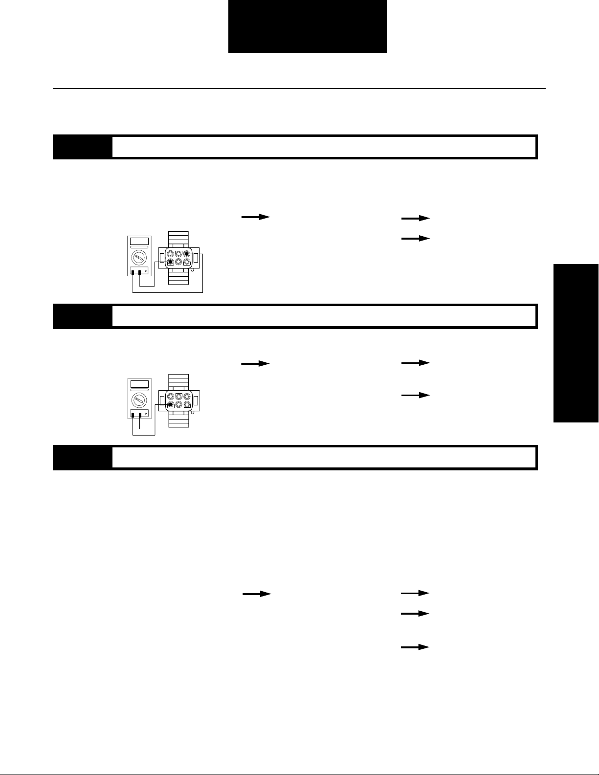
Fault Isolation Procedures
Code 45, Power Synchronizer Band/Engine Boost Solenoid Coil Test
Step A
Step B
Procedure Condition Action
1. Key off.
2. Remove ECU from transmission.
3. Disconnect cover harness from ECU.
4. Measure resistance between
cover harness pins 3 and 4.
OHMS
V
COM
654
A
123
If resistance is 11 to 18 ohms
If resistance is outside of range
Go to Step B.
Replace cover harness.
Go to Step V.
Procedure Condition Action
1. Measure resistance between
cover harness pin 3 and
ground.
OHMS
V
COM
GROUND
654
A
123
If resistance is more than
10K ohms or infinite
If resistance is less than
10K ohms
Replace ECU. Go to
Step V.
Replace cover harness.
Go to Step V.
Code 45
Step V
Procedure Condition Action
1.
Key off.
2. Reconnect all connectors.
3. Key on.
4. Clear codes (see Clearing
Fault Codes, page 1-3).
5. Use Driving Technique
to attempt to reset the code
(page 1-4).
6. Check for codes
(see Retrieving Fault Codes,
page 1-3).
If no codes
If code 45 appears
If code other than 45 appears
Test complete.
Return to Step A
to find error in testing.
Go to Fault Isolation
Procedure Index (page 1-8).
2-55
Page 71

Component Code 51
Center Rail Sensor
Fault Isolation Procedures
Fault Description
This code indicates an electrical problem in the center rail
sensor circuit.
Required Tools
• Basic Hand Tools
• Digital Volt/Ohm Meter
• CEEMAT Troubleshooting Guide
Likely Failed Components
Center rail
sensor (S1)
Possible Causes
This code can be caused by an electrical open or short in any
of the following areas:
• Center rail sensor
• Autoshifter wiring harness
• Autoshifter
• Faulty ECU
ECU
Autoshifter
harness
Autoshifter
2-56
Page 72

Code 51, Center Rear Sensor Test
Fault Isolation Procedures
Step A
Step B
Procedure Condition Action
1. Key off.
2. Remove ECU from transmission.
3. Disconnect autoshifter harness
from ECU.
4. Inspect harness and position
sensor connections for abrasions
or corrosion.
If harness and connections
Go to Step B.
are OK
If harness or connections
have poor connections,
Repair connections as
needed. Repeat this step.
abrasions or corrosion
Procedure Condition Action
1. Disconnect connector on the
gearbox center switch (S1).
2. Install a jumper wire between
the two sensor pins.
3. Measure resistance between
autoshifter harness terminals
W and D.
OHMS
A
V
COM
If resistance is 0 to .3 ohms
X
K
L
M
N
O
W
V
J
B
H
U
A
C
G
D
P
T
F
E
S
R
Q
If resistance is outside of
range
Go to Step C.
Repair or replace
autoshifter harness.
Go to Step V.
Code 51
Step C
Procedure Condition Action
1. With the jumper still
connected, measure resistance
between autoshifter harness
terminal W and ground.
X
K
L
M
N
O
W
V
J
B
H
U
A
C
G
D
P
T
F
E
S
R
Q
OHMS
V
COM
GROUND
A
If resistance is more than
10K ohms or infinite
If resistance is less than
10K ohms
Go to Step D.
Repair or replace
autoshifter harness.
Go to Step V.
2-57
Page 73
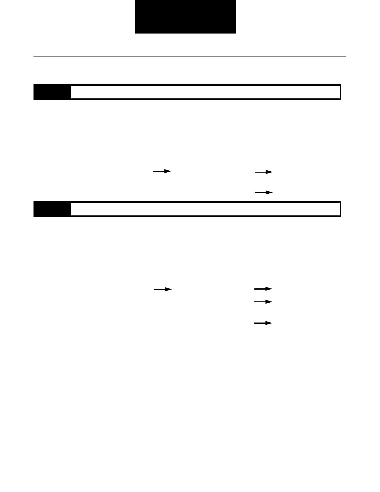
Fault Isolation Procedures
Code 51, Center Rear Sensor Test, continued
Step D
Step V
Procedure Condition Action
1. Replace the gearbox center
rail sensor (S1) and reassemble
transmission.
2. Key on.
3. Clear codes (see Clearing
Fault Codes, page 1-3).
4. Use Driving Technique to
attempt to reset the code (page 1-4).
5. Check for codes (see Retrieving
Fault Codes, page 1-3).
If code 51 appears again
If code 51 does not reappear
Replace the ECU.
Go to Step V.
Go to Step V.
Procedure Condition Action
1.
Key off.
2. Reconnect all connectors.
3. Key on.
4. Clear codes (see Clearing
Fault Codes, page 1-3).
5. Use Driving Technique
to attempt to reset the code
(page 1-4).
6. Check for codes (see Retrieving
Fault Codes, page 1-3).
If no codes
Test complete.
2-58
If code 51 appears
If code other than 51 appears
Return to Step A
to find error in testing.
Go to Fault Isolation
Procedure Index (page 1-8).
Page 74

Fault Isolation Procedures
Code 51
This Page left blank intentionally
2-59
Page 75
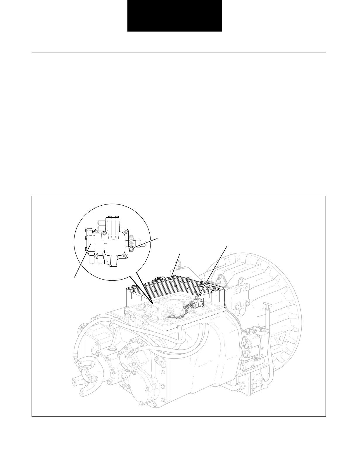
Component Code 52
Neutral Sensor
Fault Isolation Procedures
Fault Description
This code indicates an electrical problem in the neutral sensor
circuit.
Required Tools
• Basic Hand Tools
• Digital Volt/Ohm Meter
• CEEMAT Troubleshooting Guide
Likely Failed Components
Gearbox neutral
sensor (S3)
Possible Causes
This code can be caused by an electrical open or short in any
of the following areas:
• Gearbox neutral sensor
• Autoshifter wiring harness
• Autoshifter
• Faulty ECU
Autoshifter
harness
ECU
2-60
Autoshifter
Page 76

Code 52, Neutral Sensor Test
Fault Isolation Procedures
Step A
Step B
Procedure Condition Action
1. Key off.
2. Remove ECU from transmission.
3. Disconnect autoshifter harness
from ECU.
4. Inspect harness and position
sensor connections for abrasions
or corrosion.
If harness and connections
Go to Step B.
are OK
If harness or connections
have poor connections,
Repair connections as
needed. Repeat this step.
abrasions or corrosion
Procedure Condition Action
1. Disconnect connector on the
gearbox neutral switch (S3).
2. Install a jumper wire between
the two sensor pins.
3. Measure resistance between
autoshifter harness terminals
J and L.
X
K
OHMS
V
COM
L
M
N
A
O
W
V
J
B
H
U
A
C
G
D
P
T
F
E
S
R
Q
If resistance is 0 to .3 ohms
If resistance is outside of
range
Go to Step C.
Repair or replace
autoshifter harness.
Go to Step V.
Code 52
2-61
Page 77

Fault Isolation Procedures
Code 52, Neutral Sensor Test, continued
Step C
Step D
Procedure Condition Action
1. With the jumper still connected,
measure resistance between
autoshifter harness terminal J
and ground.
OHMS
A
V
COM
GROUND
X
K
L
M
N
O
W
V
J
B
H
U
A
C
G
D
P
T
F
E
S
R
Q
If resistance is more than
10K ohms or infinite
If resistance is less than
10K ohms
Go to Step D.
Repair or replace
autoshifter harness.
Go to Step V.
Procedure Condition Action
1. Replace the gearbox center
rail sensor (S1) and reassemble
transmission.
2. Key on.
3. Clear codes (see Clearing
Fault Codes, page 1-3).
4. Use Driving Technique to
attempt to reset the code (page 1-4).
5. Check for codes (see Retrieving
Fault Codes, page 1-3).
If code 52 appears again
Replace the ECU.
Go to Step V.
2-62
Step V
If code 52 does not reappear
Go to Step V.
Procedure Condition Action
1.
Key off.
2. Reconnect all connectors.
3. Key on.
4. Clear codes (see Clearing
Fault Codes, page 1-3).
5. Use Driving Technique
to attempt to reset the code
(Page 1-4).
6. Check for codes
(see Retrieving Fault Codes,
page 1-3).
If no codes
If code 52 appears
If code other than 52 appears
Test complete.
Return to Step A
to find error in testing.
Go to Fault Isolation
Procedure Index (page 1-8).
Page 78

Fault Isolation Procedures
Code 52
This Page left blank intentionally
2-63
Page 79

Component Code 53
Gear Engaged Sensor
Fault Isolation Procedures
Fault Description
This code indicates an electrical problem in the gear engaged
sensor circuit.
Required Tools
• Basic Hand Tools
• Digital Volt/Ohm Meter
• CEEMAT Troubleshooting Guide
Likely Failed Components
Gearbox engaged
sensor (bottom)
Possible Causes
This code can be caused by an electrical open or short in any
of the following areas:
• Gearbox engaged sensor
• Autoshifter wiring harness
• Autoshifter
• Faulty ECU
(S2)
ECU
Autoshifter
harness
2-64
Autoshifter
Page 80

Fault Isolation Procedures
Code 53, Gear Engaged Sensor Test
Step A
Step B
Procedure Condition Action
1. Key off.
2. Remove ECU from transmission.
3. Disconnect autoshifter harness
from ECU.
4. Inspect harness and position
sensor connections for abrasions
or corrosion.
If harness and connections
Go to Step B.
are OK
If harness or connections
have poor connections,
Repair connections as
needed. Repeat this step.
abrasions or corrosion
Procedure Condition Action
1. Disconnect connector on the
gearbox engaged switch (S2).
2. Install a jumper wire between
the two sensor pins.
3. Measure resistance between
autoshifter harness terminals
K and H.
OHMS
A
V
COM
If resistance is 0 to .3 ohms
X
K
W
L
B
M
C
N
D
O
P
V
J
H
U
A
G
T
F
E
S
R
Q
If resistance is outside of
range
Go to Step C.
Repair or replace
autoshifter harness.
Go to Step V.
Code 53
Step C
Procedure Condition Action
1. With the jumper still
connected, measure resistance
between autoshifter harness
terminal K and ground.
X
K
W
OHMS
V
COM
GROUND
L
B
M
C
N
A
D
O
P
V
J
H
U
A
G
T
F
E
S
R
Q
If resistance is more than
10K ohms or infinite
If resistance is less than
10K ohms
Go to Step D.
Repair or replace
autoshifter harness. Go
to Step V.
2-65
Page 81
Fault Isolation Procedures
Code 53, Gear Engaged Sensor Test, continued
Step D
Step V
Procedure Condition Action
1. Replace the gearbox engaged
switch (S2) and reassemble
transmission.
2. Key on.
3. Clear codes (see Clearing
Fault Codes, page 1-3).
4. Use Driving Technique to attempt
to reset the code (page 1-4).
5. Check for codes (see Retrieving
Fault Codes, page 1-3).
If code 53 appears again
If code 53 does not reappear
Replace the ECU.
Go to Step V.
Go to Step V.
Procedure Condition Action
1.
Key off.
2. Reconnect all connectors.
3. Key on.
4. Clear codes (see Clearing
Fault Codes, page 1-3).
5. Use Driving Technique
to attempt to reset the code
(page 1-4).
6. Check for codes (see Retrieving
Fault Codes, page 1-3).
If no codes
Test complete.
2-66
If code 53 appears
If code other than 53 appears
Return to Step A
to find error in testing.
Go to Fault Isolation
Procedure Index (page 1-8).
Page 82

Fault Isolation Procedures
Code 53
This Page left blank intentionally
2-67
Page 83

Component Code 54
HI Range Sensor
Fault Isolation Procedures
Fault Description
This code indicates an electrical problem in the
HI range sensor circuit.
Required Tools
• Basic Hand Tools
• Digital Volt/Ohm Meter
• CEEMAT Troubleshooting Guide
Likely Failed Components
Shift bar housing
ECU
Autoshifter harness
Possible Causes
This code can be caused by an electrical open or short in any
of the following areas:
• HI range sensor
• Autoshifter wiring harness
• Range switch actuator shaft/pins
• Faulty ECU
HI range
sensor
2-68
Page 84

Code 54, HI Range Sensor Test
Fault Isolation Procedures
Step A
Step B
Procedure Condition Action
1. Key off.
2. Remove ECU from transmission.
3. Disconnect autoshifter harness
from ECU.
4. Inspect harness and position
sensor connections for abrasions
or corrosion.
If harness and connections
Go to Step B.
are OK
If harness or connections
have poor connections,
Repair connections as
needed. Go to Step A.
abrasions or corrosion
Procedure Condition Action
1. Disconnect connector on the
HI range switch (S4).
2. Install a jumper wire between
the two sensor pins.
3. Measure resistance between
autoshifter harness terminals
B and U.
X
K
OHMS
V
COM
L
M
N
A
O
W
V
J
B
H
U
A
C
G
D
P
T
F
E
S
R
Q
If resistance is 0 to .3 ohms
If resistance is outside of
range
Go to Step C.
Repair or replace
autoshifter harness.
Go to Step V.
Code 54
Step C
Procedure Condition Action
1. With the jumper still connected,
measure resistance between
autoshifter harness terminal
B and ground. If resistance is more than
10K ohms or infinite
X
K
W
V
J
B
H
U
A
C
G
D
P
T
F
E
S
R
Q
If resistance is less than
10K ohms
GROUND
OHMS
V
COM
L
M
N
A
O
Go to Step D.
Repair or replace
autoshifter harness.
Go to Step V.
2-69
Page 85

Fault Isolation Procedures
Code 54, HI Range Sensor Test, continued
Step D
Step V
Procedure Condition Action
1. Replace the gearbox center
rail sensor (S1) and reassemble
transmission.
2. Key on.
3. Clear codes (see Clearing
Fault Codes, page 1-3).
4. Use Driving Technique to
attempt to reset the code (page 1-4).
5. Check for codes (see Retrieving
Fault Codes, page 1-3).
If code 54 appears again
If code 54 does not reappear
Replace the ECU.
Go to Step V.
Go to Step V.
Procedure Condition Action
1.
Key off.
2. Reconnect all connectors.
3. Key on.
4. Clear codes (see Clearing
Fault Codes, page 1-3).
5. Use Driving Technique
to attempt to reset the code
(page 1-4).
6. Check for codes
(see Retrieving Fault Codes,
page 1-3).
If no codes
Test complete.
2-70
If code 54 appears
If code other than 54 appears
Return to Step A
to find error in testing.
Go to Fault Isolation
Procedure Index (page 1-8).
Page 86

Fault Isolation Procedures
Code 54
This Page left blank intentionally
2-71
Page 87

Component Code 55
LO Range Sensor
Fault Isolation Procedures
Fault Description
This code indicates an electrical problem in the LO range
sensor circuit.
Required Tools
• Basic Hand Tools
• Digital Volt/Ohm Meter
• CEEMAT Troubleshooting Guide
Likely Failed Components
Shift bar housing
ECU
Possible Causes
This code can be caused by an electrical open or short in any
of the following areas:
• LO range sensor
• Autoshifter wiring harness
• Range switch actuator shaft /pins
• Faulty ECU
LO range
sensor
Autoshifter harness
2-72
Page 88
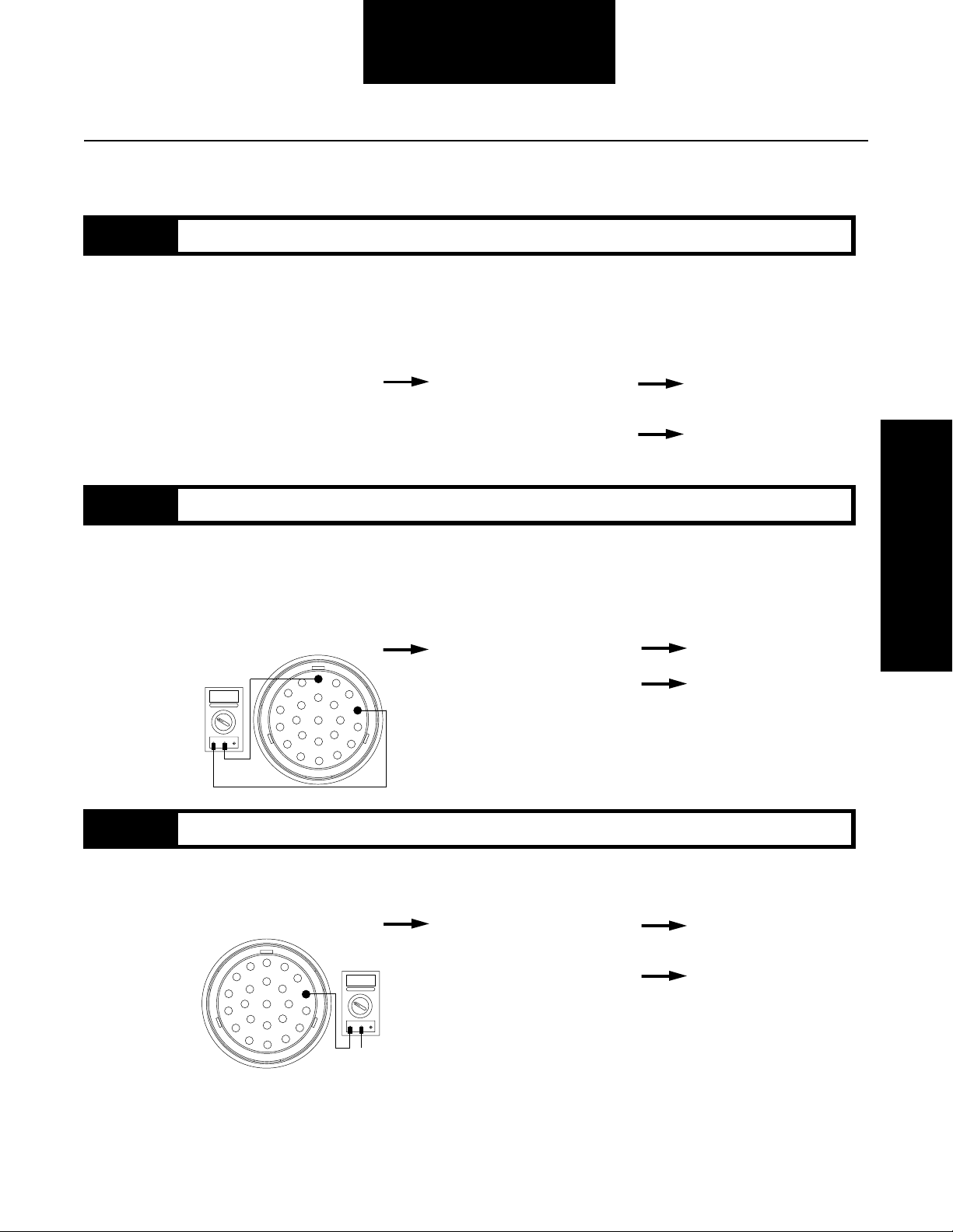
Code 55, LO Range Sensor Test
Fault Isolation Procedures
Step A
Step B
Procedure Condition Action
1. Key off.
2. Remove ECU from transmission.
3. Disconnect autoshifter harness
from ECU.
4. Inspect harness and position
sensor connections for abrasions
or corrosion.
If harness and connections
Go to Step B.
are OK
If harness and connections
have poor connections,
Repair connections as
needed. Go to Step A.
abrasions or corrosion
Procedure Condition Action
1. Disconnect connector on the
LO range switch (S5).
2. Install a jumper wire between
the two sensor pins.
3. Measure resistance between
autoshifter harness terminals
U and X.
X
K
W
OHMS
V
COM
L
B
M
C
N
A
D
O
P
V
J
H
U
A
G
T
F
E
S
R
Q
If resistance is 0 to .3 ohms
If resistance is outside of
range
Go to Step C.
Repair or replace
autoshifter harness.
Go to Step V.
Code 55
Step C
Procedure Condition Action
1. With the jumper still connected,
measure resistance between
autoshifter harness terminal U
and ground.
X
K
L
J
B
M
A
C
N
D
E
O
P
Q
W
V
H
U
G
T
F
S
R
OHMS
V
COM
GROUND
A
If resistance is more than
10K ohms or infinite
If resistance is less than
10K ohms
Go to Step D.
Repair or replace
autoshifter harness.
Go to Step V.
2-73
Page 89
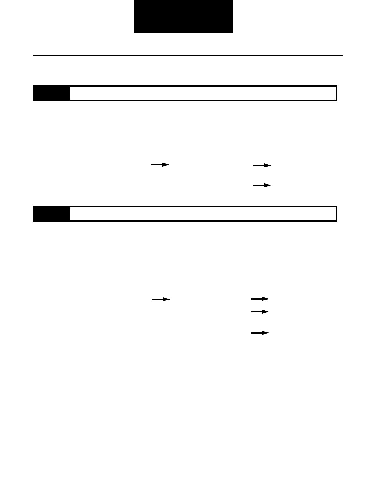
Fault Isolation Procedures
Code 55, LO Range Sensor Test, continued
Step D
Step V
Procedure Condition Action
1. Replace the LO range switch (S5)
and reassemble transmission.
2. Key on.
3. Clear codes (see Clearing Fault
Codes, page 1-3).
4. Use Driving Technique to attempt
to reset the code (page 1-4).
5.Check for codes (see Retrieving
Fault Codes, page 1-3).
If code 55 appears again
If code 55 does not reappear
Replace the ECU.
Go to Step V.
Go to Step V.
Procedure Condition Action
1.
Key off.
2. Reconnect all connectors.
3. Key on.
4. Clear codes (see Clearing
Fault Codes, page 1-3).
5. Use Driving Technique
to attempt to reset the code
(page 1-4).
6. Check for codes
(see Retrieving Fault Codes,
page 1-3).
If no codes
Test complete.
2-74
If code 55 appears
If code other than 55 appears
Return to Step A
to find error in testing.
Go to Fault Isolation
Procedure Index (page 1-8).
Page 90

Fault Isolation Procedures
Code 55
This Page left blank intentionally
2-75
Page 91

Component Code 56
Input Speed Sensor
Fault Isolation Procedures
Fault Description
This code indicates an electrical problem in the input shaft
speed sensor circuit. The signal from the sensor did not
match the current CEEMAT operating conditions.
Required Tools
• Basic Hand Tools
• Digital Volt/Ohm Meter
• CEEMAT Troubleshooting Guide
Likely Failed Components
Autoshifter harness
ECU
Possible Causes
This code can be caused by any of the following conditions:
• Poor vehicle electrical ground
• Improper input speed sensor installation
• Defective input speed sensor
• Defective countershaft gear
• Electrical open or short in the autoshifter harness
• Incorrect configuration software
• Faulty ECU
Input speed
sensor
2-76
Page 92
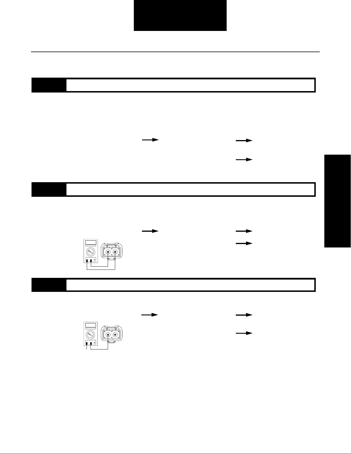
Fault Isolation Procedures
Code 56, Input Speed Sensor Test
Step A
Step B
Procedure Condition Action
1. Key off.
2. Remove ECU from transmission.
3. Disconnect autoshifter harness
from ECU.
4. Inspect harness and input
speed sensor connections for
abrasions or corrosion.
If harness and connections
Go to Step B.
are OK
If harness and connections
have poor connections,
Repair connections as
needed. Go to Step A.
abrasions or corrosion
Procedure Condition Action
1. Disconnect input speed
sensor from autoshifter harness.
2. Measure resistance of input
speed sensor between pins
A and B.
OHMS
V
If resistance is 3K to 4K ohms
If resistance is outside of range
B
A
A
COM
Go to Step C.
Replace input speed
sensor. Go to Step V.
Code 56
Step C
Procedure Condition Action
1. Measure resistance of input speed
sensor between pin A and
ground.
OHMS
V
GROUND
If resistance is more
than
10K ohms or infinite
B
A
A
COM
If resistance is less
10K ohms
than
Go to Step D.
Replace input speed
sensor. Go to Step V.
2-77
Page 93

Fault Isolation Procedures
Code 56, Input Speed Sensor Test, continued
Step D
Step E
Procedure Condition Action
1.
Reconnect speed sensor to
autoshifter harness.
2. Disconnect autoshifter harness
from ECU.
3. Measure resistance between
autoshifter harness pins
M and C.
OHMS
A
V
COM
X
K
W
L
B
M
C
N
D
O
P
V
J
H
U
A
G
T
F
E
S
R
Q
If resistance is 3K to 4K ohms
If resistance is outside of range
Go to Step E.
Repair or replace autoshifter
harness as required.
Go to Step V.
Procedure Condition Action
1. Measure resistance between
autoshifter harness pin M and
ground.
OHMS
A
V
COM
GROUND
X
K
L
M
N
O
W
V
J
B
H
U
A
C
G
D
P
T
F
E
S
R
Q
If resistance is more than
10K ohms or infinite
If resistance is less than
10K ohms
Replace ECU. Go to Step V.
Repair or replace autoshifter
harness as required.
Go to Step V.
2-78
Step V
Procedure Condition Action
1.
Key off.
2. Reconnect all connectors.
3. Key on.
4. Clear codes (see Clearing
Fault Codes, page 1-3).
5. Use Driving Technique
to attempt to reset the code
(page 1-4).
6. Check for codes
(see Retrieving Fault Codes,
page 1-3).
If no codes
If code 56 appears
If code other than 56
Test complete.
Return to Step A
to find error in testing.
Go to Fault Isolation
Procedure Index (page 1-8).
Page 94

Fault Isolation Procedures
Code 56
This Page left blank intentionally
2-79
Page 95

Component Code 57
Output Speed Sensor
Fault Isolation Procedures
Fault Description
This code indicates an electrical problem in the output shaft
speed sensor circuit. The signal from the sensor did not
match the current CEEMAT operating conditions.
Required Tools
• Basic Hand Tools
• Digital Volt/Ohm Meter
• CEEMAT Troubleshooting Guide
Likely Failed Components
Autoshifter harness
Output speed
sensor
ECU
Possible Causes
This code can be caused by any of the following conditions:
• Poor vehicle electrical ground
• Improper output speed sensor installation
• Defective output speed sensor
• Defective auxiliary countershaft gear
• Electrical open or short in the autoshifter harness
• Incorrect configuration software
• Faulty ECU
2-80
Page 96

Fault Isolation Procedures
Code 57, Output Speed Sensor Test
Step A
Step B
Procedure Condition Action
1. Key off.
2. Remove ECU from transmission.
3. Disconnect autoshifter harness
from ECU.
4. Inspect harness and output
speed sensor connections for
abrasions or corrosion.
If harness and connections
Go to Step B.
are OK
If harness and connections
have poor connections,
Repair connections as
needed. Go to Step A.
abrasions or corrosion
Procedure Condition Action
1. Disconnect output speed
sensor from autoshifter harness.
2. Measure resistance of output
speed sensor between pins
A and B.
OHMS
V
If resistance is 3K to 4K ohms
If resistance is outside of range
B
A
A
COM
Go to Step C.
Replace input speed
sensor. Go to Step V.
Code 57
Step C
Procedure Condition Action
1. Measure resistance of output speed
sensor between pin A and
ground.
OHMS
V
GROUND
If resistance is more
than
10K ohms or infinite
B
A
A
COM
If resistance is less
10K ohms
than
Go to Step D.
Replace output speed
sensor. Go to Step V.
2-81
Page 97
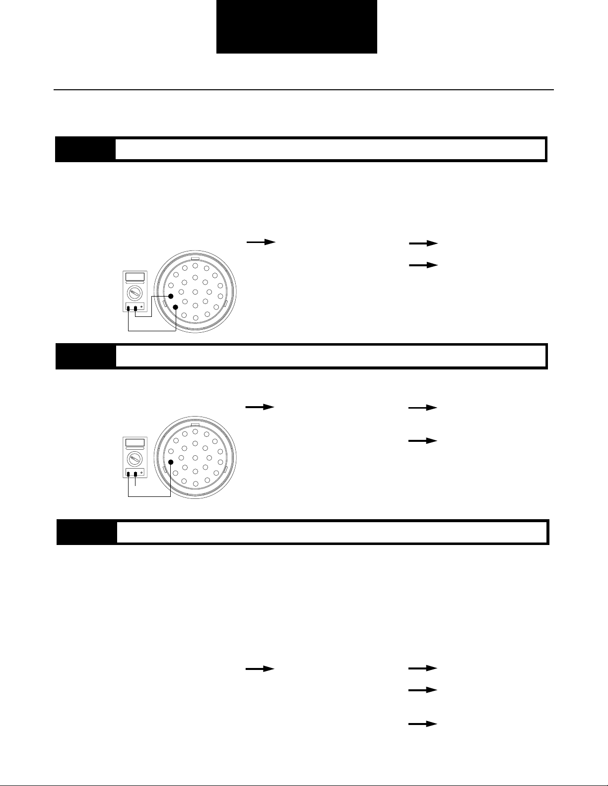
Fault Isolation Procedures
Code 57, Output Speed Sensor Test, continued
Step D
Step E
Procedure Condition Action
1.
Reconnect speed sensor to
autoshifter harness.
2. Disconnect autoshifter harness
from CEEMAT.
3. Measure resistance between
autoshifter harness pins
N and O.
OHMS
A
V
COM
X
K
L
M
N
O
W
V
J
B
H
U
A
C
G
D
P
T
F
E
S
R
Q
If resistance is 3K to 4K ohms
If resistance is outside of range
Go to Step E.
Repair or replace autoshifter
harness as required.
Go to Step V.
Procedure Condition Action
1. Measure resistance between
autoshifter harness pin N and
ground.
OHMS
A
V
COM
GROUND
X
K
L
M
N
O
W
V
J
B
H
U
A
C
G
D
P
T
F
E
S
R
Q
If resistance is more than
10K ohms or infinite
If resistance is less than
10K ohms
Replace ECU. Go to Step V.
Repair or replace autoshifter
harness as required.
Go to Step V.
2-82
Step V
Procedure Condition Action
1.
Key off.
2. Reconnect all connectors.
3. Key on.
4. Clear codes (see Clearing
Fault Codes, page 1-3).
5. Use Driving Technique
to attempt to reset the code
(page 1-4).
6. Check for codes
(see Retrieving Fault Codes,
page 1-3).
If no codes
If code 57 appears
If code other than 57
Test complete.
Return to Step A
to find error in testing.
Go to Fault Isolation
Procedure Index (page 1-8).
Page 98

Fault Isolation Procedures
Code 57
This Page left blank intentionally
2-83
Page 99
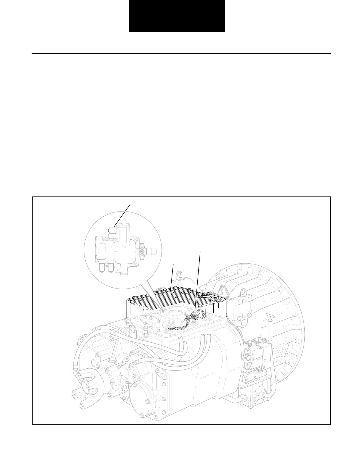
Component Code 61
Autoshifter Solenoid 1 Coil
Fault Isolation Procedures
Fault Description
This code indicates an electrical problem in the autoshifter
solenoid 1 coil circuit.
Required Tools
• Basic Hand Tools
• Digital Volt/Ohm Meter
• CEEMAT Troubleshooting Guide
Likely Failed Components
Solenoid 1 (P1)
Possible Causes
This code can be caused by an electrical open or short in any
of the following areas:
• Autoshifter wiring harness
• Solenoid coil
• Faulty ECU
Autoshifter harness
ECU
2-84
Page 100

Fault Isolation Procedures
Code 61, Autoshifter Solenoid 1 Coil Test
Step A
Step B
Procedure Condition Action
1. Key off.
2. Remove ECU from transmission.
3. Disconnect autoshifter harness
from ECU.
4. Measure resistance between
autoshifter harness pins T
and F.
OHMS
V
COM
If resistance is 11 to 18 ohms
X
K
L
M
N
A
O
W
V
J
B
H
U
A
C
G
D
P
T
F
E
S
R
Q
If resistance is outside
of range
Go to Step B.
Replace autoshifter
harness and retest.
Go to Step V.
Procedure Condition Action
1. Measure resistance between
autoshifter harness pin T
and ground.
OHMS
A
V
COM
GROUND
If resistance is more than
X
K
L
M
N
O
W
V
J
B
H
U
A
C
G
D
P
T
F
E
S
R
Q
10K ohms or infinite
If resistance is less than
10K ohms
Replace the ECU.
Go to Step V.
Replace autoshifter
harness. Go to Step V.
Code 61
Step V
Procedure Condition Action
1.
Key off.
2. Reconnect all connectors.
3. Key on.
4. Clear codes (see Clearing
Fault Codes, page 1-3).
5. Use Driving Technique
to attempt to reset the code
(page 1-4).
6. Check for codes
(see Retrieving Fault Codes,
page 1-3).
If no codes
If code 61 appears
If code other than 61 appears
Test complete.
Return to Step A
to find error in testing.
Go to Fault Isolation
Procedure Index (page 1-8).
2-85
 Loading...