


Medical Air Compressor

Emergency Care · OR/Anesthesia · Critical Care · Perinatal Care · Home Care
Because you care
Atemluftkompressor
Gebrauchsanweisung, Seite 2
Medical Air Compressor
Instructions for Use, Page 2
Compresseur d'air médical
Notice d'utilisation, Page 26
Compresor de aire
Instrucciones de uso, Página 26
Ademluchtcompressor
Gebruiksaanwijzing, Página 50
Compressore di aria respiratoria
Istruzioni per l'uso, Página 50
Andningsluftkompressor
Bruksanvisning, Sida 74
Компрессор дыхательного
воздуха
Руководство по эксплуатации,
стр.74
Kompresor powietrza
medycznego
Instrukcja obsługi, strona 98
Compressor de ar respiratório
Manual de instruções, Página 98
呼吸气体空压机
使用说明书 , 页 122
医療用空気圧縮機
取扱説明書 , 122 ページ
Medikal Hava Kompresörü
Kullanma Kılavuzu, Sayfa 146

Inhaltsverzeichnis
2
Contents
Inhaltsverzeichnis
Zu Ihrer und Ihrer Patienten Sicherheit . . . . . . . . . . . . . . . . . 3
Hinweise zum sicheren Gebrauch . . . . . . . . . . . . . . . . . . . . . . 4
Zweckbestimmung . . . . . . . . . . . . . . . . . . . . . . . . . . . . . . . . . . 5
Vorbereiten . . . . . . . . . . . . . . . . . . . . . . . . . . . . . . . . . . . . . . . . . 5
Vor der ersten Inbetriebnahme . . . . . . . . . . . . . . . . . . . . . . . . . 5
Auf das Evita Mobil-Fahrgestell montieren . . . . . . . . . . . . . . . . 6
Auf den separaten Fahrgestellfuß montieren . . . . . . . . . . . . . 9
Kompressor anschließen . . . . . . . . . . . . . . . . . . . . . . . . . . . . . . 9
Für Standby-Funktion . . . . . . . . . . . . . . . . . . . . . . . . . . . . . . . 10
Betrieb . . . . . . . . . . . . . . . . . . . . . . . . . . . . . . . . . . . . . . . . . . . . 11
Standby-Funktion . . . . . . . . . . . . . . . . . . . . . . . . . . . . . . . . . . . 11
Betriebsende . . . . . . . . . . . . . . . . . . . . . . . . . . . . . . . . . . . . . . 11
Pflege . . . . . . . . . . . . . . . . . . . . . . . . . . . . . . . . . . . . . . . . . . . . . 12
Instandhaltungsintervalle . . . . . . . . . . . . . . . . . . . . . . . . . . . . 13
Filtergruppe ausbauen . . . . . . . . . . . . . . . . . . . . . . . . . . . . . . 13
Vorfilter wechseln . . . . . . . . . . . . . . . . . . . . . . . . . . . . . . . . . . 14
Hauptfilter wechseln . . . . . . . . . . . . . . . . . . . . . . . . . . . . . . . . 14
Ansaugfilter wechseln . . . . . . . . . . . . . . . . . . . . . . . . . . . . . . . 16
Filtergruppe einbauen . . . . . . . . . . . . . . . . . . . . . . . . . . . . . . . 17
Sicherungen wechseln . . . . . . . . . . . . . . . . . . . . . . . . . . . . . . 17
Fehler - Ursache - Abhilfe . . . . . . . . . . . . . . . . . . . . . . . . . . . . 18
Was ist was . . . . . . . . . . . . . . . . . . . . . . . . . . . . . . . . . . . . . . . 20
Technische Daten . . . . . . . . . . . . . . . . . . . . . . . . . . . . . . . . . . 21
Funktionsbeschreibung . . . . . . . . . . . . . . . . . . . . . . . . . . . . 23
Bestell-Liste . . . . . . . . . . . . . . . . . . . . . . . . . . . . . . . . . . . . . . . 25
Contents
For Your Safety and that of your Patients . . . . . . . . . . . . . . . 3
Safety instructions . . . . . . . . . . . . . . . . . . . . . . . . . . . . . . . . . . . . 4
Intended Use . . . . . . . . . . . . . . . . . . . . . . . . . . . . . . . . . . . . . . . . 5
Preparing for use . . . . . . . . . . . . . . . . . . . . . . . . . . . . . . . . . . . . 5
Before first use . . . . . . . . . . . . . . . . . . . . . . . . . . . . . . . . . . . . . . . 5
Installing the compressor on the Evita trolley . . . . . . . . . . . . . 6
Installing the compressor on a seperate trolley . . . . . . . . . . . . 9
Connecting the compressor . . . . . . . . . . . . . . . . . . . . . . . . . . . . 9
Standby mode . . . . . . . . . . . . . . . . . . . . . . . . . . . . . . . . . . . . . 10
Operation . . . . . . . . . . . . . . . . . . . . . . . . . . . . . . . . . . . . . . . . . . 11
Standby mode . . . . . . . . . . . . . . . . . . . . . . . . . . . . . . . . . . . . . 11
Switching off . . . . . . . . . . . . . . . . . . . . . . . . . . . . . . . . . . . . . . . 11
Routine maintenance . . . . . . . . . . . . . . . . . . . . . . . . . . . . . . . 12
Maintenance intervals . . . . . . . . . . . . . . . . . . . . . . . . . . . . . . . 13
Removing the filter group . . . . . . . . . . . . . . . . . . . . . . . . . . . . 13
Changing the prefilter . . . . . . . . . . . . . . . . . . . . . . . . . . . . . . . 14
Changing the main filter . . . . . . . . . . . . . . . . . . . . . . . . . . . . . 14
Changing the intake filter . . . . . . . . . . . . . . . . . . . . . . . . . . . . 16
Installing the filter group . . . . . . . . . . . . . . . . . . . . . . . . . . . . . 17
Replacing the fuses . . . . . . . . . . . . . . . . . . . . . . . . . . . . . . . . . 17
Fault - Cause - Remedy . . . . . . . . . . . . . . . . . . . . . . . . . . . . . . 19
What's what . . . . . . . . . . . . . . . . . . . . . . . . . . . . . . . . . . . . . . . 20
Technical Data . . . . . . . . . . . . . . . . . . . . . . . . . . . . . . . . . . . . . 21
Functional description . . . . . . . . . . . . . . . . . . . . . . . . . . . . . 23
Order List . . . . . . . . . . . . . . . . . . . . . . . . . . . . . . . . . . . . . . . . . 25

3
Zu Ihrer und Ihrer Patienten SicherheitFor Your Safety and that of your Patients
Zu Ihrer und Ihrer Patienten
Sicherheit
Gebrauchsanweisung beachten
Jede Handhabung an dem Gerät setzt die genaue Kenntnis
und Beachtung dieser Gebrauchsanweisung voraus. Das
Gerät ist nur für die beschriebene Verwendung bestimmt.
Instandhaltung
Das Gerät muss alle 6000 Betriebsstunden, jedoch minde-
stens einmal jährlich, Inspektionen und Wartungen durch
Fachleute unterzogen werden (mit Protokoll).
Instandsetzungen am Gerät nur durch Fachleute. Für den
Abschluss eines Service-Vertrags sowie für Instandsetzungen
empfehlen wir den DrägerService.
Bei Instandhaltung nur Original-Dräger-Teile verwenden.
Kapitel "Instandhaltungsintervalle" beachten.
Zubehör
Nur das in der Bestell-Liste aufgeführte Zubehör verwenden.
Haftung für Funktion bzw. Schäden
Die Haftung für die Funktion des Gerätes geht in jedem Fall
auf den Eigentümer oder Betreiber über, soweit das Gerät von
Personen, die nicht dem DrägerService angehören, unsachge-
mäß gewartet oder instandgesetzt wird oder wenn eine Hand-
habung erfolgt, die nicht der bestimmungsgemäßen
Verwendung entspricht.
Für Schäden, die durch die Nichtbeachtung der vorstehenden
Hinweise eintreten, haftet Dräger nicht. Gewährleistungs- und
Haftungsbedingungen der Verkaufs- und Lieferbedingungen
von Dräger werden durch vorstehende Hinweise nicht
erweitert.
Dräger Medical AG & Co. KG
For Your Safety and that of your
Patients
Strictly follow the Instructions for Use
Any use of the apparatus requires full understanding and strict
observation of these instructions. The apparatus may only be
used for the purposes specified here.
Maintenance
The apparatus must be inspected and serviced (and a record
kept) by trained service personnel after every 6000 hours of
operation or at least once per year.
Repair and general overhaul of the apparatus may only be
carried out by trained service personnel. We recommend that
a service contract be obtained with DrägerService and that all
repairs also be carried out by them.
Only authentic Dräger spare parts may be used for mainte-
nance. Observe the chapter "Maintenance intervals".
Accessories
Only the accessories specified in the Order List may be used
with the apparatus.
Liability for proper function or damage
Liability for the proper function of the apparatus is irrevocably
transferred to the owner or operator to the extent that the appa-
ratus has been improperly serviced or repaired by personnel
not employed or authorized by DrägerService or if it has been
used in a manner not conforming to its intended use.
Dräger cannot be held responsible for damage caused by non-
compliance with the recommendations given above. The war-
ranty and liability provisions of the terms of sale and delivery of
Dräger are likewise not modified by the recommendations
given above.
Dräger Medical AG & Co. KG

4
Zu Ihrer und Ihrer Patienten Sicherheit For Your Safety and that of your Patients
Hinweise zum sicheren Gebrauch
Kein Betrieb in explosionsgefährdeten Bereichen
Das Gerät ist nicht für den Betrieb in explosionsgefährdeten
Bereichen zugelassen.
Gefahrlose Kopplung mit elektrischen Geräten
Elektrische Kopplung mit Geräten, die nicht in dieser
Gebrauchsanweisung erwähnt sind, nur nach Rückfrage bei
den Herstellern oder einem Sachverständigen.
Versorgung von lebenserhaltenden Beatmungsgeräten
Wird der Kompressor zur Versorgung von lebenserhaltenden
Beatmungsgeräten eingesetzt, so ist für den Fall eines Defekts
am Kompressor eine ausreichende Druckluft-Ersatz-Versor-
gung sicherzustellen!
Lebenserhaltende Beatmungsgeräte, die vom Kompressor ver-
sorgt werden, müssen über eine Alarmfunktion für zu geringen
Versorgungsdruck verfügen!
Medizinische elektrische Geräte unterliegen besonderen
Vorsichtsmaßnahmen hinsichtlich der elektromagnetischen
Verträglichkeit (EMV) und müssen gemäß der in der techni-
schen Dokumentation bereitgestellten EMV Informationen
installiert und in Betrieb genommen werden, die auf Anfrage
vom DrägerService erhältlich ist.
Tragbare und mobile HF Kommunikationseinrichtungen kön-
nen medizinische elektrische Geräte beeinflussen.
Stifte von Steckern, die mit dem ESD-Warnschild
versehen sind, dürfen nicht berührt oder Verbin-
dungen zwischen diesen Steckern hergestellt
werden, ohne ESD-Schutzmaßnahmen anzuwen-
den. Solche Maßnahmen können antistatische
Kleidung und Schuhe, die Berührung eines Erdungsbolzens
vor und während des Verbindens oder die Benutzung elek-
trisch isolierender und antistatischer Handschuhe sein.
Betroffenes Personal sollte hinsichtlich dieser ESD Schutz-
maßnahmen geschult werden.
Nicht in Gegenwart entflammbarer Gase oder Narkose-
mittel benutzen, Brandgefahr!
Keine brennbaren Flüssigkeiten in der Nähe des Kom-
pressors versprühen, Brandgefahr!
Schadstoffe in der Raumluft vermeiden!
Der Kompressor saugt Raumluft an. Schadstoffe würden
zum Patienten gelangen.
Allgemeine Informationen zur elektromagnetischen
Verträglichkeit (EMV) gemäß internationalem
EMV Standard IEC 60601-1-2: 2001
Safety instructions
Not for use in areas of explosion hazard
This apparatus is neither approved nor certified for use in
areas where combustible or explosive gas mixtures are likely to
occur.
Safe connection with other electrical equipment
Electrical connections to equipment which are not listed in
these Instructions for Use should only be made following con-
sultations with the respective manufacturers or an expert.
Supplying life-supporting ventilators
If the compressor is used to supply air to life-support ventila-
tors, an adequate alternative supply of medical air must be
ensured in case a fault develops in the compressor!
Where the Compressor is used to supply air to life support
ventilators, the ventilator should monitor the supply pressure
and appropriately alarm if necessary.
Medical electrical equipment needs special precautions
regarding electromagnetic compatibility (EMC) and needs to
be installed and put into service according to the EMC infor-
mation provided in the technical documentation available from
DrägerService upon request.
Portable and mobile RF communications equipment can affect
medical electrical equipment.
Pins of connectors identified with the
ESD warning symbol shall not be touched and not
be connected unless ESD precautionary proce-
dures are used. Such precautionary procedures
may include antistatic clothing and shoes, the
touch of a ground stud before and during connecting the pins
or the use of electrically isolating and antistatic gloves. All staff
involved in the above shall receive instruction in these proce-
dures.
Must not be used in the presence of flammable gases or
anaesthetics. Fire hazard!
Inflammable liquids must not be sprayed near the com-
pressor. Fire hazard!
Prevent pollution of room air!
The compressor draws in air from the room. Any pollutants in
the air would reach the patient.
General information on electromagentic compatibility
(EMC) according to the international EMC standard IEC
60601-1-2: 2001

5
Vorbereiten Preparing for use
Zweckbestimmung
Atemluftkompressor zur Versorgung
eines Beatmungsgerätes mit medizini-
scher Druckluft.
Vorbereiten
Vor der ersten Inbetriebnahme
Der Kompressor wird ohne Fahrgestell
angeliefert. Er kann auf das Evita Mobil-
Fahrgestell montiert werden oder auf
den separaten Fahrgestellfuß.
Montage nur durch Fachleute.
Benötigte Werkzeuge:
Schlüssel für Innensechskantschraube
SW 5,
Kreuzschlitzschraubendreher, Größe 2,
Gabelschlüssel SW 19.
Atemluftkompressor erst nach der
Montage in das Fahrgestell betrei-
ben.
Sonst kann das Kompressoraggregat
mangels Luftzirkulation beschädigt
werden!
Intended Use
Air compressor supplying compressed
air for medical ventilators.
Preparing for use
Before first use
The compressor is supplied without trol-
ley. It can be installed on the Evita trolley
or on a separate trolley.
The compressor may only be installed by
trained service personnel.
Tools required:
Spanner for size 5 Allen screw,
Phillips screwdriver, size 2,
Size 19 fork wrench.
The medical air compressor must
not be started up until it has been
installed on the trolley.
The compressor unit may be damaged
as a result of poor air circulation if this
is not done!
Vorbereiten
6
Preparing for use
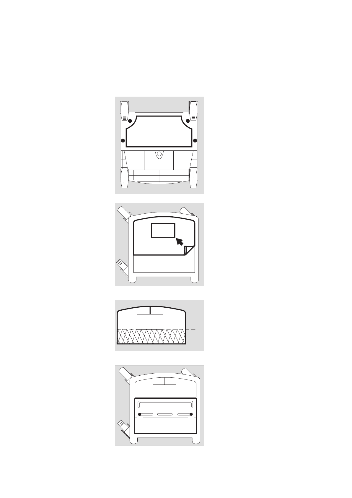
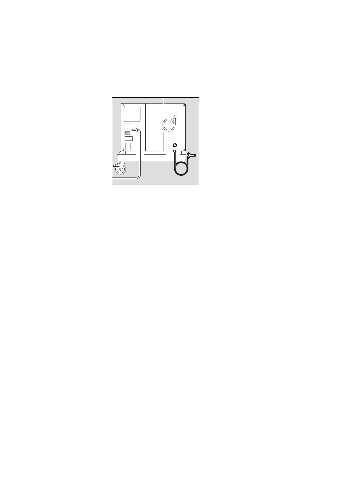
Auf das Evita Mobil-Fahrgestell
montieren
● Beatmungsgerät vom Evita Mobil-
Fahrgestell abnehmen.
● Evita Mobil-Fahrgestell auf den
Boden legen, dass die Unterseite
zugänglich ist.
1 Abluftkappe mit beiliegenden Kreuz-
schlitzschrauben unter den Rahmen
des Fahrgestells schrauben.
● Fahrgestell wieder auf die Rollen stel-
len.
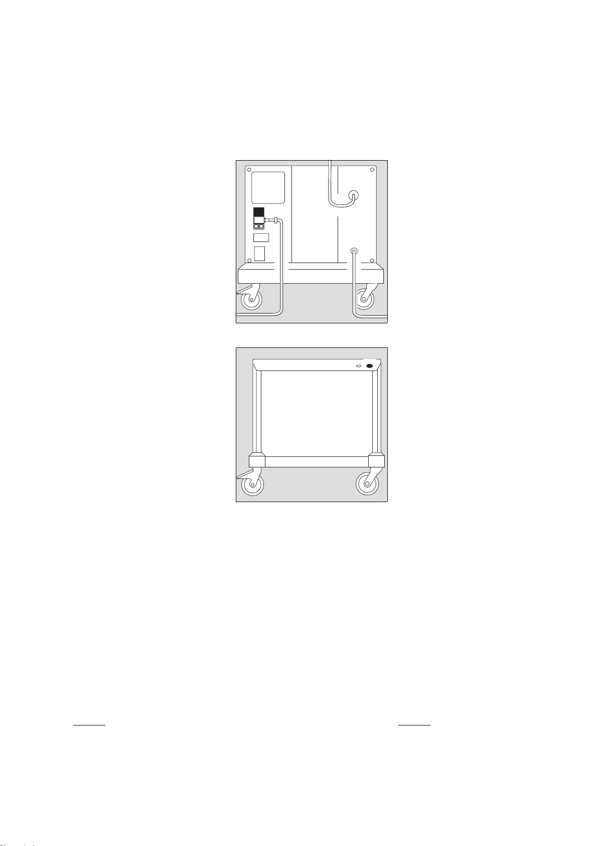
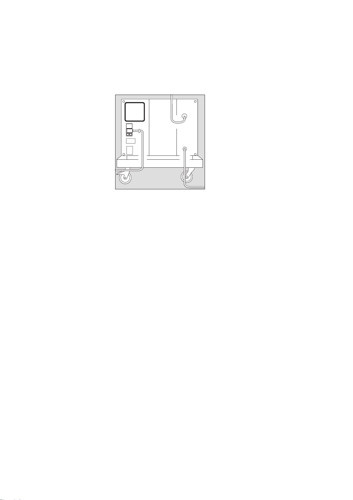
2 Schaumstoffmatte aus dem Fahrge-
stell herausnehmen.
● Schaumstoffmatte an der vorbereite-
ten Schnittstelle abschneiden.
3 Die beiden Teile wieder in das Fahr-
gestell einlegen.
4 Die beiden Schrauben der Batterie-
abdeckung herausschrauben, Batte-
rieabdeckung herausnehmen.
● Die beiden Schrauben unter der Bat-
terieabdeckung heraus-schrauben.
01429080
11
1
1
01529080
2
01629080
✂
33
01729080
44
Installing the compressor on
the Evita trolley
● Remove the ventilator from the Evita
trolley.
● Lay the Evita trolley on the ground so
that the underside is accessible.
1 Secure the exhaust air cover to the
trolley frame with the enclosed Phil-
lips screws.
● Turn the trolley upright again.
2 Remove the foam mat from the
trolley.
● Cut the foam mat off along the pre-
pared line.
3 Place both parts in the trolley.
4 Undo the two screws on the battery
compartment cover and remove the
cover.
● Undo the two screws below the bat-
tery compartment cover.
7
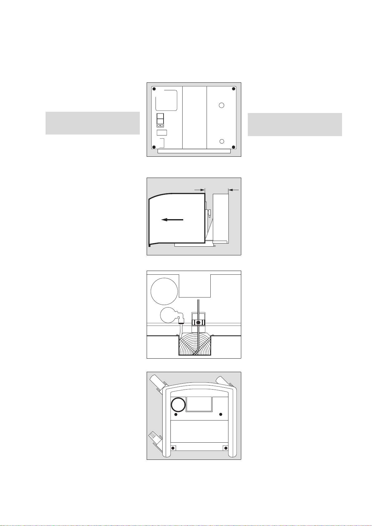
Vorbereiten Preparing for use
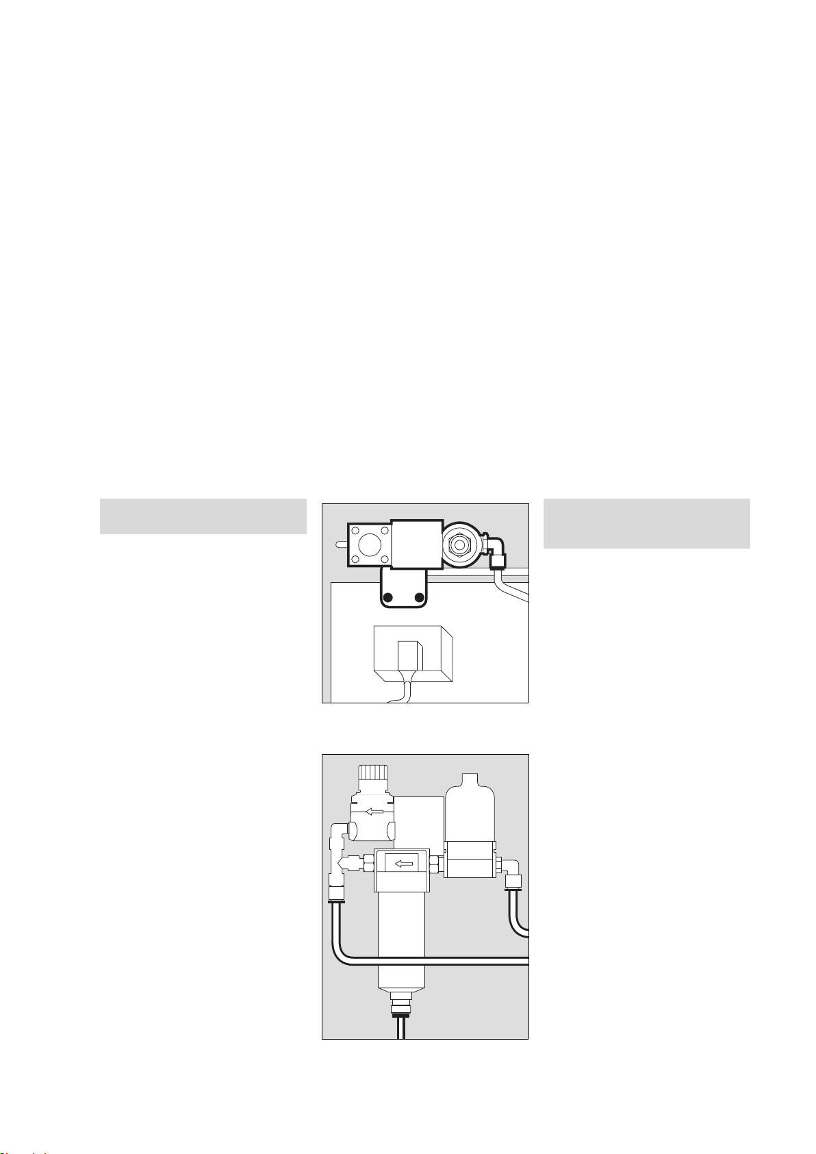
Am Kompressor:
1 Die vier Innensechskantschrauben
auf der Rückseite herausschrauben.
2 Die Haube vorsichtig nur ca. 10 cm
zurückziehen, dass das Kabel der
Anzeigelampe nicht abgerissen wird.
3 Kreuzschlitzschraube am Stecker
herausschrauben, Stecker ziehen,
Haube ganz abziehen.
4 Kompressor auf das Fahrgestell
stellen, Druckbehälter neben der
Säule platziert.
5 Kompressor mit den vier Innensechs-
kantschrauben und Unterlegschei-
ben am Fahrgestell festschrauben.
Sicherstellen, dass Netzstecker
gezogen, sonst Gefahr eines elektri-
schen Schlags!
00129080
1
1
1
1
00229080
2
ca. 10 cm/approx. 10 cm
01829080
3
00529080
5
5
4
55
On the compressor:
1 Undo the four Allen screws on the
rear of the compressor.
2 Carefully draw the shroud back
approx. 10 cm so that the indicator
lead is not pulled off.
3 Undo the Phillips screw on the plug
connector, unplug the connector and
remove the shroud completely.
4 Place the compressor on the trolley
with the pressure vessel alongside
the column.
5 Tightly secure the compressor to the
trolley with the four Allen screws and
washers.
Ensure that the mains power cable
has been unplugged in order to
avoid electric shocks!
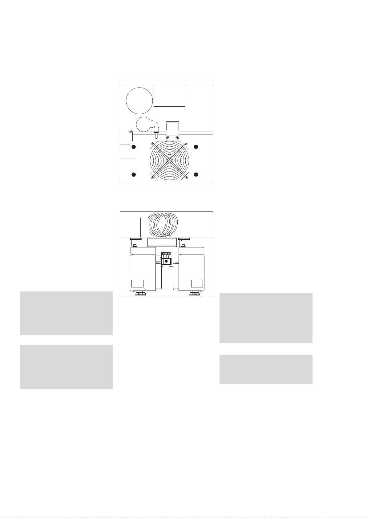
Vorbereiten
8
Preparing for use
1 Die vier Innensechskantschrauben
der Transportsicherung heraus-
schrauben.
2 Die beiden Laschen der Transport-
sicherung herausziehen.
3 Den Motorstecker stecken und mit
der Kreuzschlitzschraube sichern.
Laschen und Schrauben der Trans-
portsicherung für spätere Transporte
aufbewahren.
● Haube aufsetzen, deren Stecker
stecken und mit der Kreuzschlitz-
schraube sichern.
● Haube zuschieben und die vier
Innensechskantschrauben auf der
Rückseite hineinschrauben.
Vor jeder Erstinbetriebnahme
Transportsicherung abnehmen,
sonst entstehen starke Vibrationen
am Atemluftkompressor.
Das Kompressoraggregat kann
beschädigt werden!
Vor jedem Transport, der abweicht
vom betriebsgemäßen Transport im
Fahrgestell:
Transportsicherung einbauen, sonst
können die Gummifüße beschädigt
werden.
01929080
1
1
1
1
02029080
3
2 2
1 Undo the four Allen screws securing
the internal packing.
2 Pull out the two tabs on the internal
packing.
3 Plug in the motor connector and
secure it with the Phillips screw.
Keep the tabs and screws from the
internal packing for future use.
● Fit the shroud, plug in its connector
and secure it with the Phillips screw.
● Close the shroud and screw down
the four Allen screws on the rear of
the unit.
This safety mechanism must always
be removed before using the com-
pressor for the first time, otherwise
major vibrations may develop in the
compressor.
These may damage the compressor
unit!
The internal packing must be fitted
whenever the compressor is trans-
ported without its trolley, otherwise
the rubber feet may be damaged.
9
Vorbereiten Preparing for use
Auf den separaten
Fahrgestellfuß montieren
Montage des Kompressors wie für Evita
Mobil-Fahrgestell durchführen.
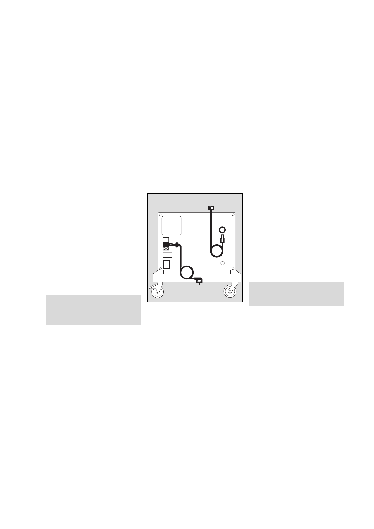
Kompressor anschließen
1 Sicherstellen, dass die Betriebsspan-
nung am Typenschild auf der Rück-
seite mit der Netzspannung
übereinstimmt.
2 Schelle abschrauben.
3 Gerätestecker stecken, Kabel straf-
fen, unter die Schelle klemmen
und
2 Schelle festschrauben.
4 Netzstecker in eine geerdete Steck-
dose stecken, keinen Adapterstecker
benutzen.
5 Druckluft-Anschlussschlauch am
Beatmungsgerät anschrauben.
6 Stecker des Druckluft-
Anschlussschlauchs fest in die Kupp-
lung des Kompressors stecken – bis
zum Einrasten.
● Kompressor an möglichst kühlem Ort
platzieren, nicht vor Heizungen oder
anderen Wärmequellen.
Für eine ungehinderte Luftzirkulation
um den Kompressor herum sorgen.
● Kompressor nicht in salzhaltiger Luft
betreiben, die Rückschlagventile im
Kompressor können korrodieren.
Nicht mehrere Beatmungsgeräte am
Kompressor anschließen!
Der Kompressor kann überlastet
werden.
02129080
5
6
4
1
2
3
Installing the compressor on a
seperate trolley
The compressor is installed in the same
way as on the Evita trolley.
Connecting the compressor
1 Check that the operating voltage
specified on the rating plate matches
the mains voltage.
2 Unscrew clamp.
3 Plug in apparatus connector, pull
cable until taut, secure under clamp
and
2 screw clamp back into place.
4 Plug the connector into an earthed
socket; do not use an adapter.
5 Screw the pressure hose onto the
ventilator.
6 Firmly insert the connector on the
pressure hose into the coupling on
the compressor – until it engages.
● Place the compressor in a cool place,
away from radiators and other
sources of heat.
Ensure that air can circulate freely
around the compressor.
● The compressor must not be oper-
ated in salty air, as this may cause the
non-return valves in the compressor
to corrode.
Do not connect more than one venti-
lator to the compressor!
It could overload the compressor.
Vorbereiten
10
Preparing for use
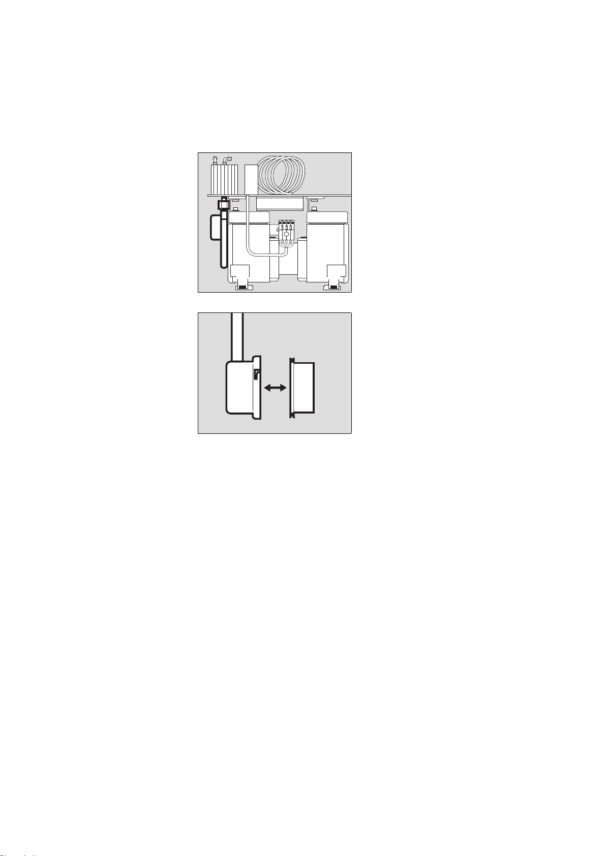
Für Standby-Funktion
(Option)
Zur Versorgung des Beatmungsgerätes
bei Ausfall des zentralen Druckluft-
systems.
1 Druckluft-Anschlussschlauch am
Kompressor anschrauben.
2 Stecker in die Wandentnahmestelle
des zentralen Druckluftsystems
stecken.
02229080
2
1
Standby mode
(optional)
For emergency supply if the central med-
ical air system fails.
1 Screw the pressure hose to the com-
pressor.
2 Plug the connector into the wall
socket of the central medical air sys-
tem.
11
Betrieb Operation
Betrieb
Wurde der Kompressor bei Temperatu-
ren unter 3 °C gelagert:
● Ca. 2 Stunden für Temperaturaus-
gleich abwarten.
1 Netzschalter auf der Rückseite
drücken,
2 die grüne Lampe »
N « vorn in der
Haube leuchtet = EIN.
● Das angeschlossene Beatmungsge-
rät einschalten.
Bei Betriebstörungen siehe "Fehler -
Ursache - Abhilfe", Seite 18.
Standby-Funktion
Zur Versorgung des Beatmungsgerätes
bei Ausfall des zentralen Druckluftsy-
stems.
● Netzschalter immer eingeschaltet
lassen = grüne Lampe » N « vorn in
der Haube leuchtet
Der eingeschaltete Kompressor über-
wacht den Druck im zentralen Druckluft-
system:
Fällt der Druck unter 2,7
–0,3 bar
1)
, über-
nimmt der Kompressor automatisch die
Druckluftversorgung des angeschlosse-
nen Beatmungsgerätes. Steigt der
Druck im zentralen Druckluftsystem wie-
der über 3,4 bar
2)
, schaltet der Kom-
pressor seine Versorgung ab und bleibt
in Standby.
Betriebsende
Nach dem Abschalten des Beatmungs-
gerätes:
● Netzschalter auf der Rückseite
drücken,
● die grüne Lampe » N « erlischt
= AUS.
Der Kompressor entlüftet sich auto-
matisch.
1)
US-Kompressor 115 V/60 Hz/Standby:
2,7±0,2 bar
2)
US-Kompressor 115 V/60 Hz/Standby:
3,2±0,2 bar
02329080
1
01029080
2
Operation
If the compressor has been stored at
temperatures below 3 °C:
● Wait approx. 2 hours for the com-
pressor to warm up.
1 Press main switch on rear,
2 the green LED »
N « in the front of
the shroud lights up = ON.
● Now switch on the ventilator.
Refer to "Fault - Cause - Remedy" on
page 19 if any faults develop.
Standby mode
For emergency supply if the central med-
ical air system fails.
● Always leave the main switch ON =
green LED » N « on front of shroud
lights up.
The pressure in the central medical air
system is monitored by the compressor
while switched on:
If the pressure drops below
2.7
–0.3 bar
1)
, the compressor automati-
cally supplies medical air to the ventila-
tor to which it is connected. The
compressor switches off the supply and
remains on standby when the pressure
in the central medical air system rises
above 3.4 bar
2)
.
Switching off
After switching off the ventilator:
● Press the main switch on the rear,
● the green LED » N « goes out
= OFF.
The compressor is vented automati-
cally.
1)
US Compressor 115 V/60 Hz/Standby:
2.7±0.2 bar
2)
US Compressor 115 V/60 Hz/Standby:
3.2±0.2 bar
Pflege
12
Routine maintenance
Pflege
Wenn die Filtermatte verschmutzt ist:
1 Filtermatte herausnehmen, Schmutz
ausklopfen, Filtermatte wieder
einsetzen.
● Schmutz am Gehäuse des Kompres-
sors mit einem Einwegtuch
entfernen.
Wischdesinfizieren des Gehäuses
Zur Desinfektion Präparate aus der
Gruppe der Flächendesinfektionsmittel
verwenden. Aus Gründen der Material-
verträglichkeit eignen sich Präparate auf
der Wirkstoffbasis von:
— Aldehyden,
— quaternären Ammoniumverbinungen.
Wegen möglicher Schädigung der Mate-
rialien eignen sich keine Präparate auf
der Basis von:
— Phenol-haltigen Verbindungen,
— Halogen-abspaltenden Verbindun-
gen,
— starken organischen Säuren,
— Sauerstoff-abspaltenden Verbindun-
gen.
● wischdesinfizieren
z.B. mit Incidur
®
(Fa. Ecolab
Deutschland GmbH)
● Anwendungsvorschriften des Her-
stellers beachten.
02429080
1
Routine maintenance
If the filter mat is soiled:
1 Remove the filter mat, knock out any
dirt and insert the mat again.
● Any dirt on the compressor housing
should be wiped off with a disposa-
ble cloth.
Wiping with disinfectant
A surface disinfectant can be used to
wipe the housing. Preparations based
on:
—aldehydes or
— quaternary ammonium compounds.
Preparations based on the following
compounds should not be used as they
may damage the housing:
— Compounds containing phenol,
— Compounds giving off halogens,
— Strong organic acids,
— Compounds giving off oxygen.
● Wipe with disinfectant e.g. Incidur
®
(Ecolab Deutschland GmbH)
● Note the manufacturer's instructions.
13
Instandhaltungsintervalle Maintenance intervals
Instandhaltungsintervalle
Instandhaltung durch Fachleute
Im Bedarfsfall Instandhaltung in kürze-
ren Intervallen durchführen.
War das Gerät keine 6000 Stunden in
Betrieb:
● Nach spätestens einem Jahr Inspek-
tion und Wartung durchführen.
Verschmutzte Filter mit dem Hausmüll
entsorgen.
Filtergruppe ausbauen
Gehäuse abnehmen, siehe Seite 7.
1 Beide Kreuzschlitzschrauben heraus-
schrauben.
2 Schläuche abnehmen:
Ring zurückgedrückt halten und
gleichzeitig Schlauch aus dem
Anschluss ziehen.
● Filtergruppe herausnehmen.
spätestens alle 6000
Betriebsstunden:
(siehe Betriebs-
stundenzähler)
Filterwechsel für
Vorfilter,
Hauptfilter,
Ansaugfilter
Netzstecker ziehen! Sonst Gefahr
eines elektrischen Schlags!
03029080
1
1
02829080
2
2
2
Maintenance intervals
Maintenance work may only be carried
out specially trained service personnel.
Carry out maintenance more frequently
if necessary.
If the apparatus has not been in opera-
tion for 6000 hours:
● Carry out inspection and servicing
after not more than a year.
Dispose of used filters with domestic
waste.
Removing the filter group
Remove the housing, see page 7.
1 Undo both Phillips screws.
2 Disconnect the hoses:
Pull back and hold the ring while pull-
ing the hose from the socket at the
same time.
● Remove the filter group.
at least every
6000 hours:
(see operating hours
counter)
Change filters
in prefilter,
main filter and
intake filter
The apparatus must always be
unplugged from the mains in order
to avoid electric shocks!
Instandhaltungsintervalle
14
Maintenance intervals
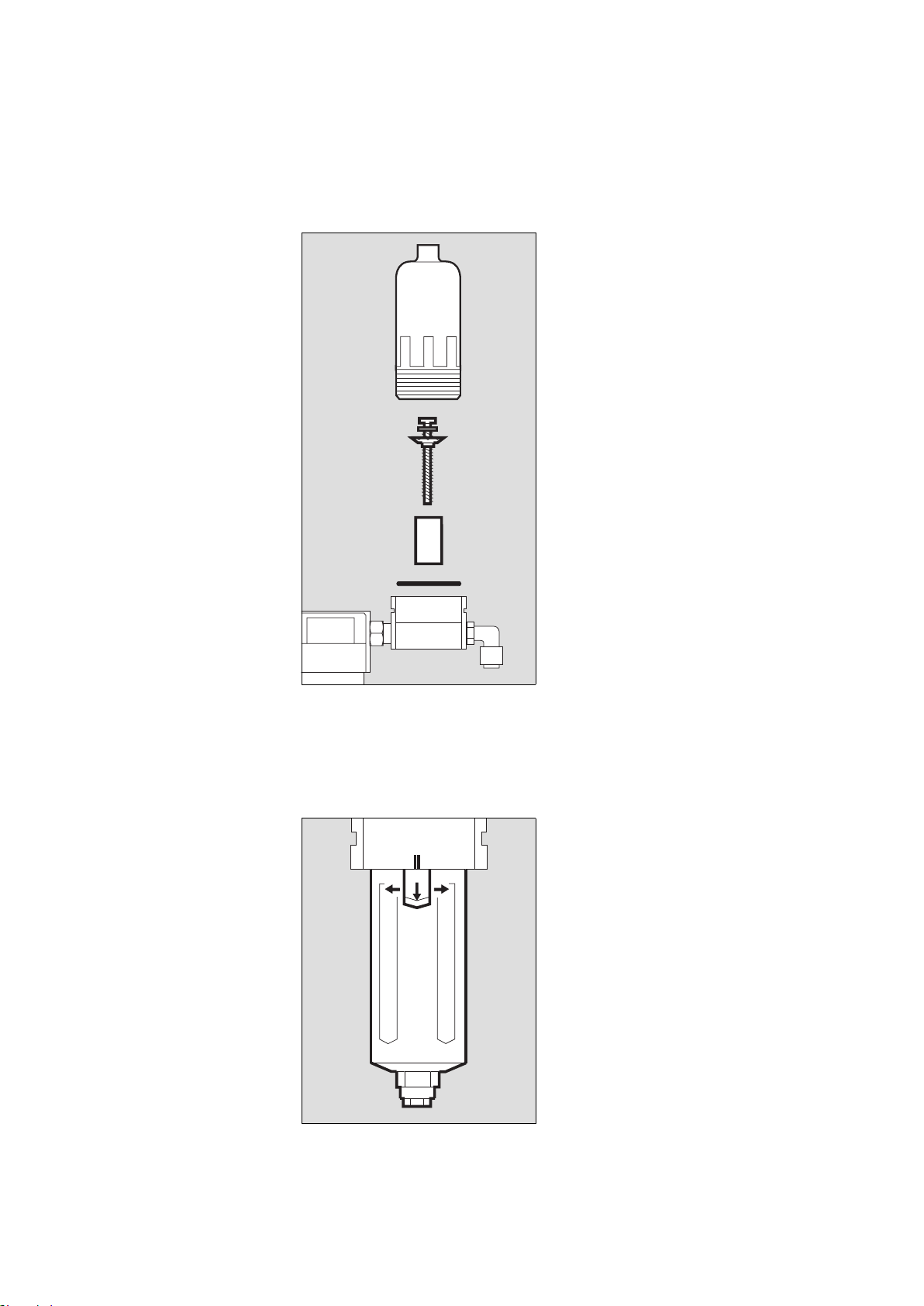
Vorfilter wechseln
1 Gehäuse mit der Hand abschrauben.
2 Kreuzschlitz-Schraube abschrauben
und mit Kunststoffscheibe abneh-
men.
3 Filterhülse herausnehmen und
gegen eine Neue wechseln.
3 Neue Filterhülse einsetzen.
2 Mit Kreuzschlitz-Schraube und Kunst-
stoffscheibe festschrauben.
4 Alten O-Ring herausnehmen, neuen
O-Ring einlegen.
● Gehäuse fest mit der Hand anschrau-
ben.
Hauptfilter wechseln
5 Klinke gezogen halten und
gleichzeitig
6 Gehäuse drehen, bis sich die
Markierungen ( II ) decken.
● Gehäuse abziehen.
03129080
1
2
3
4
02629080
5
66
Changing the prefilter
1 Unscrew the housing by hand.
2 Unscrew recessed head screw and
remove screw and plastic washer.
3 Remove the filter sleeve and replace.
3 Insert the new filter sleeve.
2 Fasten in place with recessed head
screw and plastic washer.
4 Remove old O-ring and fit new O-ring.
● Screw housing together by hand.
Changing the main filter
5 Pull and hold the catch while simulta-
neously
6 turning the housing until the
marks ( II ) line up.
● Remove the housing.
15
Instandhaltungsintervalle Maintenance intervals
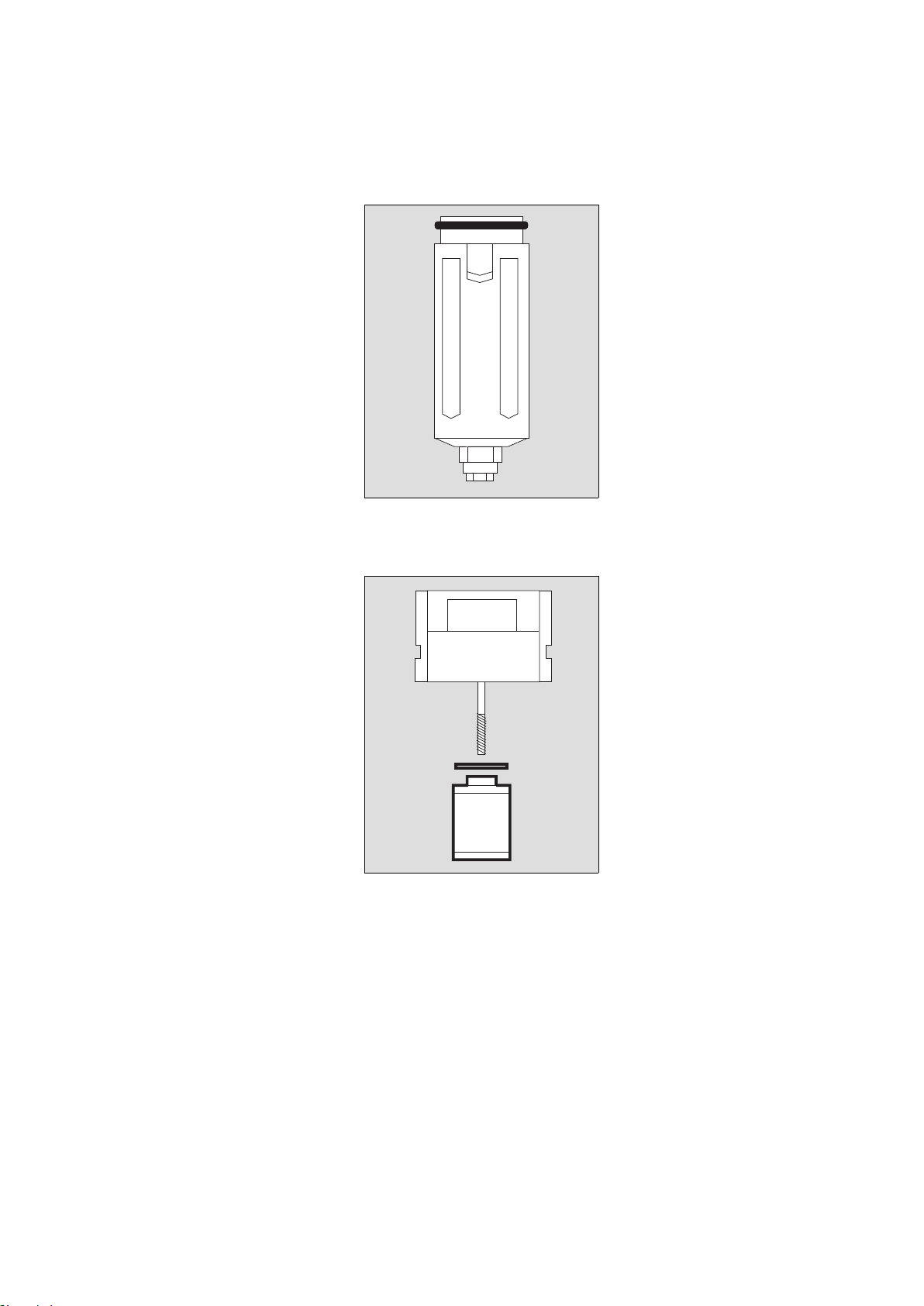
1 Alten O-Ring vom Gehäuse abneh-
men, neuen O-Ring montieren.
2 Alte Filterhülse mit der Hand heraus-
schrauben und neue Filterhülse ein-
schrauben.
● Gehäuse so einsetzen, dass sich die
Markierungen decken und drehen
bis die Klinke hörbar einrastet.
● Mit leichtem Zug am Gehäuse
prüfen, ob das Gehäuse eingerastet
ist.
03729080
1
02729080
2
1 Remove old O-ring from housing and
fit new O-ring.
2 Unscrew old filter sleeve by hand and
screw in new filter sleeve.
● Insert the housing so that the marks
line up, then turn until the catch is
heard to engage.
● Lightly pull the housing to ensure that
it has engaged.
Instandhaltungsintervalle
16
Maintenance intervals
Ansaugfilter wechseln
1 Die jeweils zwei Innensechskant-
schrauben an den vorderen und hin-
teren Montageblechen des
Kompressoraggregats heraus-
schrauben.
2 Druckluftschlauch mit Gabel-
schlüssel SW 19 abschrauben, mit
einem zweiten Maulschlüssel das
Verbindungsstück zum Wärme-
tauscher vor Losdrehen sichern.
● Das Kompressoraggregat soweit her-
ausziehen, bis das rückseitige Aus-
gangsrohr des Filtergehäuses nicht
mehr aus der Bohrung ragt.
3 Filtergehäuse im Uhrzeigersinn dre-
hen und abnehmen.
4 Altes Ansaugfilter herausnehmen
und ein Neues ins Filtergehäuse ein-
setzen.
● Filtergehäuse aufsetzen, das Rohr
nach hinten zeigend ca. auf Position
"11 Uhr".
3 Filtergehäuse gegen Uhrzeigersinn
drehen, bis es verriegelt ist. Rohr ist
in horizontaler Position.
● Durch Ziehen den festen Sitz des Fil-
tergehäuses prüfen.
● Kompressoraggregat zurückschie-
ben, dabei das Rohr in die Bohrung
einführen.
2 Druckluftschlauch mit Gabel-
schlüssel SW 19 festschrauben, mit
einem zweiten Maulschlüssel das
Verbindungsstück zum Wärmetau-
scher vor Losdrehen sichern.
1 Kompressoraggregat vorn und hinten
mit jeweils zwei Innensechskant-
schrauben festschrauben.
03329080
3
1
1
2
03229080
4
Changing the intake filter
1 Remove the two Allen screws on the
front of the assembly plates of the
compressor unit and undo the two
rear Allen screws two turns.
2 Unscrew the pressure hose with a
size 19 fork wrench and hold the con-
nector to the heat exchanger with a
second spanner to prevent it working
loose.
● Pull the compressor unit out until the
outlet pipe at the rear of the filter
housing no longer protrudes from the
hole.
3 Turn the filter housing clockwise and
remove it.
4 Remove the old intake filter and
insert a new filter in the filter housing.
● Position the filter housing with the
pipe facing to the rear in a position
corresponding roughly to
"11 o'clock".
3 Turn the filter housing anticlockwise
until locked. The pipe is now horizon-
tal.
● Pull gently to check that the filter
housing is secure.
● Push the compressor unit back, guid-
ing the pipe into the hole at the same
time.
2 Secure the pressure hose with a size
19 fork wrench and hold the connec-
tor to the heat exchanger with a sec-
ond spanner to prevent it working
loose.
1 Secure the compressor unit with the
front and rear Allen screws.
17
Instandhaltungsintervalle Maintenance intervals
Filtergruppe einbauen
● Schläuche an der Filtergruppe
anschließen, s. Seite 13.
● Filtergruppe festschrauben,
s. Seite 13.
● Haube aufsetzen, deren elektrischen
Stecker stecken und mit der Kreuz-
schlitzschraube sichern.
● Haube zuschieben und die vier
Innensechskantschrauben auf der
Rückseite hereinschrauben.
Sicherungen wechseln
● Netzstecker ziehen.
1 Kappen mit Schraubendreher gegen
den Uhrzeigersinn drehen und her-
ausnehmen.
2 Durchgebrannte Sicherungen aus
den Kappen ziehen und neue Siche-
rungen in die Kappen stecken – Nur
die vorgeschriebenen Sicherungen
verwenden, siehe "Technische
Daten", Seite 21.
1 Kappen mit den neuen Sicherungen
wieder hereindrehen.
Gerät entsorgen
— am Ende der Nutzungsphase.
● Gerät nach Rücksprache mit den
zuständigen Entsorgungsunterneh-
men der fachgerechten Entsorgung
zuführen. Die geltenden gesetzlichen
Vorschriften beachten!
Dieses Gerät fällt in den Geltungsbe-
reich der EU-Richtlinie 2002/96/EG
(WEEE). Es ist nicht für die Nutzung in
privaten Haushalten registriert, eine Ent-
sorgung über die kommunalen Sammel-
stellen für Elektroaltgeräte ist nicht
zulässig.
Dräger Medical hat ein Unternehmen
autorisiert, die rechtssichere Entsor-
gung dieses Gerätes vorzunehmen: Für
nähere Informationen wenden Sie sich
bitte an die für Sie zuständige nationale
Dräger Medical Organisation.
03529080
2
1
Installing the filter group
● Connect the hoses to the filter group,
see page 13.
● Screw the filter group into place, see
page 13.
● Fit the shroud, plug in its connector
and secure it with the Phillips screw.
● Close the shroud and screw down
the four Allen screws on the rear of
the unit.
Replacing the fuses
● Unplug the mains connector.
1 Turn the caps anticlockwise with a
screwdriver and remove them.
2 Remove blown fuses from their caps
and insert new fuses. Only the speci-
fied fuses may be used, see "Techni-
cal data" on page 21.
1 Screw the caps with the new fuses
back into place.
Disposal of the device
— at the end of its useful life.
● After contacting the competent spe-
cialised waste disposal companies,
send the device to the appropriate
expert disposal facility. Observe all
applicable legal requirements.
This device is subject to EU Directive
2002/96/EC (WEEE). It is not regis-
tered for use in private households, and
may not be disposed of at municipal col-
lection points for waste electrical and
electronic equipment.
Dräger Medical has authorized a firm to
dispose of this device in the proper man-
ner: for more detailed information,
please contact your local Dräger Medi-
cal organization.

Fehler - Ursache - Abhilfe
18
Fehler - Ursache - Abhilfe
1)
US-Kompressor 115 V/60 Hz/Standby:
2,7±0,2 bar
Fehler Ursache Abhilfe
Kompressor vibriert stark Transportsicherung
wurde nicht ausgebaut
Transportsicherung aus-
bauen, Seite 8
Gummifüße am Kompres-
soraggregat defekt
DrägerService in
Anspruch nehmen
Kompressor läuft, erzeugt
jedoch keinen oder einen
zu geringen Druck
Ansaugfilter verschmutzt Ansaugfilter wechseln,
Seite 15
Undichtheiten an den
Komponenten des Atem-
luftkompressors
DrägerService in
Anspruch nehmen
Rote Lampe »Temp
[«
leuchtet, begleitet von
einem schnarrenden
Alarmton
hohe Umgebungs-
temperatur
Kompressor an kühlem
Ort platzieren, für eine
ungehinderte Luftzirkula-
tion sorgen
Filtermatte verschmutzt Schmutz aus Filtermatte
ausklopfen oder neue
Filtermatte einsetzen
Lüfter defekt DrägerService in
Anspruch nehmen
Kompressor läuft nicht an keine Netzspannung
oder zu niedrige Netz-
spannung
Netzspannung prüfen
Sicherungen defekt Sicherungen aus-
tauschen, Seite 17
Gerät defekt DrägerService in
Anspruch nehmen
Für Standby-Geräte:
Kompressor läuft an,
obwohl der Druck in der
zentralen Versorgung
mehr als 2,7
–0,3 bar
1)
beträgt
Druckschalter defekt DrägerService in
Anspruch nehmen

Fault - Cause - Remedy
19
Fault - Cause - Remedy
1)
US Compressor 115 V/60 Hz/Standby:
2.7±0.2 bar
Fault Cause Remedy
Compressor vibrates
strongly
Internal packing has
not been removed
Remove internal packing,
page 8
Rubber feet on compres-
sor unit defective
Call DrägerService
Compressor runs, but
builds up too little or no
pressure
Intake filter soiled Replace intake filter,
page 15
Leaks in the compressor
components
Call DrägerService
Red LED »Temp
[«
lights up and an alarm
sounds
High ambient tempera-
ture
Place the compressor in a
cool place and ensure
free air circulation
Filter mat soiled Knock dirt out of filter mat
or fit a new filter mat
Fan defective Call DrägerService
Compressor refuses to
start
Mains voltage too low or
not available
Mains voltage too low or
not available
Fuses defective Replace fuses, page 17
Apparatus defective Call DrägerService
Standby apparatus:
Compressor starts up
although pressure in
central medical air supply
is over 2.7
-0.3 bar
1)
Pressure switch
defective
Pressure switch
defective
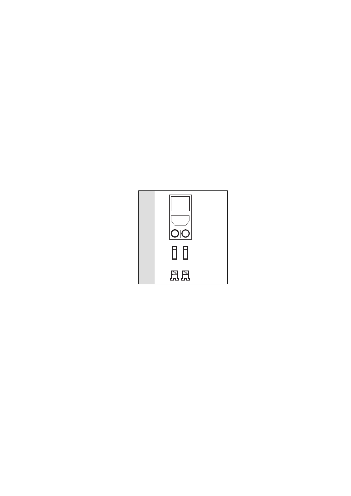
20
Was ist was What's what
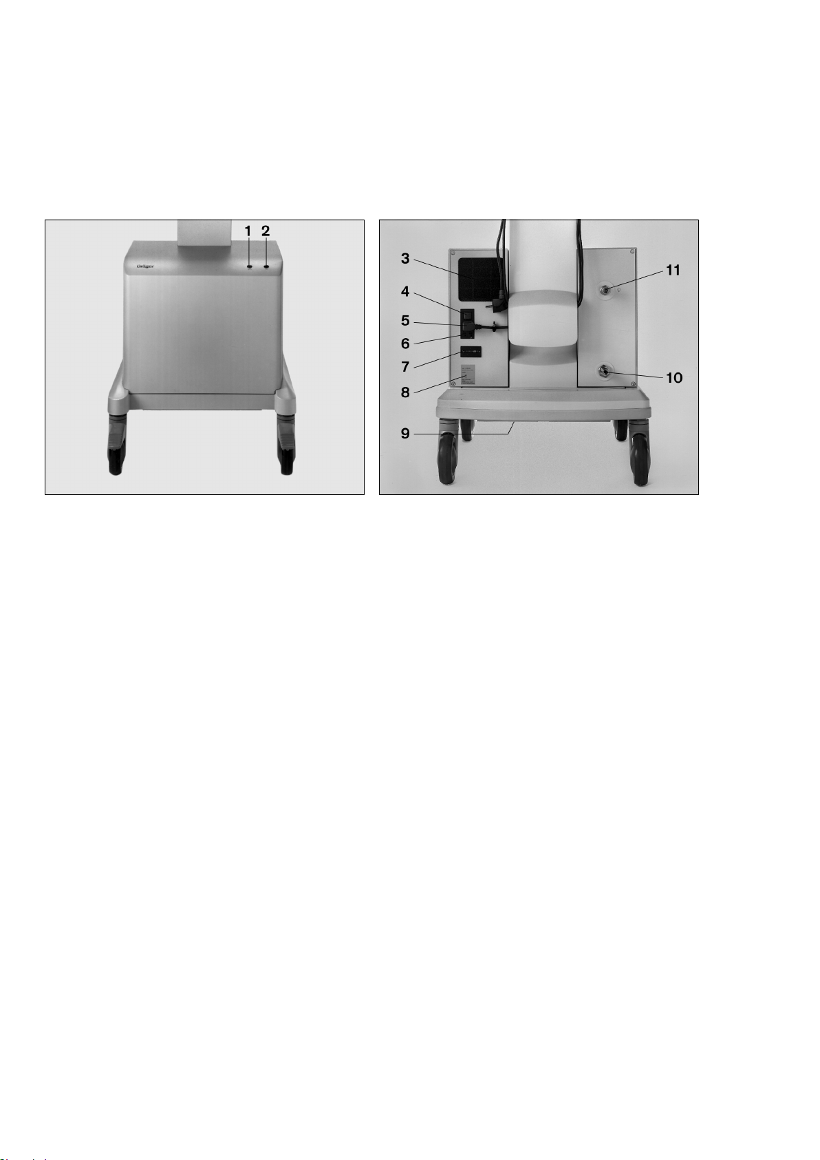
Was ist was
1 Rote Lampe »Temp [« für Übertemperatur
2 Grüne Lampe »
N « für Betrieb/ Bereitschaft
3 Filtermatte
4 Netzschalter
5 Netzkabel
6 Sicherungen
7 Betriebsstundenzähler
8 Typenschild
9 Abluftkanal
10 Anschluss für Druckluft-Anschlussschlauch der zentralen
Druckluftversorgung (nur bei Standby-Geräten)
11 Kupplung für Druckluft-Anschlussschlauch des
Beatmungsgerätes
MT-780-97
What's what
1 Red LED »Temp [« when temperature is too high
2 Green LED »
N « indicates power on / standby
3 Filter mat
4 Main switch
5 Power cable
6 Fuses
7 Operating hours counter
8 Rating plate
9 Exhaust air duct
10 Connection for pressure hose from central medical air
supply (standby apparatus only)
11 Coupling for pressure hose from ventilator
MT-781-97

21
Technische Daten Technical Data
Technische Daten
US-Kompressor 115 V/60 Hz/Standby:
1)
Druckluftversorgung
EIN <2,7±0,2 bar
2)
Druckluftversorgung
AUS >3,2±0,2 bar
Umgebungsbedingungen
Betrieb:
Temperatur 10 bis 40
o
C
Rel. Luftfeuchte 30 bis 95 %, keine Betauung
Höhe über dem
Meeresspiegel 0 bis 4000 m
Lagerung:
Temperatur –20 bis 70
o
C
Rel. Luftfeuchte 0 bis 99 %, keine Betauung
Höhe über dem
Meeresspiegel 0 bis 16000 m
Leistungskennwerte
Betriebsdruck 4+0,5 bar
Dauerflow minimal 30 L/min bei 3,0 bar
Spitzenflow 180 L/min für max. 0,8 Sekunden
bei insgesamt max. 30 L/min
Taupunktreduzierung
bei Betriebsdruck
5
o
C unter Umgebungstemperatur
bei ≥30 L/min und max. Umge-
bungstemperatur 40
o
C.
15
o
C unter Umgebungstempera-
tur bei 15 L/min und max. Umge-
bungstemperatur 40
o
C
Luftqualität Staub- und ölfreie Druckluft
Filter ≤1 µm
Druckluftausgang Verschlusskupplung
Alarm Übertemperaturalarm, optisch
(rote Lampe) und akustisch (Sum-
mer mit Dauerton)
Standby – Drucküberwachung
Kompressor – Druck-
luftversorgung EIN
<2,7–0,3 bar
1)
Kompressor – Druck-
luftversorgung AUS
>3,4 bar
2)
Technical Data
US Compressor 115 V/60 Hz/Standby:
1)
medical air
ON <2.7±0.2 bar
2)
medical air
OFF >3.2±0.2 bar
Ambient conditions
Operation:
Temperature 10 to 40
o
C
Relative humidity 30 to 95 %, no condensation
Height above sea level 0 to 4000 m
Storage:
Temperature –20 to 70
o
C
Relative humidity 0 to 99 %, no condensation
Height above sea level 0 to 16000 m
Performance characteristics
Operating pressure 4+0.5 bar
Continuous flow Minimum 30 L/min at 3.0 bar
Peak flow 180 L/min for max. 0.8 seconds at
a total of max. 30 L/min
Dew point depression
under operating
pressure
5
o
C below ambient temperature
at ≥30 L/min and max. ambient
temperature 40
o
C.
15
o
C below ambient temperature
at 15 L/min and max. ambient tem-
perature 40
o
C
Air quality Dust-free and oil-free compressed
air
Filter ≤1 micron
Compressed air outlet Coupling with check valve
Alarm High temperature alarm, visual
(red LED) and acoustic
(continuous buzzer)
Standby – pressure monitoring
Compressor – medical
air ON
<2.7–0.3 bar
1)
Compressor – medical
air OFF
>3.4 bar
2)

22
Technische Daten Technical Data
Betriebskennwerte
1)
NIST = Non Interchangeable Screw Thread
(unvertauschbarer Anschluss)
2)
DISS = Diameter Indexed Safety System
(unvertauschbarer Anschluss)
Anschluss für zentrales
Druckluftsystem
NIST
1)
-Anschluss oder
DISS
2)
-Anschluss
Nennspannung [V] Stromaufnahme
[A]
Sicherungen
bei 50 Hz bei 60 Hz IEC 127-2/V
230 2,3 2,4 T4H250V
Andere Varianten
100 5,9 5,9 T8H250V
110 4,9 5,2 T8H250V
115 4,7 5,0 T8H250V
127 4,2 4,5 T8H250V
Elektromagnetische
Verträglichkeit EMV
geprüft nach EN 60601-1-2
Schalldruckpegel
50 Hz-Geräte typ. 46 - 49 dB (A)
Schalldruckpegel
60 Hz-Geräte typ. 49 - 52 dB (A)
Gewicht ca. 45 kg
Abmessungen
(B x H x T) 50 x 38 x 41 cm
Klassifizierung
gemäß Richtlinie 93/42/EWG
Anhang IX
II a
UMDNS-Code
Universal Medical Device
Nomenclature System -
Nomenklatur für Medizingeräte
10-972
Operating characteristics
1)
NIST = Non Interchangeable Screw Thread
2)
DISS = Diameter Indexed Safety System
Connection for central
medical air system
NIST
1)
or
DISS
2)
connection
Nominal voltage [V] Current consumption
[A]
Fuses
at 50 Hz at 60 Hz IEC 127-2/V
230 2.3 2.4 T4H250V
Other versions
100 5.9 5.9 T8H250V
110 4.9 5.2 T8H250V
115 4.7 5.0 T8H250V
127 4.2 4.5 T8H250V
Electromagnetic
compatibility EMC
Tested to EN 60601-1-2
Sound pressure level
50 Hz-Systems: Typically 46 - 49 dB (A)
Sound pressure level
60 Hz-Systems: Typically 49 - 52 dB (A)
Weight Approx. 45 kg
Dimensions
(W x H x D) 50 x 38 x 41 cm
Classification
as per EC Directive 93/42/EEC
Annex IX
II a
UMDNS-Code
Universal Medical Device
Nomenclature System -
Nomenclature for medical
products
10-972
23
Funktionsbeschreibung Functional description
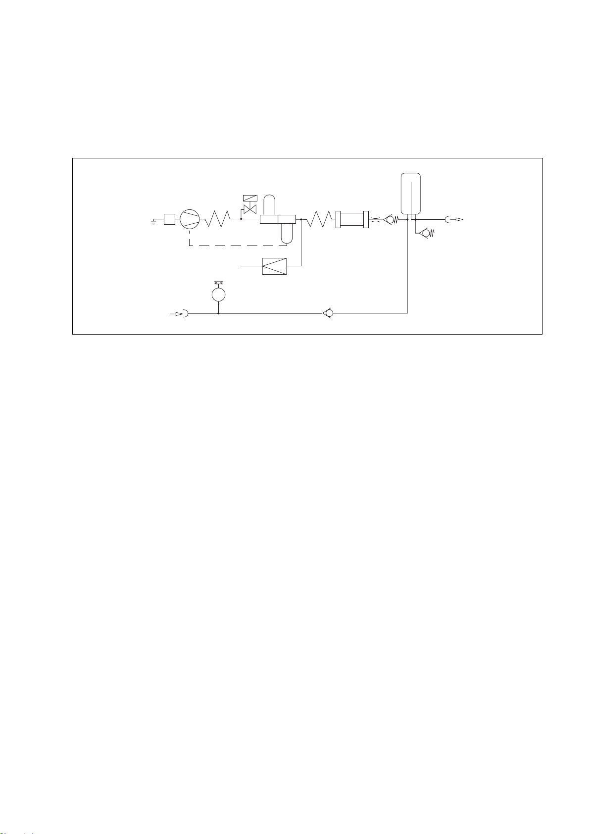
Funktionsbeschreibung
1 Ansaugfilter
2 Kompressoraggregat
3 Kühlspirale
4 Magnetventil
5 Vorfilter
6 Kondensatabscheider
7 Wärmetauscher
8 Druckbegrenzer
9 Membrantrockner
10 Drosseldüse
11 Rückschlagventil
12 Druckbehälter
13 Druckluftausgang
14 Sicherheitsventil
15 Eingang für Standby-Funktion
16 Druckschalter
17 Rückschlagventil
Umgebungsluft wird über das Ansaugfilter 1 angesaugt, im
Kompressoraggregat 2 verdichtet und in der Kühlspirale 3
gekühlt. Das Magnetventil 4 öffnet das System kurzzeitig beim
Start des Kompressors.
Die verdichtete Luft wird im Vorfilter 5 gereinigt, Kondensat
wird im Kondensatabscheider 6 separiert und abgeführt.
Die so behandelte Luft wird im Wärmetauscher 7 wieder
erwärmt, um einen weiteren Kondensatausfall vor dem
Membrantrockner 9 zu vermeiden.
Im nachgeschalteten Membrantrockner 9 wird die Luft auf
einen Taupunkt von mindestens 5
o
C unter Umgebungstem-
peratur entfeuchtet.
03429080
1
2
3
4
5
8
6
9
10
11
12
13
15
16
17
14
7
Functional description
1 Intake filter
2 Compressor unit
3 Cooling coil
4 Solenoid valve
5 Prefilter
6 Condensate trap
7 Heat exchanger
8 Pressure limiter
9 Diaphragm drier
10 Restrictor nozzle
11 Non-return valve
12 Pressure vessel
13 Medical air outlet
14 Relief valve
15 Input for standby mode
16 Pressure switch
17 Non-return valve
Ambient air is drawn in via the intake filter 1, compressed in
the compressor unit 2 and cooled in the cooling coil 3. The
system is briefly opened by solenoid valve 4 when the com-
pressor starts up.
The compressed air is cleaned by prefilter 5. Condensate is
collected and removed in the condensate trap 6.
The purified air is re-heated by the heat exchanger 7 in order to
prevent further condensation forming before it reaches the
diaphragm drier 9.
In the diaphragm drier 9, the air is dehumidified to a dew point
at least 5
o
C below the ambient temperature.

24
Funktionsbeschreibung Functional description
Die entfeuchtete Luft gelangt über Drosseldüse 10 und Rück-
schlagventil 11 in den Druckbehälter 12, wo sie über die
Kupplung 14 entnommen wird.
In Standby-Funktion wird das Beatmungsgerät aus der zentra-
len Druckluftversorgung über die Kupplung 15, Rückschlag-
ventil 17 und selbstschließende Kupplung 13 versorgt. Das
Kompressoraggregat 2 ist in Standby.
Wenn der Druck in der zentralen Versorgung unter
2,7
–0,3 bar
1)
absinkt, schaltet der Druckschalter 16 das Kom-
pressoraggregat 2 ein.
Steigt der Druck in der zentralen Versorgung auf 3,4 bar
2)
,
schaltet der Druckschalter 16 das Kompressoraggregat 2
wieder aus.
Der Druckregler 8 begrenzt den Systemdruck auf 4 bar, das
Sicherheitsventil 14 schützt vor einem zu hohen Druck aus der
zentralen Versorgung.
1)
US-Kompressor 115 V/60 Hz/Standby:
2,7±0,2 bar
2)
US-Kompressor 115 V/60 Hz/Standby:
3,2±0,2 bar
The dehumidified air flows via the restrictor nozzle 10 and non-
return valve 11 to the pressure vessel 12, where it is with-
drawn via the coupling 14.
In standby mode, the ventilator draws air from the central med-
ical air supply via the coupling 15, non-return valve 17 and
self-closing coupling 13. The compressor unit 2 is on standby.
If the pressure in the central medical air supply drops below
2.7
–0,3 bar
1)
, the compressor unit 2 is activated via pressure
switch 16.
When the pressure in the central medical air supply reaches
3.4 bar
2)
again, the compressor unit 2 is switched off again by
the pressure switch 16.
Pressure regulator 8 limits the system pressure to 4 bar and
relief valve 14 protects the unit against excessively high pres-
sure from the central medical air supply.
1)
US Compressor 115 V/60 Hz/Standby:
2.7±0.2 bar
2)
US Compressor 115 V/60 Hz/Standby:
3.2±0.2 bar

25
Bestell-Liste Order List
Bestell-Liste
Benennung Sach-Nr.
System Atemluftkompressor 84 14 350
Atemluftkompressor
Standardversion 230 V, 50 Hz 84 13 890
Option für Standby-Funktion 84 13 939
Druckluft-Anschlussschläuche für
Betrieb des Kompressors im Fahrgestell
von Evita:
NIST-Anschlussschlauch 0,8 m schwarz 84 11 517
NIST-Anschlussschlauch 0,8 m
Gaskennfarbe nach ISO 32 84 11 538
DISS-Anschlussschlauch 0,8 m gelb 84 14 454
Set – Austauschteile für 6000-Stunden
Wartung für Atemluftkompressoren ab
ARMJ 0020 (siehe Typenschild) 84 14 501
Alternativ zum Anschlussschlauch 0,8 m:
NIST-Anschlussschlauch 5 m schwarz 84 11 519
NIST-Anschlussschlauch 5 m
Gaskennfarbe nach ISO 32 84 11 541
Für Standby-Funktion:
NIST-Druckluft- Anschlussschlauch 3 m M 34 408
NIST-Druckluft- Anschlussschlauch 5 m M 34 409
Fahrgestellfuß 84 11 520
Technische Unterlagen auf Anfrage
Order List
Description Order No.
Medical air compressor system 84 14 350
Medical air compressor
Standard version 230 V, 50 Hz 84 13 890
Option for standby mode 84 13 939
Pressure hoses for operating the
compressor on the Evita trolley:
NIST connecting hose 0.8 m, black 84 11 517
NIST connecting hose 0.8 m,
gas colour-coding to ISO 32 84 11 538
DISS connecting hose 0.8 m, yellow 84 14 454
Set of replacement parts for the
6000 hour service for medical air
compressors from ARMJ 0020
(see rating plate) 84 14 501
The following hoses may be ordered
instead of the 0.8 m hose:
NIST connecting hose 5 m, black 84 11 519
NIST connecting hose 5 m,
gas colour-coding to ISO 32 84 11 541
For standby mode:
NIST medical air connecting hose 3 m M 34 408
NIST medical air connecting hose 3 m M 34 409
Trolley 84 11 520
Technical documentation on request

Répertoire
26
Índice
Répertoire
Pour votre sécurité, et pour celle de vos patients . . . . . . 27
Consignes pour une utilisation sûre . . . . . . . . . . . . . . . . . . . 28
Utilisation . . . . . . . . . . . . . . . . . . . . . . . . . . . . . . . . . . . . . . . . . 29
Préparation . . . . . . . . . . . . . . . . . . . . . . . . . . . . . . . . . . . . . . . 29
Avant la première mise en service . . . . . . . . . . . . . . . . . . . . . 29
Montage sur le chariot Evita . . . . . . . . . . . . . . . . . . . . . . . . . . 30
Montage sur le chariot séparé pour compresseur seul . . . 33
Branchement du compresseur . . . . . . . . . . . . . . . . . . . . . . . 33
Pour mode de fonctionnement en veille (Option) . . . . . . . . 34
Fonctionnement . . . . . . . . . . . . . . . . . . . . . . . . . . . . . . . . . . . 35
Mode de fonctionnement en veille . . . . . . . . . . . . . . . . . . . . 35
Arrêt . . . . . . . . . . . . . . . . . . . . . . . . . . . . . . . . . . . . . . . . . . . . . . 35
Entretien . . . . . . . . . . . . . . . . . . . . . . . . . . . . . . . . . . . . . . . . . . 36
Périodicité de maintenance . . . . . . . . . . . . . . . . . . . . . . . . . . 37
Dépose du groupe de filtres . . . . . . . . . . . . . . . . . . . . . . . . . 37
Remplacement du filtre préalable . . . . . . . . . . . . . . . . . . . . . 38
Remplacement du filtre principal . . . . . . . . . . . . . . . . . . . . . . 38
Remplacement du filtre d’aspiration . . . . . . . . . . . . . . . . . . . 40
Montage du groupe de filtres . . . . . . . . . . . . . . . . . . . . . . . . 41
Remplacement des fusibles . . . . . . . . . . . . . . . . . . . . . . . . . . 41
Incidents, causes et remèdes . . . . . . . . . . . . . . . . . . . . . . . 42
Vue d’ensemble et légendes . . . . . . . . . . . . . . . . . . . . . . . . 44
Caractéristiques techniques . . . . . . . . . . . . . . . . . . . . . . . 45
Description du fonctionnement . . . . . . . . . . . . . . . . . . . . . . 47
Liste des pièces . . . . . . . . . . . . . . . . . . . . . . . . . . . . . . . . . . . 49
Índice
Para su seguridad y la de sus pacientes . . . . . . . . . . . . . 27
Indicaciones para el uso seguro . . . . . . . . . . . . . . . . . . . . . . 28
Empleo . . . . . . . . . . . . . . . . . . . . . . . . . . . . . . . . . . . . . . . . . . . 29
Preparación . . . . . . . . . . . . . . . . . . . . . . . . . . . . . . . . . . . . . . . 29
Antes de la primera puesta en servicio . . . . . . . . . . . . . . . . . 29
Montaje sobre el soporte móvil Evita . . . . . . . . . . . . . . . . . . 30
Montaje en el soporte móvil adicional . . . . . . . . . . . . . . . . . . 33
Conexión del compresor . . . . . . . . . . . . . . . . . . . . . . . . . . . . 33
Para modo en espera (standby) (Opción) . . . . . . . . . . . . . . 34
Funcionamiento . . . . . . . . . . . . . . . . . . . . . . . . . . . . . . . . . . . 35
Modo en espera (Standby) . . . . . . . . . . . . . . . . . . . . . . . . . . . 35
Fin de funcionamiento . . . . . . . . . . . . . . . . . . . . . . . . . . . . . . . 35
Cuidados . . . . . . . . . . . . . . . . . . . . . . . . . . . . . . . . . . . . . . . . . 36
Intervalos de mantenimiento . . . . . . . . . . . . . . . . . . . . . . . . 37
Desmontaje del grupo filtrante . . . . . . . . . . . . . . . . . . . . . . . 37
Sustitución del filtro previo . . . . . . . . . . . . . . . . . . . . . . . . . . . 38
Sustitución del filtro principal . . . . . . . . . . . . . . . . . . . . . . . . 38
Sustitución del filtro de aspiración . . . . . . . . . . . . . . . . . . . . 40
Montaje del grupo filtrante . . . . . . . . . . . . . . . . . . . . . . . . . . . 41
Sustitución de fusibles . . . . . . . . . . . . . . . . . . . . . . . . . . . . . . 41
Avería – Causa – Remedio . . . . . . . . . . . . . . . . . . . . . . . . . 43
Qué es qué . . . . . . . . . . . . . . . . . . . . . . . . . . . . . . . . . . . . . . . 44
Datos técnicos . . . . . . . . . . . . . . . . . . . . . . . . . . . . . . . . . . . . 45
Descripción del funcionamiento . . . . . . . . . . . . . . . . . . . . . . 47
Lista de pedido . . . . . . . . . . . . . . . . . . . . . . . . . . . . . . . . . . . . 49

27
Pour votre sécurité, et pour celle de vos patientsPara su seguridad y la de sus pacientes
Pour votre sécurité, et pour celle de
vos patients
Observer la notice d’utilisation
Toute manipulation de l’appareil présuppose la connaissance
et l’observation exactes de cette notice d’utilisation. L’appareil
est uniquement destiné à l’utilisation décrite.
Maintien en état
L’appareil doit être soumis toutes les 6.000 heures de service
(et au moins une fois par an ou tous les 6 mois) à un contrôle
et une prestation de maintenance qui doivent être effectués
par des spécialistes (avec procès-verbal).
Réparations de l’appareil uniquement par des spécialistes.
Nous recommandons de conclure un contrat de maintenance
avec le service après-vente Dräger.
Pour les réparations, n’utiliser que les pièces de la société
Dräger.
Observer le chapitre "Périodicité de maintenance".
Accessoires
N’utiliser que les accessoires figurant dans la liste des pièces.
Responsabilité du fonctionnement et/ou des dommages
Le fonctionnement de l’appareil est sous la responsabilité du
propriétaire ou de l’utilisateur seul dans tous les cas où il est
entretenu ou réparé de manière non appropriée par des per-
sonnes n’appartenant pas au service après-vente Dräger, ou si
l’appareil a été manipulé de manière non conforme à l’utilisa-
tion à laquelle il est destiné.
Dräger n’est pas responsable des dommages résultant de
l’inobservation des remarques ci-dessus. Les conditions de
garantie et de responsabilité des conditions de vente et de
livraison de Dräger ne sont pas élargies par les remarques ci-
dessus.
Dräger Medical AG & Co. KG
Para su seguridad y la de sus
pacientes
Observar las instrucciones de uso
Cualquier manipulación del aparato presupone el conoci-
miento exacto y la estricta observación de estas instrucciones
de uso. El aparato está destinado únicamente al uso aquí
descrito.
Mantenimiento
El aparato debe ser sometido cada 6.000 horas de funciona-
miento, o al menos una vez al año / cada seis meses, a traba-
jos de inspección y mantenimiento por personal especializado
(llevándose un registro escrito de ello).
Las reparaciones del aparato únicamente pueden ser llevadas
a cabo por personal especializado.
Recomendamos el Servicio técnico Dräger para la firma de un
contrato de mantenimiento y para las reparaciones.
Emplear únicamente piezas originales Dräger en el manteni-
miento y reparación de los aparatos.
Observar el capítulo "Intervalos de mantenimiento".
Accesorios
Utilizar únicamente los accesorios reflejados en la lista de
pedido.
Garantía de funcionamiento o daños
La garantía de funcionamiento se extinguirá, pasando la res-
ponsabilidad al propietario u operador, cuando se realicen tra-
bajos de mantenimiento o reparación inadecuados por
personal ajeno al Servicio técnico Dräger o si el aparato es uti-
lizado de forma no conforme a su uso previsto.
Dräger no responde de los daños causados por la no obser-
vancia de las recomendaciones dadas anteriormente. Las cláu-
sulas de garantía y responsabilidad de las condiciones de
venta y entrega de Dräger no se ven modificadas por las reco-
mendaciones anteriores.
Dräger Medical AG & Co. KG

28
Pour votre sécurité, et pour celle de vos patients Para su seguridad y la de sus pacientes
Consignes pour une utilisation sûre
Ne pas utiliser dans les zones présentant un danger
d’explosion
L’appareil n’est pas homologué pour l’utilisation dans les
zones explosives.
Branchement à d'autres appareils électriques
Ne pas procéder au couplage électrique avec des appareils
qui ne sont pas mentionnés dans la présente notice d'utilisa-
tion sans avoir consulté au préalable les fabricants ou un
spécialiste.
Alimentation d'appareils médicaux de ventilation destinés
au maintien de la vie
Si le compresseur est utilisé pour l’alimentation de respira-
teurs vitaux, prévoir un dispositif de réserve garantissant une
alimentation suffisante en air comprimé en cas de défaillance
du compresseur !
Les respirateurs vitaux alimentés par le compresseur doivent
disposer d’une fonction d’alerte en cas de pression d’alimen-
tation insuffisante !
Tout appareil électrique médical exige des précautions spécia-
les en ce qui concerne la compatibilité électromagnétique
(EMC) ; il doit également être installé et mis en service confor-
mément aux informations CEM fournies dans la documenta-
tion technique disponible chez DrägerService sur demande.
Les téléphones portables et les équipements de communica-
tion RF mobile peuvent nuire au bon fonctionnement de l’équi-
pement électrique médical.
Les broches des connecteurs marqués par le sym-
bole d’avertissement ESD ne peuvent pas être tou-
chés ni connectés sans prendre les mesures de
précautions ESD adéquates. De telles mesures de
précaution peuvent inclure : porter des vêtements
et des chaussures antistatiques, toucher une borne de masse
avant et pendant la connexion des broches ou utiliser de gants
antistatiques et électriquement isolés. Tout le personnel impli-
qué dans l’opération susmentionnée recevra des instructions
précises pour entreprendre lesdites mesures.
Ne pas utiliser en présence de gaz inflammables et
d’anesthésiques. Risque d’incendie !
Ne pas pulvériser de liquides inflammables à proximité
du compresseur. Risque d’incendie !
Éviter les substances toxiques dans l‘air de la pièce !
Le compresseur aspire l‘air ambiant. Les substances toxi-
ques risqueraient d‘atteindre le patient.
Généralités en matière de compatibilité électromagnéti-
que (CEM) selon la norme internationale CEM
CEI 60601-1-2 : 2001
Indicaciones para el uso seguro
No utilizar en áreas expuestas a peligro de explosión
El aparato no está autorizado para ser usado en áreas donde
exista peligro de explosión.
Acoplamiento sin riesgo con otros aparatos eléctricos
El acoplamiento eléctrico con aparatos no mencionados en
estas instrucciones de uso sólo se llevará a efecto previa
consulta a correspondiente fabricante o a un perito.
Abastecimiento de respiradores artificiales
Si se utiliza el compresor para la alimentación de aparatos de
respiración de soporte vital, hay que tener prevista una alimen-
tación de aire comprimido alternativa suficiente para el caso
de que se produzca una avería en el compresor.
Los aparatos de respiración de soporte vital que sean alimen-
tados por compresores deben estar dotados de una función
de alarma de presión de alimentación insuficiente.
Debe tomarse una especial precaución con los equipos eléc-
tricos médicos con relación a la compatibilidad electromagné-
tica (EMC) y su instalación y puesta en servicio debe
realizarse de conformidad con la información de EMC propor-
cionada en la documentación técnica que puede obtener de
DrägerService cuando lo solicite.
Los equipos de comunicaciones de RF móviles y portátiles
pueden afectar al equipo eléctrico médico.
Las patillas de los conectores que incorporen el
símbolo de advertencia de descargas electrostáti-
cas (ESD) no se deberán tocar ni conectar a menos
que se apliquen los procedimientos preventivos
sobre ESD. Entre estos procedimientos preventi-
vos se puede incluir el uso de vestimenta y calzado antiestáti-
cos, tocar un elemento conectado a tierra antes y durante la
conexión de las patillas o el uso de guantes antiestáticos y de
aislamiento eléctrico. Todo el personal implicado en los proce-
dimientos anteriores, deberán recibir instrucciones sobre
estos procedimientos.
No usarlo en presencia de gases o agentes anestésicos
inflamables ¡Peligro de incendio!
No pulverizar líquidos inflamables en las proximidades
del compresor ¡Peligro de incendio!
¡Evitar las sustancias nocivas en el aire ambiente!
El compresor aspira aire ambiente. En caso dado, las sustan-
cias nocivas llegarían hasta el paciente.
Información general sobre compatibilidad electromagné-
tica (EMC) de conformidad con la norma internacional
IEC 60601-1-2: 2001

29
Préparation Preparación
Utilisation
Compresseur d’air permettant d’alimen-
ter un respirateur médical en air com-
primé.
Préparation
Avant la première mise en
service
Le compresseur est livré sans chariot. Il
peut être monté soit sur le chariot Evita,
soit sur le chariot séparé pour compres-
seur seul.
Montage uniquement par des
spécialistes.
Outillage nécessaire :
Clé pour vis à tête à six pans en
creux de 5,
tournevis cruciforme, taille 2,
clé plate de 19.
Ne faire fonctionner le compresseur
d’air médical qu’après montage sur
le chariot.
Risque d’endommagement du groupe
compresseur si la circulation d’air est
insuffisante !
Empleo
Compresor de aire para la alimentación
de aparatos de respiración con aire
comprimido medicinal.
Preparación
Antes de la primera puesta en
servicio
El compresor se entrega sin bastidor
móvil. Puede ser montado sobre el
soporte móvil Evita o sobre el soporte
móvil adicional.
El montaje debe ser realizado única-
mente por personal especializado.
Herramientas necesarias:
llave Allen para tornillos de cabeza con
hexágono interior SW 5,
destornillador para tornillos de cabeza
ranurada en cruz, del número 2,
llave de boca SW 19.
Poner en marcha el compresor de
aire de respiración una vez montado
en el soporte móvil.
En caso contrario el grupo compresor
puede dañarse debido a la falta de cir-
culación de aire.
Préparation
30
Preparación
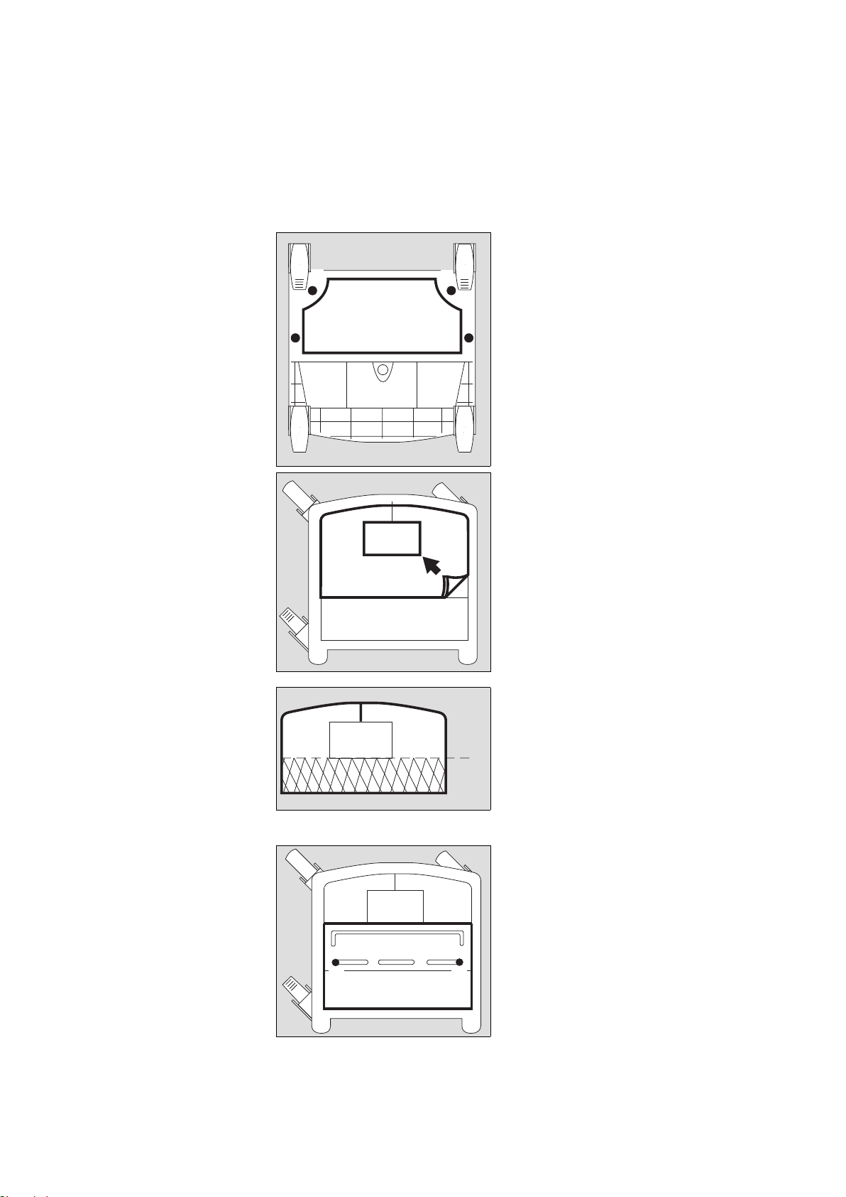
Montage sur le chariot Evita
● Déposer le respirateur du
chariot Evita.
● Coucher le chariot Evita sur le sol de
façon à ce que sa face inférieure soit
accessible.
1 Visser la tôle d’évacuation d’air sous
le cadre du chariot avec les vis cruci-
formes jointes.
● Remettre le chariot sur ses roulettes.
2 Extraire la garniture de mousse du
chariot.
● Découper la garniture de mousse le
long de la ligne de repère.
3 Remettre les deux moitiés en place
dans le chariot.
4 Dévisser les deux vis du couvercle de
la batterie, puis extraire le couvercle
de la batterie.
● Dévisser les deux vis sous le couver-
cle de la batterie.
01429080
11
1
1
01529080
2
01629080
✂
33
01729080
44
Montaje sobre el soporte
móvil Evita
● Retirar el aparato respirador del
bastidor móvil Evita.
● Tumbar en el suelo el bastidor móvil
Evita para que se pueda acceder a su
cara inferior.
1 Atornillar bajo el marco del bastidor
móvil la caperuza de escape de aire
con los tornillos de cabeza con
ranura en cruz adjuntos.
● Volver a colocar el soporte móvil
sobre sus ruedas.
2 Sacar la estera de gomaespuma del
soporte móvil.
● Cortar la estera de gomaespuma por
la línea de corte prevista.
3 Volver a colocar las dos piezas en el
bastidor móvil.
4 Desatornillar los dos tornillos de la
tapa de la batería, retirar la tapa de la
batería.
● Desatornillar los dos tornillos situa-
dos debajo de la tapa de la batería.
 Loading...