

Page 1
Page 2

Table of Contents D-Link Smart Managed Switch User Manual
Table of Contents
Table of Contents ............................................................................................................................................. i
About This Guide ............................................................................................................................................. 1
Terms/Usage .................................................................................................................................................. 1
Copyright and Trademarks ............................................................................................................................ 1
1 Product Introduction ................................................................................................................................... 2
DGS-1210-10 ................................................................................................................................................. 3
Front Panel ................................................................................................................................................. 3
Rear Panel .................................................................................................................................................. 3
DGS-1210-10P ............................................................................................................................................... 4
Front Panel ................................................................................................................................................. 4
Rear Panel .................................................................................................................................................. 5
DGS-1210-10MP ............................................................................................................................................ 5
Front Panel ................................................................................................................................................. 5
Rear Panel .................................................................................................................................................. 6
DGS-1210-20 ................................................................................................................................................. 6
Front Panel ................................................................................................................................................. 6
Rear Panel .................................................................................................................................................. 7
DGS-1210-26 ................................................................................................................................................. 7
Front Panel ................................................................................................................................................. 7
Rear Panel .................................................................................................................................................. 8
DGS-1210-28 ................................................................................................................................................. 8
Front Panel ................................................................................................................................................. 8
Rear Panel .................................................................................................................................................. 8
DGS-1210-28P ............................................................................................................................................... 9
Front Panel ................................................................................................................................................. 9
Rear Panel ................................................................................................................................................ 10
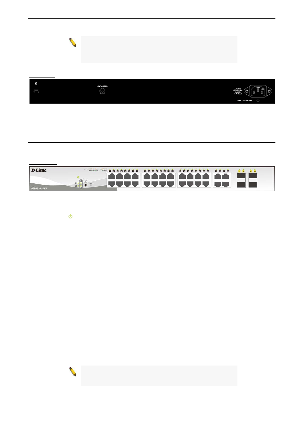
DGS-1210-28MP .......................................................................................................................................... 10
Front Panel ............................................................................................................................................... 10
Rear Panel ................................................................................................................................................ 11
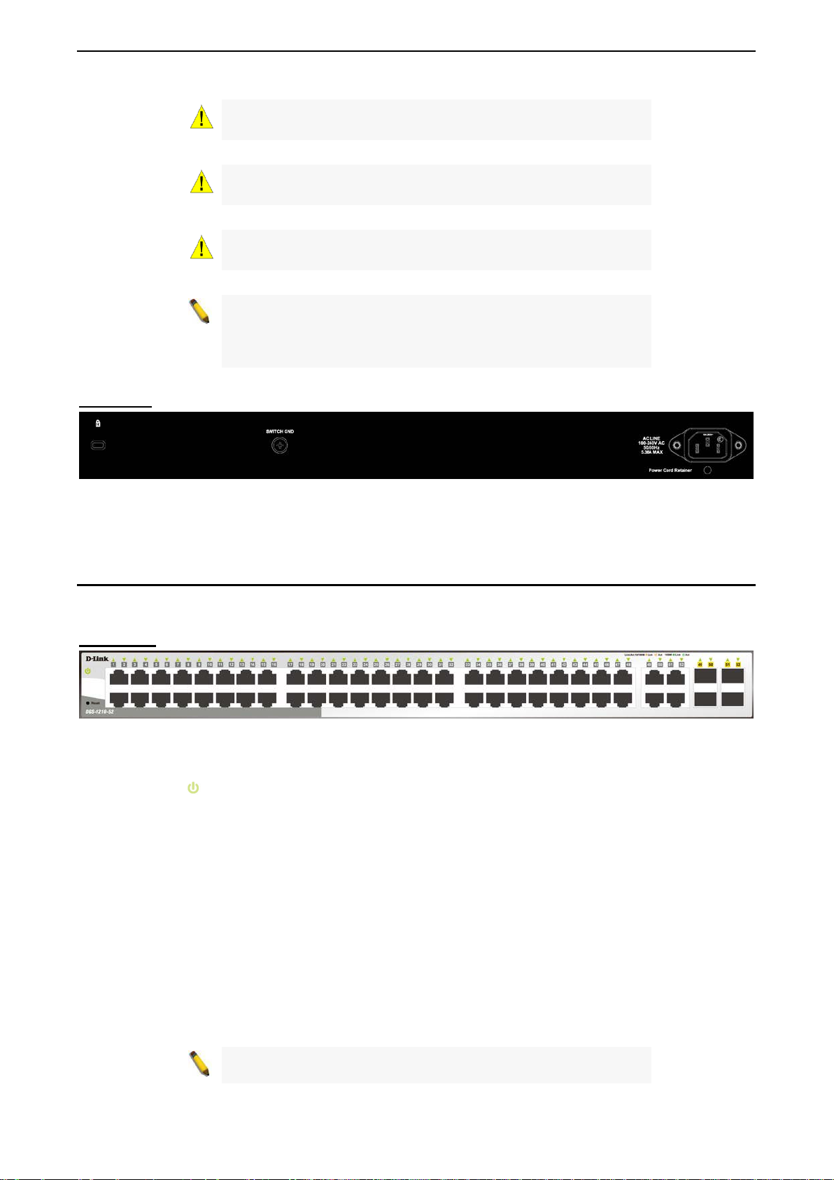
DGS-1210-52 ............................................................................................................................................... 11
Front Panel ............................................................................................................................................... 11
Rear Panel ................................................................................................................................................ 12
DGS-1210-52MP .......................................................................................................................................... 12
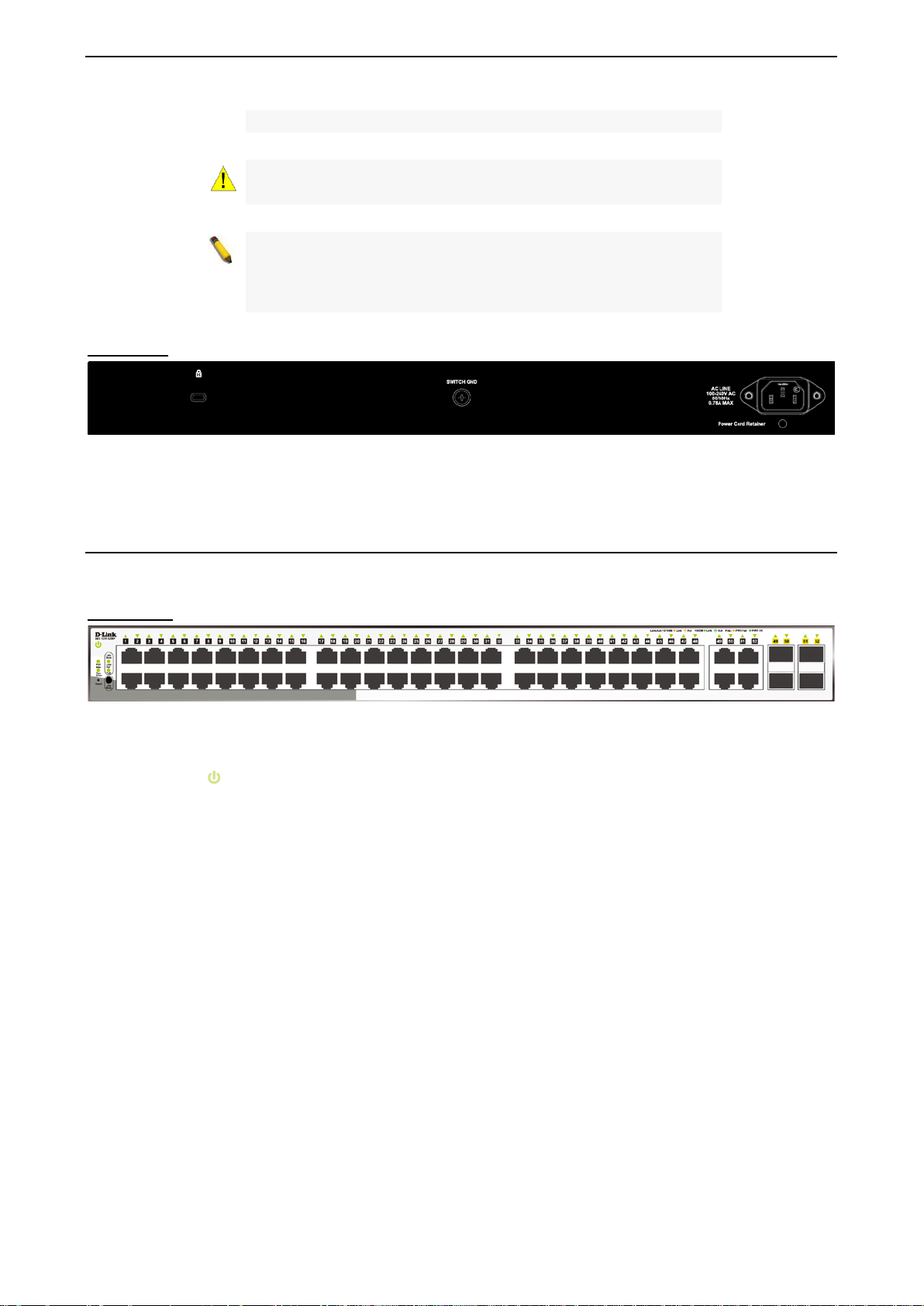
Front Panel ............................................................................................................................................... 12
Rear Panel ................................................................................................................................................ 13
LED Indicators .............................................................................................................................................. 13
2 Hardware Installation ................................................................................................................................ 15
Safety Cautions ............................................................................................................................................ 15
Step 1: Unpacking ........................................................................................................................................ 16
Step 2: Switch Installation ............................................................................................................................ 16
Desktop or Shelf Installation ..................................................................................................................... 16
Rack Installation ....................................................................................................................................... 16
Step 3: Plugging in the AC Power Cord with Power Cord Clip .................................................................... 17
Power Failure ........................................................................................................................................... 20
Grounding the Switch ............................................................................................................................... 20
3 Getting Started ........................................................................................................................................... 21
Management Options ................................................................................................................................... 21
ii
Page 3

Table of Contents D-Link Smart Managed Switch User Manual
Using Web-based Management .................................................................................................................. 21
Supported Web Browsers ........................................................................................................................ 21
Connecting to the Switch .......................................................................................................................... 21
Login Web-based Management ............................................................................................................... 21
Smart Wizard ............................................................................................................................................... 22
Web-based Management ............................................................................................................................. 22
4 Web-based Switch Configuration ............................................................................................................ 23
Smart Wizard Configuration ......................................................................................................................... 23
Step 1 – Web Mode .................................................................................................................................. 23
Step 2 – IP Information ............................................................................................................................. 24
Step 3 – Password ................................................................................................................................... 25
Step 4 – SNMP (Only for Standard Mode) ............................................................................................... 25
Web-based Management ............................................................................................................................. 27
Tool Bar > Save Menu ................................................................................................................................. 28
Save Configuration ................................................................................................................................... 28
Save Log .................................................................................................................................................. 28
Tool Bar > Tools Menu ................................................................................................................................. 28
Reset ........................................................................................................................................................ 28
Reset System ........................................................................................................................................... 28
Reboot Device .......................................................................................................................................... 29
Configuration Backup and Restore .......................................................................................................... 29
Firmware Backup and Upgrade ................................................................................................................ 30
Flash Information ...................................................................................................................................... 30
Tool Bar > Wizard ........................................................................................................................................ 30
Tool Bar > Online Help ................................................................................................................................. 31
Tool Bar > Surveillance Mode ...................................................................................................................... 31
Function Tree ............................................................................................................................................... 32
Device Information.................................................................................................................................... 32
System > System Settings ....................................................................................................................... 33
System > Password .................................................................................................................................. 34
System > Port Settings ............................................................................................................................. 35
System > Port Description ........................................................................................................................ 35
System > DHCP Auto Configuration ........................................................................................................ 36
System > DHCP Relay > DHCP Relay Global Settings ........................................................................... 36
System > DHCP Relay > DHCP Relay Interface Settings ....................................................................... 37
System > DHCP Local Relay Settings ..................................................................................................... 38
System > DHCPv6 Relay Settings ........................................................................................................... 38
System > System Log Configuration > System Log Settings .................................................................. 39
System > System Log Configuration > SysLog Host ............................................................................... 40
System > Time Profile .............................................................................................................................. 40
System > Power Saving ........................................................................................................................... 41
System > IEEE802.3az EEE Settings ...................................................................................................... 41
System > D-Link Discover Protocol Settings ............................................................................................ 42
System > Firmware Information ............................................................................................................... 43
VLAN > 802.1Q VLAN .............................................................................................................................. 43
VLAN > 802.1Q VLAN PVI D .................................................................................................................... 45
VLAN > Voice VLAN > Voic e VLAN G lob al Se t ti ngs ............................................................................... 45
VLAN > Voice VLAN > Voic e VLAN Por t Settings ................................................................................... 46
VLAN > Voice VLAN > Voice Device List ................................................................................................. 47
iiii
Page 4

Table of Contents D-Link Smart Managed Switch User Manual
VLAN > Auto Surveillance VLAN > Auto Surve illanc e Proper t ies ............................................................ 47
VLAN > Auto Surveillance VLAN > MAC Settings and Surv ei llanc e Dev ic e ........................................... 48
VLAN > Auto Surveillance VLAN > ONVIF IPC Information .................................................................... 49
VLAN > Auto Surveillance VLAN > ONVIF NVR Information................................................................... 49
L2 Functions > Jumbo Frame................................................................................................................... 50
L2 Functions > Port Mirroring ................................................................................................................... 50
L2 Functions > Loopback Detection ......................................................................................................... 50
L2 Functions > MAC Address Table > Static MAC .................................................................................. 51
L2 Functions > MAC Address Table > Dynamic Forwarding Table ......................................................... 52
L2 Functions > Spanning Tree > STP Bridge Global Settings ................................................................. 52
L2 Functions > Spanning Tree > STP Port Settings ................................................................................ 53
L2 Functions > Spanning Tree > MST Configuration Identification ......................................................... 55
L2 Functions > Spanning Tree > STP Instance Settings ......................................................................... 55
L2 Functions > Spanning Tree > MSTP Port Information ........................................................................ 56
L2 Functions > Link Aggregation > Port Trunking .................................................................................... 57
L2 Functions > Link Aggregation > LACP Port Settings .......................................................................... 57
L2 Functions > Multicast > IGMP Snooping ............................................................................................. 58
L2 Functions > Multicast > MLD Snooping .............................................................................................. 60
L2 Functions > Multicast > Multicast For war din g ..................................................................................... 61
L2 Functions > Multicast > Multicast Filtering Mode ................................................................................ 62
L2 Functions > SNTP > Time Settings ..................................................................................................... 62
L2 Functions > SNTP > TimeZone Settings ............................................................................................. 63
L2 Functions > LLDP > LLDP Global Settings ......................................................................................... 64
L2 Functions > LLDP > LLDP-MED Settings ........................................................................................... 64
L2 Functions > LLDP > LLDP Port Settings ............................................................................................. 65
L2 Functions > LLDP > 802.1 Extension TLV .......................................................................................... 66
L2 Functions > LLDP > 802.3 Extension TLV .......................................................................................... 66
L2 Functions > LLDP > LLDP Management Address Settings ................................................................ 67
L2 Functions > LLDP > LLDP Management Address Table .................................................................... 68
L2 Functions > LLDP > LLDP Local Port Table ....................................................................................... 68
L2 Functions > LLDP > LLDP Remote Port Table ................................................................................... 70
L2 Functions > LLDP > LLDP Statistics ................................................................................................... 72
L3 Functions > IP Interface ...................................................................................................................... 73
L3 Functions > IPv6 Neighbor Settings .................................................................................................... 74
L3 Functions > IPv4 Static Route ............................................................................................................. 75
L3 Functions > IPv4 Routing Table Finder ............................................................................................... 76
L3 Functions > IPv6 Static Route ............................................................................................................. 76
L3 Functions > IPv6 Routing Table Finder ............................................................................................... 77
L3 Functions > ARP > ARP Table Global Settings .................................................................................. 77
L3 Functions > ARP > Static ARP Settings .............................................................................................. 78
QoS > Bandwidth Control ......................................................................................................................... 79
QoS > 802.1p/DSCP/ToS ......................................................................................................................... 79
Security > Trusted Host ............................................................................................................................ 80
Security > Port Security ............................................................................................................................ 81
Security > Traffic Segmentation ............................................................................................................... 81
Security > Safeguard Engine.................................................................................................................... 82
Security > Storm Control .......................................................................................................................... 82
Security > ARP Spoofing Prevention ....................................................................................................... 83
Security > DHCP Server Screening ......................................................................................................... 84
iii
Page 5

Table of Contents D-Link Smart Managed Switch User Manual
Security > SSL .......................................................................................................................................... 84
Security > DoS Prevention Settings ......................................................................................................... 86
Security > SSH > SSH Settings ............................................................................................................... 86
Security > SSH > SSH Authmode and Algorithm Settings....................................................................... 87
Security > SSH > SSH User Authentication Lists .................................................................................... 88
Security > Smart Binding > Smart Binding Settings ................................................................................. 88
Security > Smart Binding > Smart Binding ............................................................................................... 89
Security > Smart Binding > White List ...................................................................................................... 90
Security > Smart Binding > Black List ...................................................................................................... 90
AAA > RADIUS Server ............................................................................................................................. 91
AAA > 802.1X > 802.1X Global Settings .................................................................................................. 91
AAA > 802.1X > 802.1X Port Settings...................................................................................................... 92
AAA > 802.1X > 802.1X User ................................................................................................................... 93
ACL > ACL Wizard ................................................................................................................................... 93
ACL > ACL Access List .......................................................................................................................... 107
ACL > ACL Access Group ...................................................................................................................... 108
ACL > ACL Hardware Resource Status ................................................................................................. 109
PoE > PoE Global Settings (only for DGS-1210-10P/10MP/28P/28MP/52MP) .................................... 109
PoE > PoE Port Settings (only for DGS-1210-10P/10MP/28P/28MP/52MP) ........................................ 110
SNMP > SNMP > SNMP Global Settings .............................................................................................. 112
SNMP > SNMP > SNMP User ............................................................................................................... 113
SNMP > SNMP > SNMP Group Table ................................................................................................... 113
SNMP > SNMP > SNMP View ............................................................................................................... 114
SNMP > SNMP > SNMP Community ..................................................................................................... 114
SNMP > SNMP > SNMP Host ................................................................................................................ 115
SNMP > SNMP > SNMP Engine ID ....................................................................................................... 115
SNMP > RMON > RMON Global Settings ............................................................................................. 115
SNMP > RMON > RMON Statistics ....................................................................................................... 116
SNMP > RMON > RMON History ........................................................................................................... 116
SNMP > RMON > RMON Alarm ............................................................................................................ 116
SNMP > RMON > RMON Event ............................................................................................................. 117
Monitoring > Port Statistics ..................................................................................................................... 118
Monitoring > Cable Diagnostics ............................................................................................................. 118
Monitoring > System Log ........................................................................................................................ 119
5 Surveillance Mode Configuration ........................................................................................................... 121
Web User Interface .................................................................................................................................... 121
Surveillance Overview ................................................................................................................................ 122
Surveillance Topology ............................................................................................................................ 123
Device Information.................................................................................................................................. 124
Port Information ...................................................................................................................................... 125
IP-Camera Information ........................................................................................................................... 125
NVR Information ..................................................................................................................................... 125
PoE Information ...................................................................................................................................... 126
PoE Scheduling ...................................................................................................................................... 126
Time > Clock Settings ............................................................................................................................ 127
Time > SNTP Settings ............................................................................................................................ 127
Surveillance Settings .............................................................................................................................. 128
Surveillance Log ..................................................................................................................................... 130
Health Diagnostic ................................................................................................................................... 130
iivv
Page 6

Table of Contents D-Link Smart Managed Switch User Manual
Tool Bar > Wizard ...................................................................................................................................... 131
Tool Bar > Tools Menu ............................................................................................................................... 131
Reset System ......................................................................................................................................... 131
Reboot Device ........................................................................................................................................ 132
Configuration Backup & Restore ............................................................................................................ 132
Firmware Backup and Upgrade .............................................................................................................. 133
Firmware Information.............................................................................................................................. 133
Flash Information .................................................................................................................................... 134
Tool Bar > Save ......................................................................................................................................... 134
Tool Bar > Help .......................................................................................................................................... 134
Tool Bar > Online Help ............................................................................................................................... 135
Tool Bar > Standard Mode ......................................................................................................................... 135
6 Command Line Interface ......................................................................................................................... 136
To connect a switch via TELNET: .............................................................................................................. 136
Logging on to the Command Line Interface: .............................................................................................. 136
CLI Commands: ......................................................................................................................................... 136
? .............................................................................................................................................................. 137
download ................................................................................................................................................ 138
upload ..................................................................................................................................................... 139
config firmware image_id ....................................................................................................................... 140
config ipif system .................................................................................................................................... 140
config ipif system .................................................................................................................................... 141
logout ...................................................................................................................................................... 141
ping ......................................................................................................................................................... 142
ping6 ....................................................................................................................................................... 142
reboot ..................................................................................................................................................... 143
reset config ............................................................................................................................................. 143
show boot_file ......................................................................................................................................... 143
show firmware information ..................................................................................................................... 144
show flash information ............................................................................................................................ 145
show ipif .................................................................................................................................................. 145
show switch ............................................................................................................................................ 146
show route .............................................................................................................................................. 146
config account admin password ............................................................................................................. 147
save ........................................................................................................................................................ 147
debug info ............................................................................................................................................... 147
Appendix A - Ethernet Technology ............................................................................................................ 149
Gigabit Ethernet Technology ..................................................................................................................... 149
Fast Ethernet Technology .......................................................................................................................... 149
Switching Technology ................................................................................................................................ 149
Appendix B - Technical Specifications ..................................................................................................... 150
Hardware Specifications ............................................................................................................................ 150
Features ..................................................................................................................................................... 154
L2 Features ............................................................................................................................................ 154
L3 Features ............................................................................................................................................ 154
VLAN ...................................................................................................................................................... 154
QoS (Quality of Service) ......................................................................................................................... 154
Security ................................................................................................................................................... 154
OAM ....................................................................................................................................................... 155
v
Page 7

Table of Contents D-Link Smart Managed Switch User Manual
Management ........................................................................................................................................... 155
D-Link Green Technology ...................................................................................................................... 155
Appendix C – Rack mount Instructions .................................................................................................... 156
Regulatory Information ............................................................................................................................... 157
Federal Communication Commission Interference Statement .................................................................. 157
Japan Voluntary Control Council for Interference Statement .................................................................... 157
Japan Voluntary Control Council for Interference Statement .................................................................... 157
警告使用者: ................................................................................................................................................ 157
CE EMI Class A Warning ........................................................................................................................... 157
SAFETY INSTRUCTIONS ......................................................................................................................... 157
SICHERHEITSVORSCHRIFTEN .............................................................................................................. 157
CONSIGNES DE SÉCURITÉ .................................................................................................................... 158
INSTRUCCIONES DE SEGURIDAD ......................................................................................................... 158
ISTRUZIONI PER LA SICUREZZA ........................................................................................................... 158
VEILIGHEIDSINFORMATIE ...................................................................................................................... 159
Disposing of and Recycling Your Product.................................................................................................. 159
vvii
Page 8

About This Guide D-Link Smart Managed Switch User Manual
l you have purchased may
detailed information about your switch, its
information that
About This Guide
This guide provides instructions to install the D-Link Smart Managed Switch DGS-1210 series, and to
configure Web-based Management step-by-step.
Note: The mode
appear slightly different from the illustrations
shown in the document. Refer to the Product
Instruction and Technical Specification sections
for
components, network connections, and technica l
specifications.
This guide is mainly divided into four parts:
1. Hardware Installation: Ste p -by-step hardware installation procedures.
2. Getting Started: A startup guide for basic switch installation and settings.
3. Web Configuration: Information about the function descriptions and configuration settings via Web.
4. Command Line Interf ace: Information about the functi on descriptions and configuratio n settings via
Telnet.
Terms/Usage
In this guide, the term “Switch” (first letter capitalized) ref ers to the Smart Switch, and “switch” (first letter
lower case) refers to other Ethernet switches. Some technologies refer to terms “switch”, “bridge” and
“switching hubs” interchangeably, and both are commonly accepted for Ethernet switches.
A NOTE indicates important
helps a better use of the device.
A CAUTION indicates pote ntial prop erty dam age
or personal injury.
Copyright and Trademarks
Information in this document is subjected to change without notice.
© 2017 D-Link Corporation. All rights reserved.
Reproduction in any manner whatsoever without the written permission of D-Link Corporation is strictly
forbidden.
Trademarks used in th is text: D-Link and the D-LIN K logo are trademarks of D-Link Corporation; Micros oft
and Windows are registered trademarks of Microsoft Corporation.
Other trademarks and trade names ma y be used in this document to refer to either the entities cla iming the
marks and names or their product s. D-Link C orporation disclaim s any proprietar y interest in tr ademarks and
trade names other than its own.
1
Page 9

1 Product Introduction D-Link Smart Managed Switch User Manual
1 Product Introduction
Thank you and congratulations on your purchase of D-Link Smart Managed Switch Products.
D-Link's next generation S mart Managed switch serie s blends p lug-and-play simplic ity with exceptiona l valu e
and reliability for small an d m edium-sized business ( SMB) net work ing. All m odels are housed in a n ew st yle
rack-mount metal case with easy-to-view front panel diagnostic LEDs, and provides advanced features
including network security, traffic segmentation, QoS and versatile management.
Flexible Port Configurations. The DGS-1210 series is the new generation of Smart Managed Switch series.
It provides 8, 16, 24 or 48 10/100/1000Mbps Non-PoE or PoE ports plus 4 GE/SFP ports. All switches o f th e
DGS-1210 series feature e mbedded 4 gigab it SFP uplink s, which pro vides flexibl e network topol ogy choices
such as ring, tree, or mixed.
D-Link Green Technology. D-Link Green devices are about providing eco-friendly alternatives without
compromising perf ormance. D-Link Green T echnology includes a number of inn ovations to reduce energy
consumption on DGS-1210 series such as shutting down a port, or turning off some LED indicators, or
adjusting the power usage according to the Ethernet cable connected to it.
Extensive Layer 2 Featu res. Im plemented as complete L2 devices, these switc hes include functions such
as IGMP snooping, port mirroring, Spanning Tree, 802.3ad LACP and Loopback Detection to enhance
performance and network resiliency.
Traffic Segmentation, QoS and Auto Surveillance VLAN. The switches support 802.1Q VLAN standard
tagging t o enhance network secur ity and performance. The switches also support 802.1p priority queues,
enabling users to run bandwidth-sensitive applications such as streaming multimedia by prioritizing that
traffic in network. These functions allow switches to work seamlessly with VLAN and 802.1p traffic in the
network. Aut o Surveillance VLAN will autom atically place the vedio traffic from pre-defined IP surveillance
devices to an assigned VLAN with higher priority, so it can be separated from normal data traffic. Asymmetric
VLAN is implemented in these switches for a more efficient use of shared resources, such as server or
gateway devices.
Network Security. D-Link’s innovative Safeguard Engine function protects the switches against traffic
flooding caus ed by virus attacks. Addition al features like 802.1X por t-based authentication provide access
control of the networ k with external RADIUS servers. ACL is a po werful tool to screen u nwanted IP or MAC
traffic. Storm Control can help to keep the network from being overwhelmed by abnormal traffic. Port
Security is another simple but useful authentication method to maintain the network device integrity.
Versatile Management. The new generation of D-Link Smart Managed Switches provides growing
businesses simple and easy management of their network. The multi-l ang uag e Web-Based management
interface allows administrators to remotely control their network down to the port level. The intuitive easily
allows customers to discover multiple D-Link Smart Managed Switches in the same L2 network segment.
With this utility, users do not need to change the IP address of PC and provides easy initial setting of smart
switches. The switches within the same L2 network segment connected to user’s local PC are displayed on
the screen for instant access. It allows extensive switch configuration setting, and basic configuration of
discovered devices such as a password change or firmware upgrade.
Users can also access the Switch via Telnet. Basic tasks such as changing the Switch IP address, resetting
the settings to factory defaults, setting the administrator password, rebooting the Switch, or upgrading the
Switch firmware can be performed using the Command Line Interface (CLI)
In addition, users can utilize the SNMP MIB (Management Information Base) to poll the switches for
information about the status, or send out traps of abnorm al events. SNMP supp ort allows users to int egrate
2
Page 10
1 Product Introduction D-Link Smart Managed Switch User Manual
listed Optical
(standalone version 2.0.2.4 only (No support by Chrome
Link Technical
the switches with other thir d-part y devices for managem ent in an SNMP-enabl ed environment. D-Link Smart
Managed Switches provides easy-to-use graphic interface and facilitates the operation efficiency.
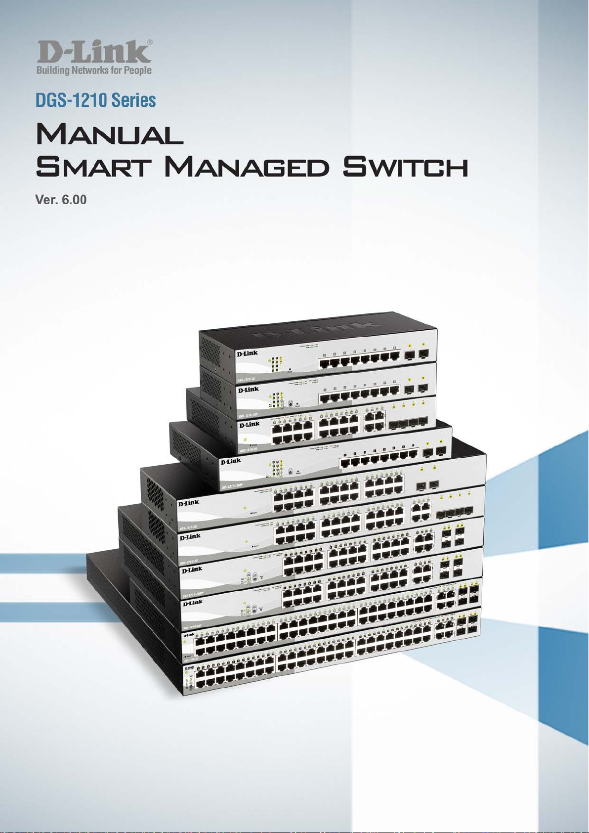
DGS-1210-10
8-Port 10/100/1000Mbps plus 2 SFP ports (100/1000Mbps) Smart Managed Switch.
Front Panel
Figure 1.1 – DGS-1210-10 Front Panel
The front panel of the DGS-1210-10 switch consists out of the following:
• Power LED
• Port Link/Act/Speed LED (1-8): The Link/Act/Speed LED flashes, which indicates a network link
through the correspond ing port. Blink ing indicates that the Switch is either s ending or r eceiving data to
the port. W hen a port has an am ber light, this indicates that the port is running on 10M or 100M. W hen
it has a green light it is running on 1000M.
• Port Link/Act/Speed LED (9F, 10F): T he Link/Act/Speed LED flashes, which indicates a networ k link
through the correspond ing port. Blink ing indicates that the Switch is either s ending or r eceiving data to
the port. When the por t LED glows in amber, it indicates the port is runnin g on 100M. When the port
LED glows in green, it is running on 1000Mbps.
• Reset: Press the Reset bu tton for 1~5 seconds to reboot the device. Press the Reset butt on for 6~10
seconds to reset the Switch back to the default settings and led will be solid light with amber for 2
seconds. Or press the Reset button over 11 seconds to enter the loader m ode after device reboot and
the led will be so lid light with green f or 2 seconds. If the device canno t reboot the Switch via image 1
and image 2, the device will enter the loader mode automatically.
: The Power LED lights up when the Switch is connected to a power source.
CAUTION: The MiniGBIC ports should use UL
Transceiver product, Rated Laser Class I. 3.3Vdc.
NOTE: Once user enter in loader mode, you can use DNA tool
DNA3.x.x.x)) to download the image or call D-
Support for further help.
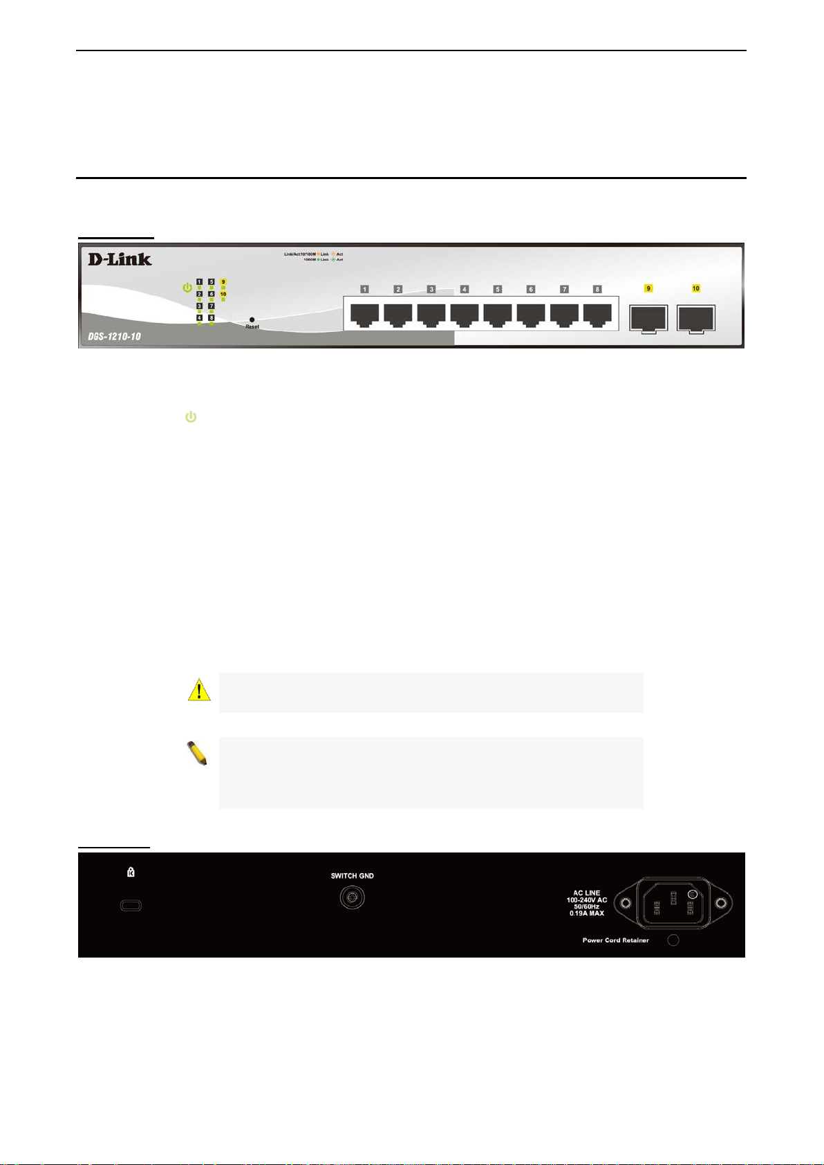
Rear Panel
Figure 1.2 – DGS-1210-10 Rear Panel
Power: Connect the supplied AC power cable to this port.
33
Page 11
1 Product Introduction D-Link Smart Managed Switch User Manual
listed Optical
nnected only to PoE
(standalone version 2.0.2.4 only (No support by Chrome
Link Technical
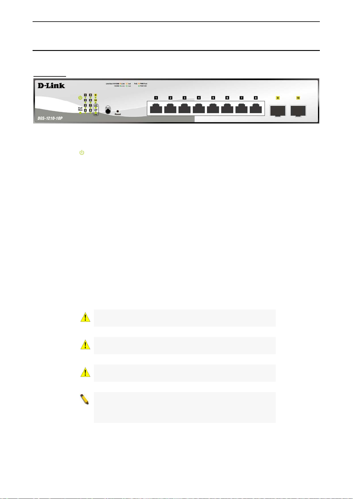
DGS-1210-10P
8-Port 10/100/1000Mbps plus 2 SFP Ports (100/1000Mbps) Smart Managed PoE Switch.
Front Panel
Figure 1.3 – DGS-1210-10P Front Panel
The front panel of the DGS-1210-10P switch consists out of the following:
• Power LED
• PoE Max: The PoE Max LED lights up with solid red when the Switch reaches the m aximum power
budget define d by the administrator v ia PoE System Settings pag e of Web GUI or the default power
budget of 65 Watts.
• Port Link/Act/Speed LED (1-8): The Link/Act/Speed LED flashes, which indicates a network link
through the correspond ing port. Blink ing indicates that the Switch is either sending or r eceiving data to
the port. When a port has an am ber light, this in dicates t hat the port is running on 10M or 100M . When
it has a green light it is running on 1000M.
• Port Link/Act/Speed LED (9F, 10F): T he Link/Act/Speed LED flashes, which i ndicates a network link
through the correspond ing port. Blink ing indicates that the Switch is either s ending or r eceiving data to
the port. When the por t LED glows in amber, it indicates the port is running on 100M. When the port
LED glows in green, it is running on 1000Mbps.
• LED Mode: To select the m ode of port LED, the Link/Ac t and PoE LED under the mode b utton will
solid green to indicate which mode is selected.
• Mode: By pressing the Mode button, the Port LED will switch between Link/Act and PoE modes.
• Reset: Press the Reset bu tton for 1~5 seconds to re boot the dev ice. Press the Reset button f or 6~10
seconds to reset the Switch back to the default settings and led will be solid light with amber for 2
seconds. Or press the Reset button o ver 11 seconds to enter the loader mode after de vice reboot and
the led will be so lid light with green f or 2 seconds. If the device canno t reboot the Switch via image 1
and image 2, the device will enter the loader mode automatically.
: The Power LED lights up when the Switch is connected to a power source.
CAUTION: The MiniGBIC ports should use UL
Transceiver product, Rated Laser Class I. 3.3Vdc.
CAUTION: The port 1 ~ por t 8 are PoE ports. When user press the
Mode button to PoE mode, only port 1 ~ port 8 will light up.
CAUTION: This equipment can be co
networks without routing to the outside plant.
NOTE: Once user enter in loader mode, you can use DNA tool
DNA3.x.x.x)) to download the image or call D-
Support for further help.
4
Page 12
1 Product Introduction D-Link Smart Managed Switch User Manual
listed Optical
be connected only to PoE
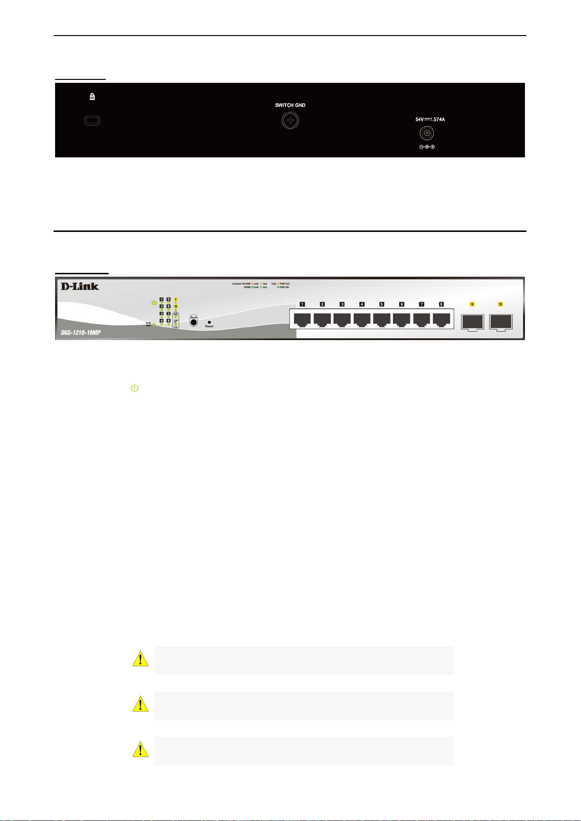
Rear Panel
Figure 1.4 – DGS-1210-10P Rear Pan el
Power: Connect the supplied DC external power 54V/1.574A cable to this port.
DGS-1210-10MP
8-Port 10/100/1000Mbps plus 2 SFP Ports (100/1000Mbps) Smart Managed PoE Switch.
Front Panel
Figure 1.5 – DGS-1210-10MP Front Panel
The front panel of the DGS-1210-10MP switch consists out of the following:
• Power LED
: The Power LED lights up when the Switch is connected to a power source.
• PoE Max: The PoE Max LED lights up with solid red when the Switch reaches the m aximum power
budget define d by the administrator v ia PoE System Settings pag e of Web GUI or the default power
budget of 130 Watts.
• Port Link/Act/Speed LED (1-8): The Link/Act/Speed LED flashes, which indicates a network link
through the corresponding port. Blink ing indicates th at the Switch is e ither sending or receiving data to
the port. When a port has an am ber light, this in dicates t hat the port is running on 10M or 100M . When
it has a green light it is running on 1000M.
• Port Link/Act/Speed LED (9F, 10F): T he Link/Act/Speed LED flashes, which indicates a networ k link
through the correspond ing port. Blink ing indicates that the Switch is either s ending or r eceiving data to
the port. When the por t LED glows in amber, it indicates the port is running on 100M. When the port
LED glows in green, it is running on 1000Mbps.
• LED Mode: To select the m ode of port LED, the Link/Ac t and PoE LED under the mode b utton will
solid green to indicate which mode is selected.
• Mode: By pressing the Mode button, the Port LED will switch between Link/Act and PoE modes.
• Reset: Press the Reset bu tton for 1~5 seconds to re boot the dev ice. Press the Reset button f or 6~10
seconds to reset the Switch back to the default settings and led will be solid light with amber for 2
seconds. Or press the Reset button over 11 seconds to enter the loader m ode after de vice reboot and
the led will be so lid light with green f or 2 seconds. If the device canno t reboot the Switch via image 1
and image 2, the device will enter the loader mode automatically.
CAUTION: The MiniGBIC ports should use UL
Transceiver product, Rated Laser Class I. 3.3Vdc.
CAUTION: The port 1 ~ por t 8 are PoE ports. When user press the
Mode button to PoE mode, only port 1 ~ port 8 will light up.
CAUTION: This equipment can
networks without routing to the outside plant.
55
Page 13
1 Product Introduction D-Link Smart Managed Switch User Manual
(standalone version 2.0.2.4 only (No support by Chrome
Link Technical
listed Optical
NOTE: Once user enter in loader mode, you can use DNA tool
DNA3.x.x.x)) to download the image or call D-
Support for further help.
Rear Panel
Figure 1.6 – DGS-1210-10MP Rear Panel
Power: Connect the supplied AC power cable to this port.
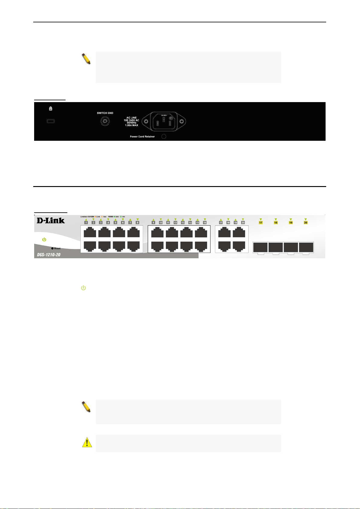
DGS-1210-20
16-Port 10/100/1000Mbps plus 4 Combo GE/SFP Slot Smart Managed Switch.
Front Panel
Figure 1.7 – DGS-1210-20 Front Panel
The front panel of the DGS-1210-20 switch consists out of the following:
• Power LED
: The Power LED lights up when the Switch is connected to a power source.
• Port Link/Act/Speed LED (1-16): The Link/Act/Speed LED flashes, which indicates a network link
through the correspond ing port. Blink ing indicates that the Switch is either s ending or r eceiving data to
the port. When a port has an am ber light, this in dicates t hat the port is running on 10M or 100M . When
it has a green light it is running on 1000M.
• Port Link/Act/Speed LED (17F, 18F, 19F, 20F, 17T, 18T, 19T , 20T): The Link/Act/Speed LED flashes,
which indicates a network link through the corresponding port. Blinking indicates that the Switch is
either sending or receiv ing data to the port. When the port LED glows in amber, it indicates the port is
running on 100M. When the port LED glows in green, it is running on 1000Mbps.
• Reset: Press the Reset bu tton for 1~5 seconds to re boot the device. Press the Res et button for 6~10
seconds to reset the Switch back to the default settings and led will be solid light with amber for 2
seconds. Or press the Reset button over 11 seconds to enter the loader m ode after de vice reboot and
the led will be so lid light with green f or 2 seconds. If the device canno t reboot the Switch via image 1
and image 2, the device will enter the loader mode automatically.
NOTE: On the DGS-1210-20, the M iniGBIC ports are shared with
normal RJ-45 ports 17T, 18T, 19T and 20T. When the MiniGBIC
port is used, the RJ-45 port cannot be used.
CAUTION: The MiniGBIC ports should use UL
Transceiver product, Rated Laser Class I. 3.3Vdc.
6
Page 14
1 Product Introduction D-Link Smart Managed Switch User Manual
support by Chrome
Link Technical
listed Optical
(standalone version 2.0.2.4 only (No support by Chrome
Link Technical
NOTE: Once user enter in loader mode, you can use DNA tool
(standalone version 2.0.2.4 only (No
DNA3.x.x.x)) to download the image or call DSupport for further help.
Rear Panel
Figure 1.8 – DGS-1210-20 Rear Panel
Power: Connect the supplied AC power cable to this port.
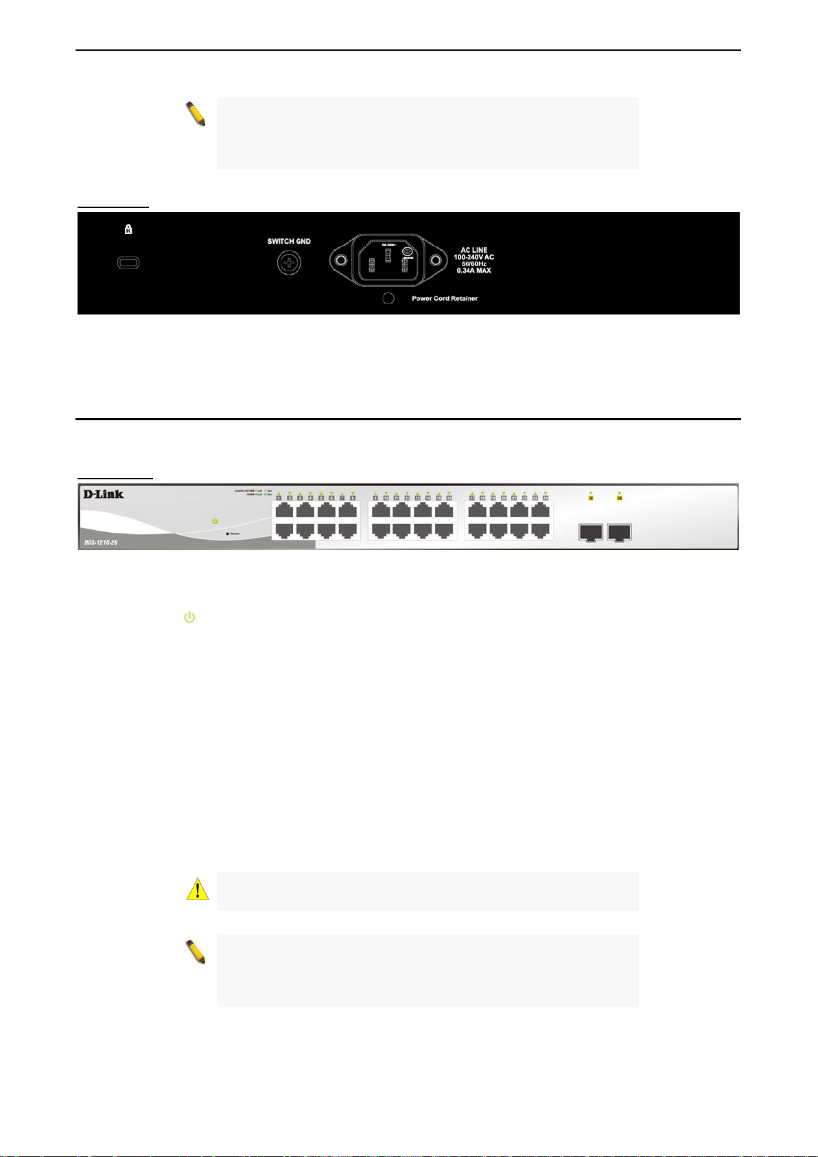
DGS-1210-26
24-Port 10/100/1000Mbps plus 2 SFP Ports (100/1000Mbps) Smart Managed Switch.
Front Panel
Figure 1.9 – DGS-1210-26 Front Panel
The front panel of the DGS-1210-26 switch consists out of the following:
• Power LED
: The Power LED lights up when the Switch is connected to a power source.
• Port Link/Act/Speed LED (1-24): The Link/Act/Speed LED flashes, which indicates a network link
through the correspond ing port. Blink ing indicates that the Switch is either s ending or r eceiving data to
the port. When a port has an am ber light, this indicates that the port is running on 10M or 100M. W hen
it has a green light it is running on 1000M.
• Port Link/Act/Speed LED (25F, 26F): The Link/Act/Speed LED f lashes, which indicates a net work li nk
through the correspond ing port. Blink ing indicates that the Switch is either sending or receiving data to
the port. When the por t LED glows in amber, it indicates the port is runnin g on 100M. When the port
LED glows in green, it is running on 1000Mbps.
• Reset: Press the Reset bu tton for 1~5 seconds to re boot the dev ice. Press the Reset button f or 6~10
seconds to reset the Switch back to the default settings and led will be solid light with amber for 2
seconds. Or press the Reset button over 11 seconds to enter the loader m ode after de vice reboot and
the led will be so lid light with green f or 2 seconds. If the device canno t reboot the Switch via image 1
and image 2, the device will enter the loader mode automatically.
CAUTION: The MiniGBIC ports should use UL
Transceiver product, Rated Laser Class I. 3.3Vdc.
NOTE: Once user enter in loader mode, you can use DNA tool
DNA3.x.x.x)) to download the image or call D-
Support for further help.
77
Page 15
1 Product Introduction D-Link Smart Managed Switch User Manual
(standalone version 2.0.2.4 only (No support by Chrome
Link Technical
Rear Panel
Figure 1.10 – DGS-1210-26 Rear Panel
Power: Connect the supplied AC power cable to this port.
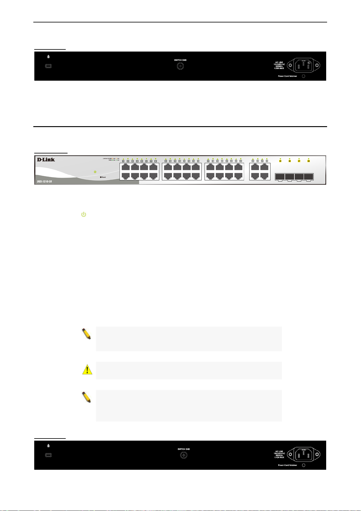
DGS-1210-28
24-Port 10/100/1000Mbps plus 4 Combo GE/SFP Slot Smart Managed Switch.
Front Panel
Figure 1.11 – DGS-1210-28 Front Panel
The front panel of the DGS-1210-28 switch consists out of the following:
• Power LED
• Port Link/Act/Speed LED (1-24): The Link/Act/Speed LED flashes, which indicates a network link
through the correspond ing port. Blink ing indicates that the Switch is either sending or r eceiving data to
the port. When a port has an am ber light, this in dicates t hat the port is running on 10M or 100M . When
it has a green light it is running on 1000M.
• Port Link/Act/Speed L ED (25F, 26F, 27F , 28F , 25T , 26T, 27T , 28T ): The Link/Act/Speed LED flashes,
which indicates a network link through the corresponding port. Blinking indicates that the Switch is
either sending or receiv ing data to the port. When the port LED glows in amber, it indicates the port is
running on 100M. When the port LED glows in green, it is running on 1000Mbps .
• Reset: Press the Reset bu tton for 1~5 seconds to re boot the dev ice. Press the Reset button f or 6~10
seconds to reset the Switch back to the default settings and led will be solid light with amber for 2
seconds. Or press the Reset button over 11 seconds to enter the loader m ode after de vice reboot and
the led will be so lid light with green f or 2 seconds. If the device canno t reboot the Switch via image 1
and image 2, the device will enter the loader mode automatically.
: The Power LED lights up when the Switch is connected to a power source.
NOTE: On the DGS-1210-28, the M iniGBIC ports are shared with
normal RJ-45 ports 25T , 26T, 27T and 28T. When the MiniGBIC
port is used, the RJ-45 port cannot be used.
CAUTION: The MiniGBIC ports should use UL listed Optical
Transceiver product, Rated Laser Class I. 3.3Vdc.
NOTE: Once user enter in loader mode, you can use DNA tool
DNA3.x.x.x)) to download the image or call D-
Support for further help.
Rear Panel
8
Page 16
1 Product Introduction D-Link Smart Managed Switch User Manual
listed Optical
be connected only to PoE
Figure 1.12 – DGS-1210-28 Rear Pane l
Power: Connect the supplied AC power cable to this port.
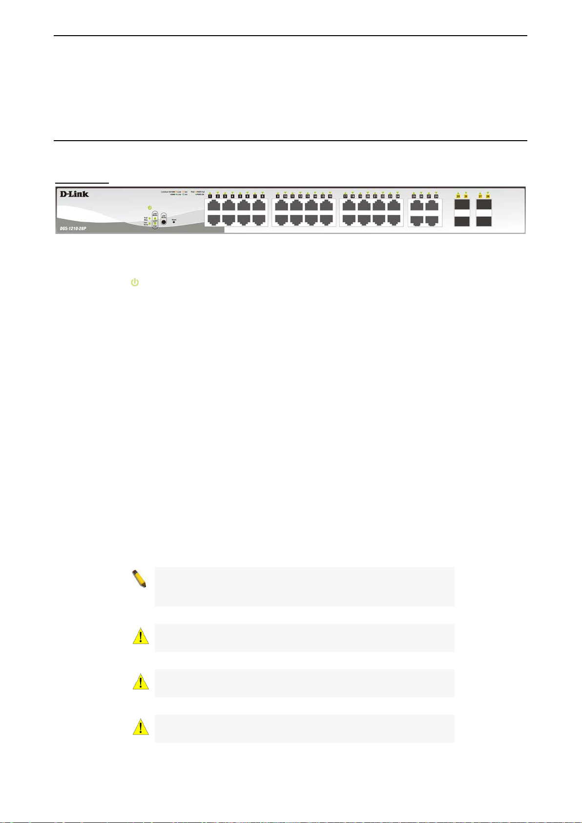
DGS-1210-28P
24-Port 10/100/1000Mbps plus 4 Combo GE/SFP Smart Manag ed Po E Switch.
Front Panel
Figure 1.13 – DGS-1210-28P Front Panel
The front panel of the DGS-1210-28P switch consists out of the following:
• Power LED
• Fan Error: The FAN LED shows the status of the f ans, ligh t off indicates all fans work fine and th e red
light indicates that one or multiple fans are working abnormally.
• PoE Max: The PoE Max LED lights up with solid red when the Switch reaches the m aximum power
budget define d by the administrator v ia PoE System Settings pag e of Web GUI or the default power
budget of 193 Watts.
• LED Mode: To select the m ode of port LED, the Link/Ac t and PoE LED under the mode b utton will
solid green to indicate which mode is selected.
• Port Link/Act/Speed LED (1-24): The Link/Act/Speed LED flashes, which indicates a network link
through the correspond ing port. Blink ing indicates that the Switch is either s ending or r eceiving data to
the port. When a port has an am ber light, this in dicates t hat the port is running on 10M or 100M . When
it has a green light it is running on 1000M.
• Port Link/Act/Speed L ED (25F, 26F, 27F , 28F , 25T , 26T, 27T , 28T ): The Link/Act/Speed LED flashes,
which indicates a network link through the corresponding port. Blinking indicates that the Switch is
either sending or receiv ing data to the port. When the port LED glows in amber, it indicates the port is
running on 100M. When the port LED glows in green, it is running on 1000Mbps.
• Reset: Press the Reset bu tton for 1~5 seconds to re boot the dev ice. Press the Reset button f or 6~10
seconds to reset the Switch back to the default settings and led will be solid light with amber for 2
seconds. Or press the Reset button over 11 seconds to enter the loader m ode after de vice reboot and
the led will be so lid light with green f or 2 seconds. If the device canno t reboot the Switc h via image 1
and image 2, the device will enter the loader mode automatically.
• LED Mode: By pressing the Mode button, the Port LED will switch between Link/Act and PoE modes.
: The Power LED lights up when the Switch is connected to a power source.
NOTE: On the DGS-1210-28P, the MiniGBIC ports are shared with
normal RJ-45 ports 25T, 26T , 27T and 28T. When the MiniGBIC
port is used, the RJ-45 port cannot be used.
CAUTION: The MiniGBIC ports should use UL
Transceiver product, Rated Laser Class I. 3.3Vdc.
CAUTION: The port 1 ~ p ort 24 ar e PoE ports. When user press
the Mode button to PoE mode, only port 1 ~ port 24 will light up.
CAUTION: This equipment can
networks without routing to the outside plant.
99
Page 17
1 Product Introduction D-Link Smart Managed Switch User Manual
ndalone version 2.0.2.4 only (No support by Chrome
Link Technical
NOTE: Once user enter in loader mode, you can use DNA tool
(sta
DNA3.x.x.x)) to download the image or call DSupport for further help.
Rear Panel
Figure 1.14 – DGS-1210-28P Rear Panel
Power: Connect the supplied AC power cable to this port.
DGS-1210-28MP
24-Port 10/100/1000Mbps plus 4 combo GE/SFP Slot Smar t Managed PoE Switch.
Front Panel
Figure 1.15 – DGS-1210-28MP Front Panel
The front panel of the DGS-1210-28MP switch consists out of the following:
• Power LED
: The Power LED lights up when the Switch is connected to a power source.
• Fan Error: The FAN LED shows the status of the f ans, ligh t off indicates all fans work fine and th e red
light indicates that one or multiple fans are working abnormally.
• PoE Max: The PoE Max LED lights up with solid red when the Switch r eaches the maximum power
budget define d by the administrator v ia PoE System Settings pag e of Web GUI or the default power
budget of 370 Watts.
• LED Mode: To select the mode of port LED, the Link /Act and PoE LED under the m ode button will
solid green to indicate which mode is selected.
• Port Link/Act/Speed LED (1-24): The Link/Act/Speed LED flashes, which indicates a network link
through the correspond ing port. Blink ing indicates that the Switch is either s ending or r eceiving data to
the port. W hen a port has an am ber light, this indicates that the port is running on 10M or 100M. W hen
it has a green light it is running on 1000M.
• Port Link/Act/Speed L ED (25F, 26F, 27F , 28F , 25T , 26T, 27T , 28T ): The Link/Act/Speed LED flashes,
which indicates a network link through the corresponding port. Blinking indicates that the Switch is
either sending or receiv ing data to the port. When the port LED glows in amber, it indicates the port is
running on 100M. When the port LED glows in green, it is running on 1000Mbps.
• Reset: Press the Reset bu tton for 1~5 seconds to reboot the dev ice. Press the Reset button f or 6~10
seconds to reset the Switch back to the default settings and led will be solid light with amber for 2
seconds. Or press the Reset button over 11 seconds to enter the loa der mode after device reboot and
the led will be solid l ight with green for 2 seconds. If the device cannot reboot the Switch via im age 1
and image 2, the device will enter the loader mode automatically.
• LED Mode: By pressing the Mode button, the Port LED will switch between Link/Act and PoE modes.
NOTE: On the DGS-1210-28MP, the MiniGBIC ports are shared
with normal RJ-45 ports 25T, 26T, 27T and 28T. When the
MiniGBIC port is used, the RJ-45 port cannot be used.
10
Page 18
1 Product Introduction D-Link Smart Managed Switch User Manual
listed Optical
be connected only to PoE
(standalone version 2.0.2.4 only (No support by Chrome
Link Technical
normal RJ-45 ports 49T, 50T, 51T and 52T. When the MiniGBIC
CAUTION: The MiniGBIC ports should use UL
Transceiver product, Rated Laser Class I. 3.3Vdc.
CAUTION: The port 1 ~ p ort 24 ar e PoE ports. When user pr ess
the Mode button to PoE mode, only port 1 ~ port 24 will light up.
CAUTION: This equipment can
networks without routing to the outside plant.
NOTE: Once user enter in loader mode, you can use DNA tool
DNA3.x.x.x)) to download the image or call D-
Support for further help.
Rear Panel
Figure 1.16 – DGS-1210-28MP Rear Panel
Power: Connect the supplied AC power cable to this port.
DGS-1210-52
48-Port 10/100/1000Mbps plus 4 Combo GE/SFP Slot Smart Managed Switch.
Front Panel
Figure 1.17 – DGS-1210-52 Fron t Panel
The front panel of the DGS-1210-52 switch consists out of the following:
• Power LED
• Port Link/Act/Speed LED (1-48): The Link/Act/Speed LED flashes, which indicates a network link
through the correspond ing port. Blink ing indicates that the Switch is either s ending or r eceiving data to
the port. When a port has an am ber light, this in dicates t hat the port is running on 10M or 100M . When
it has a green light it is running on 1000M.
• Port Link/Act/Speed L ED (49F, 50F, 51F , 52F , 49T, 50T , 51T , 52T) : The Link/Act/Speed LED flashes,
which indicates a network link through the corresponding port. Blinking indicates that the Switch is
either sending or receiv ing data to the port. When the port LED glows in am ber, it indicates the po rt is
running on 100M. When the port LED glows in green, it is running on 1000Mbps.
• Reset: Press the Reset bu tton for 1~5 seconds to re boot the dev ice. Press the Reset button f or 6~10
seconds to reset the Switch back to the default settings and led will be solid light with amber for 2
seconds. Or press the Reset button over 11 seconds to enter the loader m ode after de vice reboot and
the led will be so lid light with green f or 2 seconds. If the device canno t reboot the Switch via image 1
and image 2, the device will enter the loader mode automatically.
: The Power LED lights up when the Switch is connected to a power source.
NOTE: On the DGS-1210-52, the M iniGBIC ports are shared with
1111
Page 19
1 Product Introduction D-Link Smart Managed Switch User Manual
port is used, the RJ-45 port cannot be used.
listed Optical
(standalone version 2.0.2.4 only (No support by Chrome
Link Technical
CAUTION: The MiniGBIC ports should use UL
Transceiver product, Rated Laser Class I. 3.3Vdc.
NOTE: Once user enter in loader mode, you can use DNA tool
DNA3.x.x.x)) to download the image or call D-
Support for further help.
Rear Panel
Figure 1.18 – DGS-1210-52 Rear Panel
Power: Connect the supplied AC power cable to this port.
DGS-1210-52MP
48-Port 10/100/1000Mbps plus 4 Combo GE/SFP Smart Managed PoE Switch.
Front Panel
Figure 1.19 – DGS-1210-52MP Front Panel
The front panel of the DGS-1210-52MP switch consists out of the following:
• Power LED
• Fan Error: The FAN LED shows the s tatus of the f ans, ligh t off indicates all fans work fine and th e red
light indicates that one or multiple fans are working abnormally.
• PoE Max: The PoE Max LED lights up with solid red when the Switch reaches the m aximum power
budget define d by the administrator v ia PoE System Settings pag e of Web GUI or the default power
budget of 370 Watts.
• LED Mode: To select the mode of port LED, the Link /Act and PoE LED under the m ode button will
solid green to indicate which mode is selected.
• Port Link/Act/Speed LED (1-48): The Link/Act/Speed LED flashes, which indicates a network link
through the correspond ing port. Blink ing indicates that the Switch is either s ending or r eceiving data to
the port. When a port has an am ber light, this in dicates t hat the port is running on 10M or 100M . When
it has a green light it is running on 1000M.
• Port Link/Act/Speed L ED (49F, 50F, 51F , 52F , 49T , 50T, 51T , 52T ): The Link/Act/Speed LED flashes,
which indicates a network link through the corresponding port. Blinking indicates that the Switch is
either sending or receiv ing data to the port. When the port LED glows in amber, it indicates the port is
running on 100M. When the port LED glows in green, it is running on 1000Mbps.
• Reset: Press the Reset bu tton for 1~5 seconds to reboot the device. Press the Reset button f or 6~10
seconds to reset the Switch back to the default settings and led will be solid light with amber for 2
seconds. Or press the Reset button over 11 seconds to enter the loader m ode after de vice reboot and
the led will be solid ligh t with green for 2 seconds. If the d evice cannot reb oot the Switch via im age 1
and image 2, the device will enter the loader mode automatically.
• LED Mode: By pressing the Mode button, the Port LED will switch between Link/Act and PoE modes.
: The Power LED lights up when the Switch is connected to a power source.
12
Page 20
1 Product Introduction D-Link Smart Managed Switch User Manual
listed Optical
be connected only to PoE
(standalone version 2.0.2.4 only (No support by Chrome
Link Technical
NOTE: On the DGS-1210-52MP, the MiniGBIC ports are shared
with normal RJ-45 ports 49T, 50T, 51T and 52T. When the
MiniGBIC port is used, the RJ-45 port cannot be used.
CAUTION: The MiniGBIC ports should use UL
Transceiver product, Rated Laser Class I. 3.3Vdc.
CAUTION: The port 1 ~ p ort 48 ar e PoE ports. When user pr ess
the Mode button to PoE mode, only port 1 ~ port 48 will light up.
CAUTION: This equipment can
networks without routing to the outside plant.
NOTE: Once user enter in loader mode, you can use DNA tool
DNA3.x.x.x)) to download the image or call D-
Support for further help.
Rear Panel
Figure 1.20 – DGS-1210-52MP Rear Panel
Power: Connect the supplied AC power cable to this port.
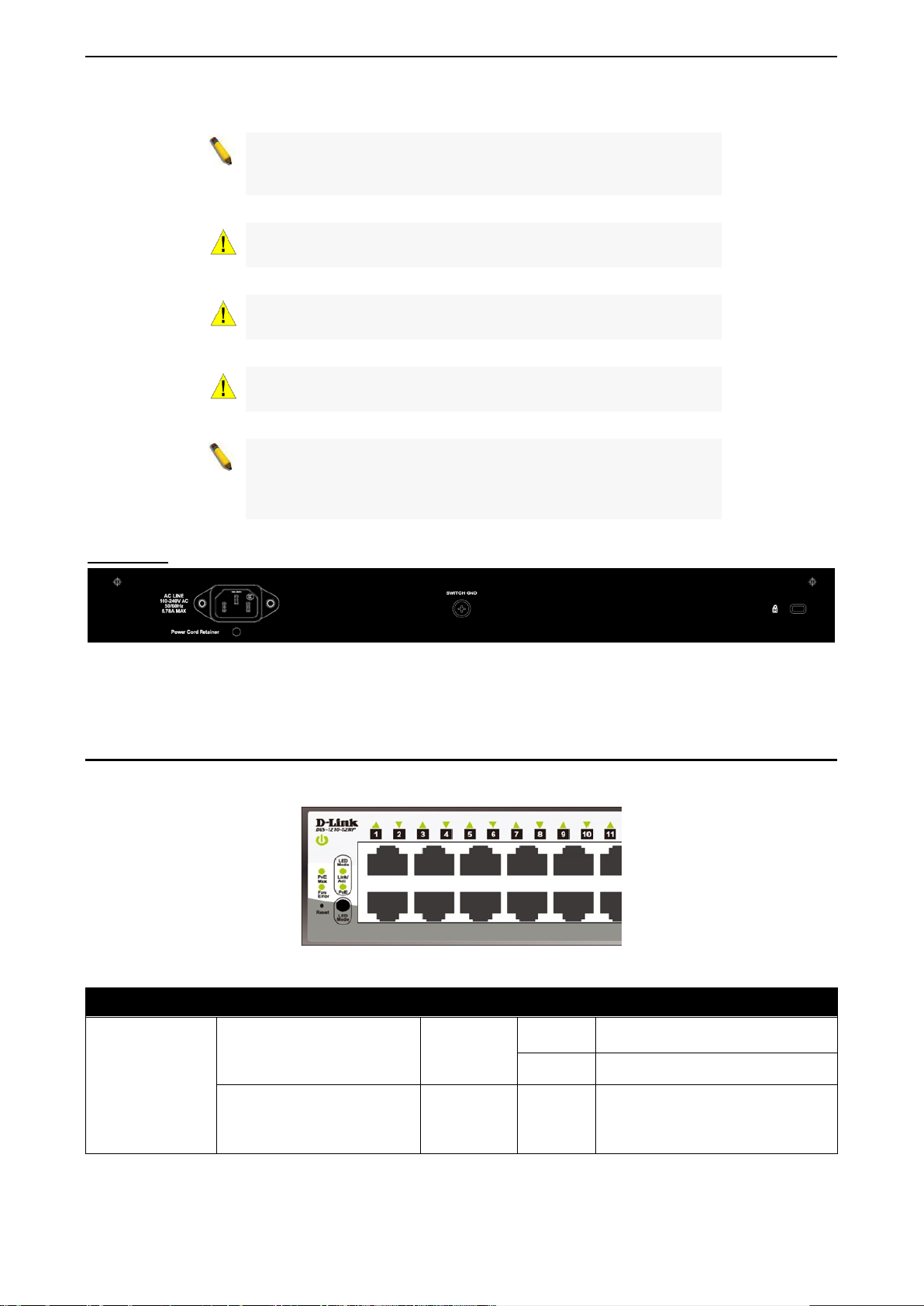
LED Indicators
The Switch supports LED i ndicat or s f or Power, F a n, a nd Li nk/Act for each port. The following shows the LED
indicators for the DGS-1210 series Smart Managed Switch along with an explanation of each indicator.
Figure 1.21 –LED Indicators on DGS-1210 series
Location LED Indicative Color Status Description
Power
Green
Per Device
Fan Error
(For DGS-1210-
Red Solid light
28P/28MP/52MP)
1133
Solid Light Power on.
Light off Power off.
The fan has runtime failure and is
brought offline.
Page 21

1 Product Introduction D-Link Smart Managed Switch User Manual
The PoE Max LED lights up when
65 Watts for
In the
device can be supported.
When the system power usage
range.
Mbps
When there is a secure 1000Mbps
any of the ports.
When there is reception or
Ethernet connected port.
When there is a secure
(or link) at any of the ports.
When there is reception or
Ethernet connected port.
When there is a secure 1000Mbps
any of the ports.
When there is reception or
Ethernet connected port.
When there is a secure 100Mbps
any of the ports.
When there is reception or
Ethernet connected port.
the total PoE output of Switch
reached or exceeded
DGS-1210-10P, 130 Watts for
PoE Max.
(For DGS-1210-
10P/10MP/28P/28MP/52MP)
Solid light
Amber
Blinking
Amber
DGS-1210-10MP, 193 Watts for
DGS-1210-28P, and 370 Watts
for DGS-1210-28MP/52MP.
meantime, no additional PoE
Total PoE output of Switch
reached guard band mode. (Max.
PoE budget < 7 Watts )
LED Per
10/100/1000
Copper Port
Link/Act
PoE Mode
Light off
Solid
Green
Blinking
Green
Green/Amber
Green
Amber Solid Light Error Condition.
Off Solid Off No Power feeding.
Solid
Amber
Blinking
Amber
Light off No link.
Solid Light Power feeding.
Solid
Green
does not reach the guard band
Ethernet connection (or link) at
transmission (i.e. Activity—Act) of
data occurring at a 1000Mbps
10/100Mbps Ethernet connection
transmission (i.e. Activity—Act) of
data occurring at a 10/100Mbps
Ethernet connection (or link) at
LED Per
100/1000Mbps
SFP Port
Link/Act
Blinking
Green
Green/Amber
Solid
Amber
Blinking
Amber
Off Solid off No link.
14
transmission (i.e. Activity—Act) of
data occurring at a 1000Mbps
Ethernet connection (or link) at
transmission (i.e. Activity—Act) of
data occurring at a 100Mbps
Page 22

2 Hardware Installation D-Link Smart Managed Switch User Manual
2 Hardware Installation
This chapter provides unpacking and installation information for the D-Link Smart Managed Switch.
Safety Cautions
To reduce the ris k of bodil y injur y, electric al shock , fire and dam age to the eq uipm ent, observe the fol lowing
precautions:
• Observe and follow service markings
Do not service any product except as explained in your system documentation.
Opening or removing covers that are marked with the triangular s ym bol with a lightning bolt ma y
expose you to electrical shock.
• Only a trained service technician should service components inside these compartments.
• If any of th e following conditions occur , unplug the product from the electrical outlet and replace the
part or contact your trained service provider:
The power cable, extension cable, or plug is damaged.
An object has fallen into the product.
The product has been exposed to water.
The product has been dropped or damaged.
The product does not operate correctly when you follow the operating instructions.
• Keep your system away from radiators and heat sources. Also, do not block cooling vents.
• Do not spill food or liquids on your system components, and never operate the product in a wet
environment. If the system gets wet, contact your trained service provider.
• Do not push an y objects int o the openings of your s ystem . Doing so c an ca use f ir e or el ectric shock b y
shorting out interior components.
• Use the product only with approved equipment.
• Allow the product to cool before removing covers or touching internal components.
• Operate the product on ly from the type of extern al po wer sour c e i nd icate d o n t h e elec tr ical r at ings lab el.
If you are not sure of the t ype of power source required, consu lt your service provider or loc al power
company.
• Also, be sure th at attached devices are electr ically rated to operate with the power available in your
location.
• Use only approved power cable(s). If you have not been provided with a power cable for your system or
for any AC powered o ption intend ed for your s ystem, purchase a power cab le that is appro ved for use
in your country. The p ower c able m ust be rated f or the prod uct and f or the volt age and c urrent m arked
on the product’s e lectrical ratings labe l. The voltage and curre nt rating of the cabl e should be greater
than the ratings marked on the product.
• To help prevent electr ic shock, plug the s ystem and peripher al power cables into properly grounded
electrical outlets.
• These cables are equipped with three-prong plugs to help ensure proper grounding. Do not use
adapter plugs or rem ove the grounding prong fr om a cable. If you mus t use an extension cable, use a
3-wire cable with properly grounded plugs.
• Observe extension cable and p ower strip r ati ngs. Make s ure t hat th e tota l am pere rat ing of all prod ucts
plugged into the extensio n cable or power strip does n ot exceed 80 percent of th e amper e ratings lim it
for the extension cable or power strip.
• To help protect your system from sudden, transie nt incr eases and dec reases in electrica l power, use a
surge suppressor, line conditioner, or uninterruptible power supply (UPS).
• Position system c ables and power cab les carefull y; route cables s o that they cannot be stepped on or
tripped over. Be sure that nothing rests on any cables.
• Do not modify power ca bles or plugs. Consult a licensed elec trician or your power company for s ite
modifications.
• Always follow your local/national wiring rules.
1155
Page 23
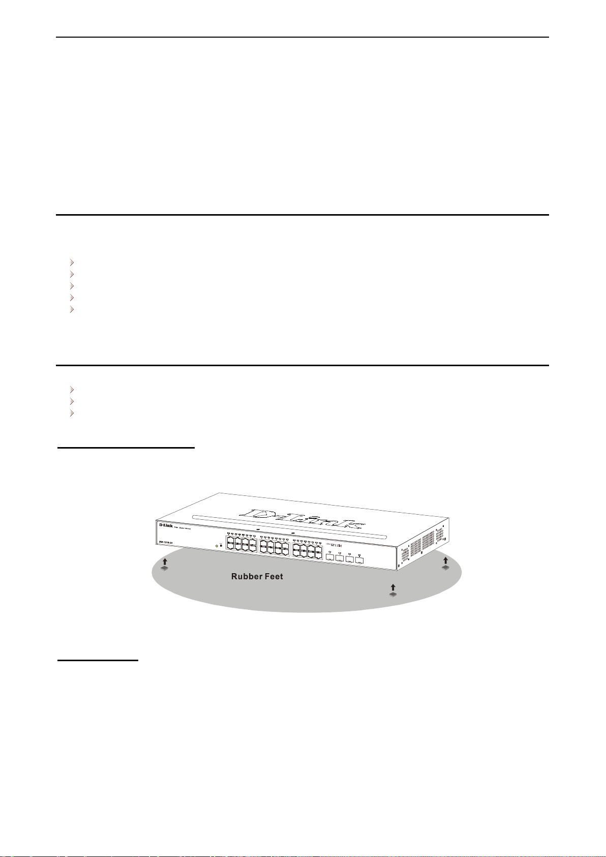
2 Hardware Installation D-Link Smart Managed Switch User Manual
• When connecting or d isconnectin g power to hot-pluggabl e power supp lies, if off ered with your system,
observe the following guidelines:
Install the power supply before connecting the power cable to the power supply.
Unplug the power cable before removing the power supply.
If the system has multiple s ources of power, disconnect power from the s ystem by unplugging a ll
power cables from the power supplies.
• Move products with care; e nsure that all casters and/o r stabilizers are firm ly connected to the system .
Avoid sudden stops and uneven surfaces.
Step 1: Unpacking
Open the shipping carton and carefully unpack its contents. Please c onsult the packing list located in the
User Manual to mak e sure all items are pr esent a nd undam aged. If any item is mis sing or damaged, please
contact your local D-Link reseller for replacement.
One D-Link DGS-1210 Smart Managed Switch
One Multilingual Getting Started Guide
User Guide CD
Power cord and Power Cord Retainer or external power adapter(DGS-1210-10P only)
Rack-mount kit and rubber feet
If any item is found missing or damaged, please contact the local reseller for replacement.
Step 2: Switch Installation
For safe switch installation and operation, it is recommended that you:
Visually inspect the power cord to see that it is secured fully to the AC power connector.
Make sure that there is proper heat dissipation and adequate ventilation around the switch.
Do not place heavy objects on the switch.
Desktop or Shelf Installation
When installing the switc h on a desktop or shelf, the r ubber feet included w ith the device must be attac hed
on the bottom at each cor ner of the device’s base. All ow enough ventilation s pace between the dev ice and
the objects around it.
Figure 2.1 – Attach the adhesive rubber pads to the bottom
Rack Installation
The switch can be mounted in an EIA standard size 19-inch r ack, which can be plac ed i n a wirin g closet with
other equipment. T o install, attac h the m ounting br ackets to th e switc h’s side p anels (one on each s ide) and
secure them with the screws provided (please note that these brackets are not designed for palm size
switches).
16
Page 24
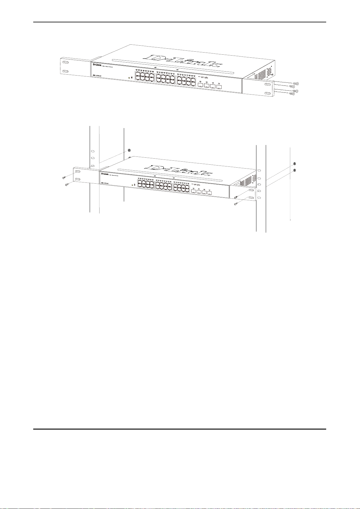
2 Hardware Installation D-Link Smart Managed Switch User Manual
Figure 2.2 – Attach the mounting brackets to the Switch
Then, use the screws provided with the equipment rack to mount the switch in the rack.
Figure 2.3 – Mount the Switch in the rack or chassis
Please be aware of following safety Instructions when installing:
A) Elevated Oper ating Ambient - If ins talled in a closed or m ulti-unit rack assem bly, the operating ambient
temperature of the rac k environm ent ma y be greater than room ambient. T herefor e, considera tion should b e
given to installing the equ ip ment in an environment compatible with the maximum ambient temperature (Tma)
specified by the manufacturer.
B) Reduced Air Flow - Installation of the e quipment in a rack should be such that the amount of air flow
required for safe operation of the equipment is not compromised.
C) Mechanical Loading - Mounting of the equipm ent in the r ack s hould be such th at a hazar dous c onditio n is
not achieved due to uneven mechanical loading.
D) Circuit Overloading - Consideration should be given to the connection of the equipment to the supply
circuit, and the eff ect that overl oading of the circu its might hav e on overc urrent prot ection and s uppl y wiring.
Appropriate consideration of equipment nameplate ratings should be used when addressing this concern.
E) Reliable Earthing - Reliable earthing of rack-mounted equipment should be maintained. Particular
attention should be give n to supply connecti ons other than direct c onnections to the branch c ircuit (e.g. use
of power strips)."
Step 3: Plugging in the AC Power Cord with Power Cord Clip
To prevent accidental removal of the AC power cord, it is recommended to install the power cord clip
together with the power cord.
A) With the rough side facing down, insert the Tie Wrap into the hole below the power socket.
1177
Page 25
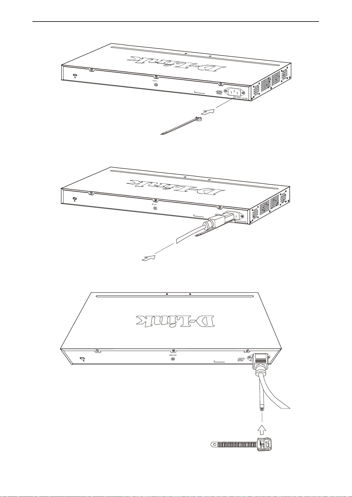
2 Hardware Installation D-Link Smart Managed Switch User Manual
Figure 2.4 – Insert Tie Wrap to the Switch
B) Plug the AC power cord into the power socket of the Switch.
Figure 2.5 – Connect the power cord to the Switch
C) Slide the Retainer through the Tie Wrap until the end of the cord.
Figure 2.6 – Slide the Retainer through the Tie Wrap
18
Page 26
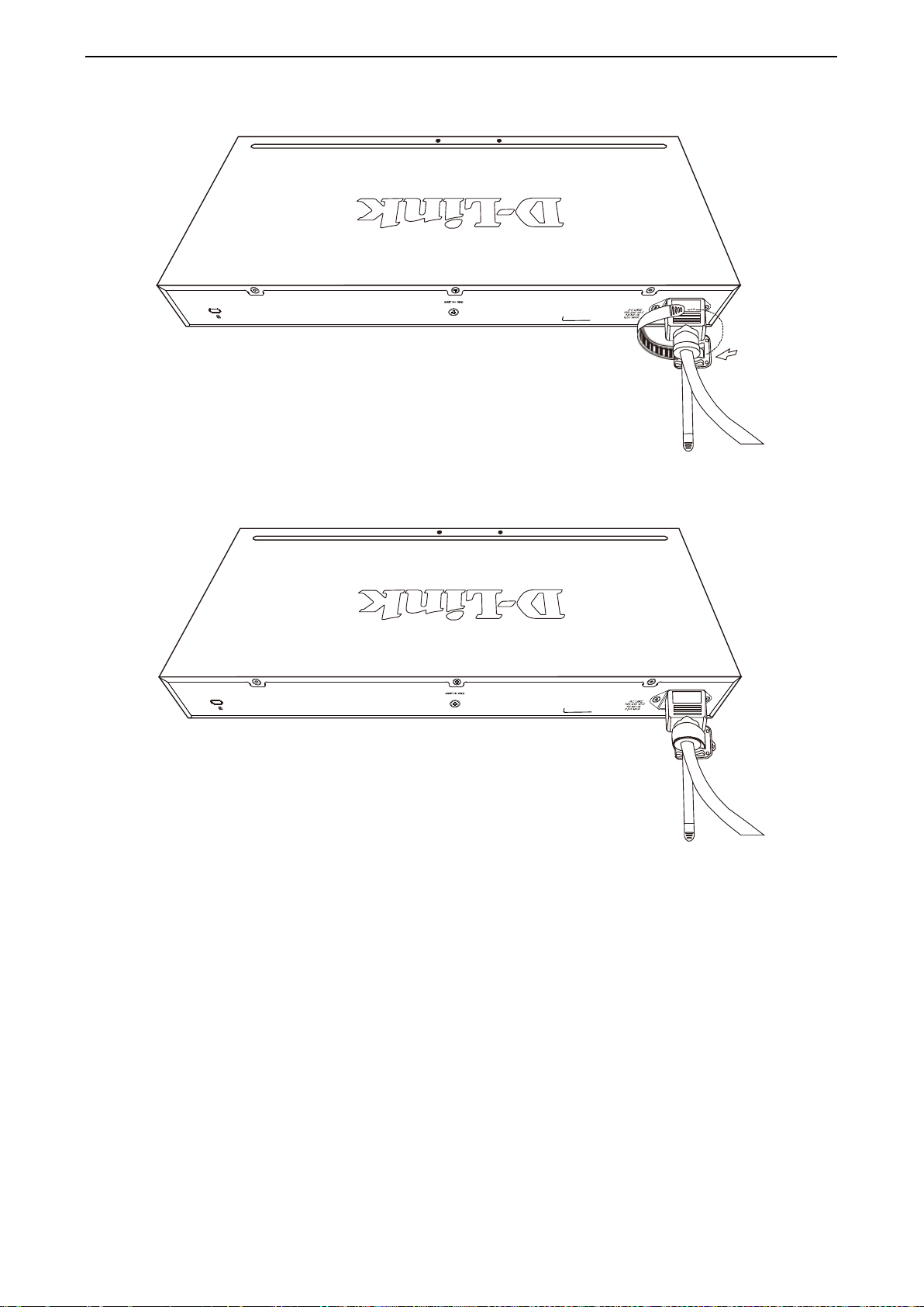
2 Hardware Installation D-Link Smart Managed Switch User Manual
D) Circle the tie of the Retainer around the power cord and into the locker of the Retainer.
Figure 2.7 – Circle around the power cord
E) Fasten the tie of the Retainer until the power cord is secured.
Figure 2.8 – Secure the power cord
F) Users may now connec t the AC power cord to an electrica l outlet (preferably one that is grou nded and
surge protected).
1199
Page 27
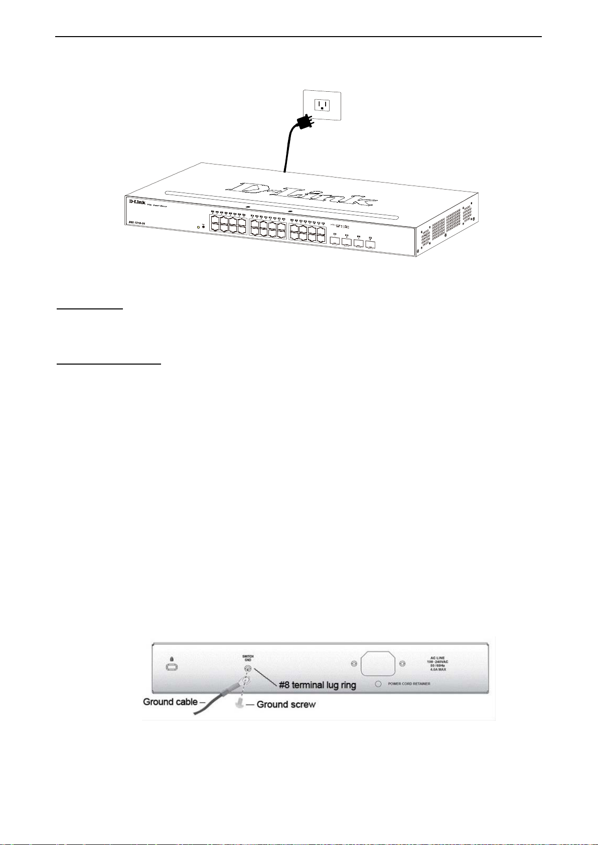
2 Hardware Installation D-Link Smart Managed Switch User Manual
Figure 2.9 – Plugging the switch into an outlet
Power Failure
As a precaution, th e switch s hould be u nplugged in cas e of power f ailure. W hen po wer is resum ed, plug t he
switch back in.
Grounding the Switch
This section describes how to connect the DGS-1210 Series Switch to ground. You must complete this
procedure before powering your switch.
Required Tools and Equipment
• Ground screws (included in the accessory kit): One M4 x 6 mm (metric) pan-head screw.
• Ground cable (not included in the accessory kit): T he grounding cable should be s ized according to
local and national installation requirements. Depending on the power supply and system, a 12 to 6
AWG copper conductor is required for U.S installation. Commercially available 6 AWG wire is
recommended. The length of the cable depends on the proximity of the switch to proper grounding
facilities.
• A screwdriver (not included in the accessory kit)
The following steps let you connect the switch to a protective ground:
Step 1: Verify if the system power is off.
Step 2: Use the ground c able to place t he #8 term inal lug ring on top of the ground-screw opening, as
seen in the figure below.
Step 3: Insert the ground screw into the ground-screw opening.
Step 4: Using a screwdriver, tighten the ground screw to secure the ground cable to the switch.
Step 5: Attach the terminal lug ring at th e other e nd of the gr ound ing cable to a n appr opriate gr ound ing
stud or bolt on rack where the switch is installed.
Step 6: Verify if the connections at the ground connector on the switch and the rack are securely
attached.
Figure 2.10 – Connect a Grounding Cable
20
Page 28
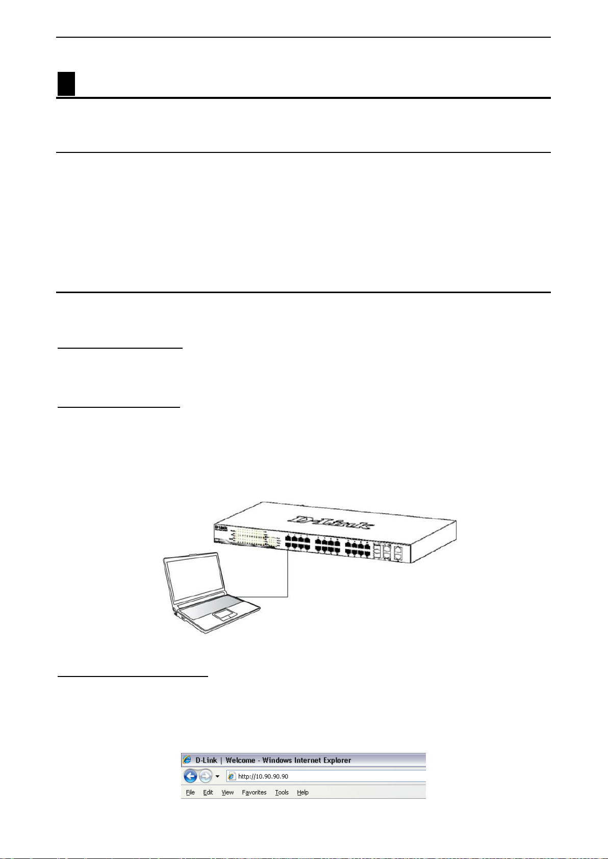
3 Getting Started D-Link Smart Managed Switch User Manual
3 Getting Started
This chapter introduces the management interface of D-Link Smart Managed Switch.
Management Options
The D-Link Smart Managed Switch can be managed through any port on the device by using the Web-based
Management.
Each switch must be assigned its own IP Address, which is used for communication with Web-Based
Management or a SNMP network manager. The PC should have an IP address in the same range as the
switch. Each switch can allow up to four users to access to the Web-Based Management concurrently.
Please refer to the following installation instructions for the Web-based Management.
Using Web-based Management
After a successf ul ph ysica l ins ta lla tio n, you can configure the Switch, monitor the network status , an d d is play
statistics using a web browser.
Supported Web Browsers
The embedded Web-based Management currently supports the following web browsers:
Web Browser via IE8(or later version), Firefox, Chrome and Safari.
Connecting to the Switch
You will need the following equipment to begin the web configuration of your device:
1. A PC with a RJ-45 Ethernet connection
2. A standard Ethernet cable
Connect the Ethernet cable to any of the ports on the front panel of the switch and to the Ethernet port on the
PC.
Figure 3.1 – Connected Ethernet cable
Login Web-based Management
In order to login and config ure the s witch vi a an Ether net conn ectio n, the PC must have an IP addres s in t he
same subnet as the s witc h. For example, if the switch has an IP address of 10.90.90.90, the PC should have
an IP address of 10.x.y.z (where x/y is a num ber betw een 0 ~ 254 and z is a number betwee n 1 ~ 254), and
a subnet mask of 255.0.0.0. There are two ways to launch the Web-based Management, you may either click
the Web Access button at the top of the SmartConsole Utility or open the web browser and enter 10.90.90.90
(the factory-default IP address) in the address bar. Then press <Enter>.
2211
Page 29
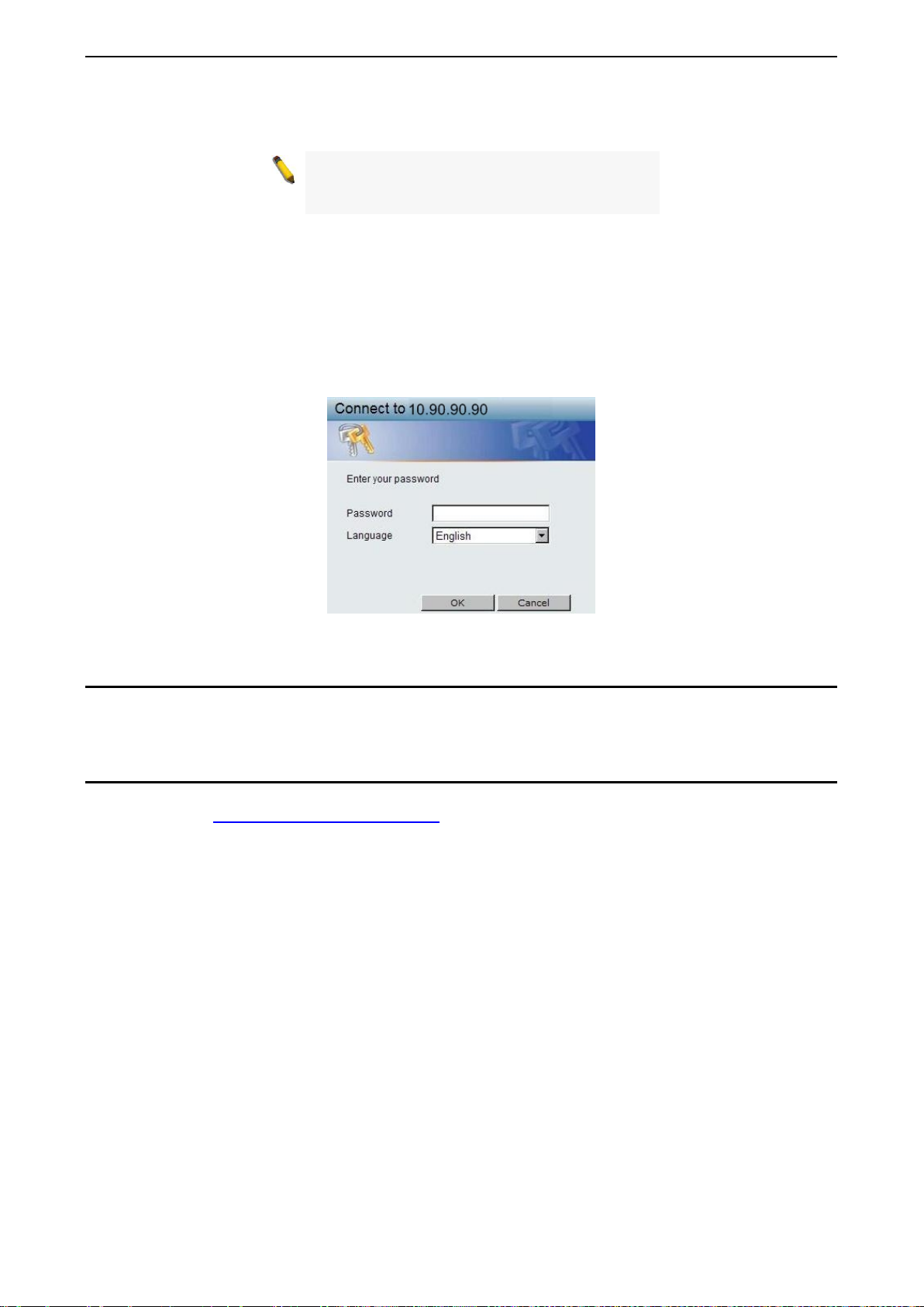
3 Getting Started D-Link Smart Managed Switch User Manual
Figure 3.2 –Enter the IP address 10.90.90.90 in the web browser
NOTE: T he switch's f actor y default IP addres s is
10.90.90.90 with a subne t m ask of 255.0.0 .0 and
a default gateway of 0.0.0.0.
The web configuration can also be accessed through the SmartConsole Utility. Open the SmartConsole
Utility and double-click the switch as it appears in the Monitor List. This will automatically load the web
configuration in your web browser.
When the following logon dialog box appears, enter the password and choose the language of the W ebbased Management interface then click OK.
The switch supports 10 languages including English, Traditional Chinese, Simplified Chinese, German,
Spanish, French, It alian, Portuguese, Japanese and Rus sian. By default, the password is admin and the
language is English.
Figure 3.3 – Logon Dia log Box
Smart Wizard
After a successful login, the Smart Wizard will guide you through essential settings of the D-Link Smart
Managed Switch. Please refer to the Smart Wizard Configuration section for details.
Web-based Management
By clicking the Exit button in the Smart Wizard, you wi ll e nter the Web-based M an agement interface. Please
refer to Chapter 4 Web-based Switch Configuration
for detailed instructions.
22
Page 30
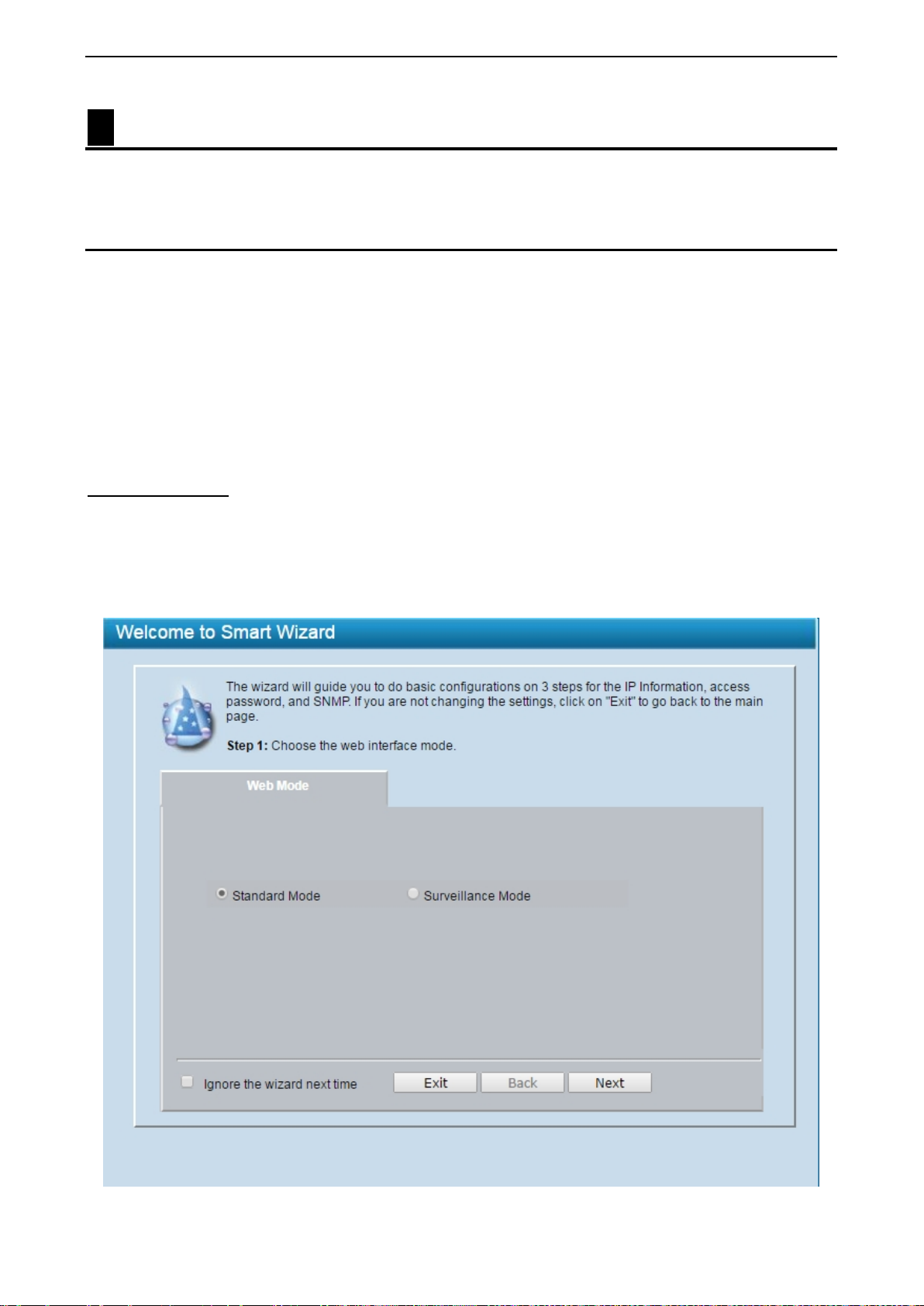
4 Web-based Switch Configuration D-Link Smart Managed Switch User Manual
4 Web-based Switch Configuration
The features and f unctions of the D-Link Smart Managed Switc h can be configured f or opt im um us e through
the Web-based Management Utility.
Smart Wizard Configuration
The Smart W izard is a configuration utility that is laun ched the first time the Web UI is ac cessed. It allows
users to configure basic settings such as the switch mode, management IP, password and SNMP. It can also
be used to switch between Standard Mode and Surveillance Mode Web UI types.
Standard Mode is used to manage the n etwork and system elements of the switch. Surveillanc e Mode is a
dedicated user interf ace designed for monitoring an d managing the surveillance and IP security device on
your network.
To switch between the two t ypes of interfac es, you can re-r un the Smart W izard that is presented w hen you
access the web interface of the device.
Step 1 – Web Mode
After a successful login, the Smart Wizard will guide you through essential settings of the D-Link Smart
Managed Switch. The initial page allows the user to choose between Standard Mode and Surveillance
Mode on the switch. This can be changed at any time by returning to the Smart Wizard.
If you do not plan to change anything, click Exit to leave the W izard and enter the W eb Interface. You can
also skip it by clicking Ignore the Wizard next time for the next time you logon to the Web-based
Management.
Figure 4.1 – Web Mode in Smart Wizard
2233
Page 31

4 Web-based Switch Configuration D-Link Smart Managed Switch User Manual
The fields that can be configured are described below:
Item Description
Select the Standard Mode to continue the f ollowing settings or s elect
Web Mode
Click Next to enter the next configuration page.
Step 2 – IP Information
The IP Information page allows the user to conf igure IP address assignm ent method, the static IP addres s,
netmask and gateway address.
the Surveillance Mode to continue the Sm art Wizard in Surveillance
Mode.
Figure 4.2 – IP Information in Smart Wizard
The fields that can be configured are described below:
Item Description
Static
DHCP Select DHCP option to obtain IP address settings from a DHCP server.
IP Address
Netmask Specifies the Netmask to be configured.
Gateway Specifies the default Gateway IP address to be configured.
BOOTP Select BOOTP option to be used on the switch.
Click Next to enter the next Password setting page.
Select Static option to manually conf igure and us e IP address settings
on this switch.
Specifies the IP address to be configured.
24
Page 32

4 Web-based Switch Configuration D-Link Smart Managed Switch User Manual
Cameras for the cameras to be
Tick the Ignore the wizard next time option to skip the Smart Wizard on the next login.
NOTE: The Smart Wizard supports quick settings for IPv4 network.
NOTE: The switch wil l probe IP-Cameras every 30 seconds. If and
IP-Camera is not in the sa me subnet as the switch, the IP-Camera
will not be automatically discovered. Place the switch managem ent
IP in the same subnet as the IPautomatically added to the Survei llanc e Mod e Web UI.
Step 3 – Password Type the desired new password in the Password box and again in the Confirm Password, then click the
Apply&Save button to accept the changes made and enter the next SNMP setting page. Tick the Ignore the
wizard next time option to skip the Smart Wizard on the next login.
Figure 4.3 – Password in Smart Wizard
Step 4 – SNMP (Only for Standard Mode)
The SNMP Setting allows you to quickly ena ble/disable the SNMP function. The default SNMP Setting is
Disabled. Click Enabled and then click Apply to make it effective.
2255
Page 33

4 Web-based Switch Configuration D-Link Smart Managed Switch User Manual
Mode and Surveillance Mode
features enables in one interface will be made
and the surveillance
Figure 4.4 – SNMP in Smart Wizard
NOTE: Changing the system IP address will
disconnect you from the current connection.
Please enter the correct IP address in the Web
browser again and make sure your PC is in the
same subnet with the switch. See Login Webbased Management for a detailed description.
NOTE: Standard
Web UIs share the same configuration files. Any
available in the other interface, for example: PoE
scheduling, SNMP settings
VLAN in use.
If you want to change the settings, click Apply and start a new web browser.
Figure 4.5 – Confirm the changes of IP address in Smart Wizard
26
Page 34

4 Web-based Switch Configuration D-Link Smart Managed Switch User Manual
If you close the web browser without
Web-based Management
After clicking the Exit button in Smart Wizard you will see the screen below:
Figure 4.6 – Web-based Management
The above image is the Web-based Management screen. The three main areas a r e the Tool Bar on top, the
Function Tree, and the Main Configuration Screen.
Item Area Description
Tool Bar
Function Tree
Main Configuration Screen
At the upper right corner of the screen the username and current IP address will be displayed.
Under the username is the Logout button. Click this to end this session.
Finally, b y clic k ing on the D-Link logo at the upper-left corner of the screen you will be redirected to the local
D-Link website.
To provide a quick and convenient way for essential utility functions
like firmware and configuration management.
By choosing diff erent functions in t he Function Tree, you can change
all the settings in the Main Configuration Screen.
To display the current status of your Switch by clicking the model name
on top of the function tree.
NOTE:
clicking th e Logout button first, then it wil l b e seen
as an abnormal ex it and the log in session will s till
be occupied.
2277
Page 35

4 Web-based Switch Configuration D-Link Smart Managed Switch User Manual
Tool Bar > Save Menu
The Save Menu provides Save Configuration and Save Log functions.
Figure 4.7 – Save Menu
Save Configuration
Select to save the entire c onfiguration changes to conf iguration ID 1 or 2 you have made to t he device to
switch’s non-volatile RAM.
Figure 4.8 – Save Configuration
Save Log
Save the log entries to your local drive and a pop-up mess age will prom pt you for the file pa th. You c an view
or edit the log file by using text editor (e.g. Notepad).
Figure 4.9 – Save Log
Tool Bar > Tools Menu
The Tools Menu offers global functi on controls suc h as Reset, Res et System, Reboo t Device, Configuration
Backup & Restore, Firmware Backup & Upgrade and Flash Information.
Figure 4.10 – Tool Menu
Reset
Provide a safe reset option for the Switch. All configuration settings in non-volatile RAM will be reset to
factory default except for the IP address.
Figure 4.11 – Tool Menu > Reset
Reset System
Provide another safe res et option for the Switch. All configuration settings in non-volat ile RAM will res et to
factory default and the Switch will reboot.
28
Page 36

4 Web-based Switch Configuration D-Link Smart Managed Switch User Manual
Figure 4.12 – Tool Menu > Reset System
Reboot Device
Provide a safe wa y to reboot the s ystem. Select YES or NO to save the cur rent settings before action. And
click Reboot to restart the switch.
Figure 4.13 – Tool Menu > Reboot Device
Configuration Backup and Restore
Allow the current c onfiguration sett ings to be save d to a file (not including the password), and if necessary,
you can restore configuration settings from this file. Two methods can be selected: HTTP or TFTP.
Figure 4.14 – Tool Menu > Configure Backup and Restore
HTTP: Backup or restore the configuration file to or from your local drive.
Backup/Restore Config ID Number: Select config_id 1 or config_id 2.
Click Backup to save the current settings to your disk.
Click Choose File to browse your inventories for a saved backup settings file.
Click Restore after selecting the backup settings file you want to restore.
TFTP: TFTP (Trivial File Transfer Protocol) is a file transfer protocol that allows you to transfer files to a
remote TFTP server. Specifies t he configuration 1 or 2 to be specifie d, TFTP Serv er IP Address with IPv4
or IPv6 address and TFTP File Name for the configuration file you want to save to / restore from.
Click Backup to save the current settings to the TFTP server.
Click Restore after selecting the backup settings file you want to restore.
Note: Switch will reboot after restore, and
all current configurations wi ll be lost.
2299
Page 37

4 Web-based Switch Configuration D-Link Smart Managed Switch User Manual
Firmware Backup and Upgrade
Allow for the firmware to be saved, or for an existing firmware file to be uploaded to the Switch. Two methods
can be selected: HTTP or TFTP.
Figure 4.15 – Tool Menu > Firmware Backup and Upload
HTTP: Backup or upgrade the firmware to or from your local PC drive.
Backup/Restore Image ID Number: Select image_id 1 or image_id 2.
Click Backup to save the firmware to your disk.
Click Choose File to browse your inventories for a saved firmware file.
Click Upgrade after selecting the firmware file you want to restore.
TFTP: Specifies the Image_id 1 or Im age_id 2 to backup or upgrade the f irmware to or f rom a rem ote TFTP
server. Specifies TFTP Server IP Address with IPv4 or IPv6 address and TFTP File Name for the
configuration file you want to save to / restore from.
Backup/Restore Image ID Number: Select Image_id1 or Image_id 2
Click Backup to save the firmware to the TFTP server.
Click Upgrade after selecting the firmware file you want to restore.
CAUTION: Do n ot disconnect the PC or remove
the power cord from device until the upgrade
completes. The Switch may crash if the
Firmware upgrade is incomplete.
Flash Information
This page displays the flash detail information of the Switch.
Figure 4.16 – Tool Menu > Flash Information
Tool Bar > Wizard
By clicking the Wizard button, you can return to the Smart Wizard if you wish to make any changes there.
30
Page 38

4 Web-based Switch Configuration D-Link Smart Managed Switch User Manual
Tool Bar > Online Help
The Online Help provides two ways of online support: D-Link Support Site will lead you to the D-Link
website where you can find online resources s uch as updated firm ware images; User Guide can offer a n
immediate reference for the feature definition or configuration guide.
Figure 4.17 – Online Help
Tool Bar > Surveillance Mode
By clicking the Surveillance Mode button to access the Surveillance Mode Web UI on the Switch. After
clicking the Surveillance Mode option in the Toolbar, the following pop-up window will appear.
Figure 4.18 – Survillance Mode Confirmation Message
The pop-up mes sage windo w above dis pla ys a mes sage that m entioned configur ations ne ed to be changed
when access to the Surveillance Mode is given.
Click the OK button to continue.
Click the Cancel button and return to the Standard Mode.
After successfully switching to the Surveillance Mode on the W eb UI of t he Switc h, the fol lowing window w ill
be presented.
Figure 4.19 – Survillance Mode Help Message
Click the OK button to continue, the following page will be presented.
3311
Page 39

4 Web-based Switch Configuration D-Link Smart Managed Switch User Manual
Figure 4.20 – Survillance Mode
Scroll to the bottom of the page and click the OK button to continue to the Web UI. For more detail
information of Surveillance Mode.
instructions.
Please refer to Chapter 5 Surveillance Mode Configuration for detailed
Function Tree
All configuration opt ions on the switc h are accessed through the Setup menu on the left s ide of the scr een.
Click on the setup item that you want to configure. The following s ections provid e more detailed description
of each feature and function.
Figure 4.21 –Function Tree
Device Information
The Device Inform ation pro vides an overvie w of the s witch, including essentia l inf ormation suc h as f irmware
& hardware information, and IP address.
32
Page 40

4 Web-based Switch Configuration D-Link Smart Managed Switch User Manual
Figure 4.22 – Device Information
It also offers an overall status of common software features:
RSTP: Click Settings to link to L2 Functions > Spanning Tree > STP Global Settings. Default is disabled.
Port Mirroring: Click Settings to link to L2 Functions > Port Mirroring. Default is disabled.
Storm Control: Click Settings to link to Security > Storm Control. Default is disabled.
DHCP Client: Click Settings to link to System > System Settings. Default is disabled.
Jumbo Frame: Click Settings to link to L2 Functions > Jumbo Frame. Default is disabled.
SNMP Status: Click Settings to link to SNMP > SNMP > SNMP Global Settings. Default is disabled.
802.1X Status: Click Settings to link to AAA > 802.1X > 802.1X Settings. Default is disabled.
Safeguard Engine: Click Settings to link to Security > Safeguard Engine. Default is enabled.
IGMP Snooping: Click Settings to link to L2 Functions > Multicast > IGMP Snooping. Default is disabled.
Power Saving: Click Settings to link to System > Power Saving. Default is disabled
System > System Settings
The System Setting allows the user to configure the IP address and the basic system information of the
Switch.
3333
Page 41

4 Web-based Switch Configuration D-Link Smart Managed Switch User Manual
Figure 4.23 – System > System Settings
IPv4 Information: T here are three ways for the s witc h to obtain an IP address: Static, DHCP (Dynamic Host
Configuration Protocol) and BOOTP.
When using static mode, the Interface Name, VLAN Name, Interface Admin State, IPv4 Address,
NetMask and Gateway ca n be m anuall y config ured. W hen using DH CP m ode, the S witch will fir st look f or a
DHCP server to provide it with an IP address (incl uding net work m ask and def ault gate way) before using the
default or previous ly entere d settings . By default the IP settin g is static mode with IP address is 10.90.90.90
and subnet mask is 255.0.0.0.
DHCP Option 12 State: Specifies the DHCP option 12 state is enabled or disabled.
DHCP Option 12 Host Name: Specifies the host name for DHCP.
DHCP Retry Times: Specifies the retry time of DHCP.
System Information: By entering a System Name and System Location, the device can m ore easily be
recognized through the SmartConsole Utility and from other Web-Smart devices on the LAN.
Login Timeout: The Login Timeout controls the idle time-out period for security purposes, and when there is
no action for a specific time span in th e Web-bas ed Management. If the current ses sion times out (ex pires),
the user is required a re-login before using the Web-based Management ag ain. Selective range is f rom 3 to
30 minutes, and the default setting is 5 minutes.
System > Password
Setting a password is a c ritical tool for managers to secure the Web-Smar t Switch. After ent ering the old
password and the new password twice, click Apply for the changes to take effect.
Figure 4.24 – System > Password Access Control
34
Page 42

4 Web-based Switch Configuration D-Link Smart Managed Switch User Manual
to adjust port speed settings
function when the speed links to 1000M force
System > Port Settings
In the Port Setting page, the status of all ports c an be m onitored an d adjusted f or optim um conf iguration. B y
selecting a range of por ts (From Po rt and To Po rt), the Speed can be set f or all selected por ts by click ing
Apply. Press the Refresh button to view the latest information.
Figure 4.25 – System > Port Settings
Speed: Gigabit Fiber connections can op erate i n 1000M Auto or Disabled. Copper connect ions can operate
in Forced Mode se ttings (1000M Full, 100M F ull, 100M Half, 10M Full, 10M Half), Auto, or D isabled. The
default setting for all ports is Auto.
NOTE: Be sure
appropriately after changing the connected cable
media types.
NOTE: All ports do not support MDI/MDI-X
mode.
MDI/MDIX:
A medium dependent interface (MDI) port is an Ethernet port connection typicall y used on the Network
Interface Card (NIC) or In tegrated NIC port on a PC. S witches and hubs usually use Medium dependent
interface crossover (MDIX) interface. When connecting the Switch to end stations, user have to use
straight through Ethernet cables to make sure the Tx/Rx pairs match up properly. When connecting the
Switch to other networking devices, a crossover cable must be used.
This switch provides a configurabl e MDI/MDIX function for users. The switches can be se t as an MDI port in
order to connect to other hubs or switches without an Ethernet crossover cable.
Auto MDI/MDIX is designed on the switch to detect if the connection is backwards, and automatically
chooses MDI or MDIX to properly match the connection. The default setting is “Auto” MDI/MDIX.
Flow Control: You can enable this func tion to m itigat e the traf fic c ongestion . Ports conf igured for full-duplex
use 802.3x flow control, half-duplex ports use backpressure flow control. The default setting is Disabled.
Auto Downgrade: Enable or disable automaticall y downgrading advertised s peed. This function onl y takes
effect, when Speed is configured as Auto.
Capability Advertised: When the Speed is set to Auto, these capabilities are advertised during autonegotitation.
System > Port Description
Port description can be given on this page.
3355
Page 43

4 Web-based Switch Configuration D-Link Smart Managed Switch User Manual
Figure 4.26 – System > Port Description
From Port / To Port: Specifies the range of ports to describe.
Description: Specifies the description for the chosen ports.
Click Apply to set the description in the table.
System > DHCP Auto Configuration
This page allows you to enable the DHCP Auto Configuration feature on the Switch. When enabled, the
Switch becomes a DHCP cl ient and gets the configuration file f rom a TFTP server automatically on next boot
up. To accomplish this, the DHCP server m ust deliver the TFTP server IP address and configuration file
name information in the DHCP reply packet. The TFTP server must be up and running and store the
necessary configuration file in its base directory when the request is received from the Switch.
Figure 4.27 – System > DHCP Auto Configuration
System > DHCP Relay > DHCP Relay Global Settings
User can enable and configure DHCP Relay Global Settings on the Switch.
Figure 4.28 – System > DHCP Relay > DHCP Relay Glo bal Settings
DHCP Rel ay State: This field can be tog gl ed bet wee n E nab le d a nd D isa ble d us i ng t he pu ll-down menu. It is
used to enable or disable the DHCP Relay service on the Switch. The default is Disabled.
DHCP Rela y Hops Count Limit (1-16): T his f ield allo ws an e ntr y betwee n 1 and 16 to def ine the m axim um
number of router hops DHCP messages can be forwarded across. The default hop count is 4.
36
Page 44

4 Web-based Switch Configuration D-Link Smart Managed Switch User Manual
If the Switch receives a packet that
DHCP Relay T ime Threshold (0-65535): Allows an entry between 0 and 65535 seconds, and defines th e
maximum time lim it for routing a DHCP pack et. If a value of 0 is e ntered, the Switch will n ot process the
value in the seconds fiel d of the D HC P pac ket. If a non-zero val ue is entered, the Switc h will us e t hat v al ue,
along with the hop count to determine whether to for wa r d a given DHCP packet.
DHCP Relay Agent Information Option 82 State: This field can be to ggl ed b et w een Enabled and Disabled
using the pull-down menu. It is used to enable or disable the DHCP Agent Information Option 82 on the
Switch. The default is Disabled.
Enabled – W hen this field is toggle d to Enabled the relay agent w ill insert and rem ove DHCP rela y
information (option 82 field) in mess ages between DH CP servers a nd clients. When the relay agent
receives the DHCP reques t, it adds the opt ion 82 inform ation, and the IP address of the relay agent
(if the relay agent is configured), to the packet. Once the option 82 inform ation has been adde d to
the packet it is sent on to the DHCP server. When the DHCP server receives the packet, if the server
is capable of option 82, i t can im plem ent policies lik e restricting the num ber of IP address es that c an
be assigned to a s ingle rem ote ID or circuit ID. Then the DHCP serv er echoes t he option 82 field in
the DHCP reply. The D HCP server unicasts reply to the back to the rel ay agent if the request was
relayed to the server b y the relay agent. The switch verifies that it originall y inserted the option 82
data. Finally, the rela y agent removes the optio n 82 field and forwar ds the packet to the s witch port
that connects to the DHCP client that sent the DHCP request.
Disabled - If the field is toggled to Disabled the relay agent will not inser t and remove DHCP re lay
information (option 82 field) in messages between DHCP servers and clients, and the check and
policy settings will have no effec t.
DHCP Relay Agent Information Option 82 Check: This field can be toggled between Enabled and
Disabled using the p ul l-do wn menu. It is used to enable or disab le t he S witch es a bility to check the validity of
the packet’s option 82.
Enabled – When the field i s togg led to Enabled, the re lay agent will check the va li dity of the packet’s
option 82 fields. If the s witch recei ves a pac ket tha t contai ns the option-82 f ield f rom a DHCP cli ent,
the switch drops t he packet beca use it is inval id. In pack ets received from DHCP servers, th e relay
agent will drop invalid messages.
Disabled - W hen the field is toggled to Disabled, th e relay agent will not check the validity of the
packet’s option 82 fields.
DHCP Relay Agent Information Option 82 Policy: This field can be toggled bet ween Replace, Drop, and
Keep by using the pull-down menu. It is used to set the Switches policy for handling packets when the DHCP
Agent Information Option 82 Check is set to Disabled. The default is Replace.
Replace - The option 82 field will be replaced if the option 82 field already exists in the packet
received from the DHCP client.
Drop - The packet will be dropped if the option 82 field already exists in the packet received from the
DHCP client.
Keep -The option 82 field w ill be retained if the optio n 82 field already exists in the packet received
from the DHCP client.
DHCP Relay Agent Information Option 82 Remote ID: This field can be toggled between Default and User
Define.
NOTE:
contains the option-82 field from a DHCP client
and the information-checking feature is enabled,
the switch drops the packet bec ause it is invalid.
However, in some inst ances, you might configure
a client with the option-82 field. In this situation,
you should disable the information-check feature
so that the switch d oes not remove the opti on-82
field from the packet. You can configure t he ac ti on
that the switch takes when it receives a packet
System > DHCP Relay > DHCP Relay Interface Settings
This page allows the us er to set up a server, b y IP address, for r elaying DHCP inform ation the switch. The
user may enter a previousl y conf igur e d IP i nterf ac e on the S w itch that w ill be c on nect ed d irec tly to the DHCP
with existing option-82 information by configuring
the DHCP Agent Information Option 82 Policy.
3377
Page 45

4 Web-based Switch Configuration D-Link Smart Managed Switch User Manual
server using the following window. Properly configured settings will be displayed in the DHCP Relay
Interface Table at the bottom of the f ollowing windo w, once th e user clic k s the Add button under t he Apply
heading. The user m ay add up t o four server I Ps per IP int erface on the Switch. Entries may be delet ed by
clicking Delete button.
Figure 4.29 – System > DHCP Relay > DHCP Relay Interf ace Settings
Interface: The IP interface on the Switch that will be connected directly to the Server.
Server IP: Enter the IP address of the DHCP server. Up to four server IPs can be configured per IP Interface.
Click Apply to implement changes made.
System > DHCP Local Relay Settings
The DHCP Local Relay Settings page allows the user to configure DHCP Local Relay. DHCP broadcasts are
trapped by the switch CPU, and replacement broadcasts are forwarded with Option 82. Replies from the
DHCP servers are trapped by the switch CPU, the Option 82 is removed and the reply is sent to the DHCP
Client.
Figure 4.30 - System > DHCP Local Relay Settings
DHCP Local Relay Status: Specifies whether DHCP Local Relay is enabled on the device.
Enabled – Enables DHCP Local Relay on the device.
Disabled – Disables DHCP Local Relay on the device. This is the default value.
Config VLAN by: Configure the VLAN by VID or VLAN Name of drop-down menu.
State: Specifies whether DHCP Local Relay is enabled on the VLAN.
Enabled – Enables DHCP Local Relay on the VLAN.
Disabled – Disables DHCP Local Relay on the VLAN.
DHCP Local Relay VID List: Displays the list of VLANs on which DHCP Local Relay has been defined.
Click the Apply button to implement changes made.
System > DHCPv6 Relay Settings
The DHCPv6 Relay Setting s page allows user to configure the DHCPv6 settings.
38
Page 46

4 Web-based Switch Configuration D-Link Smart Managed Switch User Manual
Figure 4.31 - System > DHCPv6 Relay Settings
DHCPv6 Relay Status: Specifies whether DHCPv6 Relay is enabled on the device.
Enabled – Enables DHCPv6 Relay on the device.
Disabled – Disables DHCPv6 Relay on the device. This is the default value.
DHCPv6 Relay Hops Count Limit (1-32): The field allows and entry between 1 and 32 to define the
maximum number of router hops DHCPv6 messages can be forwarded. The default hop count is 4.
DHCPv6 Relay Option37 State: Specifies the DHCPv6 Relay Option37 State to be enabled or disabled.
DHCPv6 Relay Option37 Check: Specifies the DHCPv6 Relay Option37 Check to be enabled or disabled.
DHCPv6 Relay Optio n37 Remote ID Type: Specifies the DHCPv6 Relay Optio n37 Remote ID t ype is CID
with User Defined, User Defined or Default.
Interface: Enter a name of the interface.
Server IP: Enter the server IP address.
Click the Apply button to implement changes made.
System > System Log Configuration > System Log Settings
System Log Configur ation featur e conta ins information for configuring various attr ibutes and proper ties. The
System Log Settings page allows user to enable or disable th e System Log and s pecify a m ethod for whic h
to save the switch log to the flash memory of the Switch.
Figure 4.32 – System > System Log Configuration > System Log Settings
System Log: To enable or disable the system log feature.
Click Apply to implement changes made.
System Log Save Mode Settings:
Save Mode: Use this drop-do wn menu to c hoos e the m ethod that will trig ger a lo g entr y. Choos e am ong On
Demand, Time Interval, and Log Trigger.
On Demand – Users who choose this method will only save log files when they manually tell the
Switch to do so, either using the Save Log link in the Save folder.
3399
Page 47

4 Web-based Switch Configuration D-Link Smart Managed Switch User Manual
Time Interval – Users who c hoose t his m ethod can c onf igure a tim e inter val b y w hich the Switch will
save the log files, in the box adjacent to this configuration f ield. The user may set a time between 1 an d
65535 minutes.
Log Trigger – Us ers wh o choose this method will have log fi les saved to t he Switch ever y time a lo g
event occurs on the Swtich.
Minutes (1-65535): To specify the time interval in minutes, for which a log entry is to be made.
Click the Apply button to implement changes made.
System > System Log Configuration > SysLog Host
System Logs record and manage events, as well as report errors and informational messages. Message
severity determines a s et o f event m es sages that wi ll be sent . Click Enable s o you can st art to c onf igure th e
related settings of the remote system log server, then press Apply for the changes to take effect.
Figure 4.33 – System > System Log Configuration > SysLog Host
Server IP Address: Select IPv4 or IPv6 then specify the IP address of the system log server.
UDP Port: Specifies the U DP port to which the serve r logs are sent. The possib le range is 1 – 65535, and
the default value is 514.
Time Stamp: Select Enable to time stamp log messages.
Severity: Specifies the minim um severity from which warning mess ages are sent to the server. There are
three le vels. When a severit y level is selected, a ll severity level choices ab ove the selection are selected
automatically. The possible levels are:
Warning - The lowest level of a device warning. The device is functioning, but an operational
problem has occurred.
Informational - Provides device information.
All - Displays all levels of system logs. And this is the default value.
Facility: Specifies an app lication f rom which s ystem logs are sent to t he rem ote s erver. Onl y one f acilit y can
be assigned to a single ser ver. If a second f acility level is as signed, the firs t facility is overwritten. T here are
up to eight facilities can be assigned (Local 0 ~ Local 7).
System > Time Profile
The Time Profile page allows users to configure the time profile settings of the device.
Figure 4.34 – System > Time Profile
40
Page 48

4 Web-based Switch Configuration D-Link Smart Managed Switch User Manual
Profile Name: Specifies the profile name.
Time(HH MM): Specifies the Start Time and End Time.
Weekdays: Specifies the work day.
Date: Select Date and specifies the From Day and To Day of the time profile.
Click Add to create a new time profile or click Delete to delete a time profile from the table.
System > Power Saving
The Power Saving mode feature reduces power consumption automatically when the R J-45 port is link do wn
or the connected devices are turned off.
By reducing power consumption, less heat is produced, resulting in extended product life and lower
operating costs. By default, the Link Status Detection is disabled. Click Apply to make the change effective.
Figure 4.35 – System > Pow er Saving
Advanced Power Saving Settings:
Type: Specifies the Power Saving type to be LED Shut-off, Port Shut-off or System Hibernation.
LED Shut-off - The LED Shut-off gets high priority. If the user select LED Shut-off, the profile
function will not take effect. It means the LED cann ot be turned on aft er Tim e Profile tim e’s up when
the state is disabled. On the contrary, if the LED is enabled, the Time Profile function will work.
Port Shut-off - The Port Shut-off state has high priority (the priority rule is the same as LED.)
Therefore, if the Port Shut-off sate is already disabled the Time Profile function will not take effect.
System Hibernation - In this mode, switches get most po wer-saving figures since main chips ets
(both MAC and PHY) are disabled for all ports, and energy required to power the CPU is minimal.
State: Specifies the power saving state to be Enabled or Disabled.
Time Profile 1: Specifies the time profile or None.
Time Profile 2: Specifies the time profile or None.
Port: Specifies the ports to be configure of the Power Saving.
Click Select All configure all ports, or click Clear to uncheck all port. Then click Apply to implement changes
made.
System > IEEE802.3az EEE Settings
The IEEE 802.3 EEE standard defines mechanisms and protocols intended to reduce the energy
consumption of network links during periods of low utilization, by transitioning interfaces into a low-power
state without interrupting the network connection. The transmitted and received sides should be
IEEE802.3az E EE compliance. By default, the 802. 3az EEE function is d isabled of the switc h. Users can
enable this feature by individual port via the IEEE802.3az EEE setting page.
4411
Page 49

4 Web-based Switch Configuration D-Link Smart Managed Switch User Manual
Figure 4.36 – System > IEEE802 .3az EEE Settings
From Port / To Port: A consecutive group of ports may be configured starting with the selected port.
State: Enabled or Disabled the IEEE802.3az EEE for the specified ports. By default, all ports are disabled.
Click Apply to implement changes made.
If the connection sp eed dr ops do wn f rom 1000M t o 10 0M, or the f irst l ink up t ak es lon ger tim e, ple ase f ollow
below steps and check again:
1. Upgrade drivers of your Ethernet adapter or LAN controller for the host PC.
2. Disable EEE function on the switch port.
System > D-Link Discover Protocol Settings
For the D-Link Discover y Protocol (DD P) supported d evice, this pa ge is an optio n for you to d isable DDP or
configure the DDP packet report timer.
Figure 4.37 – System > D-Link Discover Protocol Settings
D-Link Discover Protocol State: Enable or disable the Discover Protocol state. The default value is
enabled.
D-Link Discover Protocol Report Timer (Seconds): Configure the report timer of D-Link Discover Protocol
in seconds. The values are 30, 60, 90, 120 or Never.
Click the Apply button to implement changes made..
42
Page 50

4 Web-based Switch Configuration D-Link Smart Managed Switch User Manual
DDP Port Setting:
From Port / To Port: Specifies the range of ports to be configured for D-Link Discover Protocol of the Switch.
State: Specifies to enable or disable the D-Link Discover Protocol state for the specified ports.
Click Apply to implement changes made.
System > Firmware Information
The Firmware Information page displays the information of firmware. The user can specify which
configuration ID and image file to boot up when power on the Switch next time.
Figure 4.38 – System > Firmware Information
VLAN > 802.1Q VLAN
A VLAN is a group of ports that can be anywhere in the networ k, but communicate as though the y were in
the same area.
VLANs can be eas ily or gan ized to ref lect department groups (such as R&D, M arketin g), us age gr oups ( such
as e-mail), or multicast groups (multimedia applicatio ns such as video conferencing), an d therefore help to
simplify network management by allo wing users to move devices to a n ew VLAN without having to chang e
any physical connections.
The IEEE 802.1Q VLAN Configuration page provides powerful VID management functions. The original
settings have the VID as 1, no default name, and all ports as “Untagged”
Rename: Click to rename the VLAN group.
Delete VID: Click to delete the VLAN group.
Add New VID: Click to create a new VID group, assigning ports from 01 to 28 as Untag, Tag, or Not
Member. A port can be untagged in only one VID. To save the VID group, click Apply.
You may change the name accordingly to the desired groups, such as R&D, Marketing, email, etc.
4433
Page 51

4 Web-based Switch Configuration D-Link Smart Managed Switch User Manual
Figure 4.39 – Configuration > 802.1Q VLAN
Click Add to c reate a new VID group, e ntering the VID and VLAN name, assigning ports f rom 01 to 52 as
Untag, Tag or Not Member. To save the VID group, click Apply.
Figure 4.40 – Configuration > 802.1Q VLAN > Add VID
After click Apply, the 802.1Q VLAN Configuration Table will displayed with updates.
Figure 4.41 – Configuration > 802.1Q VLAN > Add VLAN
44
Page 52

4 Web-based Switch Configuration D-Link Smart Managed Switch User Manual
Click the VID number, the configuration of VLAN group which selected by user will displayed.
Change the port assignment then click Apply to implement changes made.
Figure 4.42 - Configuration > 802.1Q VLAN > VID Assignments
VLAN > 802.1Q VL AN PVID
The 802.1Q VLAN PVID setting allows user to conf igure the P VID for each ports. Click Apply to implem ent
changes made.
Figure 4.43 – Configuration > 802.1Q VLAN PVID
VLAN > Voice VLAN > Voice VLAN Global Settings
Voice VLAN is a feat ure that al lows you to autom atic ally place t he vo ice traf f ic fr om IP phone t o an as signed
VLAN to enhance the V oIP s er vice. With a higher priorit y an d i nd iv idual VL AN, the quality and the security of
VoIP traff ic are guar anteed . If a VoIP packet comes with a V LAN tag, the Voice V LAN func tion won’t r eplace
the original VLAN tag.
Figure 4.44 – VLAN > Voice VLAN > Voice VL AN Global Settings
Voice VLAN: Select to enable or disable Voice VLAN. The default is Disabled. After you enabled Voice
VLAN, you can configure the Voice VLAN Global Settings.
4455
Page 53

4 Web-based Switch Configuration D-Link Smart Managed Switch User Manual
Voice VLAN has higher priority than any
other features (including QoS). Therefore the
voice traffic will be operated according to the
VLAN ID: The ID of VLAN that you want to assign voice traff ic to. You must first create a VLAN f rom the
802.1Q VLAN page before you can assign a dedicated Voice VLAN. The member port you configured in
802.1Q VLAN settin g page will b e the static member port of voice VLAN. To dynamically add ports into the
voice VLAN, please enable the Auto Detection function
Priority: The 802.1p priority levels of the traffic in the Voice VLAN.
Aging Time (1-120): Enter a per iod of tim e ( in hour s) to r em ove a port from the v oice VLAN if t he port is an
automatic VLAN mem ber. When the last voice device stops sending traffic and the MAC address of this
voice device is aged out, the voice VLAN aging timer will start. The port will be removed from the voice VLAN
after the expiration of the voice VLAN aging timer. Selectable range is from 1 to 120 hours, and default is 1.
Click Apply to implement changes made.
Voice VLAN OUI Settings: This allows the user to configure the user-defined voice traffic’s OUI. An
Organizationall y Unique Identifier (OUI) is the first t hree bytes of the MAC ad dress. This identifier uniquely
identifies a vendor, manufacturer, or other organization.
There are some pr e-defined O UIs and when the user conf igures person al OUI , thes e pre-def ined O UIs m ust
be avoided. Below are the pre-defined voice traffic’s OUI:
OUI Vendor Mnemonic Name
00:E0:BB 3Com 3com
00:03:6B Cisco cisco
00:E0:75 Veritel veritel
00:D0:1E Pingtel pingtel
00:01:E3 Siemens siemens
00:60:B9 NEC/ Philips nec&philips
00:0F:E2 Huawei-3COM huawei&3com
00:09:6E Avaya avaya
Default OUI: Pre-defined OUI values, including brand names of 3COM, Cisco, Veritel, Pingtel, Siemens,
NEC/Philips, Huawei3COM, and Avaya.
User defined OUI: You can manuall y create a Telephon y OUI with a description. T he maximum num ber of
user defined OUIs is 10.
Select the OUI and press Add to the lower table to complete the Auto Voice VLAN setting.
Note:
Voice VLAN settin g and not impac ted by the QoS
feature.
Note: It is recommended setting the highest
priority for Voice VLAN to guar antee the q uality of
VoIP traffic.
VLAN > Voice VLAN > Voice VLAN Port Settings
The Voice VLAN Port Setti ngs page allows users to autom aticall y place the voic e traff ic from IP phone to a n
assigned VLAN to enhance the VoIP se rvic e . With a higher priority and ind ividual VLAN, th e qualit y and the
security of VoIP traffic are guaranteed.
46
Page 54

4 Web-based Switch Configuration D-Link Smart Managed Switch User Manual
n any
other features even QoS. Therefore the voice
It is recommended setting the highest
Figure 4.45 – VLAN > Voice VLAN > Voice VL AN Port Settings
From Port / To Port: A consecutive group of ports may be configured starting with the selected port.
Auto Detection: Switch will add ports to the voice VLAN automaticall y if it detects the device OUI m atches
the Telephony OUI configured in Voice VLAN OUI Setting page. Use the drop-down menu to enable or
disable the OUI auto detection function. The default is Disabled
Tagged / Untagged: Tagged or untagged the ports.
Click Apply to implement changes made and Refresh to refresh the voice vlan table.
Note: Voice VLAN has higher priority tha
traffic will be operated according to Voice VLAN
setting and not impacted by QoS feature.
Note:
priority for Voice V LAN to guara ntee the qual ity of
VoIP traffic.
VLAN > Voice VLAN > Voice Device List
The Voice Device List page displays the information of Voice VLAN.
Figure 4.46 – VLAN > Voice VLAN > Voice De vic e List
Select a port or all ports and click Search to display the Voice Device information in the table.
VLAN > Auto Surveillance VLAN > Auto Surveillance Properties
The Auto Surveillance Properties page allows user to configure and display the ports surveillance VLAN
settings and information.
4477
Page 55

4 Web-based Switch Configuration D-Link Smart Managed Switch User Manual
Figure 4.47 – VLAN > Auto Surveillance VLAN > Auto Surveillance Properties
Global Settings: To configure the related auto surveillance VLAN global settings.
Auto Surveillance VLAN: To enable or disable the auto surveillance VLAN state.
Surveillance VLAN ID: Specifies the surveillance VLAN ID. The range is from 2 to 4094.
Surveillance VLAN CoS: Specifies the priority of the surveillance VLAN. The range is from 0 to 7.
Tagged Uplink/Downlink Port: Specifies th e port or ports to b e tagg ed uplink port or do wnlink port for th e
Auto Surveillance VLAN.
Aging Time (1-65535): Specifies the aging time of surveillance VLAN. The range is from 1 to 65535 minutes.
The default value is 720 m inutes . The aging time is used to r em ove a port f rom surve illance VLAN if the port
is an automatic surve illance VLAN mem ber. When the last surve illance device s tops sending traff ic and the
MAC address of this sur veillance dev ice is aged out, t he surveillance VLAN agin g timer will be start ed. The
port will be removed from the surveillance VLAN after expiration of surveillance VLAN aging timer. If the
surveillance traffic resumes during the aging time, the aging timer will be reset and stop.
Discover Port (554, 1024-65535): Specifies the TCP/UDP port num ber for surveillance VL AN. The r ange is
either 554, or between 1 024 and 65535. This is used to configure the TCP/UDP port number for RTSP
stream snooping. ONVIF-c apable IPC and ONVIF-ca pable NVR utilize W S-Discovery to find other devices.
Once IPCs are disc overed, the Switch can further discover NVRs by snooping RTSP, HTTP, and HTTPS
packets between N VRs and IPCs. These pac kets cannot be snooped if t h e T CP/ U DP port is n ot equal to the
RTSP port number.
Log State: To enable or disable the log state of surveillance VLAN.
Click the Apply button to implement changes made.
VLAN > Auto Surveillance VLAN > MAC Settings and Surveillance Device
Similar as Vo ice VLA N, A uto Surveillance VLAN is a feat ure that all ows you to autom atically place t he video
traffic from D-Link IP cameras to an assigned VLAN to e nhance the IP surve illance service. W ith a higher
priority and individual VLAN, the quality and the security of surveillance traffic are guaranteed. The Auto
Surveillance VLAN function will check the source MAC address / VLAN ID on the incoming packets. If it
matches specified MAC address / VLAN ID, the packets will pass through switch with desired priority.
48
Page 56

4 Web-based Switch Configuration D-Link Smart Managed Switch User Manual
Figure 4.48 – VLAN > Auto Surveillance VLAN > MAC Settings and Surveillance Device
User-defined MAC Settings:
Component Type: Auto Surveillance VLAN wil l autom atically detect D-Link Surve illance D evices b y defaul t.
There are another five surveillance components that could be configured t o be auto-detected by the Auto
Surveillance VLAN. These five components are Video Management Server (VMS), VMS Client/Remote
viewer, Video Encoder, Network Storage and Other IP Surveillance Devices.
Description: Here to input the description for the component type.
MAC Address: User can manually create an MAC or OUI address for the surveillance component. The
maximum number of user defined MAC address is 5.
Mask: Specifies the mask address for the MAC or OUI.
Click Add to create a new surveillance component and Refresh to refresh the Auto Surveillance VLAN
summary table.
VLAN > Auto Surveillance VLAN > ONVIF IPC Information
The ONVIF IPC Information page displays the information on each IP camera connected to the switch.
Including the port number, IP address, MAC address, throughput and other information such as port
description and model name.
Figure 4.49 – VLAN > Auto Surveillance VLAN > ONVIF IPC Information
VLAN > Auto Surveillance VLAN > ONVIF NVR Information
The ONVIF NVR Inform ation page displa ys the inform ation on each NVR con nected to the s witch. Includi ng
the port number, IP address, MAC address , IP-Camera number, throug hput and description re lating to the
cameras connected to the NVR, such as the group nam e, total number of cameras and the port and IP
address of each camera.
4499
Page 57

4 Web-based Switch Configuration D-Link Smart Managed Switch User Manual
Figure 4.50 – VLAN > Auto Surveillance VLAN > ONVIF NVR Information
L2 Functions > Jumbo Frame
D-Link Gigabit Sm art Managed Switches support jumbo fr ames (frames larger than the Et hernet fram e size
of 1536 bytes) of u p to 10000 bytes (tagged) . Default is disabled, Select Enabled then click Apply to t ur n on
the jumbo frame support.
Figure 4.51 – L2 Functions > Jumbo Frame
L2 Functions > Port Mirroring
Port Mirroring is a method of monitoring network traffic that forwards a copy of each incoming and/or
outgoing packet f rom one port of the Switc h to anoth er port, wher e the pac ket can be s tudied. T his enables
network managers to better monitor network performances.
Figure 4.52 – L2 Functions > Port Mirroring
Selection options for the Source Ports are as follows:
TX (transmit) mode: Duplicates the data tr ans mitted from the sourc e por t a nd f or war ds it to the Target Port.
Click “all” to include all ports into port mirroring.
RX (receive) mode: Duplicates the dat a that is received from the sour ce port and forwards it to the Target
Port. Click “all” to include all ports into port mirroring.
TX/RX (transmit and receive) mode: Duplicate both the data trans mitted from and data sent to the s ource
port, and forwards all the data to the assigned Target Port. Click “all” to include all ports into port mirroring.
None: Turns off the mirroring of the port. Click “all” to remove all ports from mirroring.
L2 Functions > Loopback Detection
The Loopback Detec tion function is used to detec t the loop created by a spec ific port while Spanning Tr ee
Protocol (STP) is not enabled in the network, especially when the down links are hubs or unmanaged
switches. The Switch will automatically shutdown the port and sends a log to the administrator. The
Loopback Detection port will be unlocked when the Loopback Detection Recover Time times out. The
Loopback Detection func tion can be implem ented on a range of ports at t he same time. You m ay enable or
disable this function using the pull-down menu.
50
Page 58

4 Web-based Switch Configuration D-Link Smart Managed Switch User Manual
Figure 4.53 – L2 Functions > Loopback Detection
Loopback Detection: Use the drop-down menu to enable or disable loopback detection. The default is
Disabled.
Mode: Specifies Port-base d or VLAN-based m ode. If port-based mode is selec ted, the loop happe ning port
will be shut down and affect all m ember VLANs. If V LAN-based mode is selected, onl y the member por t in
the loop happening VLAN will be shut down.
VID List: Specifies the VID .
Interval (1-32767): Set a Loop detection Interval between 1 and 32767 seconds. The default is 2 seconds.
Recover Time (0 or 60-1000000): Time allowed (in seconds) for recovery when a Loopback is detected.
The Loop Detection Recover Time can be set at 0 seconds, or 60 to 1000000 seconds. Entering 0 will
disable the Loop Detection Recover Time. The default is 60 seconds.
From Port: The beginning of a consecutive group of ports may be configured starting with the selected port.
To Port: The ending of a consecutive group of ports may be configured starting with the selected port.
State: Use the drop-down menu to toggle between Enabled and Disabled. Default is Disabled.
Click the Apply button to implement chang es made or click Ref r es h to refresh the Loopback Detection table.
L2 Functions > MAC Address Table > Static MAC
This feature provides two d istinct f unctions . T he M AC Ad dr ess Learning table allows turni ng of f the f unction
of learning MAC address a utomatically, if a port isn' t specified as an upl ink port (for example, connec ts to a
DHCP Server or Gateway). By default, this feature is disabled.
Figure 4.54 – L2 Functions > MAC Address Table > Static Mac Address
5511
Page 59

4 Web-based Switch Configuration D-Link Smart Managed Switch User Manual
The Static MAC Address Lists table displays the static MAC addresses connected, as well as the VID.
Add Static MAC Address: you need to select the assigned Port number. Enter both the Mac Address and
VID, and then Click Add. Click Delete to remove one entry or click Delete all to clear the list.
By disabling MAC Address Auto Lear ning cap abilit y and s pecif ying t he static MAC addresses, the netw ork is
protected from potential threats like hackers, because traffic from illegal MAC addresses will not be
forwarded by the Switch.
L2 Functions > MAC Address Table > Dynamic Forwarding Table
For each port, this tabl e displays the MAC address l earned by the Switch. To add a MAC address to the
Static Mac Address List, cli ck the Add c h ec kbox, and then click Apply associated with the identified address.
Figure 4.55 – L2 Functions > MAC Address Table > Dynam i c Fo r warding Tabl e
L2 Functions > Spanning Tree > STP Bridge Global Settings
The Switch implements three versions of the Spanning Tree Protocol, the Rapid Spanning Tree Protocol
(RSTP) as defined b y the IEEE 802.1w specificatio n and a version compatible with the IE EE 802.1D STP
and Multiple Spanning T ree Protocol (MSTP) as defined by the IEEE8 02.1 specific ation. RSTP can operate
with legacy equipment implementing IEEE 802.1D, however the advantages of using RSTP will be lost.
The IEEE 802.1w Rapid Sp anning T ree Pr otocol ( RSTP) evolved f rom t he 802.1D STP s tandard. R STP was
developed in order to ov ercome some lim itations of STP that impede th e function of som e recent switching
innovations. The basic function and much of the terminology is the same as STP. Most of the settings
configured for STP are als o used for RSTP. T his section introd uces som e new Spannin g Tree c oncepts and
illustrates the main differences between the two protocols.
The IEEE 802.1 Multiple Spanning Tree (MSTP) provides various load balancing scenarios by allowing
multiple VLANs to be mapped to a single spann ing tree instance, providing m ultiple pathways across the
network. For example, while port A is blocked in one STP instance, the same port can be placed in the
Forwarding state in another STP instance.
By default, Rapid Spanning Tree is disabled. If enabled, the Switch will listen for BPDU packets and its
accompanying Hello pac ket. BPDU packets are sent even if a BPDU pac ket was not received. Therefore,
each link between bridges is sensitive to the status of the link. Ultimately this difference results in faster
detection of failed links, and thus faster topology adjustment.
By default Multiple Span ning Tree is enabled. It will tag BPDU pack ets to receiving devices an d distinguish
spanning tree instances, spanning tree regions and the VLANs associated with them.
After enabling STP, setting the STP Global Setting includes the following options:
52
Page 60

4 Web-based Switch Configuration D-Link Smart Managed Switch User Manual
Figure 4.56 – L2 Functions > Spanning Tree > STP Bridge Global Settings
STP State: Specifies the Spanning Tree Protocol to be Enabled or Disabled.
STP Version: You can choose MSTP, RSTP or STP Compatible. The default setting is MSTP.
Bridge Priorit y: This valu e betwee n 0 and 61410 s pecif ies the pri ority for f orwardin g pack ets: the lo wer the
value, the higher the priority. The default is 32768.
TX Hold Count (1-10): Used to set the maximum number of Hello packets transmitted per interval. The
count can be specified from 1 to 10. The default is 6.
Maximum Age (6-40 sec): This value may be set to ensure that old i nf ormation does not endles sl y c irc ulat e
through redundant paths in the network, pr eventing the effec tive propagation of the ne w information. Set b y
the Root Bridge, this value will aid in determining that the Switch has spanning tree configuration values
consistent with other devices on the bridged LAN. If the value ages out and a BPDU has still not been
received from the Root Bridge, the Switch will start sending its own BPDU to all other switches for permission
to become the Root Bridge. If it tur ns out that the Switch has the lo west Bridge Ident ifier, it will bec ome the
Root Bridge. A time interva l may be chosen between 6 and 4 0 seconds. The default va lue is 20. (Max Age
has to have a value bigger than Hello Time)
Hello Time (1-10 se c): The user may set the time interval between transmissions of configuration messages
by the root device, thus stating that the Switch is still functioning. The default is 2 seconds.
Forward Delay (4-30 sec): This sets the maximum amount of time that the root device will wait before
changing states. The default is 15 seconds.
Root Bridge: Displays the MAC address of the Root Bridge.
Root Cost: Displays the cost of the Root Bridge.
Root Maximum Age: Displays the Maximum Age of the Root Bridge.
Root Forward Delay: Displays the Forward Delay of the Root Bridge.
Root port: Displays the root port.
Click the Apply button to implement changes made..
Click Refresh to renew the page.
L2 Functions > Spanning Tree > STP Port Settin gs
STP can be set up on a port per port basis. In addit ion to setting Spanning Tr ee parameters for use on the
switch level, the Switch al lows f or the conf igurat ion of the grou ps of ports , each port -group of which will have
its own spanning tree, and will require some of its own configuration settings.
An STP Group spanning tree works in the sam e way as the switch-level s panning tree, but the r oot bridge
concept is replace d with a root por t concept. A root port is a por t of the group that is elected based on port
5533
Page 61

4 Web-based Switch Configuration D-Link Smart Managed Switch User Manual
priority and port cost, to be the con nection t o th e net work for the gr oup. Re dunda nt link s will be block ed, j ust
as redundant links are blocked on the switch level.
The STP on the switch l evel blocks redundant links between switc hes (and similar network devices). T he
port level STP will block redundant links within an STP Group.
It is advisable to define an STP Group to correspond to a VLAN group of ports.
Figure 4.57 – L2 Functions > Spanning Tree > STP Port Settings
From Port/To Port: A consecutive group of ports may be configured starting with the selected port.
State: Use the drop-d own menu to enable or disable STP by per-port based. It wil l be selectable after the
global STP is enabled.
External Cost: This defines a metric that indicates the relative cost of forwarding pack etsto the specified
port list. Port cost can be set automatically or as a metric value. The default value is 0 (auto).
0 (auto) - Setting 0 f or th e ex ternal c os t will aut omatically set the speed for forwarding packets to the
specified port(s) in the list for optimal efficiency. Default por t cost: 100Mbps port = 200000. G igabit
port = 20000.
Value 1-200000000 - Define a value bet ween 1 and 200000000 to determine th e external cost. The
lower the number, the greater the probability the port will be chosen to forward packets.
Migrate: Setting this parameter as Yes will set the ports to send out BPDU packets to other bridges,
requesting inform ation on their STP setting. If the Switch is conf igured for RSTP, the port will be capable to
migrate from 802.1 d STP to 802.1w RST P. Migration should be s et as yes on ports c onnected to network
stations or segments that are capable of being upgraded to 802.1w RSTP on all or some portion of the
segment.
Edge: Selecting the True par ameter designates the port as an edge port. Edge ports cann ot create loops,
however an edge port c an lose edge por t status if a topolog y change cr eates a p otential f or a loop. An ed ge
port normally should no t receive BPDU packets. If a BPDU pack et is received, it automatically loses edge
port status. Selecting th e False parameter indicates that the port does not ha ve edge port status. Se lecting
the Auto parameter indicates that the port have edge port status or not have edge port status automatically.
Priority: Specifies th e prior ity of each p ort. Selec table r ange is f rom 0 to 240, and the d efault set ting is 128.
The lower the number, the greater the probability the port will be chosen as a root port.
P2P: Choosing the True parameter indicates a point-to-point (P2P) shared link. P2P ports are similar to edge
ports, however they are restricted in that a P2P port must operate in full-duplex.
Like edge ports, P2P ports transition to a f orwarding s tate rapidl y thus benef iting from RSTP. A p2p valu e of
false indicates that the port cannot have p2p status. Auto allows the port to have p2p status whenever
possible and operate as if the p2p status were true. If t he port c a nno t maintain this status, ( f or ex ample if the
port is forced to half-duplex operation) the p2p status changes to operate as if the p2p value were False. The
default setting for this parameter is Auto.
Restricted Role: Toggle between True and False to s et th e restr icted role s tate o f the pac k et. If s et to True,
the port will never be selected to be the Root port. The default value is False.
54
Page 62

4 Web-based Switch Configuration D-Link Smart Managed Switch User Manual
Restricted TCN: Toggle between True and False to set the restricte d TCN of the p acket. T opolog y Change
Notification (TCN) is a BPDU that a bridge sends out to its r oot port to signal a topology cha nge. If set to
True, it stops the port from propagating received TCN and to other ports. The default value is False.
Forwarding BPDU: Bridges use Bridge Protocol Data Units (BPDU) to provide spanning tree information.
STP BPDUs filtering is useful when a bridge interconnects two regions; each region needing a separate
spanning tree. BPDU filtering functions only when STP is disabled either globally or on a single interface.
The possible field values are:
Disabled – BPDU filtering is enabled on the port.
Enabled – BPDU forwarding is enabled on the port (if STP is disabled).
Hello Time: The interval betwee n two tr ansm iss ions of BPDU p ack ets sent by the Ro ot Br idge to indicate to
all other switches that it is indeed the Root Bridge. The default value is 2.
Click the Apply button to implement changes made. Click Refresh to renew the page.
L2 Functions > Spanning Tree > MST Configuration Identification
The MST Configuration Id entification page allows user to conf igure a MSTI instance on the switch. These
settings will uniquely identify a multiple spanning tree instance set on the switch. The Switch initially
possesses one CIST or Com mon Internal Spanning T ree of which the user may modif y the parameters for
but cannot change the MSTI ID for, and cannot be deleted.
Figure 4.58 – L2 Functions > Spanning Tree > MST Configuration Identification
MST Configuration Identification Settings:
Configuration Name: A previously configured name set on the Switch to uniquely identify the MSTI (Multiple
Spanning Tree Instance). If a configuration name is not set, this field will show the MAC address to the
device running MSTP. This field can be set in the STP Bridge Global Set-tings window.
Revision Level: This value, along with the Configura tion Name will identif y the MSTP region c onfigured on
the Switch. The user may choose a value between 0 and 65535 with a default setting of 0.
MSTI ID (1-15): Enter a number between 1 and 15 to set a new MSTI on the Switch.
Type: This field allows the user to choose a desired method for altering the MSTI settings.
Add VID - Select this parameter to add VIDs to the MSTI ID, in conjunction with the VID List
parameter.
Remote VID – Selec t this parameter to remove VIDs from the MSTI ID, i n con-ju nction with the VID
List parameter.
VID List (1-4094): This field displays the VLAN IDs associated with the specific MSTI.
Click Apply to implement changes made.
L2 Functions > Spanning Tree > STP Instance Settings
The STP Instance Setti ngs page display MST Is currently set on the S witch and allows users to chan ge the
Priority of the MSTPs.
5555
Page 63

4 Web-based Switch Configuration D-Link Smart Managed Switch User Manual
Figure 4.59 – L2 Functions > Spanning Tree > STP Instance Settings
To modif y an entry on the t able, c lick the Edit button. T o view m ore inf orm ation about and en tr y on the t able
at the top of the window, click the view button.
The window above contains the following information:
MSTI ID: Enter the MSTI ID in this field. An entry of 0 denotes the CIST (default MSTI).
Priority: Enter the new priority in the Priority field. The user may set a priority value between 0-61440.
Click the Apply button to implement changes made.
L2 Functions > Spanning Tree > MSTP Port Information
The MSTP Port Information page can be used to update the port configuration for an MSTI ID. If a loop
occurs, the MSTP f unction will us e the port pr iorit y to select a n interf ace to put in to the f orwarding s tate. Set
a higher priorit y valu e f or i n terfaces to be selected f or f orw ardi ng f ir st. In instances where th e pr iori t y val ue is
identical, the MSTP function will implement the lowest MAC address into the forwarding state and other
interfaces will be blocked.
To View the MSTI s ettings for a particul ar port, se lect the Por t num ber and click Find butt on. To m odify the
settings for a particular MSTI Instance, click Edit button, then modify the MSTP Port Setting and click Apply.
Figure 4.60 – L2 Functions > Spanning Tree > MST Port Information
Instance ID: Displa ys the MSTI ID of the ins tance being configured. An entry of 0 in this f ield denotes the
CIST (default MSTI).
Internal Path Cost (0=Auto): This parameter is set to repr esent the relative cost of forwarding pac kets to
specified ports when an interface is selected within a STP instance. The default setting is 0 (auto).
0 (Auto) - Selecting this parameter for the internal Cost will set quickest route automatically and
optimally for an interface. The default value is derived from the media speed of the interface.
Value 0-2000000 - Selecti ng this parameter with a value in the range of 0 to 2000000 will set the
quickest route then a loop occurs. A lower internal cost represents a quicker transmission.
Priority: Enter a value between 0 and 240 to set the priority for the port interface. A higher priority will
designate the interface to forward packets first. A lower number denotes a higher priority.
56
Page 64

4 Web-based Switch Configuration D-Link Smart Managed Switch User Manual
Each combined trunk port must be
connected to devices within the same VLAN
L2 Functions > Link Aggregation > Port Trunking
The Trunking function ena bles the combining of two or m ore ports together to increase bandwidth. Up to
eight Trunk groups may be created, and each group consists up to eight ports. Select the ports to be
grouped together, and then click Apply to activate the selected Trunking groups. Two types of link
aggregation can be selected:
Static - Static link aggregation.
LACP - LACP (Link Aggregation Control Protocol) is enabled on the device. LACP allows for the
automatic detection of links in a Port Trunking Group.
Disable - Remove all members in this trunk group.
Figure 4.61 – L2 Functions > Link Aggregation > Port Trunking
NOTE:
group.
L2 Functions > Link Aggregation > LACP Port Settings
The L ACP Port Settings is used to create port t runking grou ps on the Switch . The user may set which ports
will be active and passive in processing and sending LACP control frames.
Figure 4.62 – L2 Functions > Link Aggregation > LACP Port Settings
From Port: The beginning of a consecutive group of ports may be configured starting with the selected port.
To Port: The ending of a consecutive group of ports may be configured starting with the selected port.
Activity: There are two different roles of LACP ports:
Active - Active LACP por ts are capabl e of process ing and sendi ng LACP contr ol frames . This allows LACP
compliant devices to negotiate the aggregated link so the group may be changed dynamically as needs
require. In order to utilize the ability to change an aggregated port group, that is, to add or subtract ports from
5577
Page 65

4 Web-based Switch Configuration D-Link Smart Managed Switch User Manual
the group, at least one of the par ticipating de vices must des ignate LACP ports as active. Both devic es must
support LACP.
Passive - LACP ports that are designated as pas sive cannot initia lly send LACP contr ol frames. In order to
allow the linked port group to negotiate adjustments and make changes dynamically, one end of the
connection must have "active" LACP ports.
Timeout: Specifies the administrative LACP timeout. The possible field values are:
Short (3 Sec) - Defines the LACP timeout as 3 seconds.
Long (90 Sec) - Defines the LACP timeout as 90 seconds. This is the default value.
Click the Apply button to implement changes made.
L2 Functions > Multicast > IGMP Snooping
With Internet Group Management Protocol (IGMP) snooping, the Smart Managed Switch can make
intelligent multicast forwarding decisions by examining the contents of each frame’s Layer 2 MAC header.
IGMP snooping can help reduce cluttered traffic on the LAN. With IGMP snooping enabled globally, the
Smart Managed Switch will forward multicast traffic only to connections that have group members attached.
The default IGMP Snooping version is v3, which works compatible with IGMP versions v1 and v2.
The DGS-1210 ser ies support IGMP v1/v2/ v3 awareness. And the IGMP v3 awareness m eans that we do
support IGMP v3 snooping , in other words, switch can read/understand the IG MP control packet which is
version3. The Switc h still can bas ed on its rep ort/leave pac ket to do the c orrect beha vior. But f rom the RFC
point of view, full IGMP v3 means that it should support sour c e f iltering and it’s n o t pos sibl e to s up port o n the
L2 switch.
The settings of IGMP snooping is set by each VLAN individually.
Figure 4.63 – L2 Functions > Multicast > IGMP Snoop ing
By default, IGMP is disabled. If enabled, the IGMP Global Settings will need to be entered:
Host Timeout (130-153025 sec): This is the interval after which a learned host port entry will be purged. For
each host port learned, a 'Por t Purge Timer' runs for 'Host Port Purge Interval'. This timer will be restarted
whenever a report m ess age f r om hos t is r ec eived ove r that port. If no report messages are rec ei ve d f or ' Hos t
Port Purge Interval' tim e, the learned h ost entr y will be purged f rom the multicast gr oup. The default value is
260 seconds.
Robustness Variable (2-255 sec): The Robustness Variable allows adjustment for the expected packet loss
on a s ubnet. If a subne t is expected to be lossy, the Robustness Variable m ay need to be incr eased. The
Robustness Variable cannot be set to zero, and it SHOULD NOT be. Default is 2 seconds.
Query Interval (60-600 se c): The Query Interval is the inter val bet ween Ge neral Queri es sen t. B y adjusting
the Query Interval, the number of IGMP m essages can be increased or decreased; larger v alues will caus e
IGMP Queries to be sent less often. Default value is 125 seconds.
Router Timeout (60-600 sec): This is the inter val after which a learned ro uter port entry will be purg ed. For
each router port learn ed, a 'Rout er Port Purge Tim er' runs for 'Router Port Purge Inter val'. This timer will be
restarted whenever a Query control message is received over that port. If there are no Query control
58
Page 66

4 Web-based Switch Configuration D-Link Smart Managed Switch User Manual
messages received f or 'Router Port Purge Interval' tim e, the learned ro uter port entry wi ll be purge d. Defa ult
is 260 seconds.
Last Member Query Interval (1-25 sec): The Last Member Query Interval is the Max Response Time
inserted into Group-Spec ific Queries sent in response to Leave Group messages, and is also the am ount of
time between Group-Spec ific Query mes sages. This value m ay be adjusted to modif y the "leave latenc y" of
the network. A reduced value results in reduced time to detect the loss of the last member of a group. Default
is 1 second.
Max Response Time (10-25 sec): T he Max Response Time specifies the maxim um allowed time bef ore
sending a responding report m ess age. Adjusting this setting ef fects the "leave latenc y", or the time b etween
the moment the last host leav es a group and when the multic ast server is notified that there are no more
members. It also a llows adjustm ents for c ontrolling the frequency of IGMP traff ic on a subnet. Default is 1 0
seconds.
To enable IGMP snoop ing for a given VLAN, select enable and click on the Apply button. Then press the
VLAN ID number, and selec t the ports to be assigned as router ports f or IGMP snooping for the VLAN, and
press Apply f or changes to take effect. A r outer port configured manually is a Static Router Port, and a
Dynamic Router Port is dynamically configured by the Switch when query control message is received.
Figure 4.64 – L2 Functions > Multicast > IGMP Snooping V LAN Settings
State: Specifies the State to be enabled or disabled.
Querier State: D-Link Smart Switch is able to send out the IGM P Queries to check the status of multicas t
clients. Default is disabled.
Fast Leave: Specifies the Fast Leave feature to be enabled or disabled.
To view the Multicast Entry Table for a given VLAN, press the View button.
Figure 4.65 – L2 Functions > Multicast > IGMP Multicast Entry Table
Click Delete to remove a specified entry or click Delete All to remove all entries.
5599
Page 67

4 Web-based Switch Configuration D-Link Smart Managed Switch User Manual
L2 Functions > Multicast > MLD Snooping
Multicast Listener Disco very (MLD) Snoop ing is an IPv6 functio n used similarl y to IGMP snooping in I Pv4. It
is used to discover por ts on a VLAN that are requesting multic ast data. Instead of flooding all ports on a
selected VLAN with multicast traffic, MLD snooping will only forward multicast data to ports that wish to
receive this data through the use of quer ies and reports produced by the reques ting ports an d the source of
the multicast traffic.
MLD snooping is accomplished through the examination of the layer 3 part of an MLD control packet
transferred between en d nodes and a MLD router. When the Switc h discovers that this route is reques ting
multicast traff ic, it adds the port directly attach ed to it into the correct IPv6 m ulticast table, and begins the
process of forwarding m ulticast traffic to that port . This entry in the multic ast routing table records th e port,
the VLAN ID, and the assoc iated multicast IPv6 m ulticast group addres s, and then considers this port to be
an active listening port. The active listening ports are the only ones to receive multicast group data.
Figure 4.66 – L2 Functions > Multicast > MLD Snooping
MLD Global Settings:
MLD Snooping: Enable or disable the MLD Snooping.
Host Timeout (130-153025 sec): Specif ies th e time interval in seconds after whi c h a port is removed from a
Multicast Group. Ports ar e removed if a Multicast group MLD r eport was not received from a Multicast port
within the defined Host Timeout period. The possible field range is 130 - 153025 seconds. The default
timeout is 260 seconds.
Router Timeout (60-600): Specifies the time interval in seconds the Multicast router waits to receive a
message before it times out. The possible field range is 60 - 600 seconds. The default timeout is 125
seconds.
Robustness Variable (2-255): The Robustness Variable allows adjustment for the expected packet loss
on a subnet. If a subnet is expected to be lossy, the Robustness Variable may be increased. The
Robustness Variable cannot be set to zero, and SHOULD NOT be one. Default is 2 seconds. Last Member
Query Interval (1-25 sec): The Last Member Query Interval is the Max Response Time inserted into GroupSpecific Queries sent in response to Leave Group messages, and is also the amount of time between
Group-Specific Query messages. This value may be adjusted to modify the "leave latency" of network. A
60
Page 68

4 Web-based Switch Configuration D-Link Smart Managed Switch User Manual
reduced value results in reduced time to detect the loss of the last member of a group. The default value is 1
second.
Query Interval (60-600 sec): The Query Interval is the interval between General Queries sent. By adjusting
the Query Interval, the number of MLD messages can increase or decrease; larger values cause MLD
Queries to be sent less often. Default is 125 seconds.
Max Response Time ( 10-25 sec): Spec ifies the tim e inter val in seconds af ter which a por t is rem oved from
the Multicast mem bership group. Ports are removed from the Multicast mem bership when the por t sends a
Done Message, indicati ng the port requests to leave t he Multicast group. The f ield range is 10-25 seconds.
The default timeout is 10 seconds.
Click the Apply button to implement changes made.
MLD Snooping VLAN Settings List:
Click the number of VLAN ID to modify the settings:
Figure 4.67 – L2 Functions > Multicast > Multicast Forwarding
State: Specifies the state of MLD Snooping VLAN to be enabled or disabled.
Querier State: Specifies the querier state to be enabled or disabled.
Fast Leave: Specifies the fast leave feature to be enabled or disabled.
Click Apply to implement changes made.
Static Router Ports: Selects the ports to be static router ports and assigned for MLD snooping for the VLAN.
Dynamic Router Ports: Select t he ports to be dynam ic router ports and as signed f or MLD sno oping f or the
VLAN.
Click the Apply button to implement changes made.
L2 Functions > Multicast > Multicast Forwarding
The Multicast Forwardin g page displays all of the entries m ade into the Switch’s static multicas t forwarding
table. To implement the Multicast Forwarding Settings, input VID, M ulticast M AC Address and port settings,
then click Add.
6611
Page 69

4 Web-based Switch Configuration D-Link Smart Managed Switch User Manual
Figure 4.68 – L2 Functions > Multicast > Multicast Forwarding
VID: The VLAN ID of the VLAN to which the corresponding MAC address belongs.
Multicast MAC Address: The MAC address of the static source of multicast packets. This must be a
multicast MAC address.
Port Settings: Allows the selection of ports that will be m embers of the static multicast gr oup and ports
either that are forbidden from joining dynamically, or that can join the multicast group dynamically, using
GMRP.
Member - The port is a static member of the multicast group.
None - No restrictions o n the port dynamically joining the m ulticast group. When None is chosen,
the port will not be a member of the Static Multicast Group.
L2 Functions > Multicast > Multicast Filtering Mode
The Multicast Filtering Mode function allows users to select the filtering mode for IGMP grou p per VLAN
basis.
Figure 4.69 – L2 Functions > Multicast > Multicast Filtering Mode
VLAN ID: Specifies the VLAN ID.
Filtering Mode:
Forward Unregistered Groups: The m ulticast st ream will be forw arded bas ed on the r egister table
in registered group, but it will be flooded to all ports of the VLAN in unregistered group.
Filter Unregistered Groups: The registered group will be forwarded based on the register table and
the unregister group will be filtered.
Click the Apply button to implement changes made.
L2 Functions > SNTP > Time Settings
SNTP or Simple Net work T ime Pr otoco l is us ed b y the Switch to s ynchro nize t he clock of the com puter. The
SNTP settings folder s contain two windows: T ime Settings and Tim eZone Settings. Users can configure the
time settings for the switch, and the following parameters can be set or are displayed in the Time Setti ngs
page.
62
Page 70

4 Web-based Switch Configuration D-Link Smart Managed Switch User Manual
Figure 4.70 – L2 Functions > SNTP > Time Settings
Clock Source: Specifies the clock source by which the system time is set. The possible options are:
Local - Indicates that the system time is set locally by the device.
SNTP - Indicates that the system time is retrieved from a SNTP server.
Current Time: Displays the current date and time for the switch.
If choosing SNTP for the clock source, then the following parameters will be available:
SNTP First Server: Select IPv4 or IPv6 an d specif y the IP addres s of the prim ary SNT P server fr om which
the system time is retrieved.
SNTP Second S erver: Select IPv4 or I Pv6 and specify the IP addres s of the secondar y SNTP server f rom
which the system time is retrieved.
SNTP Poll Interval in Seconds (30-99999): Defines the interval (in seconds) at which the SNTP server is
polled for Unicast information. The Poll Interval default is 30 seconds.
Click Apply to implement changes made.
When selecting Local for the clock source, users can select from one of two options:
Manually set current time: Users input the system time manually.
Set time from PC: The system time will be synchronized from the local computer.
L2 Functions > SNTP > TimeZone Settings
The TimeZone Setting Page is used to configure time zones and Daylight Savings time settings for SNTP.
Figure 4.71 – L2 Functions > SNTP > TimeZone Settings
Daylight Saving Time State: Enable or disable the DST Settings.
6633
Page 71

4 Web-based Switch Configuration D-Link Smart Managed Switch User Manual
Daylight Saving Time Offset: Us e this drop-down menu to s pecify the amount of tim e that will constitute
your local DST offset - 30, 60, 90, or 120 minutes.
Time Zone Offset GMT +/- HH:MM: Use thes e drop-down menus to specify your local t ime zone's offset
from Greenwich Mean Time (GMT.)
Daylight Saving Time Settings:
From: Month / Day: Enter the month DST and date DST will start on, each year.
From: HH:MM: Enter the time of day that DST will start on, eac h year.
To: Month / Day: Enter the month DST and date DST will end on, each year.
To: HH:MM: Enter the time of day that DST will end on, each year.
Click the Apply button to implement changes made.
L2 Functions > LLDP > LLDP Global Settings
LLDP (Link Layer Discovery Protocol) provides IEEE 802.1AB standards-based method for switches to
advertise themselves to neighbor devices, as we ll as to learn about neighbor LLDP devices. SNMP utilities
can learn the net work topo logy b y obtaining the MIB inf ormation in e ach LLD P device. The L LDP func tion is
enabled by default.
Figure 4.72 – L2 Functions > LLDP > LLDP Global Settings
LLDP: When this function is Enabled, the switch can start to transmit, receive and process the LLDP packets.
For the advertisem ent of LLDP packets, the switch an nounces the information to its n eighbor thro ugh ports.
For the receiving of LLD P packets, the switch will learn the information from the LLD P packets advertised
from the neighbor in the neighbor table. Cl ic k Apply to make the change effective.
Message TX Hold Multiplier (2-10): This parameter is a m ultiplier that determines the actual TT L value
used in an LLDPDU. The default value is 4.
Message TX Interv al (5-32768): T his parameter indicates the interva l at which L LD P f rames are transmitted
on behalf of this LLDP agent. The default value is 30 seconds.
LLDP ReInit Delay (1-10): This parameter indicates the amount of delay from the time adminStatus
becomes "disabled" until re-initialization is attempted. The default value is 2 seconds.
LLDP TX Delay (1-8192): This parameter indicates the delay between successive LLDP frame
transmissions initiated b y value or status changes in t he LLDP local systems MIB. T he value for txDelay is
set by the following range formula: 1 < txDelay < (0.25 °— msgTxInterval). The default value is 2 seconds.
L2 Functions > LLDP > LLDP-MED Settings
LLDP-MED (Link Layer Discovery Protocol-Media Endpoint Discovery) is an enhancement of LLDP. It
improves the LLDP operat ion between endpoint dev ices such as IP phones and APs. LLD P-MED supports
features such as Auto-discovery of LAN policies and device location discovery.
This page allows user to c onfigure the Power PSE T LV (Type-length-value) sta te of 802.3at ports. Select
From Port/ To Port and Enable / Disable and then click Apply to turn on/off the Power PSE TLV
transmission.
64
Page 72

4 Web-based Switch Configuration D-Link Smart Managed Switch User Manual
Figure 4.73 – L2 Functions > LLDP > LLDP–MED Settings
L2 Functions > LLDP > LLDP Port Settings
The Basic LLDP Port Settings page d isplays LLD P port inform ation and contai ns param eters for configur ing
LLDP port settings.
Figure 4.74 – L2 Functions > LLDP > LLDP Port Settings
From Port/ To Port: A consecutive group of ports may be configured starting with the selected port.
Notification State: Specifies whether notific at ion is sent when an LLDP topo lo g y change occurs on the port.
The possible field values are:
Enabled – Enables LLDP notification on the port.
Disabled – Disables LLDP notification on the port. This is the default value.
Admin Status: Specifies the LLDP transmission mode on the port. The possible field values are:
TX_Only – Enables transmitting LLDP packets only.
RX_Only – Enables receiving LLDP packets only.
TX_and_RX – Enables transmitting and receiving LLDP packets. This is the default.
Disabled – Disables LLDP on the port.
Port Description: Specifies whether the Port Description TLV is enabled on the port. The possible field
values are:
Enabled – Enables the Port Description TLV on the port.
Disabled – Disables the Port Description TLV on the port.
System Name: Specif ies whether the System Name TLV is enabled on the port. The possible f ield values
are:
Enabled – Enables the System Name TLV on the port.
Disabled – Disables the System Name TLV on the port.
6655
Page 73

4 Web-based Switch Configuration D-Link Smart Managed Switch User Manual
System Description: Specifies whether th e System Description TLV is en abled on the port. The possible
field values are:
Enabled – Enables the System Description TLV on the port.
Disabled – Disables the System Description TLV on the port.
System Capabilities: Specifies whether the System Capabilit ies TLV is enabled o n the port. The p ossible
field values are:
Enabled – Enables the System Capabilities TLV on the port.
Disabled – Disables the System Capabilities TLV on the port.
Define these parameter fields. Click the Apply button to implement changes made and click Refresh to
refresh the table information.
L2 Functions > LLDP > 802.1 Extension TLV
This 802.1 Extension TLV page is used to configure the LLDP Port settings.
Figure 4.75 – L2 Functions > LLDP > 802.1 Extension TLV Port Settings
From Port / To Port: A consecutive group of ports may be configured starting with the selected port.
Port VLAN ID: Specifies the Port VLAN ID to be enabled or disabled.
VLAN Name: Specifies the VLAN nam e to b e enab led or d isabled in the LLD P por t. If s elect Enabled, user s
can specifies the content of VLAN ID or VLAN Name or all.
Protocol Identity: Specifies the Protocol Identity to be enabled or disabled in the LLDP port. If select
Enabled, users can specifies the EAPOL, LACP, GVRP, STP or ALL.
Click the Apply button to implement changes made and click Refresh to refresh the table information.
L2 Functions > LLDP > 802.3 Extension TLV
The 802.3 Extension LLD P Port Setti ngs page displays 802.3 Extension LLDP port information an d contains
parameters for configuring 802.3 Extension L LD P port s ettin gs.
66
Page 74

4 Web-based Switch Configuration D-Link Smart Managed Switch User Manual
Figure 4.76 – L2 Functions > LLDP > 802.3 Extension TLV
From Port / To Port: A consecutive group of ports may be configured starting with the selected port.
MAC/PHY Configuration/Status: Spec ifies whether the MAC/PHY Configur ation Status is enabled on the
port. The possible field values are:
Enabled – Enables the MAC/PHY Configuration Status on the port.
Disabled – Disables the MAC/PHY Configuration Sta tus on the port.
Power via MDI: Advertises the Power via MDI impl ementations supported by the port. T he possible field
values are:
Enabled – Enables the Power via MDI configured on the port.
Disabled – Disables the Power via MDI configured on the port.
Link Aggregation: Specifies whether the link aggregation is enabled on the port. The possible field values
are:
Enabled – Enables the link aggregation configured on the port.
Disabled – Disables the link aggregation configured on the port.
Maximum Frame Size: Specifies whether the Max imum Frame Size is enabled o n the port. The possible
field values are:
Enabled – Enables the Maximum Frame Size configured on the port.
Disabled – Disables the Maximum Frame Size configured on the port.
Define these parameter fields. Click the Apply button to implement changes made and click Refresh to
refresh the table information.
L2 Functions > LLDP > LLDP Management Address Settings
The LLDP Management Address Settings allows th e user to set managem ent address which is included i n
LLDP information transmitted.
6677
Page 75

4 Web-based Switch Configuration D-Link Smart Managed Switch User Manual
Figure 4.77 – L2 Functions > LLDP > LLDP Management Address Settings
From Port / To Port: A consecutive group of ports may be configured starting with the selected port.
Address Type: Specifies the LLDP address type on the port. The value is always IPv4.
Address: Specifies the address.
Port State: Specifies whether the Port State is enabled n the port. The possible field values are:
Enabled – Enables the port state configured on the port.
Disabled – Disables the port state configured on the port.
Click the Apply button to implement changes made.
L2 Functions > LLDP > LLDP Management Address Table
The LLDP Management Addr ess Table page disp lays the detailed m anagement address inf ormation for the
entry.
Figure 4.78 – L2 Functions > LLDP > LLDP Management Address Table
Management Address: Select IPv4 or IPv6 address and enter the IP address.
Click Search and the table will update and display the values required.
Subtype: Displays the managed address subtype. For example, MAC address or IPv4 address.
Management Address: Displays the IP address.
IF Type: Displays the IF Type.
OID: Displays the SNMP OID.
Advertising Ports: Displays the advertising ports.
L2 Functions > LLDP > LLDP Local Port Table
The LLDP Local Port Table page displays LLDP local port information.
68
Page 76

4 Web-based Switch Configuration D-Link Smart Managed Switch User Manual
Figure 4.79 – L2 Functions > LLDP > LLDP Local Port Table
Port: Displays the port number.
Port ID Subtype: Displays the port ID subtype.
Port ID: Displays the port ID (Unit number/Port number).
Port Description: Displays the port description.
Click View of Normal column to display more information.
Figure 4.80 – L2 Functions > LLDP > LLDP Local Port Normal Table
Click View of Detailed column to display detail information.
6699
Page 77

4 Web-based Switch Configuration D-Link Smart Managed Switch User Manual
Figure 4.81 – L2 Functions > LLDP > LLDP Local Port Detailed Table
L2 Functions > LLDP > LLDP Remote Port Table
This LLDP Remote Port Table page is used to display the LLDP Remote Port Brief Table. Select port
number and click Search to display additional information.
Figure 4.82 – L2 Functions > LLDP > LLDP Remote Port Table
To view the settings for a remote port, click View Normal and the following page displays.
70
Page 78

4 Web-based Switch Configuration D-Link Smart Managed Switch User Manual
Figure 4.83 – L2 Functions > LLDP > LLDP Remote Port Normal Table
To view the detail settings for a remote port, click View Detailed and the following page displays.
7711
Page 79

4 Web-based Switch Configuration D-Link Smart Managed Switch User Manual
Figure 4.84 – L2 Functions > LLDP > LLDP Remote Port Detailed Table
L2 Functions > LLDP > LLDP Statistics
The LLDP Statistics page displays an overview of all LLDP traffic.
Figure 4.85 – L2 Functions > LLDP > LLDP Statistics
The following information can be viewed:
LLDP Statistics System: Displays the counters that refer to the whole switch.
72
Page 80

4 Web-based Switch Configuration D-Link Smart Managed Switch User Manual
Last Change Time – Displa ys the tim e for when t he las t change ent ry was last deleted or add ed. It
is also displays the time elapsed since last change was detected.
Number of Table Insert – Displays the number of new entries inserted since switch reboot.
Number of Table Delete – Displays the number of new entries deleted since switch reboot.
Number of Table Drop – Displ ays the number of LLDP fram es dropped due to that the table was
full.
Number of Table Age Out – Displays the number of entries deleted due to Time-To-Live expiring.
LLDP Port Statistics: Displays the counters that refer to the ports.
TxPort FramesTotal – Displays the total number of LLDP frames transmitted on the port.
RxPort FramesDisc arded – Displays the total discarded frame number of LLDP frames received on
the port.
RxPort FramesErrors – Displays the Error frame number of LLDP frames received on the port.
RxPort Frames – Displays the total number of LLDP frames received on the port.
RxPortTLVsDiscarded – Eac h LLDP frame can contain multiple p ieces of information, known as
TLVs. If a TLV is malformed, it is counted and discarded.
RxPortTLVsUnrecognized – Displays the number of well-formed TLVs, but with an known type
value.
RxPort Ageouts – Each LLDP frame contains information about how long time the LLDP information
is valid. If no ne w LLDP fr ame is r eceived with in the a ge out tim e, the L LDP inf ormation is r emoved,
and the Age-Out counter is incremented.
Click Refresh to renew the page, and click Clear to clean out all statistics.
L3 Functions > IP Interface
The IP Interface page allow user to configure the IPv6 system settings.
Figure 4.86 – L3 Functions > IP Interface
Interface Name: Specifies the name of IP interface.
VLAN Name: Specifies the VLAN name of IP interface.
IPv4 Address: Specifies the IPv4 address for the interface.
Netmask: Select the netmask of IP address.
Interface Admin State: Enables or disables the interface administration state.
Click Add for the settings to take effect.
Click the IPv6 button to configure the IPv6 interface settings:
7733
Page 81

4 Web-based Switch Configuration D-Link Smart Managed Switch User Manual
Figure 4.87 – L3 Functions > IPv6 Interface Settings
IPv6 System Settings:
Interface Name: Displays the interface name of IPv6.
IPv6 State: Specifies the IPv6 to be enabled or disabled.
Interface Admin State: Displays the interface admin status.
DHCPv6 Client: Specifies the DHCPv6 client to be enabled or disabled.
IPv6 Network Address: Specifies the IPv6 Network Address.
NS Retransmit Time Settings:
NS Retransmit Time ( 1-3600): Enter the Neighbor solicitation’s retrans mit timer in second here. Specif ies
the NS retransmit time for IPv6. The field range is 1-3600, and default is 1 second.
Automatic Link Local State Setting s:
Automatic Link Local Address: Specifies the automatic link is enabled or disabled.
Click the Apply button to implement changes made.
L3 Functions > IPv6 Neighbor Settings
The user can configur e the Switc h’s IPv6 neighb or settings. T he Switch’s c urrent IPv 6 neighbor s ettings will
be displayed in the table at the bottom of this window.
Figure 4.88 – L3 Functions > IPv6 Neighbor Settin gs
Interface Name: Enter the interface name of the IPv6 neighbor.
Neighbor IPv6 Address: Specifies the neighbor IPv6 address.
Link Layer MAC Address: Specifies the link layer MAC address.
74
Page 82

4 Web-based Switch Configuration D-Link Smart Managed Switch User Manual
Click Apply to implement changes made.
Interface Name: Specifies the in terface name of the IPv 6 neighbor. To searc h for all the current interf aces
on the Switch, go to t he se cond In terfac e Nam e f ield in the m iddle part of the windo w, tick the All chec k box .
Tick the Hardware option to display all the neighbor cache entries which were written into the hardware table.
State: Use the drop-down menu to select All, Address, Static or Dynam ic. When the user selects address
from the drop-do wn menu, the us er will be able to enter an IP address in the space provided next to the state
option.
Click Find to locate a specific entry based on the information entered.
Click Clear to clear all the information entered in the fields.
L3 Functions > IPv4 Static Route
The Switch supports static routing for IPv4 formatted addressing. User can create up to 256 static route
entries for IPv4. For IPv4 static routes, once a static route has been set, the Switch will send an ARP request
packet to the next hop rout er that has been set by the user . Once an ARP response has bee n retrieved by
the Switch from that next hop, the r o ute bec omes enabled. However, if the ARP entry already exists, an ARP
request will not be sent.
The Switch also support s a floating static route, which means that the user m ay create an alternat ive static
route to a dif f erent nex t ho p. T his sec o ndary next hop dev ice r o ute is c ons id ered as a backup static r o ute for
when the primar y static route is down. If the primary route is lost, the back up route will uplink and its status
will become active. E ntries into the Switch’s f orwarding table can be made us ing both an IP address s ubnet
mask and a gateway.
The IPv4 Static Route page allows user to enab le and configure the IPv4 route settings.
Figure 4.89 – L3 Functions > IPv4 Static Route
IPv4 Static Route: Specifies to enable or disable the IPv4 static route feature on the Switch.
Click the Apply button to implement changes made.
IPv4 Address: Specifies an IPv4 address to be assigned to the static route.
Netmask: Specifies a subnet mask to be applied to the corresponding subnet mask of the IPv4 address.
Gateway: The corresponding IPv4 address for the next hop Gateway address in IPv4 format.
Metric: Represents th e metric value of the IP interf ace entered int o the table. T his field ma y read a number
between 1 and 65535.
Backup State: The user may choose betwee n Primary and Backup. If the Pr imary Static Route fails, the
Backup Route will support the entry. Pleas e take note that the Primary and Back up entries cannot have the
same Gateway.
Click Add to create a static route.
To create a new IPv4 static route entry for example, enter the configuration displayed below then click Add:
7755
Page 83

4 Web-based Switch Configuration D-Link Smart Managed Switch User Manual
Figure 4.90 – L3 Functions > IPv4 Static Route – Add
The new entry will be displayed in the IPv4 static route table:
Figure 4.91 – L3 Functions > IPv4 Static Route – Static Route Table
Click the Delete button to remove the entry.
L3 Functions > IPv4 Routing Table Finder
The IPv4 Routing Table Finder page shows the current IPv4 routi ng table of the Switch. T o find a specific
IPv4 route, enter and IPv4 address into the Network Address field and click the Search button.
Figure 4.92 – L3 Functions > IPv4 Routing Table Finder
L3 Functions > IPv6 Static Route
The IPv6 Static Route page allows user to enab le and configure the IPv6 route settings.
Figure 4.93 – L3 Functions > IPv6 Static Route
IPv6 Static Route: Specifies to enable or disable the IPv6 static route feature on the Switch.
Click the Apply button to implement changes made.
76
Page 84

4 Web-based Switch Configuration D-Link Smart Managed Switch User Manual
The Static Route settings and Routing
IPv6 Address/Prefix Length: Specifies that packets matching that address will be translated.
Nexthop Address: Specifies the corresponding IPv6 address for the next hop gateway address in IPv6
format.
Metric (1-65535): Specifie s a metric of th e IPv6 interf ace into the table r epresenting the number of router s
between the Switch and the IPv6 address above. The value ranges between 1 and 65535.
Backup State: Each IP address c an only have o ne prim ary route, while other routes s hould be ass igned to
the backup state. When the primary route failed, switch will try the backup routes according to the order
learnt by the routing table until route success. The field represents the Backup state that the Static and
Default Route is configured for.
Click Add to create a new IPv6 Static Route.
L3 Functions > IPv6 Routing Table Finder
The IPv6 Routing T able Finder page shows the curre nt Ipv6 routing table of the Switch . To find a specific
Ipv6 route, enter and IPv6 address into the IPv6 Network Address field and click Search.
Figure 4.94 – L3 Functions > IPv6 Routing Table Finder
IPv6 Network Address: Specifies the IPv6 address.
NOTE:
Table Finder of Ip v4 / IPv6 need to b e configured
with different setting pages.
L3 Functions > ARP > ARP Table Global Settings
The ARP Table Global Settings page displays the current ARP entries on the Switch. The table allows
network managers to view, define, m odif y, and delete ARP inform ation for s pecific devise. Sta tic entries ca n
be defined in the AR P table. When static entri es are defined, a permanent e ntry is entered and is use d to
translate IP addresses to MAC addresses.
7777
Page 85

4 Web-based Switch Configuration D-Link Smart Managed Switch User Manual
Figure 4.95 – L3 Functions > ARP > ARP Table Global Settings
Global Settings:
ARP Aging Time (0-65535): Specifies the ARP entry age-out time, in minutes. The default is 5 minutes.
Interface Name: Enter or view the Interface name used.
IP Address: Enter or view the IP Address used.
MAC Address: Enter or view the MAC address used.
Click the Search button to locate a specific entry based on the information entered.
Click the Sele ct All button to
Click the Clear button to remove the entry listed in the table.
L3 Functions > ARP > Static ARP Settings
The Address R esolu tion Protocol is a T CP/I P protoc ol that co nverts IP ad dres s int o ph ysical a ddress es. T he
table allows network managers to v ie w, def in e, modify, and delete ARP information for spec if ic devise. Static
entries can be defin ed in t h e AR P ta bl e. When static entries are def in ed, a per manent entry is entered a nd is
used to translate IP addresses to MAC addresses.
78
Page 86

4 Web-based Switch Configuration D-Link Smart Managed Switch User Manual
Figure 4.96 – L3 Functions > ARP > Static ARP Settings
IP Address: Specifies the IP address.
MAC Address: Specifies the MAC address.
Click the Add button to create a static ARP entry.
Click the Delet e All button to remove all the entries listed
Click the Delete button to remove the specific entry.
QoS > Bandwidth Control
The Bandwidth Contr ol pag e allo ws net work manager s to d efine the ba ndwidt h se ttings for a s pecif ied por t’s
transmitting and receiving data rates.
Figure 4.97 – QoS > Bandwidth Control
From Port / To Port: A consecutive group of ports may be configured starting with the selected port.
Type: This drop-down menu allows you to select between RX (receive), TX (transmit), and Both. This
setting will determine whether the bandwidth ceiling is applied to receiving, transmitting, or both
receiving and transmitting packets.
No Limit: This drop-down menu allows you to specify that the selected port will have no bandwidth limit.
Enabled disables the limit.
Rate (64-1024000): This f ield allows you to enter the data r ate, in Kbits per second, will be t he limit for the
selected port. The value is between 64 and 1024000.
Click Apply to set the bandwidth control for the selected ports.
QoS > 802.1p/DSCP/ToS
QoS is an implementation of the IEEE 802.1p standard that allows network administrators to reserve
bandwidth for impor tant f unc tions th at r equ ire a larger bandwidth or that might ha ve a hi gher pr iority, such as
7799
Page 87

4 Web-based Switch Configuration D-Link Smart Managed Switch User Manual
VoIP (voice-over Internet Protocol), web browsing applications, file server applications or video conferencing.
Thus with larger bandwidth, less critical traffic is limited, and therefore excessive bandwidth can be saved.
The following figure dis p lays the status of Quality of Service priority levels of eac h por t, h igh er pri or ity means
the traffic from this port will be first handled by the switch. For packets that are unt agged, the switch will
assign the priority depending on your configuration.
Figure 4.98 – QoS > 802.1p/DSCP/ToS
Select QoS Mode: Specifies the QoS mode to be 802.1p, DSCP or ToS.
Queuing Mechanism:
Strict Priorit y: Denoting a Strict scheduling will set the highest queue to be emptie d first while the
other queues will follow the weighted round-robin scheduling scheme
WRR: Use the weighted round-robin (WRR) algorith m to handle packets in an even distribution in
priority classes of service.
Click Apply for the settings to take effect.
From Port / To Port: Defines the port range which the port packet priorities are defined.
Priority: Defines the priority assigned to the port. The priority range is between 0 and 7 with 0 being
assigned to the lowest priority and 7 assigned to the highest.
Click the Apply button to implement changes made.
Security > Trusted Host
Use Trusted Host f unction to manage the s witch from a rem ote station. You can enter up to ten desi gnated
management stations net work s b y defining the I P v4 Address/Netmask or IPv6 Address/Pref ix as see n in the
figure below. The first thing after the function is enabled is to add your local host IP addres s as a truste d hos t .
Otherwise, you may lose the connection.
80
Page 88

4 Web-based Switch Configuration D-Link Smart Managed Switch User Manual
Figure 4.99 Security > Trusted Host
Trusted Host: Specifies the Trusted Host to be enabled or disabled. The default is disabled.
To define a management station IP setting, click the Add button and type in the IP address and Subnet mask.
Click the Apply button to save your settings. You m ay permit only single or a range of IP addresses by
different IP mask setting, t he form at can be e ither 19 2.168.1.1/ 255.255. 255.0 or 192.168.0.1/24. Please s ee
the example below for permitting the IP range.
IP Address Subnet Mask Permitted IP
192.168.0.1 255.255.255.0 192.168.0.1~192.168.0.255
172.17.5.215 255.0.0.0 172.0.0.1~172.255.255.255
To delete the IP address simply click the Delete button, check the unwanted address, and then click Apply.
Security > Port Security
Port Security is a security feature that prevents unauthorized computers (with source MAC addresses)
unknown to the Switch prior to stopping auto-learning processing from gaining access to the network.
A given ports’ (or a ra nge of ports') dynamic MAC addr ess learning can be stopped such that the current
source MAC addresses en tered into the MAC address f orwarding table can not be changed once th e port
lock is enabled. Using t he drop-down m enu, change Admin State to Enabled, input Max Learning Address,
and then click Apply.
Figure 4.100 – Security > Port Security
Security > Traffic Segmentation
This feature provides administrators to limit traffic flow f rom a single port to a group of ports on a single
Switch. This met hod of segmenting the flow of t raffic is similar to using VLA Ns to limit traffic, but is m ore
restrictive.
8811
Page 89

4 Web-based Switch Configuration D-Link Smart Managed Switch User Manual
Figure 4.101 – Security > Traffic Segmentation
Forwarding Port Settings: Click Enabled or Disabled and click Apply to configure this feature.
From Port: Use the drop-down menu to se lect a port or all ports f r om that switch. This is the port that will be
transmitting packets.
To Port: Click the box of ports and w ill be able to forward packets . These ports will be allowe d to receive
packets from the port specified above.
Click Apply to enter the settings into the Switch’s Traffic Segmentation table.
Click Select All button to check all ports or click Clear button to uncheck all ports.
Security > Safeguard Engine
D-Link’s Safeguard Engine is a robust and innovati ve technology that autom atically throttles the im pact of
packet flooding into the switch's CPU. This function helps protect the Web-Smart Switch from being
interrupted by malicious viruses or worm attacks. This option is enabled by default.
Figure 4.102 – Security > Safeguard Engine
Security > Storm Control
The Storm Control feature provides the ability to control the receive rate of broadcast, multicast, and
unknown unicast pack ets. Once a pac ket storm has been detecte d, the Swit ch will drop p ack ets coming into
the Switch until the storm has subsided.
82
Page 90

4 Web-based Switch Configuration D-Link Smart Managed Switch User Manual
Figure 4.103 – Security > Storm Control
Storm Control Type: User can select the different St orm type from Broadcast Onl y, Multicast & Broadcast,
and Multicast & Broadcast & Unknown Unicas t.
Threshold (16Kbps * N): If storm control is enabled (default is disabled), the threshold is from of 16 ~
1,024,000 Kbit per second, with steps (N) of 16Kbps. N can be from 1 to 64000.
Click the Apply button to implement changes made.
Security > ARP Spoofing Pre vention
ARP spoofing, also known as ARP poisoning, is a method to attack an Ethernet network by allowing an
attacker to sniff data frames on a LAN, modif ying the traffic, or stopping the traffic (known as a D enial of
Service – DoS attack ). The main idea of ARP spoofing is to send fake or spoofed ARP messages to an
Ethernet network. It assoc iates the attacker's or random MAC address with the IP address of another no de
such as the default gateway. Any traffic m eant for that IP address would be mistakenly re-direc ted to the
node specified by the attacker.
A common DoS att ack today can be done b y associating a n onexistent or s pecified MAC address to th e IP
address of the network’s default gateway. The malicious attacker only needs to broadcast one gratuitous
ARP to the network c laiming to be the gateway, so that the whole net work operation is turned down as a ll
packets to the Internet will be directed to the wrong node.
The ARP Spoofing Prevent ion func tion can discard the ARP Spoof ing Attac k in the network by chec king th e
gratuitous ARP packets and filtering those with illegal IP or MAC addresses.
Figure 4.104 – Security > ARP Spoofing Prevention
8833
Page 91

4 Web-based Switch Configuration D-Link Smart Managed Switch User Manual
Enter the IP Address, MAC Address, Ports and then click Add to create a checking/filtering rule. Click
Delete to remove an existing rule and Delete All to clear all the entries.
Security > DHCP Server Screening
DHCP Server Screening function allows user to restrict the illegal DHCP server by discarding the DHCP
service from distr usted ports. This page allo ws you to configure th e DHCP Server Screening s tate for each
port and designed trusted DHC P server IP addres s. Select Ports and then cl ick Apply to enable or disable
the function.
Figure 4.105 – Security > DHCP Server Screening
Trusted DHCP Server IP Settings: Select IPv4 or IPv6 and s pec if y the IP addr es s then click Add to creat e
Trusted DHCP Server. For default, the ports are all enabled of trusted DHCP Server.
Click Add to add a trusted DHCP server.
Security > SSL
Secure Sockets Layer (SSL) is a security feature that provides a secure communication path between a Web
Management host and the Switch W eb UI by using authentication, d igital signatures and encryption. These
security functions are implemented by Ciphersuite, a security string that determines the cryptographic
parameters, encryption algorithm s and key sizes to be us ed for an authentication sess ion and consists of
three levels: key exchange, encryption and has algorithm.
This page allows you to configure the SSL global state and the Ciphersuite settings. Select Enable or
Disable and the n click Apply to cha nge the SSL state or the Ciphersuite sett ings of the S witch. By default,
SSL is Disabled and all Ciphersuites are Enabled.
Figure 4.106 – Security > SSL Settings
NOTE: W hen SSL is enabled, it will take longer time to open
a web page due to encryption and HTTP will be disabled.
84
Page 92

4 Web-based Switch Configuration D-Link Smart Managed Switch User Manual
Revision of SSL 3.0 to update the MAC layer to HMAC, add block
Version of the SSL protocol which listed below:
Version Description
SSL v2.0 First SSL protocol for which implementations exist.
SSL v3.0 Revisions to prevent specific security attack, add no n-RSA ciphers and
support for certificate chains.
TLS v1.0
padding for block c iphers, m essage order standard ization and m ore alert
messages.
NOTE: The DGS-1210 series support TLS v1.0
and do not support SSL v3.0.
SSL (Sec ure Socket s Layer) is the secure comm unications protocol of choice f or a large part of the Internet
community. There are many applications of SSL in existence, since it is capable of securing any
transmission over TCP.
Transport Layer Security (TLS), is the successor to SSL and provides much the same functionality. It
ensures privacy between communicating applications and their users on the Internet. When a server and
client communicate, TLS ensures that no third party may eavesdrop or tamper with any message.
Hyper Test Transf er Protocol Secure (HT TPS) is the sec ure version of HT TP which is often us ed to protect
highly confidential information, enhance encryption and authentication, and running on top of SSL/TLS.
HTTPS is used to secure web browsing service between a browser and a web server.
To browse the web via H TTPS with highly encryption and authentication, select Enabled and click Apply
button to enable SSL state and the HTTP will be disabled.
Figure 4.107 – Security > SSL Settings - Enable
SSL Ciphersuite Settings:
RSA-NULL-MD5: Specifies RSA key exchange with NULL encryption and MD5 hash is enabled or disabled.
RSA-NULL-SHA1: Specifies RSA k e y exchange with N ULL encr ypt ion and SHA has h is ena ble d or disab le d.
RSA-DES-SHA1: Specifies RSA key exchange with DES encryption and SHA hash is enabled or disabled.
RSA-3DES-SHA1: Specifies RSA key exchange with 3DES encryption and SHA hash.
DH-RSA-DES-SHA1: Specifies DH key exchange with DES encryption and SHA hash is enabled or disabled.
DH-RSA-3DES-SHA1: Specifies DH key exchange with 3DES encryption and SHA hash is enabled or
disabled.
8855
Page 93

4 Web-based Switch Configuration D-Link Smart Managed Switch User Manual
RSA-EXP1024-DES-SHA1: Specifies RSA key exchange with EXP10 24-DES encryption and SHA has h is
enabled or disabled.
Enter https://10.90.90.90 to re-login the Web management page:
Figure 4.108 – Security > SSL Settings – HTTPS enable
Security > DoS Prevention Settings
The user can enable or disable the pre vent ion of each DoS attacks. As long as user enables DoS Prevention,
switch can stop the packet matching DoS Attachk Prevention type listed on below table. The packet
matching will be done by hardware.
Figure 4.109 – Security > D oS Prevention Settings
State: Specifies the state to be enabled or disabled.
Click Apply to implement changes made.
Prevention Settings:
Type: Selects the attack types to be pre vented. The t ypes are Land Attack, TCP Null Scan, TC P Xmascan,
TCP SYNFIN, TCP SYN SrcPortless 1024 or All.
State: Specifies the state to be enabled or disabled.
Click the Apply button to implement changes made.
Security > SSH > SSH Settings
SSH is an abbreviation of Secure Shell, which is a program allowing secure remote login and secure network
services over an insecure network. It allows a secure login to remote host computers, a safe method of
executing commands on a remote end node, and will provide secure encrypted and authenticated
communication between two non-trusted hosts. SSH, with its array of unmatched security features is an
86
Page 94

4 Web-based Switch Configuration D-Link Smart Managed Switch User Manual
essential tool in to day’s networking environment. It is a powerful guardia n a gai ns t numerous existing security
hazards that now threaten network communications.
Figure 4.110 – Security > SSH > SSH Settings
To configure the SSH server on the Switch, modify the following parameters and click Apply:
SSH State: Enabl ed or Dis abled SSH on the Switc h. T he def ault is Disabled.
Max Session (1 - 4): Ent er a value between 1 a nd 4 to set the number of users that may simultaneous ly
access the Switch. The default setting is 1.
Connection Timeout (120 - 600): Al lows the user to set the connection timeout. T he use may set a tim e
between 120 and 600 seconds. The default setting is 120 seconds.
Authfail Attempts (2 - 20): Allows the Adm inistrator to set the maximum number of attempts that a user
may try to log on to th e SS H Ser ver ut ilizin g the SSH authent ication. Aft er the m ax im um num ber of attem pts
has been exceeded, the Switch will be disconnec ted and the user must rec onnect to the Switch to attem pt
another login. The number of maximum attempts may be set between 2 and 20. The default setting is 2.
Rekey Timeout: Us ing the pull-down m enu uses this field to set the tim e period that the S witch will change
the security shell encryptions. The available options are Never, 10 min, 30 min, and 60 min. The default
setting is 60 min.
Click the Apply button to implement changes made.
Security > SSH > SSH Authmode and Algorithm Settings
The SSH Authentication and Algorithm Settings page allows user to configure the desired types of SSH
algorithms used for authentication encryption.
Figure 4.111 – Security > SSH > SSH Settings
SSH Authentication Mode Settings:
Password: Allows user to use a locally configured password for authentication on the Switch.
Public Key: This p arameter may be enabled if the a dministrator wishes to us e a pub lic key configuration s et
on a SSH server, for authentication on the Switch.
Host Based: This parameter may be enabled if the administrator wishes to use a host computer for
authentication. T his parameter is int ended for Linux users requiring S SH authentication techniques and th e
host computer is running the Linux operating system with a SSH program previously installed.
Encryption Algorithm:
8877
Page 95

4 Web-based Switch Configuration D-Link Smart Managed Switch User Manual
3DES-CBC: Use the check box to enable or disable the Triple Data Encryption Standard encryption
algorithm with Cipher Block Chaining. The default is enabled.
Data Integrity Algorithm:
HMAC-MD5: Use the check box to enable th e supports of hash for message Authentication Code (H MAC)
MD5 Message Digest (MD5) mechanism.
HMAC-SHA1: Use th e check box to enable the suppo rts of hash f or message Authent ication Code (H MAC)
Secure Hash Algorithm (SHA) mechanism.
Public Key Algorithm:
HMAC-RSA: Use the c heck box to enable the sup ports of Hash f or Message Authentication C ode (HMAC)
mechanism utilizing the RSA encryption algorithm.
Click the Apply button to implement changes made.
Security > SSH > SSH User Authentication Lists
The SSH Us er Authent ication Lists page is used to configure par ameters for users attem pting to access the
Switch through SSH.
Figure 4.112 – Security > SSH > SSH User Authentication Lists
The user may view the following parameters:
User Name: A nam e of no more than 15 characters to identify the SSH user. This User Name m ust be a
previously configured user account on the Switch.
Auth. Mode: The administrator may choose one of the f ollo win g t o s et th e a uth or i zat ion f or us er s attempting
to access the Switch.
Host Based – T his parameter should be chosen if the adm inistrator wishes to use a rem ote SSH
server for authentication purposes.
Password – This parameter should be chosen if the administrator wishes to use a n administrator-
defined password for authentication. Upon entry of this parameter, the Switch will prompt the
administrator for a password, and then to re-type the password for confirmation.
Public Key – T his param eter should be ch osen if the adm inistrator wishes to us e the public k ey on
an SSH server for authentication.
Host Name: Enter an alphanumeric string of no more than 32 character s to identify the rem ote SSH user.
This parameter is only used in conjunction with the Host Based choice in the Auth. Mode field.
Host IPv4: Enter the corresponding IPv4 address of the SSH user. This parameter is only used in
conjunction with the Host Based choice in the Auth. Mode field.
Host IPv6: Enter the corresponding IPv6 address of the SSH user. This parameter is only used in
conjunction with the Host Based choice in the Auth. Mode field.
Security > Smart Binding > Smart Binding Settings
The primary purpose of Smart Binding is to restr ict client access to a switch by enabling administrators t o
configure pairs of client MAC and IP addresses that are allowed to access networks through a switch.
The Sm art Binding function is port-base d, meaning that a user can enable or disable th e function on any
individual port. Onc e Sm art B indin g is enabled on a s witch por t, the s witch will rest rict or al low client acces s
by checking the pair of IP-MAC addresses with the pre-configured database, also k nown as th e “IM PB w hite
list”.
88
Page 96

4 Web-based Switch Configuration D-Link Smart Managed Switch User Manual
Users can enable or disable the Inspection packets and DHCP Snooping on the Switch.
Figure 4.113 – Security > Smart Binding > Smart Binding Settings
The Smart Binding Settings page contains the following fields:
From Port/ To Port: Select a range of ports to set for IP-MAC-port binding.
State: Use the drop-down menu to enable or disable these ports for Smart Binding.
Enabled –Enable Smart Binding with related configurations to the ports
Disabled –Disable Smart Binding.
Packet Inspection: Specifies ARP Inspection or IP+ARP Inspection for the IP pack ets. If ARP inspection is
selected, the Switch will in spect incoming ARP pack ets and compare them with t he Switch’s Smart Binding
white list entries. If the IP-MAC pair of an ARP packet is not found in the white l ist, the S witch will bloc k the
MAC address. A m ajor benefit of Loos e state is that it uses less CPU r esources. However, it cannot block
malicious users w ho send only un icast IP packets . An example of th is is that a m alicious user can per form
DoS attacks b y statically configuri ng the ARP tabl e on their PC. I n this case, th e Switch cannot b lock such
attacks because the PC will not send out AR P packets. If ARP+ IP Inspection mode is selec ted, th e S witch
will inspect all incom ing ARP and IP packets and compare them to the IMP B white list. If the IP-MAC pair
find a match in the white lis t, the pack ets f rom that MA C address are un block ed. If not, the MAC addres s will
stay blocked. While the mode examines every ingress ARP and IP packet, it enforces better security.
DHCP Snooping: By enable DHCP Snooping, the switch will snoop the packets sent from DHCP Server and
clients, and update information to the White List. This includes DHCPv6 snooping.
Click the Apply button to implement changes made.
Security > Smart Binding > Smart Binding
The Smart Binding Settings page allows users to set IP-MAC-Port Binding entries by manually entering
required information, or by scanning all connected devices and clicking to bind.
Figure 4.114 – Security > Smart Binding > Smart Binding
8899
Page 97

4 Web-based Switch Configuration D-Link Smart Managed Switch User Manual
The Manual Binding Settings contains the following fields:
From Port / T o Port: Specifies the switch port ranges f or which to configure this IP-MAC binding ent ry (I P
Address + MAC Address).
IP Address: Specifies the IP address to bind to the MAC address set below.
MAC Address: Specifies the MAC address to bind to the IP address set above.
Click Add to add a new entry.
Auto Scan: The Auto Scan Setting can list connected devices and easily select to bind. It contains the
following fields:
IP Address From/To: Specif ies the r a nge of IP Address to find desired de vices, or le av es the f i elds bla nk to
see all connected devices.
Click Scan and the search results will be listed in below table.
Binding: check the box to select desired binding devices.
Apply: click Apply to set IP-MAC-Port Bi nd ing entr ie s .”
Select All: to check the boxes of Binding for all found devices.
Clear All: to cancel the box of Binding
Security > Smart Binding > White List
When IP +ARP Inspection Mode is selected, the White List page displays finished IP-MAC-Port Bin di ng
entries from page Smart Binding. Only IP packets or ARP packets carrying matched IP-MAC-Port
information can access to the switch. You can cancel a device’s authorization by deleting it from the table.
Figure 4.115 – Security > Smart Binding > White List
Select the check box of entry then click Delete to remove it.
Click Select All to select all entr ies of the table or click Clean to select none entries. Please keep at least
one management host in the White List.
Security > Smart Binding > Black List
The Black List page shows unauthorized accesses. When ARP Inspection is selected and a device sends
out an ARP packet containing unmatched IP-MAC-Port information, the device will be forbidden and listed
here.
Figure 4.116 – Security > Smart Binding > Black List
By giving conditions, desir ed devices information ca n be screened out below and then click Find to s earch
for a list of the entry:
VID: Enter the VLAN ID number of the device.
90
Page 98

4 Web-based Switch Configuration D-Link Smart Managed Switch User Manual
IP Address: Enter the IP Address of the device.
MAC Address: Enter the MAC Address of the device.
Port: Enter the port number which the device connects to.
Check a box of Delete column to release an entry from the forbidden list and then cl ick Apply t o delete an
entry from the list.
Click Select All to select all entries, or click Clean to select none of the entries
AAA > RADIUS Server
The RUAIUS Server of the Switch al lows you to f acilita te centra lized us er adm inist ration as well as provi ding
protection against a sniffing, active hacker.
Figure 4.117 – AAA > RADIUS Server
Index: Choose th e desir ed RAD IUS s erver to c onfig ure: 1, 2 or 3. The user ca n c reate maximum 5 RADIUS
servers.
IP Address: Select IPv4 or IPv6 and enter the IP address.
Authentication Port (1 - 65535): Set the RADIUS authentic server(s) UDP port. The default port is 1812.
Accounting Port (1 - 65535): Set the RADIUS account server(s) UDP port. The default port is 1813.
Timeout (1 – 255 sec): This f ield will set t he time the S witch will wai t for a res ponse of auth entication from
the user. The user may set a time between 1 and 255 seconds. The default setting is 5 seconds.
Retransmit (1 – 255 times): This command will co nfigure the maximum number of times the Switch will
accept authentication attempts. Users failing to be authenticated after the set amount of attempts will be
denied access to the Switch and will be locked out of further authentication attempts. Command line
interface users will have to wait 60 s ec o nds b ef or e a n other authentication attempt. Telnet and web us er s will
be disconnected from the Switch. The user may set the number of attempts from 1 to 255. The default
setting is 2.
Key: Set the key the same as that of the RADIUS server.
Confirm Key: Confirm the shared key is the same as that of the RADIUS server.
Click the Apply button to implement changes made.
AAA > 802.1X > 802.1X Global Settings
Network switches pro vid e e asy and open access to resour ces , by simply attaching a client PC. Unfortunately
this automatic conf iguration also allows u nauthor ized p ers onnel to easil y intrud e and p ossibl y gain ac ces s to
sensitive data.
9911
Page 99

4 Web-based Switch Configuration D-Link Smart Managed Switch User Manual
IEEE-802.1X provid es a se curity standard f or networ k access c ontrol, especially in Wi-Fi wireles s networks.
802.1X holds a network port disconnected until authentication is completed. The switch uses Extensible
Authentication Protoco l over LANs (EAPOL) to exchange authent ication protocol c lient identity (such as a
user name) with the c lient, and forward it to another r emote RADIUS aut hentication server to verify access
rights. The E AP packet from the RADIUS s erver also contains the aut hentication method to be used. The
client can reject the authentic ation m ethod and req uest ano ther, dep ending o n the conf iguration of the cli ent
software and the RADIUS server. Depending on the authenticated results, the port is either made av ailable
to the user, or the user is denied access to the network.
Figure 4.118 – AAA > 802.1x Global Settings
Authentication State: Specifies to enable or disable the 802.1X function.
Forward EAPOL PDU: This is a global setting to control the forwarding of EAPOL PDU. When 802.1X
functionality is dis abled glo ball y or f or a port, and if 80 2.1X f orward PDU is e nabl ed both glo ba ll y and for the
port, a received EAPOL pa ck et on the port will be floo ded in the s am e VLAN to t hose ports for which 802.1 X
forward PDU is enabled and 802.1X is disabled (globally or just for the port). The default state is disabled.
Authentication Protocol: Indica tes the 802.1X Prot ocol on the device. The p ossible field values are Local
and RADIUS.
Click the Apply button to implement changes made.
AAA > 802.1X > 802.1X Port Settings
To use EAP for securit y, set the 802.1X Port Settings f or the Radius Server and applicable aut hentication
information.
Figure 4.119 – AAA > 802.1X > 802.1X Port Settings
From Port/To Port: Enter the port or ports to be set.
QuietPeriod (0 – 65535 sec): Sets the number of seconds that the switch remains in the quiet state
following a failed authentication exchange with the client. Default is 60 seconds.
ServerTimeout (1 – 65535 s ec): Sets the amount of time the switch waits for a response from the client
before resending the response to the authentication server. Default is 30 seconds.
92
Page 100

4 Web-based Switch C onfiguration D-Link Smart Managed Switch User Manual
TxPeriod (1 – 65535 sec): This sets the TxPeriod of time for the authenticator PA E state machine. This
value determines the period of an EAP Request/Identity packet transmitted to the client. Default is 30
seconds.
ReAuthentication: Determines whether regular reauthentication will take place on this port. The default
setting is Disabled.
Capability: Indicates the capability of the 802.1X. The possible field values are:
Authenticator – Specifies the Authenticator settings to be applied on a per-port bas is.
None – Disable 802.1X functions on the port.
SuppTimeout (1 – 65535 sec): This value determ ines timeout conditions in the exchanges between the
Authenticator and the client. Default is 30 seconds.
MaxReq (1 – 10): This param eter specifies the maxim um number of times that the switch retransmits an
EAP request (md-5challnege) to the client before it times out the authentication session. Default is 2 times.
ReAuthPeriod (1 – 65535 sec): A constant that defines a nonzero number of seconds between periodic
reauthentication of the client. The default setting is 3600 seconds.
Port Control: This allows user to control the port authorization state.
Select ForceAuthorized to disable 80 2.1X and cause the port to transition to the authorized state
without an y authentication exchange require d. This means the port transm its and receives normal
traffic without 802.1X-based authentication of the client.
If ForceUnauthorized is selected, the port will remain in the unauthorized state, ignoring all
attempts by the client to a ut henticate. The Switch cannot pro vid e aut he ntic at io n se r vices to th e c lient
through the interface.
If Auto is selected, it will enable 802.1X and cause the port to begin in the unauthorized state,
allowing only EAPOL f rames to be sent and recei ved through the port. The au thentication process
begins when the link state of the port transit ions from down to up, or when an E APOL-start f rame is
received. The Switch then requests the identity of the client and begins relaying authentication
messages between the client and the authentication server.
The default setting is Auto.
Direction: Sets the administrative-controlled direction on the port. The possible field values are:
Both – Specifies the control is exerted over both incoming and outgoing traffic through the controlled
port selected in the first field.
In – Disables the support in the present firmware release.
Click the Apply button to implement changes made.
AAA > 802.1X > 802.1X User The 802.1X User page allows user to set different local users on the Switch. Enter a 802.1X User name,
Password and Confirm Password. Properly configured local users will be displayed in the table.
Figure 4.120 - AAA > 802.1X > 802.1X User
Click Add to add a new 802.1X user.
ACL > ACL Wizard
Access Control List (ACL) allows you to estab lish crit eria to deter m ine wheth er or not the Switch w ill for war d
packets based on the information contained in each packet's header. This criteria can be specified on a
basis of the MAC address, or IP address.
9933
 Loading...