


OWNER’S MANUAL
Warranty
We at DigiTech® are very proud of our products and back up each one we sell with the following warranty:
1.Please register online at digitech.com within ten days of purchase to validate this warranty. This warranty is valid only in the United States.
2.DigiTech warrants this product, when purchased new from an authorized U.S. DigiTech dealer and used solely within the U.S., to be free from defects in materials and workmanship under normal use and service. This warranty is valid to the original purchaser only and is non-transferable.
3.DigiTech liability under this warranty is limited to repairing or replacing defective materials that show evidence of defect, provided the product is returned to DigiTech WITH RETURN AUTHORIZATION, where all parts and labor will be covered up to a period of one year. A Return Authorization number may be obtained by contacting DigiTech. The company shall not be liable for any consequential damage as a result of the product’s use in any circuit or assembly.
4.Proof of purchase is considered to be the responsibility of the consumer. A copy of the original purchase receipt must be provided for any warranty service.
5.DigiTech reserves the right to make changes in design, or make additions to, or improvements upon this product without incurring any obligation to install the same on products previously manufactured.
6.The consumer forfeits the benefits of this warranty if the product’s main assembly is opened and tampered with by anyone other than a certified DigiTech technician or, if the product is used with AC voltages outside of the range suggested by the manufacturer.
7.The foregoing is in lieu of all other warranties, expressed or implied, and DigiTech neither assumes nor authorizes any person to assume any obligation or liability in connection with the sale of this product. In no event shall DigiTech or its dealers be liable for special or consequential damages or from any delay in the performance of this warranty due to causes beyond their control.
NOTE: The information contained in this manual is subject to change at any time without notification. Some information contained in this manual may also be inaccurate due to undocumented changes in the product since this version of the manual was completed. The information contained in this version of the owner’s manual supersedes all previous versions.
Technical Support and Service
If you require technical support, contact DigiTech Technical Support. Be prepared to accurately describe the problem. Know the serial number of your device — this is printed on a sticker attached to the chassis. If you have not already taken the time to register your product, please do so now at digitech.com.
Before you return a product to the factory for service, we recommend you refer to this manual. Make sure you have correctly followed installation steps and operating procedures. For further technical assistance or service, please contact our Technical Support Department at (801) 566-8800 or visit digitech.com. If you need to return a product to the factory for service, you MUST first contact Technical Support to obtain a Return Authorization Number.
NO RETURNED PRODUCTS WILL BE ACCEPTED AT THE FACTORY WITHOUT A RETURN AUTHORIZATION NUMBER.
Please refer to the Warranty information, which extends to the first end-user. After expiration of the warranty, a reasonable charge will be made for parts, labor, and packing if you choose to use the factory service facility. In all cases, you are responsible for transportation charges to the factory. If the product is still under warranty, DigiTech will pay the return shipping.
Use the original packing material if it is available. Mark the package with the name of the shipper and with these words in red: DELICATE INSTRUMENT, FRAGILE! Insure the package properly. Ship prepaid, not collect. Do not ship parcel post.
Table of Contents
Introduction 1
Features 2
Quick Start 2
Connectors and User Interface 3
Connectors 3
User Interface 4
Connection Diagrams 8
Amplifier Setup 8 Mixer Setup 8 Amplifier + Mixer Setup 9 JamSync Setup 9
Output Jack Operation 10
Making Connections and Applying Power 10
Teaching Drum Patterns 11
Using the Metronome 11 Teaching Drum Patterns with the Kick and Snare Pads 12 Teaching Drum Patterns with a Guitar or Bass 13
Selecting Drum Pattern Settings 15
Selecting the Time Signature 15 Selecting the Feel 15 Selecting the Embellishment Amount 16 Selecting the Drum Kit 17 Selecting Alternate Sounds for the Kick/Snare 18 Selecting Right-Hand Drum Elements 19
Selecting Sub-Beat Timing and Variation for Right-Hand Drum Elements 20
Selecting Alternate Sounds for Right-Hand Drum Elements 20
Adjusting the Tempo 21 Adjusting Tempo Using the Tempo Button 21 Adjusting Tempo Using the Tempo Knob 21
Using Song Parts 22
Changing Song Part Intensities 22 Playing and Switching between Song Parts 22 Stopping Playback and Ending a Song 23 Clearing a Song Part 23
Managing Songs 24
Creating a New Song 24 Loading a Song 24 Copying a Song to an Empty Slot 25 Clearing a Song 25 Clearing Multiple Songs 26
Advanced Features and Tips 27
Enabling Count-In and SilentClear 27 Automatically Generating a Bridge Drum Pattern 27 Pre-Selecting Timing and Feel Settings 28 Teaching an Entire Song At Once 28
Teaching Special Drum Patterns 29
Teaching a Difficult Pattern 29 Teaching a Pattern with No Kick or Snare on Beat 1 29 Teaching a Pattern with No Kick or Snare 29
Teaching a Pattern with Kick and Snare on the Same Beat
29 Teaching a Half-Time Shuffle Pattern 29 Teaching a 6/8 Ballad Pattern 30 Teaching a Classic Train Beat Pattern 30 Teaching a Typical Brush Swirl Jazz Pattern 30
Using JamSync 31
Making JamSync Connections 31
Teaching the SDRUM and Recording Loops 32
Using an FS3X Footswitch 33
Factory Reset 35
Updating Firmware 35
Specifications 36
Introduction
Introduction
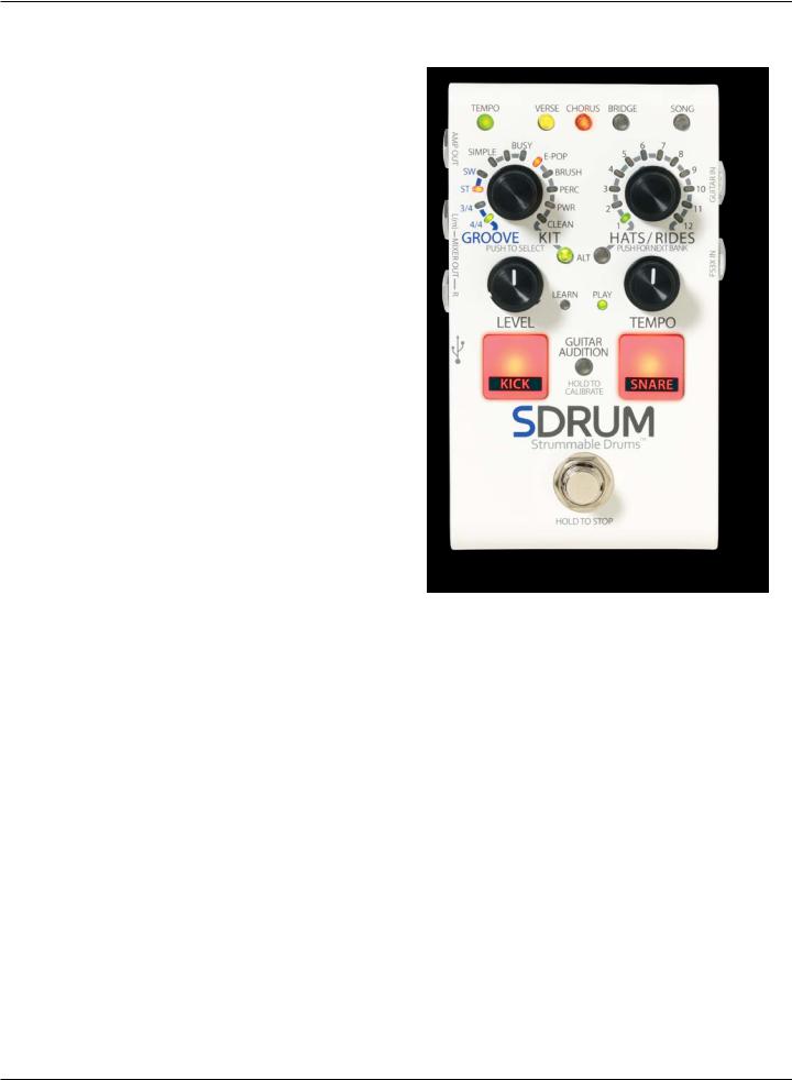
Thanks for choosing the DigiTech® SDRUM™ Strummable Drums™ Pedal. The SDRUM is the world’s first intelligent drum machine for guitarists and bassists. The SDRUM provides a quick, fun way to create professional-sounding drum patterns for practice sessions, exploring song ideas, recording, and performing.
There are two ways to create drum patterns with the SDRUM: using the pads or using BeatScratch™, a proprietary technology that allows kick/snare patterns to be created by simply scratching the upper and lower strings of an electric guitar, acoustic guitar (with pickup), or bass. This allows the SDRUM to learn drum patterns using a method commonly used by guitar and bass players to explain a beat to a drummer.
Once a kick/snare pattern is created, the "righthand" drum element (hi-hat, ride, tom, etc.) is automatically added to complement the drum pattern. The right-hand drum element can then be further edited to suit the song.
The SDRUM can learn up to 3 parts per song and store up to 36 songs. Each song and part have various settings that can be adjusted at any time. These include time signature, feel (straight or swing), embellishment amount (how busy the part is), part intensity, tempo, and more.
The SDRUM's drum sounds, from RealiTone™ and Digital Sound Factory®, incorporate samples using multiple velocity layers, for realistic dynamic expression. Tasteful random beat variations, added ghost notes, and humanization keep the drums interesting and provide the feel of a true performance.
The SDRUM offers five drum kits to select from, covering a wide range of genres. Alternate kick/snare sounds are also available for each kit. The drums are internally processed with Lexicon® reverb, so reverb tails decay naturally and are never cut off. All of this means that the SDRUM can generate drum tracks that sound very natural, powerful, organic, and authentic—all with minimal effort and time spent.
1

Features
Features
•High-quality drum samples with multiple velocity layers, humanization, and minor variations for musical and realistic drum patterns
•5 drum kits to choose from: E-Pop, Brush, Percussion, Power, and Clean
•Alternate kick and snare sounds for each drum kit
•Select between hi-hat or ride patterns, or select toms, shakers, or other percussion
•Legendary Lexicon™ reverb internally applied to drums
•Select between 3/4 or 4/4 time signatures
•Change the feel (straight or swing) and embellishment amount (simple to busy) for each drum pattern
•Proprietary BeatScratch™ technology allows kick/snare drum patterns to be created by scratching the guitar or bass strings
•Kick and snare pads provide a conventional method for teaching drum patterns
•Adjustable tempo using the variable control or tap tempo
•Built-in metronome and drumstick count-in
•Create up to 3 song parts (verse, chorus, and bridge) and switch between them during playback using the built-in footswitch
•Selectable intensity for each song part for enhanced song dynamics
•Storage for up to 36 songs
•Drum output level control
•1/4" mono or stereo mixer outputs
•1/4" amp output
•JamSync™ support for playback synchronization with compatible DigiTech JamMan® Loopers
•SilentClear™ feature prevents moments of brief playback when clearing song parts or songs
•Support for an external DigiTech FS3X Footswitch (optional), with 3 modes of operation
•Soft-touch vacuum-style footswitch
•Included power adapter
Quick Start
To get up and running quickly with the SDRUM, see the SDRUM Quick Start Guide that was included in the box or visit http://digitech.com/en-US/products/sdrum#documentation.
2

Connectors and User Interface
Connectors and User Interface
Connectors |
1 |
2 |
|
3
4 |
|
|
|
|
|
6 |
|
|
|
|
|
||
|
|
|
|
|
7 |
|
|
|
|
|
|
||
|
|
|
|
|
||
|
|
|
|
|
||
5 |
|
|
|
|
|
|
|
|
|
|
|
|
|
|
|
|
|
|
|
1.POWER INPUT Jack
Connect only the included HARMAN power adapter to this jack. See 'Specifications' on page 36 for power adapter information.
2.JAMSYNC OUT Jack
Connect this jack to DigiTech JamSync-compatible loopers to use them with the SDRUM. See 'Using JamSync' on page 31 for more information.
3.AMP OUT Jack
Connect this output to the input of the guitar or bass amplifier, or connect it to the input of an effects chain if used. Note that the output jacks are auto-sensing and output functionality will change depending on the outputs connected. See 'Output Jack Operation' on page 10 for more information.
4.MIXER L/R OUT Jacks
Connect these outputs to the line inputs of a mixer. Note that the output jacks are auto-sensing and output functionality will change depending on the outputs connected. See 'Output Jack Operation' on page 10 for more information.
5.USB Port
This Mini USB port is used for updating the SDRUM's firmware. See 'Updating Firmware' on page 35 for more information.
6.GUITAR IN Jack
Connect your guitar to this jack using an unbalanced (TS) instrument cable.
7.FS3X IN Jack
Connect an optional DigiTech FS3X Footswitch to this jack for additional hands-free control. See 'Using an FS3X Footswitch' on page 33 for more information.
3

|
|
Connectors and User Interface |
||||||||||||||||||||||
|
|
|
|
|
|
|
|
|
|
|
|
|
|
|
|
|
|
|
|
|
|
|
|
|
User Interface |
1 |
|
|
|
|
|
|
|
|
|
|
|
|
|||||||||||
|
|
|
|
|
|
|
|
|
|
|
|
|
|
|||||||||||
2 |
|
|
|
|
|
|
|
|
|
|
|
|
|
|
|
|
|
|
|
|
8 |
|||
|
|
|
|
|
|
|
|
|
|
|
|
|
|
|
|
|
|
|
|
|||||
|
|
|
|
|
|
|
|
|
|
|
|
|
|
|
|
|
|
|
|
|||||
|
|
|
|
|||||||||||||||||||||
3 |
|
|
|
|
|
|
|
|
|
|
|
|
|
|
|
|
|
|
|
|
9 |
|||
|
|
|||||||||||||||||||||||
|
|
|
|
|
|
|
|
|
|
|
|
|
|
|
|
|
|
|
|
|
|
|
|
|
4 |
|
|
|
|
|
|
|
|
|
|
|
|
|
|
|
|
|
|
|
10 |
||||
|
|
|
|
|
|
|
|
|
|
|||||||||||||||
5 |
|
|
|
|
|
|
|
|
|
|
|
|
|
|
|
|
|
|
|
|
|
|
|
11 |
|
|
|
|
|
|
|
|
|
|
|
|
|
|
|
|
|
|
|
|
|
|
|||
6 |
|
|
|
|
|
|
|
|
|
|
|
|
|
|
|
|
12 |
|||||||
|
|
|
|
|
|
|
|
|
|
|
|
|
|
|
||||||||||
7 |
|
|
|
|
|
|
|
|
|
|
|
|
|
|
|
|
|
|
|
|
|
|
|
13 |
|
|
|
|
|
|
|
|
|
|
|
|
|
|
|
|
|
|
|
|
|
|
|
||
|
|
|
|
|
|
|
|
|
|
|
|
|
|
|
|
|
|
|
|
|
|
|
||
|
|
|
|
|
|
|
|
|
||||||||||||||||
|
|
|
|
|
||||||||||||||||||||
|
|
|
|
|
|
|
|
|
|
|
|
|
|
|
|
|
|
|
|
|
|
14 |
||
|
|
|
|
|
|
|
|
|
|
|||||||||||||||
1.VERSE/CHORUS/BRIDGE PART Buttons
These PART buttons provide access to the three parts that make up a song, and they serve the following functions:
•Select a Part – Press the PART buttons to switch between each of the three song parts.
•Change Part Intensity – Once a part is selected, repeatedly press the selected PART button to cycle between the available part intensities (or how loud the part will be played). See 'Changing Song Part Intensities' on page 22 for more information.
•Enable the Metronome or Count-In Feature – When playback is stopped, press and hold the currently selected PART button to enable the metronome (when the selected song part is empty) or count-in feature (when the selected song part contains a drum pattern).
The PART buttons have the following states:
•LED Off – The part has not been learned and is not selected.
•LED Solid Dim (Green, Amber, or Red) – With an empty song selected (SONG LED off), this state indicates that the part will be automatically created. For example, when a song is cleared, the VERSE LED will light solid bright amber and the CHORUS LED will light solid dim red, indicating that teaching the verse will automatically create a chorus part. When a non-empty song is selected (SONG LED dim), this state indicates that the part has been learned but is not selected.
•LED Solid Bright (Green, Amber, or Red) – The part is selected.
•LED Flashing (Green, Amber, or Red) – The part has been learned, is selected, and the count-in feature is enabled. The rate of flashing indicates the current tempo of the song. When a part is cleared, the PART button will flash red briefly. When a song is cleared, all three PART buttons will flash red briefly. When a part or song is restored via an undo operation, the buttons will briefly flash green.
4

Connectors and User Interface
2.TEMPO Button
The TEMPO button provides the following functions:
•Tempo Indication – When a song part is empty and the metronome is on, or if a song part is not empty, the TEMPO LED will flash at the rate of the current song tempo. The TEMPO LED will light red for the first beat of the bar (during playback), dim green for the subsequent beats, then bright green for the subsequent beats of the last bar. If the tempo of a song is changed, the subsequent beats will light amber instead of green to indicate the change. Note that the TEMPO button can be pressed and held to store the new tempo of the song.
•Metronome – With an empty part selected, press and hold the TEMPO button for ~2 seconds to turn the metronome on or off. See 'Using the Metronome' on page 11 for more information.
•Tap Tempo – Tap the TEMPO button at the rate of the desired tempo to change the tempo of a song.
•Update Nominal Tempo – If the tempo of a song is altered using the TEMPO button or TEMPO knob, it will not be automatically stored to the song. To store the updated tempo, press and hold the TEMPO button for ~2 seconds. This will store the new tempo setting as the nominal (center detent TEMPO knob) setting.
See 'Adjusting the Tempo' on page 21 for more information.
3.GROOVE/KIT Encoder
Turn then press this encoder to change the drum timing, feel, embellishment amount, and kit. The following options are available:
•Timing – The first two settings select between 3/4 or 4/4 time signatures.
•Feel – The next two settings select between a straight (ST) or swing (SW) feel.
•Embellishment Amount – The next three LEDs select how simple or busy the drum part will be.
•Kit – The remaining LEDs select between the five available drum kits. See 'Selecting the Drum Kit' on page 17 for more information.
4.ALT Button (Kick/Snare)
Press this button to select alternate voicings for the kick and snare:
•LED Off – Standard Voicing
•LED Green – Alternate Voicing
The alternate voicings are different for each drum kit. See 'Selecting Alternate Sounds for the Kick/Snare' on page 18 for more information.
5.LEVEL Knob
This knob adjusts the output level of the drums. Adjust this knob to match the level of the drums to the guitar.
6.LEARN LED
This LED indicates the following functionality:
•Slowly Flashing Red – Indicates an empty song part is selected.
•Rapidly Flashing Red – Indicates the SDRUM is armed for learning and will begin learning the drum pattern once the KICK/SNARE pads are played, the guitar is scratched, or the FOOTSWITCH is pressed.
•Solid Red – Indicates the SDRUM is learning the drum pattern.
5

Connectors and User Interface
7.KICK/SNARE Pads
When the SDRUM is armed to learn, tapping these pads provides a traditional method for teaching drum patterns. They can also be used when using the SDRUM with an instrument that doesn't have a pickup. See
'Teaching Drum Patterns with the Kick and Snare Pads' on page 12 for more information.
8.SONG Button
Press this button and turn the HATS/RIDES encoder to select a different song. Song selections are displayed on the LEDs surrounding the HATS/RIDES encoder. Turn the HATS/RIDES encoder to select a song from one of the three banks (green, amber or red LEDs), then press the SONG button or HATS/RIDES encoder to load the song. See 'Managing Songs' on page 24 for more information on creating, loading, and copying songs.
9.HATS/RIDES Encoder
Turn this encoder to select a different variation on how the right-hand drum element is played. Press this encoder to select between different sub-beat timing options for the right-hand drum element. See 'Selecting Right-Hand Drum Elements' on page 19 for more information on the available options and using the HATS/RIDES encoder.
10.ALT Button (Hats/Rides)
Press this button to select alternate voicings for the right-hand drum element:
•LED Off – Standard Voicing
•LED Green – Alternate Voicing 1
•LED Red – Alternate Voicing 2
The alternate voicings are different for each drum kit. See 'Selecting Alternate Sounds for Right-Hand Drum Elements' on page 20 for more information.
11.TEMPO Knob
Turn this knob to change the tempo of the song. The tempo range is from half-speed (fully counterclockwise) to double speed (fully clockwise). To store the changed tempo of a song, press and hold the TEMPO button for ~2 seconds. The center detent position of the TEMPO knob represents the tempo stored to a song.
NOTE: Whenever the tempo is changed without directly using the TEMPO knob—for example, when teaching a new drum pattern, loading a new song, or using tap tempo—the TEMPO knob may need to be moved back to the center detent position before it becomes active again. This prevents sudden tempo changes if the knob is nudged when the current position does not match the current tempo.
See 'Adjusting Tempo Using the Tempo Knob' on page 21 for more information.
12.PLAY LED
This LED indicates the following functionality:
•LED Off – Indicates the selected song part is empty.
•LED Dim Green – Indicates the selected song part contains a drum pattern and playback is stopped.
•LED Bright Green – Indicates the SDRUM is playing the song.
•LED Flashing – The PLAY LED flashes along with the KICK and SNARE pads when the FOOTSWITCH is held down to stop playback.
6

Connectors and User Interface
13.GUITAR AUDITION Button
Press this button to cycle through the Guitar Audition modes. Press and hold this button to calibrate BeatScratch for a guitar (see 'Teaching Drum Patterns with a Guitar or Bass' on page 13 for more information on calibrating BeatScratch). This button has three states:
•Off (LED Off) – The guitar will be heard when played.
•Hybrid (LED Dim) – When an empty song part is selected, kick/snare sounds will be heard when scratching the guitar so that BeatScratch can be used. When a song part that contains a drum pattern is selected, the guitar will be heard when played so that you can play along with the drums.
•On (LED Bright) – Kick/snare sounds will always be heard when scratching the guitar.
NOTE: The Guitar Audition feature will be automatically enabled (LED bright) after calibrating BeatScratch. After creating a drum pattern, the Guitar Audition feature will be automatically set to "Hybrid" mode (LED dim).
14.FOOTSWITCH
This footswitch provides the following functions:
•Arm for Learning – When an empty song part is selected, press the FOOTSWITCH once to arm the SDRUM to learn a new drum pattern (LEARN LED will flash rapidly). Play the part, or press the FOOTSWITCH again to force the SDRUM to begin learning the new drum pattern.
•Start Playback – When playback is stopped and a song part is learned and selected, press the FOOTSWITCH once to begin song playback.
•Stop Playback – During playback, press and hold the FOOTSWITCH for ~2 seconds (or until the KICK and SNARE pads begin flashing rapidly) to stop playback. Release the FOOTSWITCH as soon as the KICK and SNARE pads begin flashing to stop the song without a sustaining crash cymbal. Continue holding the FOOTSWITCH to end a song with a sustaining crash cymbal. Note that the cymbal crash will decay naturally until the FOOTSWITCH is released or the sustain rings out.
•Clear a Part and Undo – When playback is stopped, press and hold the FOOTSWITCH for ~2 seconds
(or until the selected PART button begins to flash rapidly), then release. The selected song part will now be empty. Immediately press and hold the FOOTSWITCH again for ~2 seconds to restore the cleared part.
•Clear a Song and Undo – When playback is stopped, press and hold the FOOTSWITCH for ~4 seconds (or until all PART buttons begin to flash rapidly), then release. All parts of the song will now be empty. Immediately press and hold the FOOTSWITCH again for ~2 seconds to restore the cleared song.
NOTE: The currently selected part will be cleared first when clearing a song, but as long as the FOOTSWITCH continues to be held, then all song parts will be cleared at once.
7
Connection Diagrams
Connection Diagrams
Amplifier Setup
IN |
HARMAN |
PS0913DC (9VDC) |
|
|
Power Adapter |
Amp |
|
|
OUT |
|
UNBALANCED TS CABLES |
OUT |
|
|
IN |
IN |
|
IN |
TRS CABLE |
Guitar Effects |
|
|
FS3X Footswitch
Optional
NOTE: When only the AMP OUT jack is used, the drum signal will be processed to make the drums sound better when played through a guitar amp. See 'Output Jack Operation' on page 10 for more information.
If using guitar effects and/or a looper in this type of application, they should be placed before the SDRUM so they do not affect the drum signal. Note that the effects may need to be bypassed to use BeatScratch.
Mixer Setup
HARMAN
 PS0913DC (9VDC)
Power Adapter
|
|
IN |
|
|
|
OUT |
|
|
|
IN |
TRS CABLE |
|
UNBALANCED TS OR |
OUT |
|
|
|
|
|
IN |
BALANCED TRS CABLES |
|
|
Mixer |
|
|
FS3X Footswitch
Optional
NOTE: When only the MIXER OUT jacks are used, the mono guitar signal and stereo drum signal are fed to the MIXER OUT jacks. This setup works well for applications where an acoustic guitar with a pickup or a bass guitar are connected to a live PA system. See 'Output Jack Operation' on page 10 for more information.
8

Connection Diagrams
Amplifier + Mixer Setup
IN |
HARMAN |
PS0913DC (9VDC) |
|
|
Power Adapter |
Amp
UNBALANCED TS CABLES
OUT |
IN |
OUT |
|
Guitar Effects |
OUT |
|
|
|
UNBALANCED TS OR |
OUT |
|
|
|
IN |
BALANCED TRS CABLES |
|
Mixer |
|
IN
|
|
|
|
|
|
|
|
|
IN |
|
TRS CABLE |
|
|||||
|
|
|
|
|
|
|
|
|
|
|
|
|
|
|
|
|
|
|
|
|
|
|
|
|
|
|
|
|
|
|
|
|
|
|
|
FS3X Footswitch
Optional
NOTE: When connected to both the MIXER and AMP OUT jacks, the guitar signal will be fed to the AMP OUT jack and the drum signal will be fed to the MIXER OUT jacks. See 'Output Jack Operation' on page 10 for more information. If using guitar effects, they can be placed before the SDRUM or between the SDRUM and amp in this type of application. Note that if the effects are placed before the SDRUM, they may need to be bypassed to use BeatScratch.
JamSync Setup
|
Amp |
|
|
HARMAN |
|
IN |
PS0913DC (9VDC) |
IN |
|
Power Adapter |
|
|
OUT |
IN |
|
OUT |
|
|
OUT |
|
|
|
IN |
|
|
|
OUT |
Looper |
|
|
IN |
w/JamSync |
|
UNBALANCED TS OR |
OUT |
TRS CABLE |
|
|
||
IN |
BALANCED TRS CABLES |
|
|
Mixer |
|
|
FS3X Footswitch
Optional
NOTE: The looper should be placed before the SDRUM in most cases, such as when using only the AMP OUT jack. if using the AMP and MIXER OUT jacks, the looper can also be placed between the SDRUM and amp if desired. See 'Using JamSync' on page 31 for information on using the SDRUM in a JamSync setup.
9
Output Jack Operation
Output Jack Operation
The output jacks have an auto-sensing feature that allows the SDRUM to automatically optimize the outputs for the application. The table below describes how the SDRUM will operate depending on which outputs are connected.
AMP OUT |
MIXER OUT |
|
Jack |
Jacks |
Operation Description |
Connected |
Connected |
|
|
|
|
|
|
A mono mix of the guitar and drum signal will be sent to the AMP OUT jack. |
|
|
Complementary equalization will be applied to the drum signal to make it |
|
|
sound better when played through a guitar amp. |
|
|
NOTE: When using a guitar amp to play the drums from the SDRUM, set |
|
|
the amp to run as cleanly as possible in order to avoid distorting the drums. |
|
|
The drums are pre-EQ'd to sound best through a clean amp with "flat" EQ |
|
|
settings. If using guitar effects and/or a looper, they should be placed before |
|
|
the SDRUM when using only the AMP OUT jack. |
|
|
|
|
|
The drum and guitar signals will be mixed and sent to the MIXER OUT jacks. |
|
|
If only the left (mono) MIXER OUT jack is connected, the guitar/drum mix |
|
|
will be mono. If the left and right MIXER OUT jacks are connected, the guitar |
|
|
signal will be mono and the drum signal will be stereo. |
|
|
NOTE: The SDRUM does not apply cabinet simulation to the guitar signal. |
|
|
This allows an acoustic or bass guitar to be used when only the MIXER OUT |
|
|
jacks are connected. |
|
|
|
|
|
The guitar signal will be fed to the AMP OUT jack only. The drum signal will |
|
|
be sent to the MIXER OUT jacks in mono (if only the MIXER OUT L jack is |
|
|
used) or stereo (if both MIXER OUT jacks are used). If using guitar effects and/ |
|
|
or a looper, they can be placed before or after the SDRUM when using both |
|
|
the AMP OUT and MIXER OUT jacks. |
|
|
|
Making Connections and Applying Power
To connect the SDRUM pedal:
1.Turn down the guitar amp. If connecting to a mixer, turn down the gain/trim controls and lower the faders on the channels to which you are connecting.
2.Make all connections to the SDRUM as shown in 'Connection Diagrams' on page 8.
3.Connect the included HARMAN power adapter to the SDRUM POWER input connector, then connect the other end to an available AC outlet and wait for the SDRUM to boot.
4.Turn the guitar volume all the way up, strum the guitar, and then gradually increase the guitar amp volume until the desired level is achieved. If using a mixer, set the channel faders to unity (0), then raise the gain/ trim controls while tapping the KICK/SNARE pads for the desired level. Set the LEVEL knob to 12 o'clock.
10
 Loading...