


AMP
MODELING
PICKUP
MODELING
ACOUSTIC
MODELING
CABINET
MODELING
EFFECTS
TALKER™
RHYTHM
TRAINER
LEARN-A-LICK™
 MODELING GUITAR EFFECT SYSTEM
USER’S
GUIDE
DIGITAL OUTPUT
These symbols are internationally accepted symbols that warn of potential hazards with electrical products.The lightning flash means that there are dangerous voltages present within the unit.The exclamation point indicates that it is necessary for the user to refer to the owners manual.
These symbols warn that there are no user serviceable parts inside the unit. Do not open the unit. Do not attempt to service the unit yourself. Refer all servicing to qualified personnel. Opening the chassis for any reason will void the manufacturer’s warranty. Do not get the unit wet. If liquid is spilled on the unit, shut it off immediately and take it to a dealer for service.
Disconnect the unit during storms to prevent damage.
U.K. Mains Plug Warning
A molded mains plug that has been cut off from the cord is unsafe. Discard the mains plug at a suitable facility. Never under any circumstances should you insert a damaged or cut mains plug into a 13 amp power socket. Do not use the mains plug without the fuse cover in place. Replacement fuse covers can be obtained from your local retailer. Replacement fuses are 13 amps and MUST be ASTA approved to BS1362.
Warning
For your protection, please read the following:
Water and Moisture: Appliances should not be used near water (e.g. near a bathtub, washbowl, kitchen sink, laundry tub, in a wet basement, or near a swimming pool, etc.) Care should be taken so that objects do not fall and liquids are not spilled into the enclosure through openings.
Power Sources: The appliance should be connected to a power supply only of the type described in the operating instructions or as marked on the appliance.
Grounding or Polarization: Precautions should be taken so that the grounding or polarization means of an appliance is not defeated.
Power Cord Protection: Power supply cords should be routed so that they are not likely to be walked on or pinched by items placed upon or against them, paying particular attention to cords at plugs, convenience receptacles, and the point where they exit from the appliance.
Servicing: To reduce the risk of fire or electrical shock, the user should not attempt to service the appliance beyond that described in the operating instructions. All other servicing should be referred to qualified service personnel.
For units equipped with externally accessible fuse receptacle: Replace fuse with same type and rating only.
Safety Instructions
Notice for customers if your unit is equipped with a power cord.
Warning:This appliance must be earthed.
The cores in the mains lead are colored in accordance with the following code:
Green and Yellow - Earth Blue - Neutral Brown - Live
As colors of the cores in the mains lead of this appliance may not correspond with the colored markings identifying the terminals in your plug, proceed as follows:
•The core which is colored green and yellow must be connected to the terminal in the plug marked with the letter E, or with the earth symbol, or colored green, or green and yellow.
•The core which is colored blue must be connected to the terminal marked N, or colored black.
•The core which is colored brown must be connected to the terminal marked L, or colored red.
This equipment may require the use of a different line cord, attachment plug, or both, depending on the available power source at installation. If the attachment plug needs to be changed, refer servicing to qualified service personnel who should refer to the table below.The green/yellow wire shall be connected directly to the unit’s chassis.
CONDUCTOR |
WIRE COLOR |
|||
Normal |
Alt |
|||
|
|
|||
L |
LIVE |
BROWN |
BLACK |
|
N |
NEUTRAL |
BLUE |
WHITE |
|
E |
EARTH GND |
GREEN/YEL |
GREEN |
|
Warning: If the ground plug is defeated, certain fault conditions in the unit or in the system to which it is connected can result in full line voltage between chassis and earth ground. Severe injury or death can then result if the chassis and earth ground are touched simultaneously.
Electromagnetic Compatibility
Operation is subject to the following conditions: •This device may not cause harmful interference.
•This device must accept any interference received, including interference that may cause undesired operation.
•Use only shielded interconnecting cables.
•Operation of this unit within significant electromagnetic fields should be avoided.
I

|
DECLARATION OF CONFORMITY |
Manufacturer’s Name: |
Digitech Electronics |
Manufacturer’s Address: |
8760 S. Sandy Parkway |
|
Sandy, Utah 84070, USA |
declares that the product: |
RP2000 |
Product Name: |
|
Product Options: |
All (requires a Class II power adapter that conforms to the requirements of |
|
EN60065, EN60742, or equivalent.) |
conforms to the following Product Specifications: |
|
Safety: |
EN 60065 (1993) |
|
IEC 65 (1985) with Amendments 1, 2 & 3 |
EMC: |
EN 55013 (1990) |
|
EN 55020 (1991) |
Supplementary Information:
The product herewith complies with the requirements of the Low Voltage Directive 73/23/EEC and EMC
Directive 89/336/EEC as amended by Directive 93/68/EEC.
Digitech
Vice-President of Engineering
8760 S. Sandy Parkway
Sandy, Utah 84070, USA
Tel: 801-566-8800
Fax: 801-566-7005
Effective October 8, 1999
European Contact: Your Local Digitech Sales and Service Office or
Harman Music Group
8760 S. Sandy Parkway
Sandy, Utah 84070, USA
Tel. 801-568-7638
Fax 801-568-7642
Warranty
We at Digitech are very proud of our products and back-up each one we sell with the following warranty:
1.The warranty registration card must be mailed within ten days after purchase date to validate this warranty.
2.Digitech warrants this product, when used solely within the U.S., to be free from defects in materials and workmanship under normal use and service.
3.Digitech liability under this warranty is limited to repairing or replacing defective materials that show evidence of defect, pro-
vided the product is returned to Digitech WITH RETURN AUTHORIZATION, where all parts and labor will be covered up to a period of one year. A Return Authorization number may be obtained from Digitech by telephone.The company shall not be liable for any consequential damage as a result of the product's use in any circuit or assembly.
4.Proof-of-purchase is considered to be the burden of the consumer.
5.Digitech reserves the right to make changes in design, or make additions to, or improvements upon this product without incurring any obligation to install the same on products previously manufactured.
6.The consumer forfeits the benefits of this warranty if the product's main assembly is opened and tampered with by anyone other than a certified Digitech technician or, if the product is used with AC voltages outside of the range suggested by the manufacturer.
7.The foregoing is in lieu of all other warranties, expressed or implied, and Digitech neither assumes nor authorizes any person to assume any obligation or liability in connection with the sale of this product. In no event shall Digitech or its dealers be liable for special or consequential damages or from any delay in the performance of this warranty due to causes beyond their control.
NOTE:The information contained in this manual is subject to change at any time without notification. Some information contained in this manual may also be inaccurate due to undocumented changes in the product or operating system since this version of the manual was completed.The information contained in this version of the owner's manual supersedes all previous versions.
II
Table of Contents |
|
Safety Information .................................................................................. |
I |
Declaration of Conformity .................................................................. |
II |
Warranty .................................................................................................. |
II |
Table of Contents .................................................................................. |
III |
Section One - Introduction |
|
Getting Acquainted ................................................................................ |
1 |
Included Items ........................................................................................ |
1 |
Quick Start .............................................................................................. |
1 |
A Guided Tour of the RP2000 ............................................................ |
2 |
The Front Panel .................................................................................. |
2 |
The Rear Panel .................................................................................. |
4 |
Getting Started........................................................................................ |
5 |
Making Connections .............................................................................. |
5 |
Mono .................................................................................................... |
5 |
Stereo .................................................................................................. |
5 |
Direct to a Mixing Console ............................................................ |
6 |
S/PDIF Digital Output ...................................................................... |
6 |
Applying Power ...................................................................................... |
6 |
About the RP2000.................................................................................. |
7 |
The Presets .............................................................................................. |
7 |
Performance Mode ................................................................................ |
7 |
Preset Mode ........................................................................................ |
7 |
FX Mode .............................................................................................. |
7 |
The Footswitches .................................................................................. |
7 |
The Expression Pedal ............................................................................ |
8 |
Bypass Mode ............................................................................................ |
8 |
Tuner Mode.............................................................................................. |
8 |
Edit Mode ................................................................................................ |
9 |
Rhythm Mode .......................................................................................... |
9 |
Store Mode .............................................................................................. |
9 |
Utility Mode ............................................................................................ |
9 |
Assign Mode ............................................................................................ |
9 |
Learn-A-Lick Mode ................................................................................ |
10 |
Using Learn-A-Lick ............................................................................ |
10 |
Jam-A-Long .............................................................................................. |
10 |
Section Two - Editing Functions |
|
Editing/Creating Presets ........................................................................ |
11 |
The Matrix................................................................................................ |
11 |
Storing/Copying a Preset ...................................................................... |
12 |
Section Three - Effects and Parameters
About the Effects .................................................................................... |
13 |
Effects Definitions .................................................................................. |
13 |
Pickup Simulator ................................................................................ |
13 |
Compressor ........................................................................................ |
13 |
Wah/Pitch ............................................................................................ |
14 |
WahWah ........................................................................................ |
14 |
Pitch .............................................................................................. |
14 |
Detune ............................................................................................ |
14 |
Whammy ........................................................................................ |
14 |
Harmony ........................................................................................ |
15 |
Amp Modeling .................................................................................... |
15 |
Cabinet Modeling .............................................................................. |
16 |
EQ.......................................................................................................... |
16 |
Talker™ ................................................................................................ |
17 |
Noise Gate .......................................................................................... |
17 |
Effects.................................................................................................... |
17 |
Chorus ............................................................................................ |
18 |
Flanger ............................................................................................ |
18 |
Phaser .............................................................................................. |
18 |
Tremolo .......................................................................................... |
18 |
Panner.............................................................................................. |
19 |
Vibrato ............................................................................................ |
19 |
Rotary.............................................................................................. |
19 |
AutoYah™ ...................................................................................... |
19 |
YahYah™ ........................................................................................ |
19 |
Envelope Filter .............................................................................. |
20 |
Detuner .......................................................................................... |
20 |
Pitch Shifting .................................................................................. |
20 |
Delay .................................................................................................... |
20 |
Reverb .................................................................................................. |
21 |
Volume .................................................................................................. |
21 |
Section Four - Tutorial |
|
Guided Example ...................................................................................... |
22 |
Choose a Program ................................................................................ |
22 |
Enter Edit Mode...................................................................................... |
22 |
Select Pickup Type .................................................................................. |
22 |
Turn the Compressor Off .................................................................... |
22 |
Select Classic Wah.................................................................................. |
22 |
Select the Green Channel Amp Model ............................................ |
23 |
Adjust the Green Channel .................................................................. |
23 |
Select the Red Channel Amp Model.................................................. |
24 |
Adjust the EQ.......................................................................................... |
24 |
Adjust the Noise Gate .......................................................................... |
25 |
Select Phaser............................................................................................ |
25 |
Turn Delay Off ........................................................................................ |
26 |
Adjust the Reverb .................................................................................. |
26 |
Set the Preset Level .............................................................................. |
26 |
Store the Preset...................................................................................... |
27 |
Section Five - Other Functions |
|
Rhythm ...................................................................................................... |
28 |
Pattern .................................................................................................. |
28 |
Tempo .................................................................................................. |
28 |
Level ...................................................................................................... |
28 |
Assign ........................................................................................................ |
28 |
Expression Pedal ................................................................................ |
29 |
Control Switch .................................................................................. |
29 |
LFO1 and LFO2.................................................................................. |
30 |
Utilities ...................................................................................................... |
30 |
Mono/Stereo Output ........................................................................ |
30 |
Global Cabinet Modeling.................................................................. |
31 |
V-Switch Sensitivity ............................................................................ |
31 |
Volume Pedal Update ........................................................................ |
31 |
Dry Track ............................................................................................ |
31 |
Bank Name .......................................................................................... |
31 |
MIDI Channel...................................................................................... |
32 |
MIDI Bulk Dump ................................................................................ |
32 |
MIDI Preset Dump ............................................................................ |
32 |
MIDI Mapping...................................................................................... |
32 |
MIDI Merge ........................................................................................ |
33 |
Expression Pedal Calibration .......................................................... |
33 |
Factory Reset...................................................................................... |
33 |
Section Six - Appendix |
|
Factory Preset List ................................................................................ |
34 |
MIDI CC List .......................................................................................... |
35 |
MIDI Implementation ............................................................................ |
36 |
Specifications............................................................................................ |
37 |
III

Section One - Introduction
Section-1 Introduction
Getting Acquainted
Congratulations on your wise choice in purchasing the RP2000.Thanks to the continuous advances in musical technology, you have the flexibility, power, and capability of producing sonic creations never before thought possible. Although the RP2000 is so user friendly you may not even need to read this manual, we recommend that you become better acquainted with us, and what we have to offer by going through this User’s Guide with your RP2000 in front of you. It is your key to unlocking the potential within the RP2000.
Included Items
Before you get started, please make sure that the following items have been included:
•RP2000
•PS0920 Power Supply
•User’s Guide
•Warranty Card
The utmost care was taken while your RP2000 was being manufactured, so everything should be included and in perfect working order. If anything is missing, contact the factory at once. Please help us become acquainted with you and your needs by completing your warranty card. It is your safeguard should a problem arise with your RP2000.
Quick Start
This brief overview of the RP2000 and it’s functions is included for those of you looking for immediate gratification.
Making Connections:
Connect your instrument to the input jack on the rear panel. Connect the Left or Right Outputs to the input(s) of your amplifier(s) or power amp.To select the output mode, press the Utility button once and rotate the Data Wheel to select either Stereo or Mono output mode.
Apply Power:
Turn the Output knob on the rear panel of the RP2000 all the way down (fully counter clockwise). Connect the plug of the PS0920 power supply to the power jack on the RP2000. Connect the other end of the PS0920 power supply to an AC outlet.Turn the power of your amplifier(s) to the on position and adjust the volume(s)to a normal playing level. Gradually increase the RP2000 Output knob to achieve the desired volume.
Select Preset:
The RP2000 comes with 64 pre-Programmed factory Presets, and 64 user Presets. From the factory, the user Presets are exact duplicates of the factory Presets.This allows you to experiment without running the risk of losing any of the original sounds contained in the RP2000.
Use the 1-4 Footswitches or the Data Wheel to select different Presets. Once you have found Presets that suit your taste, you can alter the sounds to your specific needs. By pressing the Edit button and then using the Matrix buttons, you can access any of the effects contained within the selected Preset. Successive presses of the Matrix buttons will advance through each of the parameters related to each effect. Use the LED Matrix to choose the parameter you wish to edit. Follow the rows and columns to the point where the vertical and horizontal LEDs intersect.This will indicate the parameter you have selected. Once a parameter has been selected, you may increase or decrease the parameter value to your liking by rotating the Data Wheel. Remember that you are not at risk of losing any sounds so, don’t be afraid to experiment.
Page 1


 RP2000
 User’s

 Guide
Guide

Page 2
Section One - Introduction
A Guided Tour of the RP2000
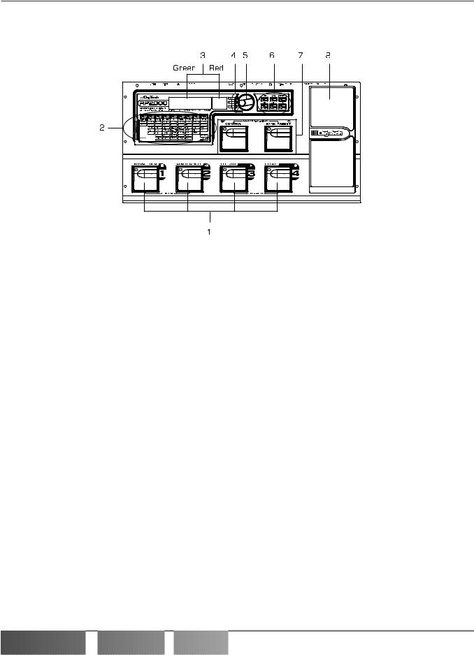
The Front Panel
1.Preset Switches - These 4 footswitches are used to select Presets, access the Tuner, turn individual effects on and off, change Amp Channels, select functions in Learn-A-Lick mode, or bypass the RP2000.
2 Matrix - The matrix provides information regarding the current Preset, and parameter edit functions.While in performance mode, the LEDs in the 9 buttons across the top of the Matrix will provide a visual indication of which effects are in use for the current Preset. Pressing these buttons will turn these effects on and off. While in Edit mode, the 9 buttons across the top of the matrix provide access to the effects and parameters in the RP2000. Successive presses of the same button will advance through all parameters associated with the selected Effect.The LEDs within each button indicate which effect has been selected, and the vertical row of LEDs will indicate the selected parameter. Following the horizontal and vertical LEDs across the matrix to the point where they intersect will indicate which effect and parameter are selected.
3. Display - The Display consists of six alphanumeric green characters, and two red digits, and provides information for several different functions depending on the mode that has been selected. In Performance mode, the green portion of the Display will show the currently selected Preset name and the red portion will show the Preset number.The Display will also show Bank names when changing banks, and momentarily flash the active Amp Channel when the Amp Channel is switched. In Edit mode, the green portion of the Display will show the status or parameter of the currently selected effect, while the red portion will show the value of the parameter. In Tuner mode, the red portion of the Display will show the note played, and the green portion will provide sharp or flat indications. In Learn-A-Lick mode, the green display shows the currently selected function and the red Display provides an elapsed time for record and playback.
4. LED Indicators - These three LEDs offer a visual indication of clipping, and whether a User or Factory Preset is active.The top LED is a clip indicator which will light when internal DSP clipping occurs.The Factory and User LEDs will light independently indicating whether a Factory or User Preset is in use.
5. Data Wheel - The Data Wheel functions will change depending upon which mode has been selected. It is used to change Presets, increase or decrease Parameter values, edit Assign and Rhythm functions, and modify utility settings.
RP2000

 User’s
 Guide
Guide


Section One - Introduction
6. Mode Buttons- These 6 buttons are used to select various modes in which the RP2000 will function.The top three buttons perform single functions while the bottom three buttons perform dual functions based upon the current operation of the RP2000.The buttons are labeled as follows:
A) FX Mode - The FX Mode button selects whether the 1-4 footswitches will recall Presets within the selected Bank, or act as on/off switches for the individual effects in the currently active Preset. The FX Mode button will light when the switches are performing effects on/off functions.
B) Edit/Exit - This button will take the RP2000 in and out of the edit mode.The LED will light while you are in Edit mode.This button can also be used to escape from any mode or level of editing.
C) Rhythm - The Rhythm button is used to access the drum loop feature in the RP2000.When the Rhythm feature is selected, the LED will light and the bottom row of Mode buttons are used to edit various functions in Rhythm mode.
D)Store - The Store button is used to save your custom edits to the user Presets.The function of this button changes to select Pattern in Rhythm mode.
E)Utility - The Utility button provides access to several global functions including MIDI Channel, and Sysex
dumps.The function of this button changes to select Tempo in Rhythm mode.
F) Assign - This button is used to assign a parameter to the Control footswitch, the Expression Pedal, or internal LFOs.The function of this button changes to select Level in Rhythm mode.
7. Bank/Control Switches - The Bank switch is used to change the RP2000’s Banks. If FX Mode is selected, it changes Presets.The Control switch can have a variety of functions assigned to it. Press these 2 footswitches simultaneously to access the Learn-A-Lick function, or individually to adjust the Learn-A-Lick playback tempo.
8. Expression Pedal - The Expression Pedal is used for real time control of parameters during performance. For Example, this pedal may control Volume in one Preset,Wah in another Preset, or control the Delay Level in yet another Preset. Individual boundaries may be set up for the minimum and maximum parameter values that are controlled by the Expression Pedal.The RP2000’s exclusive V-Switch feature allows you to change functions of the Expression Pedal by applying extra pressure on the toe of the Pedal. See page 29 for more on making expression pedal assignments.
Page 3


 RP2000
 User’s

 Guide
Guide

Section One - Introduction
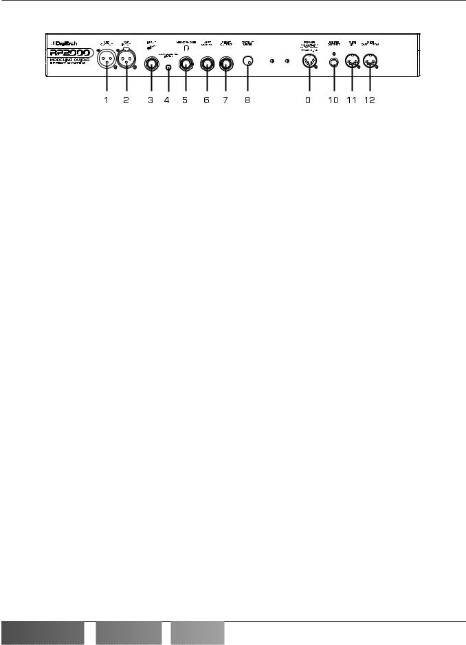
Rear Panel
Page 4
1.Mic Output - This XLR jack is used as a Mic throughput passing your Mic signal on to the house mixing console.
2.Mic Input - This XLR jack is used to connect a low impedance Mic to the RP2000 for use with the Talker, and
Vocoder effects.A mic with a cardiod pattern is recommended.
3.Input Jack - Connect your instrument to this jack.
4.Jam-A-Long Jack - This is where you connect a tape or CD player in order to jam along with the music, or for the
purpose of recording a lick into the Learn-A-Lick phrase recorder. Use an 1/8” stereo plug for this connection. See page 10 for more on using the Jam-A-Long and Learn-A-Lick function.
5. Headphone Output - Connect stereo headphones to this jack. Be sure to enable Cabinet Modeling when listening through Headphones. Do not connect a mono jack here as doing so may damage the output driver.
6.Left Output - Connect from this jack to the input of an amplifier or the left input of a stereo power amp.
7.Right Output - Use this jack in conjunction with the Left Output for stereo applications. Connect from this output
to the input of a second amplifier, or the right input of a stereo power amp.
8.Output Level - This knob controls the overall volume level of the signal coming out of the RP2000.
9.Power Input - This jack is used to power the RP2000. Use only the DigiTech PS0920 power supply provided.
10.S/PDIF Output - This is the digital output from the RP2000.The signal at this output is in a stereo digital format,
and is to be connected to a digital S/PDIF input such as those found on digital recording devices.
ATTENTION: Do not connect the S/PDIF output to analog auxiliary, CD, phono, or tape inputs on consumer electronic devices. It is not compatible with these inputs.
11. MIDI In - This jack is used to receive all incoming MIDI data intended to control the RP2000. Connect from this jack to the MIDI out of a sequencer, MIDI controller, or MIDI storage device.
12. MIDI Out/Thru - This jack is used for all MIDI data being sent out of the RP2000. Connect from this jack to the MIDI input of any external MIDI recording device for MIDI sysex dumps.The MIDI Thru function of this jack simply sends out the same information that is received at the MIDI In of the RP2000.
RP2000

 User’s
 Guide
Guide


Section One - Introduction
Getting Started
Making Connections
Before connecting the RP2000, make sure that the power to your amplifier is turned off, and that the power to the RP2000 is disconnected.There is no power switch on the RP2000.To turn the RP2000 on or off, simply connect or disconnect the power supply from an AC outlet.
There are several different connection options available when using the RP2000.You may run mono into an amp or power amp, stereo into two amps or a stereo power amp, direct into a mixing console, connect digitally to the input of a digital recorder or mixer, or a combination of these.The following diagrams show the connections for some of these options.
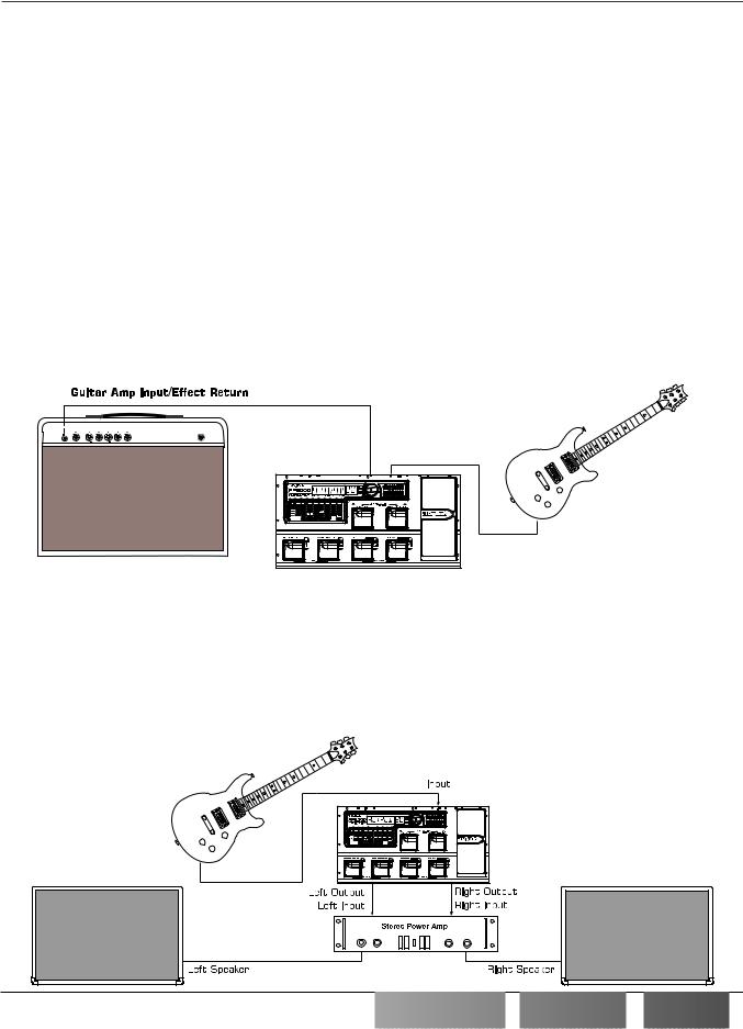
NOTE: The RP2000 is a preamp. Running The RP2000 signal into the input of a combo guitar amplifier will preamplify the signal again possibly adding noise and feedback.When using a guitar amp, it may be best to connect the guitar to the input of the RP2000 and the output of the RP2000 to the effect return of the amplifier.
Mono Operation
Connect your guitar to the input of the RP2000. Connect the Left output of the RP2000 to the instrument input on your amplifier, or to the line input of a power amp. Select Mono as the Output mode in the Utility menu. See page 30 for more on selecting the Output mode.
Page 5
Left Output
Input
Stereo Operation
For stereo operation connect the guitar to the input of the RP2000. Connect from the RP2000’s Left output to the input of one amplifier or channel of a power amp. Connect from the Right output of the RP2000 to a second amplifier, or to a second channel of a power amp. Select Stereo as the Output mode in the Utility menu. See page 30 for more on selecting the Output mode.


 RP2000
 User’s

 Guide
Guide

Page 6
Section One - Introduction
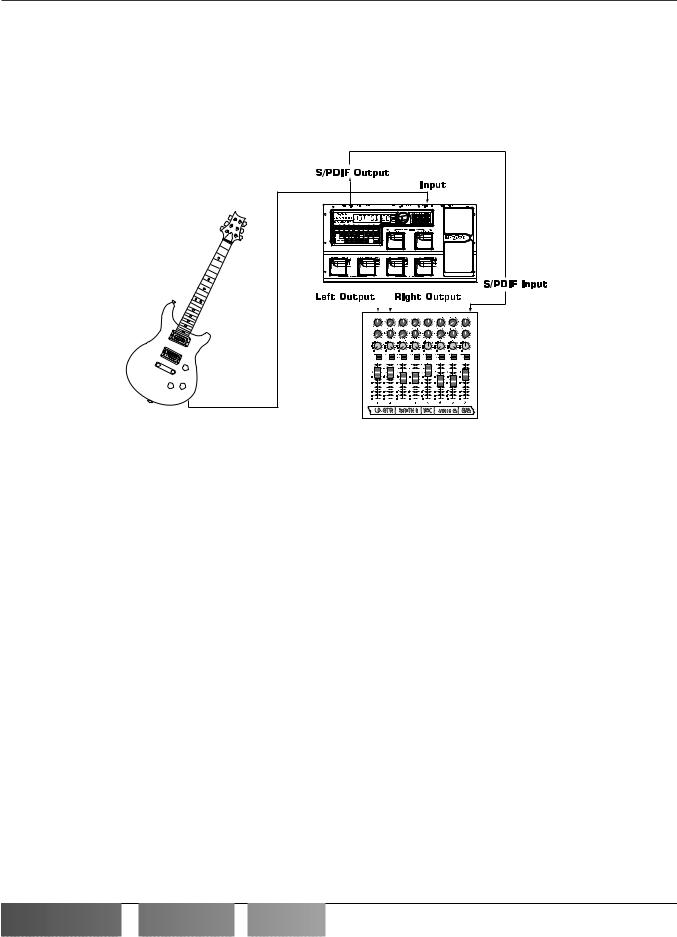
Direct to a Mixing Console
The RP2000 can be connected directly to the inputs of a house PA system, or to a recording console. Connect the guitar to the input of the RP2000. Connect from the outputs of the RP2000 to the channel inputs of the mixing console. If the RP2000 is to be used in Stereo mode, set the pan controls of the mixer hard left and right, and select stereo as the output mode in the RP2000’s Utility menu. See page 30 for more information on the output mode. Be sure to engage the RP2000’s Cabinet Emulator when connecting direct to a mixer. See page 31 for more on selecting the Cabinet Emulator.
S/PDIF Digital Output
The RP2000 includes a digital S/PDIF output enabling you to eliminate multiple A/D and D/A conversions when recording digitally. Simply connect from the S/PDIF output of the RP2000 to the S/PDIF input on your digital mixer or recorder.You must have S/PDIF inputs on the receiving device in order to use this output.You may use the analog and digital outputs of the RP2000 simultaneously. Be sure to use a 75 ohm or RCA video cable to connect from the Digital Output to a recording device.
ATTENTION: Do not connect the S/PDIF output to analog auxiliary, CD, phono, or tape inputs on consumer electronic devices. It is not compatible with these inputs.
Applying Power
Once the audio connections have been made, turn the Output Level all the way down (counterclockwise). Connect the PS0920 to the power jack on the back of the RP2000 and the other end to an AC outlet. Turn the power to your amplifier(s) on. Set the amp(s) to a clean tone and set the tone controls to a flat EQ response (on most amps, this would be 0 or 5 on the tone controls).Turn the Output Level of the RP2000 up to achieve the desired volume level.
RP2000

 User’s
 Guide
Guide


Section One - Introduction
About the RP2000
The Presets
Presets are numbered locations of programmed sounds which reside in the RP2000. Presets can be recalled with the Footswitches or the Data Wheel.The RP2000 comes with 64 Factory and 64 User Presets available.The Factory Presets will not allow you to store any changes to them.The User Presets are locations where your creations may be stored. From the factory, the 64 User Presets are exact duplicates of the 64 Factory Presets.This allows you to make your own Presets without the worry of losing any of the sounds that the RP2000 came with.
When you select a Preset, the name of the Preset will be shown in the green section of the Display and the number of the Preset will be shown in the red section of the Display. An LED to the right of the Display will light to indicate whether you are in a User Preset or a Factory Preset.
Performance Mode
When you first apply power to the RP2000, it will power up in Performance mode. Performance mode is the mode used while you are performing. From Performance mode, you have access to all of the Presets within the RP2000 with your choice of using either Preset Mode or FX Mode.
Preset Mode
While in Preset mode, the Numeric Display will show the currently selected Preset’s name and number. The horizontal LEDs on the Matrix will indicate the Effects which are active in the Preset. In Preset mode, the 1-4 Footswitches will call up different User Presets.The Data Wheel must be used to access Factory Presets.
FX Mode
FX Mode is another mode of operation which can be used during a performance.The only difference between Preset Mode and FX Mode is in the functions of the 1-4 footswitches. In FX Mode, footswitches 1-4 will turn on and off specific effects within the currently selected Preset, much the same as if you were using individual stomp box type effects.The FX Mode button (located to the right of the Data Wheel) is used to switch between Preset and FX Modes.When the button is lit, the FX mode is active.
The Footswitches
The RP2000 has 6 footswitches which can perform different functions.These functions are permanently assigned and cannot be reconfigured (except for the Control switch). In Preset Mode, Footswitches 1-4 will select Presets 1-4 in every User Bank. In FX Mode and Edit Mode, Footswitches 1-4 will will turn effects on or off and change Amp Channels within a Preset. Depending on which effects are active in the current Preset, these switches may have one or more LEDs lit, indicating the status of these effects.The Amp Channel Footswitch will light either green or red indicating whether the green or red Amp Channel is selected. In the Learn-A-Lick Mode, the 1-4 switches will activate Learn-A-Lick’s Stop, Play, Reverse, or Record functions. Pressing and holding the 1 and 2 switches simultaneously will access the Tuner mode. Pressing and holding the 3 and 4 switches simultaneously will bypass the RP2000.
Page 7


 RP2000
 User’s

 Guide
Guide


Page 8
Section One - Introduction
The Bank and Control switches are located on the upper tear. In Preset mode, the Bank switch will advance Banks with single presses or reverse Banks if held down. In FX mode, the Bank switch will advance Presets with single presses or reverse Presets if held down.The Control switch is used to control a Parameter of your choice in real time, or to change Banks. Pressing and holding the Bank and Control switches simultaneously will access Learn-A-Lick Mode.
The Expression Pedal
As you go through the different Presets in the RP2000, you will find that the expression pedal has different functions. This pedal can be assigned to control one of several different parameters in each Preset. Rocking the pedal back and forth will change the value of the assigned parameter.You can assign minimum and maximum values (stop points) for each parameter that you control with the pedal.The Expression Pedal also includes a feature called V-Switch which allows you to override the Pedal assignment. Applying extra pressure to the toe of the Expression Pedal, will enable the selected effect in the Wah/Pitch module, and the Expression Pedal’s function will change to act as the Wah or Whammy™ if one of those is the selected effect. For more on assigning the expression pedal, see page 29.
Bypass Mode
The RP2000 can be bypassed for a clean, unprocessed, straight guitar tone.To bypass the RP2000, press the footswitch representing the currently active Preset (the 1-4 footswitch that is lit).To bypass the RP2000 while in FX Mode, press the 3 and 4 footswitches simultaneously.This disengages all Modeling and effects.The Display will flash bypass and all LEDs in the Matrix will turn off while the Preset is bypassed. Pressing any footswitch will exit Bypass and return to the last Preset used. None of the Matrix or Programming buttons are available in Bypass mode.
Tuner Mode
The Tuner in the RP2000 allows you to quickly tune or check the tuning on your guitar. Enter Tuner mode by pressing and holding the 1 and 2 footswitches simultaneously.The Display will briefly show tuner indicating that you are in Tuner mode.To begin tuning, play a note on your guitar (a harmonic at the 12th fret usually works best).The red display window will show the note being played, and the green section of the display will indicate whether you are sharp or flat. Arrows to the left indicate the note is sharp and should be tuned down. Arrows to the right indicate the note is flat and should be tuned up.When your note is in tune, the Display will show --><--.
In Tuner mode, you can change your tuning reference by rotating the Data Wheel when ref is showing in the Display. The default factory setting is :A=440 Hz.The tuning reference ranges from 427 Hz to 453 Hz, which is the equivalent of ± 50 cents (1/2 semitone) in either direction from 440 Hz.When you scroll down from 427 Hz, you will also find alternate dropped tunings. Alternate tunings are A = Ab (415),A = G (392), and A = Gb (369).The display window will briefly flash the currently selected tuning preference.
Exit tuner mode by pressing any of the footswitches.
RP2000

 User’s
 Guide
Guide


Section One - Introduction
Edit Mode
The Edit Mode of the RP2000 allows you to customize Presets to suit your particular needs and applications. Pressing the Edit/Exit button allows you to access, replace, or change any aspects of the effects which make up the Preset. Once in the Edit mode, the buttons in the matrix can be used to access the effects. Successive presses of each button will advance through all parameters associated with the selected effect. Rotating the Data Wheel will change the value of the currently selected Parameter.The LED in the Edit/Exit button will light while in the Edit mode. Press the Edit/Exit button again to exit the Edit mode. See page 11 for more information on editing functions.
Rhythm Mode
The RP2000 includes several sampled drum patterns which are useful for rehearsing different riffs in an assortment of musical styles and time signatures. Pressing the Rhythm button from any mode (except for Store, Utility, and Assign modes) will enable Rhythm mode and start playback of the drum loop. If Rhythm mode is enabled from Performance mode, the Store, Utility, and Assign buttons will all light up indicating that their functionality has changed to Pattern, Tempo, and Level respectively. Pressing any of these buttons at this time will display the secondary function for 5 seconds, at which time it can be modified by rotating the Data Wheel. After 5 seconds, the display will return to the display prior to pressing the Rhythm button. Press the rhythm button again to stop playback of the drum loop. See page 28 for more information on Rhythm mode.
Store Mode
The Store button is used to save any modifications that you had made to a Preset, rename a Preset, or to copy a Preset to a different location. The first press of the Store button will enter the store mode.The first letter of the Preset name will begin to flash. Pressing the FX mode, or Rhythm buttons will select the next character to the right or left. Rotating the Data Wheel will change the character. Pressing the Store button again will cause the red numeric display to flash indicating that you can select the destination Preset location by rotating the Data Wheel. Pressing the Store button a third time will execute the Store function. See page 12 for more on the storing procedure.
Utility Mode
The Utility button is used to gain access to various global functions of the RP2000. Pressing the FX Mode, or Rhythm buttons will move forward and backwards through all of the available Utility menu selections.The Utility selections include: Stereo or Mono output selections. cabglb (Global Cabinet Emulator), V SWCH (Virtual Switch sensitivity), VOLUPD (Volume Pedal Update), drytrk (Dry Track enable), BNKNAM (Bank Names), Midich (MIDI Channel), BLKDMP (Bulk Dump), U DMP (User Dump), M MAP (MIDI Mapping), mmerge (MIDI Merge), PDLCAL (Expression Pedal Calibration), and fctrst (Factory Reset). Rotating the Data Wheel will change the selected Utility Parameter value or status. Pressing the Edit/Exit button will exit the Utility menu and return the RP2000 to the previous mode. See page 30 for detailed information regarding the Utility functions.
Assign Mode
The RP2000 allows you to assign Parameters to the Expression Pedal, the Control Footswitch, or two internal LFOs. Enter the Assign mode by pressing the Assign button. The Rhythm and FX Mode buttons can be used to move forwards or backwards through the possible controllers. Your choices include: EXPDL (Expression Pedal), CNTFS (Control Footswitch), LFO1 (Low Frequency Oscillator 1), and LFO2 (Low Frequency Oscillator 2). As you move through the menu, each controller will be followed by a programmable minimum and maximum value the assigned parameter will be able to reach. See page 28 for more information on assigning parameters to a controller.
Page 9


 RP2000
 User’s

 Guide
Guide

 Loading...