


RP360 RP360 XP
GUITAR MULTI-EFFECTS PROCESSORS
OWNER’S MANUAL
COMPLIANCE & SAFETY INSTRUCTIONS
The symbols shown above are internationally accepted symbols that warn of potential hazards with electrical products. The lightning flash with arrowpoint in an equilateral triangle means that there are dangerous voltages present within the unit. The exclamation point in an equilateral triangle indicates that it is necessary for the user to refer to the owner’s manual.
These symbols warn that there are no user serviceable parts inside the unit. Do not open the unit. Do not attempt to service the unit yourself. Refer all servicing to qualified personnel. Opening the chassis for any reason will void the manufacturer’s warranty. Do not get the unit wet. If liquid is spilled on the unit, shut it off immediately and take it to a dealer for service. Disconnect the unit during storms to prevent damage.
The following is indicative of low altitude use; do not use this product above 2000m.
ELECTROMAGNETIC
COMPATIBILITY
This device complies with part 15 of the FCC Rules and the Product Specifications noted on the Declaration of Conformity. Operation is subject to the following two conditions:
•this device may not cause harmful interference, and
•this device must accept any interference received, including interference that may cause undesired operation.
Operation of this unit within significant electromagnetic fields should be avoided.
• use only shielded interconnecting cables.
WARNING FOR YOUR PROTECTION READ THE FOLLOWING:
KEEP THESE INSTRUCTIONS
HEED ALL WARNINGS
FOLLOW ALL INSTRUCTIONS
The apparatus shall not be exposed to dripping or splashing liquid and no object filled with liquid, such as vases, shall be placed on the apparatus.
CLEAN ONLY WITH A DRY CLOTH.
FOR INDOOR USE ONLY.
DO NOT BLOCK ANY OF THE VENTILATION OPENINGS. INSTALL IN ACCORDANCE WITH THE MANUFACTURER’S INSTRUCTIONS.
DO NOT INSTALL NEAR ANY HEAT SOURCES SUCH AS RADIATORS, HEAT REGISTERS, STOVES, OR OTHER APPARATUS (INCLUDING AMPLIFIERS) THAT PRODUCE HEAT.
ONLY USE ATTACHMENTS/ACCESSORIES SPECIFIED BY THE MANUFACTURER.
UNPLUG THIS APPARATUS DURING LIGHTNING STORMS OR WHEN UNUSED FOR LONG PERIODS OF TIME.
Do not defeat the safety purpose of the polarized or grounding-type plug. A polarized plug has two blades with one wider than the other. A grounding type plug has two blades and a third grounding prong. The wide blade
or third prong are provided for your safety. If the provided plug does not fit your outlet, consult an electrician for replacement of the obsolete outlet.
Protect the power cord from being walked on or pinched particularly at plugs, convenience receptacles, and the point where they exit from the apparatus.
Use only with the cart stand, tripod bracket, or table specified by the manufacture, or sold with the apparatus. When a cart is used,
use caution when moving the cart/ apparatus combination
to avoid injury from tip-over.
Refer all servicing to qualified service personnel. Servicing is required when the apparatus has been damaged in any way, such as power-supply cord or plug is damaged, liquid has been spilled or objects have fallen into the apparatus, the apparatus has been exposed to rain or moisture, does not operate normally, or has been dropped.
POWER ON/OFF SWITCH: The Power switch used in this piece of equipment DOES NOT break the connection from the mains.
MAINS DISCONNECT: The plug shall remain readily operable. For rackmount or installation where plug is not accessible, an all-pole mains switch with a contact separation of at least 3 mm in each pole shall be incorporated into the electrical installation of the rack or building.
If connected to 240V supply, a suitable CSA/UL certified power cord shall be used for this supply.

COMPLIANCE & SAFETY INSTRUCTIONS
DECLARATION OF CONFORMITY
Manufacturer’s Name: |
DigiTech |
Manufacturer’s Address: |
8760 S. Sandy Parkway |
|
Sandy, Utah 84070, USA |
declares that the product: |
|
Product name: |
RP360 and RP360XP |
Product option: |
all (requires Class II power adapter |
|
that conforms to the requirements of |
|
EN60065, EN60742, or equivalent.) |
conforms to the following Product Specifications:
Safety: |
IEC 60065 -01+Amd 1 |
Supplementary Information:
The product herewith complies with the requirements of the:
Low Voltage Directive 2006/95/EC
EMC Directive 2004/108/EC.
RoHS Directive 2011/65/EC
WEEE Directive 2002/96/EC
EC Regulation 278/2009
With regard to Directive 2005/32/EC and EC Regulation 1275/2008 of 17 December 2008, this product is designed, produced, and classified as Professional Audio Equipment and thus is exempt from this Directive.
|
|
Rex C. Reed |
EMC: |
EN 55022:2006 |
Director, Engineering |
|
EN 55024:1998 |
Signal Processing |
|
FCC Part 15 |
8760 S. Sandy Parkway |
|
|
Sandy, Utah 84070, USA |
|
|
Date: July 9, 2013 |
European Contact: Your local DigiTech Sales and Service Office or
Harman Signal Processing
8760 South Sandy Parkway
Sandy, Utah
84070 USA
Ph: (801) 566-8800
Fax: (801) 568-7583
If you want to dispose this product, do not mix it with general household waste. There is a separate collection system for used electronic products in accordance with legislation that requires proper treatment, recovery and recycling.
Private households in the 25 member states of the EU, in Switzerland and Norway may return their used electronic products free of charge to designated collection facilities or to a retailer (if you purchase a similar new one).
For Countries not mentioned above, please contact your local authorities for a correct method of disposal.
By doing so you will ensure that your disposed product undergoes the necessary treatment, recovery and recycling and thus prevent potential negative effects on the environment and human health.

WARRANTY
We at DigiTech® are very proud of our products and back-up each one we sell with the following warranty:
1.Please register online at www.digitech.com within ten days of purchase to validate this warranty. This warranty is valid only in the United States.
2.DigiTech warrants this product, when purchased new from an authorized U.S. DigiTech dealer and used solely within the U.S., to be free from defects in materials and workmanship under normal use and service. This warranty is valid to the original purchaser only and is non-transferable.
3.DigiTech liability under this warranty is limited to repairing or replacing defective materials that show evidence of defect, provided the product is returned to DigiTech WITH RETURN AUTHORIZATION, where all parts and labor will be covered up to a period of one year. A Return Authorization number may be obtained by contacting DigiTech. The company shall not be liable for any consequential damage as a result of the product’s use in any circuit or assembly.
4.Proof-of-purchase is considered to be the responsibility of the consumer. A copy of the original purchase receipt must be provided for any warranty service.
5.DigiTech reserves the right to make changes in design, or make additions to, or improvements upon this product without incurring any obligation to install the same on products previously manufactured.
6.The consumer forfeits the benefits of this warranty if the product’s main assembly is opened and tampered with by anyone other than a certified DigiTech technician or, if the product is used with AC voltages outside of the range suggested by the manufacturer.
7.The foregoing is in lieu of all other warranties, expressed or implied, and DigiTech neither assumes nor authorizes any person to assume any obligation or liability in connection with the sale of this product. In no event shall DigiTech or its dealers be liable for special or consequential damages or from any delay in the performance of this warranty due to causes beyond their control.
NOTE: The information contained in this manual is subject to change at any time without notification. Some information contained in this manual may also be inaccurate due to undocumented changes in the product since this version of the manual was completed. The information contained in this version of the owner’s manual supersedes all previous versions.
TECHNICAL SUPPORT & SERVICE
If you require technical support, contact DigiTech Technical Support. Be prepared to accurately describe the problem. Know the serial number of your device – this is printed on a sticker attached to the chassis. If you have not already taken the time to register your product, please do so now at www.digitech.com.
Before you return a product to the factory for service, we recommend you refer to this manual. Make sure you have correctly followed installation steps and operating procedures. For further technical assistance or service, please contact our Technical Support Department at (801) 566-8800 or visit www.digitech.com. If you need to return a product to the factory for service, you MUST first contact Technical Support to obtain a Return Authorization Number.
NO RETURNED PRODUCTS WILL BE ACCEPTED AT THE FACTORY WITHOUT A RETURN AUTHORIZATION NUMBER.
Please refer to the Warranty information, which extends to the first end-user. After expiration of the warranty, a reasonable charge will be made for parts, labor, and packing if you choose to use the factory service facility. In all cases, you are responsible for transportation charges to the factory. If the product is still under warranty, DigiTech will pay the return shipping.
Use the original packing material if it is available. Mark the package with the name of the shipper and with these words in red: DELICATE INSTRUMENT, FRAGILE! Insure the package properly. Ship prepaid, not collect. Do not ship parcel post.

TABLE OF CONTENTS
OVERVIEW 2
Introduction 2 Features 3
THE USER INTERFACE & CONNECTORS 4
Top Panel 4
Rear Panel 6
CONNECTION DIAGRAMS 8
Mono Amplifier 8 Stereo Amplifiers 9 Direct To Mixer/PA 10 Computer Recording 11 Practicing With Headphones 13
OPERATING INSTRUCTIONS 14
Basic Operation Overview 14 Performance State 14 Editing Presets 14 System Settings 14 Drums 14
Managing Presets 15 Navigating Presets 15 Storing/Copying/Naming Presets 17 Working With Effects 19 Editing Effect Parameters 19 Changing Effects 20 Reordering Effects 21 Adding Effects 22 Deleting Effects 23 Assigning Effects To Footswitches (Stomp Mode Only)
24 Preset Level & Master Level 25 Preset (Effects) Bypass 26 Tuner 27 Looper 28 Sound Check 29 Drum Machine 30 Aux Input 32 Tap Tempo 33 Expression Pedal Control 34 Assigning The LFO 36 Using An Optional FS3X Footswitch 37
SYSTEM SETUP 41
Footswitch Modes 41 Output To 44 Output Mode 45 USB Record Level 46 USB Play Mix 47 LCD Contrast 48 Control In 49 Phrase Sampler 51 Calibrate Pedal 52 Factory Restore 53 Firmware Version 54
THE EFFECTS & PARAMETERS 55
Effect Edit Menu Icons 55 Amp Modeling 56 Cabinet Modeling 64 Compression 67 Delay 69 Distortion 74 EQ 83 Expression Pedal 84 LFO 84 Modulation 85 Noise Gating 103 Reverb 104 Volume 106 Wah 107
NEXUS EDITOR/LIBRARIAN SOFTWARE 108
System Requirements 108
PRESET LIST 109
EXPRESSION PEDAL & LFO ASSIGNABLE PARAMETERS 110
SPECIFICATIONS 114
RP360/RP360 XP TOC

OVERVIEW
Introduction
The RP360 and RP360XP represent the next generation of guitar effects processors from DigiTech®. With 85 stompbox pedals, 54 amplifier models, and 26 cabinet models, the tonal-creation sky is the limit! Up to 10 effects can be used at a time and they can be placed in any order, giving you complete control over shaping your tones and effects.
99 factory presets allow you to familiarize yourself with all the effects the RP has to offer and give you starting points for creating your own sounds fast! 99 user preset memory locations let you store all your favorite sounds for later recall.
Use the built-in 40-second phrase looper to write leads over your rhythm parts or enhance your live performance.The Sound Check feature lets you record a loop and play it back through the internal effects chain, so you can easily audition and edit effects without having to constantly strum your guitar.
The outputs can be configured for mono or stereo operation.And the 1/8” headphone output lets you practice whenever, wherever. Connect a portable music player to the 1/8” aux input to practice along with lessons, learn your favorite songs, or play along with the built-in drum machine to hone your timing skills.
Connect the USB port to a Mac® or PC for recording directly to your favorite DAW (Digital Audio Worksation) or for preset management using the free downloadable Nexus editor/librarian software.
With a rugged, stylish design, a vast library of amps, cabinets, and effect pedals to choose from, and tons of flexibility and features, the RP360 and RP360XP processors were designed to look and sound great.
Thank you for choosing DigiTech.
2 RP360 / RP360 XP

Features
•Includes 85 Stompbox Pedals, 54 Amplifiers, & 26 Cabinets
•Run up to 10 Effects at a Time
•99 User & 99 Factory Presets
•Flexible Amp & Effects Routing
•40-Second Phrase Looper
•Lexicon® Reverbs
•Mono or Stereo Outputs
•Sound Check for Easy Auditioning & Editing of Effects
•USB Audio Streaming
•Free Downloadable Nexus Editor/Librarian Software for Mac & PC
•Heavy Duty Metal Chassis & Footswitches
•Power Supply Included
RP360 / RP360 XP |
3 |

THE USER INTERFACE & CONNECTORS
Top Panel
1 |
|
|
|
|
2 |
|
|
|
3 |
4 |
|||||||||||||
|
|
|
|
|
|
|
|
|
|
|
|
|
|
|
|
|
|
|
|
|
|
|
|
|
|
|
|
|
|
|
|
|
|
|
|
|
|
|
|
|
|
|
|
|
|
|
|
|
|
|
|
|
|
|
|
|
|
|
|
|
|
|
|
|
|
|
|
|
|
|
|
|
|
|
|
|
|
|
|
|
|
|
|
|
|
|
|
|
|
|
|
|
|
|
|
|
|
|
|
|
|
|
|
|
|
|
|
|
|
|
|
|
|
|
|
|
|
|
|
|
|
|
|
|
|
|
|
|
|
|
|
|
|
|
|
|
|
|
|
|
|
|
|
5 |
1 Pl -Drive |
6 |
LOOPER READY |
7 |
|
8
9
1.LCD DISPLAY
This LCD display provides the visual feedback necessary for operating the RP360/RP360XP processors.
2.SELECT KNOB
This knob performs different functions when pressed or turned, depending upon which operating state you are in. In the Performance state, turning this knob navigates presets and pressing this knob accesses editing of effects and effect settings.When editing presets, turning this knob selects the effect for editing and pressing this knob navigates the various pages containing parameters for the selected effect.
3.BACK BUTTON
Press this button to navigate back one level when navigating menus. Press the button multiple times to get back to the Performance state.
4 RP360 / RP360 XP

4.EXPRESSION PEDAL (RP360XP ONLY)
The expression pedal provides real-time control of the Volume,Wah, or an assigned effect parameter.The expression pedal is equipped with a V-Switch that turns the wah on and off when you apply extra pressure to the toe. See Expression Pedal Control on page 34 for information on assigning effect parameters to the expression pedal. See Expression Pedal & LFO Assignable Parameters on page 110 for a list of assignable parameters.
5.DRUMS BUTTON
Press this button to enter the Drum Machine Edit menu, where you can edit the Drum Machine parameters (PATTERN,TEMPO, and LEVEL). Once in the Drum Machine Edit menu, pressing the DRUMS button will toggle the Drum Machine on and off – or you can press the SELECT knob. See Drum Machine on page 30 for more information on using the Drum Machine.
NOTE:The Drum Machine cannot be used while the Looper is active. If a loop has been recorded using the Looper, you must clear the loop before the Drum Machine can be used.To clear a loop, stop loop playback then press and hold FOOTSWITCH 3. See Looper on page 28 for further information on operating the Looper.
6.SYSTEM BUTTON
Press this button to access the global System Settings menu, where you can edit global parameters which determine how the RP360/RP360XP processor functions. See System Setup on page 41 for information on the options and parameters available in this menu.
7.STORE BUTTON
Use this button to store, rename, and copy presets.The STORE button LED will light whenever a preset’s stored parameters are altered, indicating that the changes must be stored to a user preset to be retained. See Managing Presets on page 15 for more information on presets.
8.EDIT KNOBS
In this manual, these knobs are referred to as the EDIT 1 knob, EDIT 2 knob, and EDIT 3 knob – from left to right.These knobs are used to edit on-screen system and effect parameters. From the Performance state, the EDIT 1 knob will adjust the Preset Level (which affects the output level of the currently loaded preset only) and the EDIT 3 knob will adjust the Master Level (which affects the output level of all presets). See Preset Level & Master Level on page 25 for further information on these output level controls.
9.FOOTSWITCHES
These footswitches are used for multiple functions and can be configured to operate in Preset Mode, Stomp Mode, or Bank Mode. See Footswitch Modes on page 41 for more information on footswitch modes.
RP360 / RP360 XP |
5 |
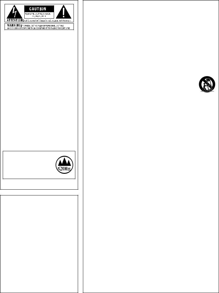
Rear Panel
|
|
|
|
|
|
|
|
|
|
|
|
|
|
|
|
|
|
|
1 |
2 |
3 |
4 |
5 |
6 |
|
7 |
|
|
|
|
|
||||||||||||||
|
|
|
|
|
|
|
|
|
|
|
|
|
|
|
|
|
|
|
|
|
|
|
|
|
|
|
|
|
|
|
|
|
|
|
|
|
|
|
|
|
|
|
|
|
|
|
|
|
|
|
|
|
|
|
|
|
|
|
|
|
|
|
|
|
|
|
|
|
|
|
|
|
|
|
|
|
|
|
|
|
|
|
|
|
|
|
|
|
|
|
|
|
|
|
|
|
|
|
|
|
|
|
|
|
|
|
|
|
|
|
|
|
|
|
|
|
|
|
|
|
|
|
|
|
|
|
|
|
|
|
|
|
|
|
|
|
|
|
|
|
|
|
|
|
|
|
|
|
|
|
|
|
|
|
|
|
|
|
|
|
|
|
|
|
|
|
|
|
|
|
|
|
|
|
|
|
|
|
|
|
|
|
|
|
|
|
|
|
|
|
|
|
|
|
|
|
|
|
|
|
|
|
|
|
|
|
|
|
|
|
|
|
|
|
|
|
|
|
|
|
|
|
|
|
|
|
|
|
|
|
|
|
|
|
|
|
|
|
|
|
|
|
|
|
|
|
|
|
|
|
|
|
|
|
|
|
|
|
|
|
|
|
|
|
|
|
|
|
|
|
|
|
|
|
|
|
|
|
|
|
|
|
|
|
|
|
|
|
|
|
|
|
|
|
|
|
|
|
|
|
|
|
|
|
|
|
|
|
|
|
|
|
|
|
|
|
|
|
|
|
|
|
|
|
|
|
|
|
|
|
|
|
|
|
|
|
|
|
|
|
|
|
|
|
|
|
|
|
|
|
|
|
|
|
|
|
|
|
|
|
|
|
|
|
|
|
|
|
|
|
|
|
|
|
|
|
|
|
|
|
|
|
|
|
|
|
|
|
|
|
|
|
|
|
|
|
|
|
|
|
|
|
|
|
|
|
|
|
|
|
|
|
|
1.INPUT
Connect your guitar to this high impedance 1/4” instrument input.
2.AUX IN
Using a stereo 1/8” cable, connect the headphone output of a portable music player to this 1/8” TRS connector to play along with all your favorite music. See Aux Input on page 32 for information on using this feature.
3.LEFT OUT/RIGHT OUT
These 1/4” TRS outputs can be configured for mono or stereo operation. Use them for connecting to a single guitar amplifier, a stereo pair of guitar amplifiers, or directly into the inputs of a mixer or recording device.
HINT:When connecting these output connectors directly to a mixer or recording device, you will want to select the “MIXER” option in the System Settings menu to enable Speaker Cabinet Compensation (SCC). See Output To on page 44 for more information on the MIXER
option.
NOTE: Mono/stereo operation is configured in the System Settings menu. See Output Mode on page 45 for more information on this configuration option.
4.HEADPHONE OUT
Connect your headphones to this 1/8” mini TRS connector.This output is optimized for use with headphones having an impedance of 60 Ohms or less.
NOTE:When only headphones are connected (nothing connected to the 1/4” outputs), the outputs are optimized for full range speakers/headphones. See Output To on page 44 for further information.
6 RP360 / RP360 XP
5.CONTROL IN
In the RP360 model, this connector accepts an external expression or volume pedal for real-time control of effect parameters, or a DigiTech FS3X Footswitch for additional footswitch control. In the RP360XP model, this connector accepts an FS3X Footswitch for additional footswitch control. See Expression Pedal Control on page 34 and Using An Optional FS3X Footswitch on
page 37 for further details.
6.USB
This USB connector connects the RP360/RP360XP processor to a computer for preset management using the Nexus editor/librarian software and/or streaming 4 channels of audio (2 channels to the computer and 2 channels from the computer) for recording to your favorite Digital Audio Workstation.
7.POWER
Connect only the included PS0913DC power supply to this connector.
RP360 / RP360 XP |
7 |
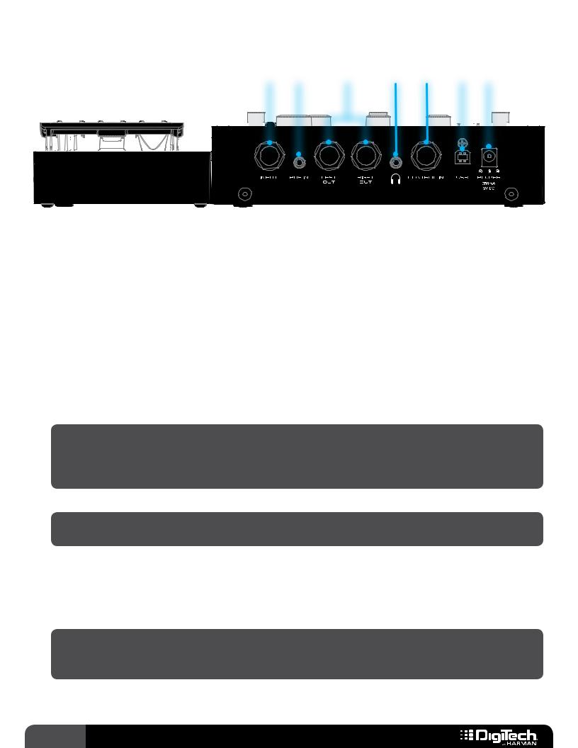
CONNECTION DIAGRAMS
Mono Amplifier
Amp 1
Guitar
Harman PS0913DC
Power Supply
Or
|
|
|
|
|
|
|
|
|
|
|
|
|
|
|
|
|
|
|
|
|
|
|
|
|
|
|
|
|
|
|
|
|
|
|
|
|
|
|
|
|
|
|
|
|
|
|
|
Optional |
|
Volume/Expression |
Footswitch |
||||
|
Pedal (RP360 Only) |
|
|
|
|||
|
|
|
|
||||
Follow these steps to use the RP with an amplifier:
1.Turn down the amplifier’s master volume control and power off the amp.
2.Make all the connections to the RP as shown in the diagram.
3.Turn the RP on by connecting the included power supply to the POWER input connector and connecting the other end to an available AC outlet.
4.Turn on your amplifier. Strum your guitar and gradually increase your amplifier’s master volume control until the desired level is achieved.
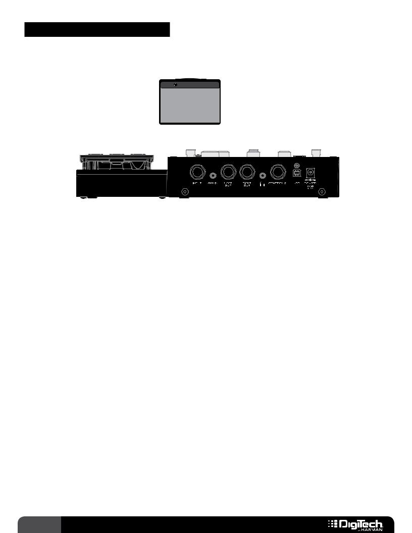
8 RP360 / RP360 XP
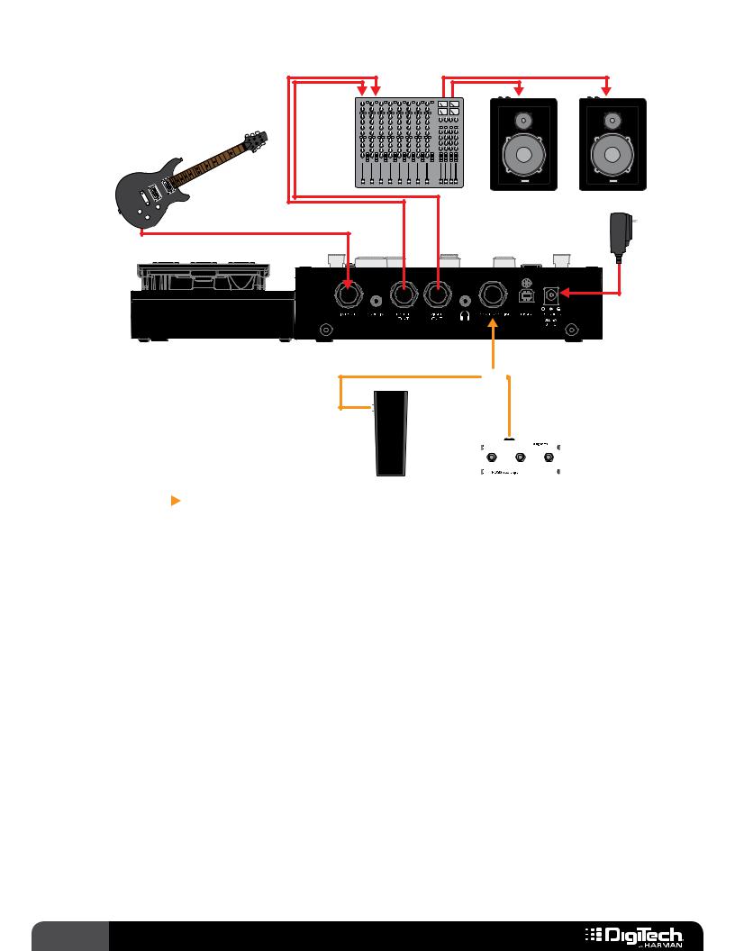
Stereo Amplifiers
|
|
Amp 1 |
|
|
|
|
|
Amp 2 |
|
|
|
|
|
|
|
|
|
|
|
|
|
|
|
|
|
|
|
|
|
|
|
|
Guitar
Harman PS0913DC
Power Supply
Or
|
|
|
|
|
|
|
|
|
|
|
|
|
|
|
|
|
|
|
|
|
|
|
|
|
|
|
|
|
|
|
|
|
|
|
|
|
|
|
|
|
|
|
|
|
|
|
|
Optional |
|
Volume/Expression |
Footswitch |
||||
|
Pedal (RP360 Only) |
|
|
|
|||
|
|
|
|
||||
Follow these steps to use the RP with a pair of amplifiers:
1.Turn down the amplifiers’ master volume controls and power off the amps.
2.Make all the connections to the RP as shown in the diagram.
3.Turn the RP on by connecting the included power supply to the POWER input connector and connecting the other end to an available AC outlet.
4.Turn on your amplifiers. Strum your guitar and gradually increase your amplifiers’ master volume controls until the desired level is achieved.
5.For stereo operation you will need to change the OUTPUT MODE parameter to STEREO. See Output Mode on page 45 for information on configuring the RP for stereo operation.
RP360 / RP360 XP |
9 |
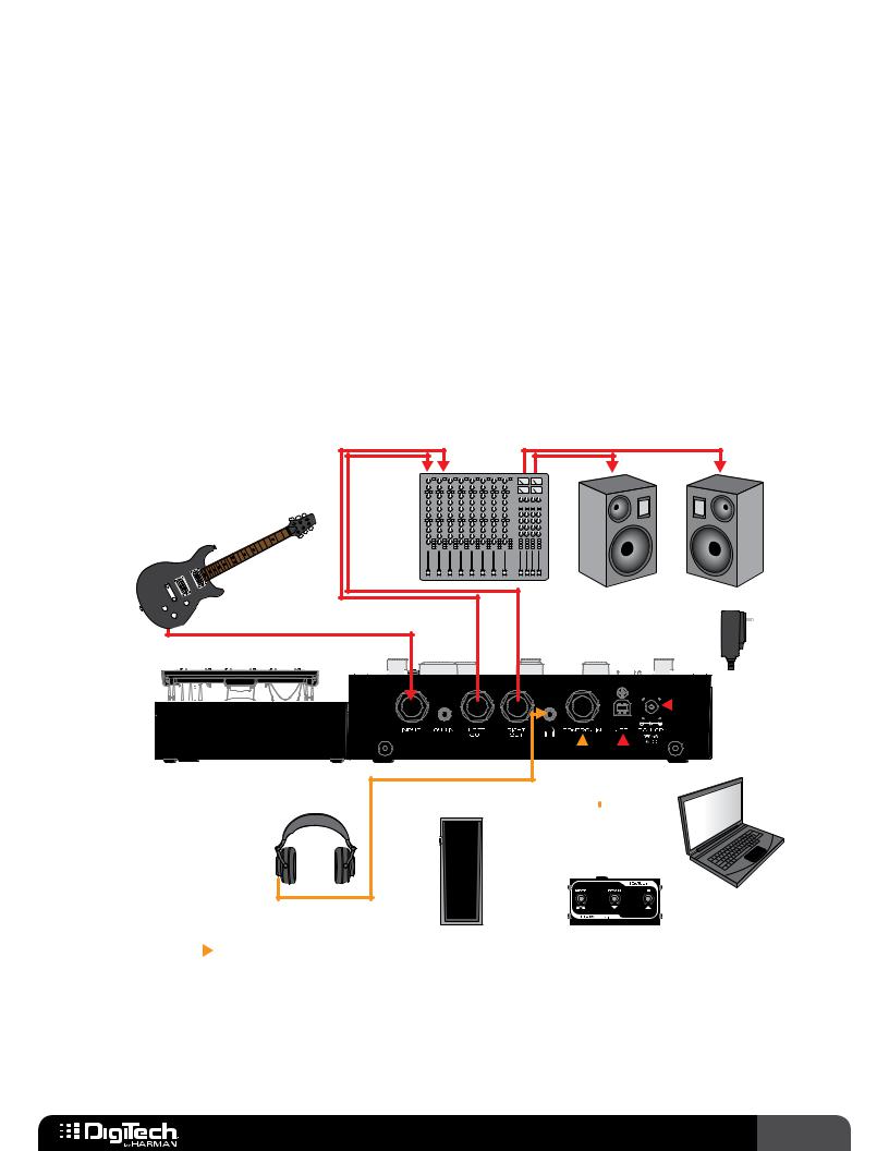
Direct To Mixer/PA
Mixer |
Guitar |
Powered PA Speakers
Harman PS0913DC
Power Supply
Or
|
|
|
|
|
|
|
|
|
|
|
|
|
|
|
|
|
|
|
|
|
|
|
|
|
|
|
|
|
|
|
|
|
|
|
|
|
|
|
|
|
|
|
|
|
|
|
|
Optional |
|
Volume/Expression |
Footswitch |
||||
|
Pedal (RP360 Only) |
|
|
|
|||
|
|
|
|
||||
Follow these steps to use the RP with a mixer:
1.Lower the master faders on the mixer.
2.Make all connections to the RP as shown in the diagram. Connect the RP to two mixer input channels. On these two mixer channels, turn down the input gains and faders and set one channel pan hard left and the other hard right.
3.Turn the RP on by connecting the included power supply to the POWER input connector and connecting the other end to an available AC outlet.
4.Strum your guitar and adjust the mixer levels until the desired level is achieved. Use proper gain staging to optimize the signal to noise ratio and prevent clipping of the mixer inputs. Consult your mixer documentation for information on proper mixer gain staging.
5.Change the OUTPUT TO parameter to MIXER in the System Settings menu.This will optimize the outputs for full range PA speakers. See Output To on page 44 for more information on editing this parameter.
6.For stereo operation you will need to change the OUTPUT MODE parameter to STEREO. See Output Mode on page 45 for information on configuring the RP for stereo operation.
10 RP360 / RP360 XP
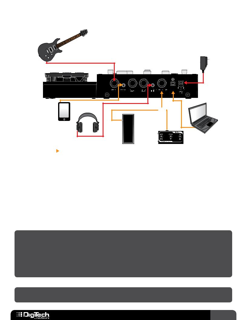
Computer Recording
The RP360 and RP360XP use the standard drivers which come with Mac OS X and Windows operating systems.Therefore, there are no additional drivers to install. Simply plug in the RP and connect to your computer.
The RPs will simultaneously stream 2 channels of audio up to the computer and 2 channels of audio down from the computer at a 44.1kHz sample rate with 16 or 24-bit resolution (bit resolution can usually be set in your DAW).Audio recorded via USB is taken from the audio feeding the RP’s LEFT and RIGHT outputs.
There are two parameters in the RP which are used for controlling your audio levels when recording, they are: the USB RECORD LVL parameter and the USB PLAY MIX parameter.These parameters allow you to control the level of the audio being recorded from the RP and the level of the playback audio from the DAW. See USB Record Level and USB Play Mix on page 47 for more information on these parameters.
Mixer
Guitar
Powered Monitors
Harman PS0913DC
Power Supply
|
|
|
|
|
|
|
|
|
|
|
|
|
|
|
|
|
|
|
|
|
|
|
|
|
|
|
|
|
|
|
|
|
|
|
|
|
|
|
|
|
|
|
|
|
|
|
|
|
|
|
|
|
|
|
|
|
|
|
|
|
|
|
|
|
|
|
|
|
|
|
|
|
|
|
|
|
|
|
|
|
|
|
|
|
|
|
|
|
|
|
|
|
|
|
|
|
|
|
|
|
|
|
|
|
|
|
|
|
|
|
|
|
|
|
|
|
|
|
|
|
|
|
|
|
|
|
|
|
|
|
|
|
|
|
|
|
|
|
|
|
|
|
|
|
|
|
|
|
|
|
|
|
|
|
|
|
|
|
|
|
|
|
|
|
|
|
|
|
|
|
|
|
|
|
|
|
|
|
|
|
|
|
|
|
|
|
|
|
Headphones |
|
|
|
|
|
|
|
|
|
|
|
|
|
|
|
|
|
|
|
|
|
|
|
|
|
|
|
||||||||
|
|
|
|
|
|
|
|
|
|
|
|
|
|
|
|
|
|
|
|
|
|
|
|
|
|
|
|
|
|
|
|
|
|
|
|
|||||||||
|
|
|
|
|
|
|
|
|
|
|
|
|
|
|
|
|
|
|
|
|
|
|
|
|
|
|
|
|
|
|
|
|
|
|
|
|||||||||
|
|
|
|
|
|
|
|
|
|
|
|
|
|
|
|
|
|
|
|
|
|
|
|
|
|
|
|
|
|
|
|
|
|
|||||||||||
|
|
|
|
|
|
|
|
|
|
|
|
|
|
Or |
|
|
|
|
|
|
|
|
|
|
|
|
|
|
|
|
|
|
|
|||||||||||
|
|
|
|
|
|
|
|
|
|
|
|
|
|
|
|
|
|
|
|
|
|
|
|
|
|
|
|
|
|
|
|
|
|
|
|
|
|
|
|
|
|
|
|
|
|
|
|
|
|
|
|
|
|
|
|
|
|
|
|
|
|
|
|
|
|
|
|
|
|
|
|
|
|
|
|
|
|
|
|
|
|
|
|
|
|
|
|
|
|
|
|
|
|
|
|
|
|
|
|
|
|
|
|
|
|
|
|
|
|
|
|
|
|
|
|
|
|
|
|
|
|
|
|
|
|
|
|
|
|
|
|
|
|
|
|
|
|
|
|
|
|
|
|
|
|
|
|
|
|
|
|
|
|
|
|
|
|
|
|
|
|
|
|
|
|
|
|
|
|
|
|
|
|
|
|
|
|
|
|
|
|
|
|
|
|
|
|
|
|
|
|
|
|
|
|
|
|
|
|
|
|
|
|
|
|
|
|
|
|
|
|
|
|
|
|
|
|
|
|
|
|
|
|
|
Computer
Optional |
|
Volume/Expression |
Footswitch |
|
Pedal (RP360 Only) |
|
|
|
|
Follow these steps to use the RP with a computer recording system:
1.Lower the master faders on the mixer.
2.Make all connections to the RP as shown in the diagram. Connect the RP to two mixer input
RP360 / RP360 XP 11

channels. On these two mixer channels, turn down the input gains and faders and set one channel pan hard left and the other hard right.
3.Turn the RP on by connecting the included power supply to the POWER input connector and connecting the other end to an available AC outlet.
4.Strum your guitar and adjust the mixer levels until the desired level is achieved. Use proper gain staging to optimize the signal to noise ratio and prevent clipping of the mixer inputs. Consult your mixer documentation for information on proper mixer gain staging.
5.Change the OUTPUT TO parameter to MIXER in the System Settings menu.This will optimize the outputs for full range studio monitor speakers. See Output To on page 44 for more information on editing this parameter.
6.For stereo operation you will need to change the OUTPUT MODE parameter to STEREO. See Output Mode on page 45 for information on configuring the RP for stereo operation.
7.In your DAW, select the RP as the input/output device. See your DAW’s documentation for further details.
HINT:The DigiTech Nexus editor/librarian software can also be used in this application to edit effects and manage presets. See Nexus Editor/Librarian Software on page 108 for further information.
12 RP360 / RP360 XP
Practicing With Headphones
Guitar
Harman PS0913DC
Power Supply 
Portable |
Headphones |
Or |
Music Player |
|
|
Computer
Optional |
|
Volume/Expression |
Footswitch |
|
Pedal (RP360 Only) |
|
|
|
|
Follow these steps to use the RP with headphones:
1.Make all the connections to the RP as shown in the diagram.
2.Turn the RP on by connecting the included power supply to the POWER input connector and connecting the other end to an available AC outlet.
3.Turn the EDIT 3 knob on the RP (the knob just below the SELECT knob) counter-clockwise to turn the RP’s Master Level control all the way down to 0.
4.Strum your guitar and turn the EDIT 3 knob on the RP clockwise until the desired level is achieved.
NOTE:When a pair of headphones is connected to the RP’s HEADPHONE connector and no connections are made to the 1/4” LEFT OUT or RIGHT OUT connectors, the RP will automatically set the OUTPUT TO parameter to “HEADPHONES IN USE” and the OUTPUT MODE parameter to “HEADPHONES IN USE”.This ensures the outputs are optimized for headphones and all stereo effects will be heard in stereo.These settings will return to the way they were configured as soon as you make a connection to the LEFT OUT or RIGHT OUT connectors.This makes it as simple as just plugging in your headphones to practice – no reconfiguration necessary!
NOTE:The HEADPHONE output is optimized for use with headphones having an impedance of 60 Ohms or less.
RP360 / RP360 XP 13
OPERATING INSTRUCTIONS
Basic Operation Overview
Performance State
Once the RP is powered up it is ready to use for performance.This is indicated by the current preset number and name being displayed in the LCD display. In this Performance state you can navigate presets and control the built-in Looper.
1 Plexi-Drive
LOOPER READY
There are three Footswitch Modes that can be used while in the Performance state: Preset Mode,
Stomp Mode, and Bank Mode. For more information on these Footswitch Modes, see Footswitch Modes on page 41. In the Performance state you can also control the Preset Level and Master Level parameters by turning the EDIT 1 and EDIT 3 knobs. See Preset Level & Master Level on page 25 for more information on these output level parameters.
Editing Presets
Press the SELECT knob to access the menus for editing preset parameters.You can use the SELECT knob and EDIT 1-3 knobs to navigate effects, make changes to effects and effect settings,
and add/delete/move effects in the signal chain. Once you are finished editing you can exit back to the Performance state by pressing any of the three FOOTSWITCHES or by pressing the BACK
button until the preset number and name are displayed in LCD display. See Working With Effects on page 19 for more information on editing effects.
System Settings
Pressing the SYSTEM button accesses the global System Settings menu where you can change footswitch and output modes, USB settings, and perform expression pedal calibration and factory restore operations. See System Setup on page 41 for more information on system settings.
Drums
Pressing the DRUMS button accesses the built-in Drum Machine. In this menu you have controls for turning the Drum Machine on and off and changing the drum pattern, tempo and level. See Drum Machine on page 30 for more information on using the Drum Machine.
14 RP360 / RP360 XP
Managing Presets
Navigating Presets
There are a total of 198 presets available in the RP360/RP360XP.These presets are broken up into two banks, User and Factory, each containing 99 presets. From the factory, the user and factory
presets will contain the same presets.Therefore, factory preset 45 will be the same as user preset 45 and so on. User presets appear in the LCD display as 1-99 and factory presets appear as
F1-F99. Preset banks will wrap around when navigating. In other words, navigating one preset above user preset 99 will select factory preset 1
(F1) in the factory preset bank. Navigating one
preset below user preset 1 will select factory preset 99 (F99) in the factory preset bank.To navigate and select presets you must be in the Performance state of operation.
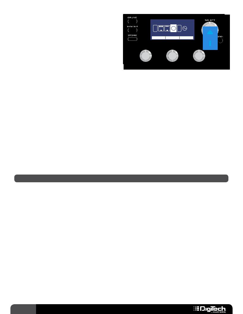
To navigate presets using the SELECT knob (Footswitch Mode set to “PRESET” or “STOMP”):
1.Footswitch Mode must be set to “PRESET” (this is the default Footswitch Mode) or “STOMP”. For more information on Footswitch Modes, see Footswitch Modes on page 41.
2.Turn the SELECT knob clockwise to navigate up through presets or counter-clockwise to navigate down through presets.
To navigate presets using the Footswitches (Footswitch Mode set to “PRESET”):
1.Footswitch Mode must be set to “PRESET” (this is the default Footswitch Mode). For more information on Footswitch Modes, see Footswitch Modes on page 41.
2.Press the UP FOOTSWITCH to navigate up through presets and press the DOWN FOOTSWITCH to navigate down through presets.
To navigate presets using the Footswitches (Footswitch Mode set to “STOMP”):
1.Footswitch Mode must be set to “STOMP”. For more information on Footswitch Modes, see
Footswitch Modes on page 41.
2.Press both FOOTSWITCHES 2 and 3 simultaneously.The LCD display will change, now showing the preset up/down navigation and looper icons, as well as the “LOOPER READY” prompt.
3.Press the UP FOOTSWITCH to navigate up through presets and the DOWN FOOTSWITCH to navigate down through presets. You’ll notice that the RP is now functioning just as it does when configured for Preset Mode operation.
RP360 / RP360 XP 15

4.When done navigating presets, press both FOOTSWITCHES 2 and 3 simultaneously again.The LCD display will change and you will now be back to Stomp Mode operation.
To navigate presets (Footswitch Mode set to “BANK”):
1.Footswitch Mode must be set to “BANK”. For more information on Footswitch Modes, see
Footswitch Modes on page 41.
2.If you want to select a preset from another bank, turn the SELECT knob clockwise to navigate up through banks or counter-clockwise to navigate down through banks – for easy hands-free preset bank navigation, an optional FS3X Footswitch should be used.There are 66 total banks
(33 user preset banks (1-33) and 33 factory preset banks (F1-F33)).After a bank is selected, the 3 footswitch LEDs will flash, prompting you to select a preset and activate the bank.
3.The LCD display will show 3 selectable presets in the selected bank. Press the corresponding FOOTSWITCH to load the desired preset.
NOTE: If a footswitch is not pressed within approximately 3 seconds, the RP will time out and revert back to the last active preset bank.
4.You can switch between Preset and Bank Mode operation to navigate presets when in Bank Mode.To do this, press both FOOTSWITCHES 2 and 3 simultaneously.The LCD display will change, now showing the preset up/down navigation and looper icons, as well as the “LOOPER READY” prompt.
5.Press the UP FOOTSWITCH to navigate up through presets and the DOWN FOOTSWITCH to navigate down through presets. You’ll notice that the RP is now functioning just as it does when configured for Preset Mode operation.
6.When done navigating presets, press both FOOTSWITCHES 2 and 3 simultaneously again.The LCD display will change and you will now be back to Bank Mode operation.
16 RP360 / RP360 XP
Storing/Copying/Naming Presets
The STORE button is used to store edits made to a preset’s parameters.The STORE button’s LED will light whenever a preset’s parameters have been modified from their stored value.Any
parameter edits must be stored to a preset before the processor is powered down or the preset is changed in order for edits to be retained. Preset edits can only be stored to a user preset
memory location since factory presets cannot be overwritten.The RP360 and RP360XP have 99 user preset memory locations. Factory presets can be edited and then stored to a user preset location. When storing a preset you will have the option to change the preset’s name.
To store/copy/rename a preset:
1.Press the STORE button to initiate the store procedure.
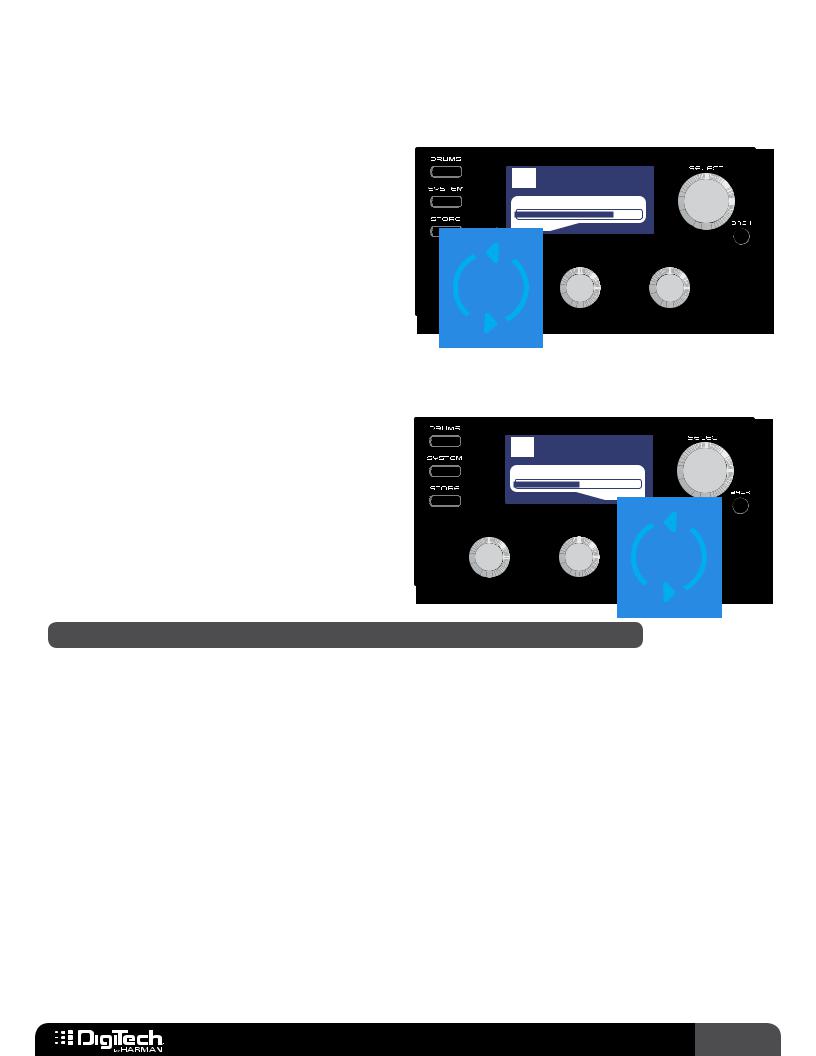
2.If you do not want to change the name of the preset, go to step 3.To modify or change the name, use the 3 EDIT knobs.Turning the EDIT 1 (LETTER) knob will edit the selected onscreen character.Turning the EDIT 2 (CURSOR) knob selects the character you want to edit. Turning the EDIT 3 (DEL/INS) knob clockwise will insert space to the left of the selected character; turning it counter-clockwise will delete characters to the left of the selected character.The preset name can contain up to 16 characters.
3.If you do not want to change the preset location go to step 4.To select a new preset location, turn the SELECT knob until the desired user preset memory location is displayed below the name.
4.Press the STORE button a second time, or press the SELECT button, to confirm the store procedure.The LCD display will briefly display “Storing...” then the preset will be stored.
NOTE: Pressing the BACK button at any time during the above store procedure will abort the procedure.
RP360 / RP360 XP 17

To quick store a preset (store a preset to its current memory location with its current name):
1.Press the STORE button twice.The LCD display will briefly display “Storing...” then the preset will be stored to its current user preset memory location with its current preset name.
WARNING! If you perform the above quick store procedure on a factory preset, the changes will be stored to the equivalent user preset memory location. For example, if you load factory preset
5 (F5), make edits, and then press the STORE button twice, you will overwrite user preset 5 (5). Therefore, use caution when performing this procedure on factory presets to ensure you do not accidentally overwrite one of your existing user presets.
To copy a preset to another preset location with its current name:
1.Select the preset you would like to copy.
2.Press the STORE button to initiate the store procedure.
3.Turn the SELECT knob until the desired user preset memory location is displayed below the preset name.
4.Press the STORE button a second time to confirm the store procedure.The LCD display will briefly display “Storing...” then the preset will be copied to the new user preset memory location.
18 RP360 / RP360 XP
Working With Effects
Effects can be modified, moved around, deleted, and added back into the effects chain.When the RP is configured for Stomp Mode, they can also be assigned to the three footswitches for effect on/off control. Up to 10 effects can reside in the effects chain at a time. This section of the manual describes how to work with the effects available in the RP360 and RP360XP processors.
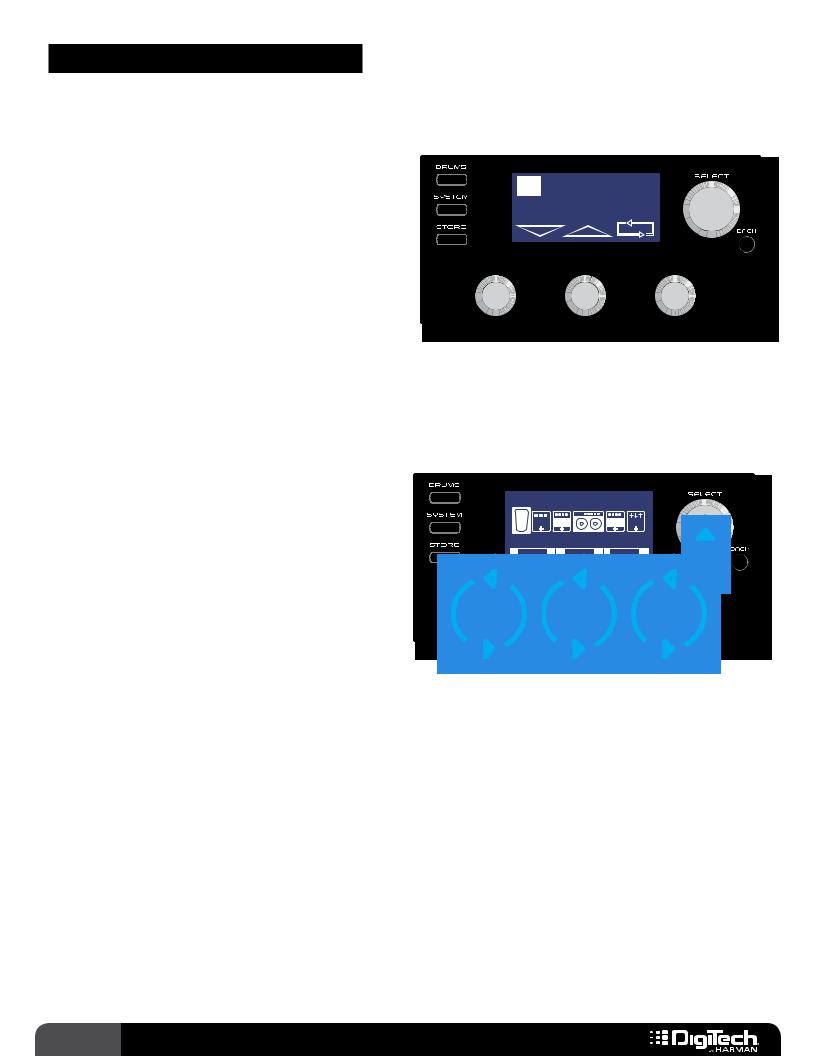
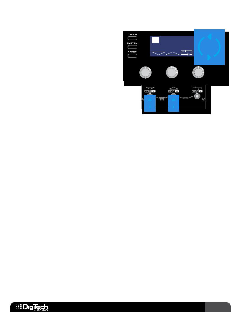
Editing Effect Parameters
When creating a new sound, you must start with an existing preset.The easiest way to create a new custom sound is to first load a preset which sounds close to the sound you are after.You can then edit the effects from there then store the preset to any of the 99 user preset memory locations.
To edit effect parameters:
CRY |
WAH |
|
1/2 |
W |
|
|
|
A |
CMP DST |
GAT EQ |
|
H |
|
|
|
BYPASS |
|
0 dB |
|
ON/BYP |
MODEL |
LEVEL |
|
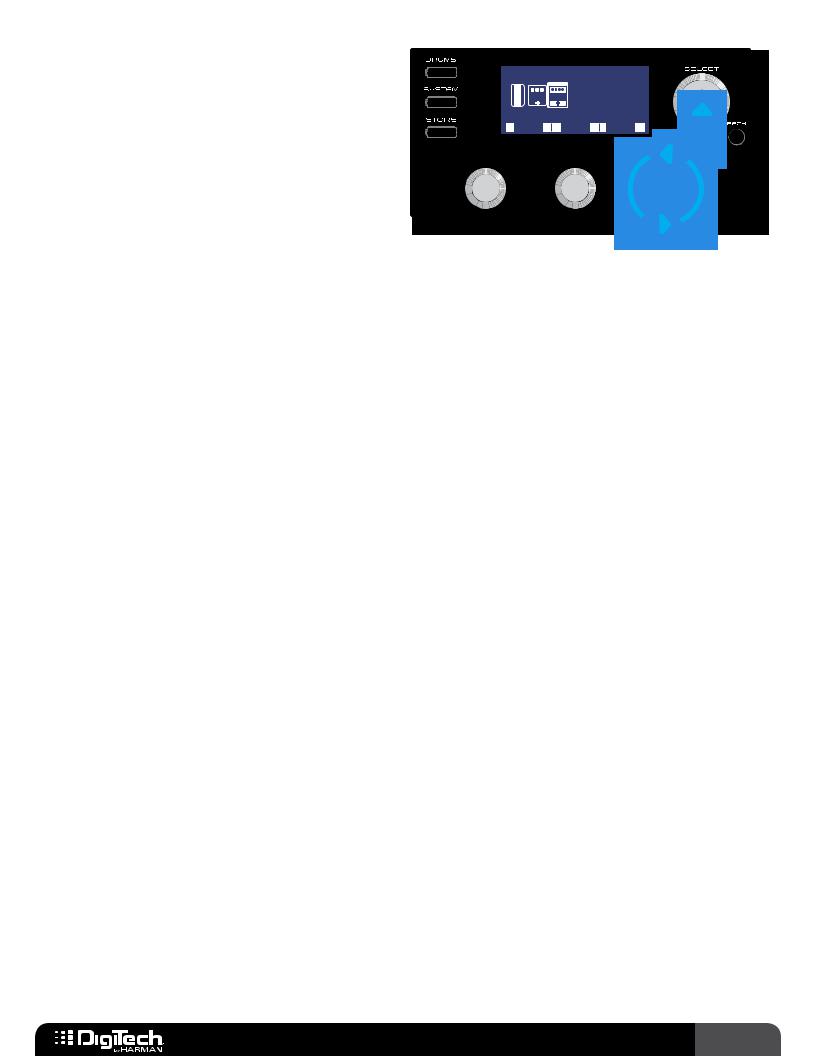
1.From the Performance state, press the SELECT knob to enter the Effect Edit menu.
2.Turn the SELECT knob to select the effect you would like to edit.
3.Turn the EDIT knobs to adjust the corresponding on-screen effect parameters. Some effects will have more than one page of parameters. If an effect has more than one page of parameters (designated by the 1/X page indicator in the upper right corner of the LCD display), press the SELECT knob to navigate the various pages.
4.When done, press the BACK button to return to the Performance state.
5.Store the changes to a user preset, see Storing/Copying/Naming Presets on page 17.
RP360 / RP360 XP 19
Changing Effects
Most of the effects in the RP360/RP360XP have multiple effects to choose from. For example, the Delay effect offers a Ping Pong Delay,Tape Delay, Analog Delay, etc..
To change an effect:
CRY |
WAH |
1/2 |
W |
|
|
A |
CMP DST |
GAT EQ |
H |
|
|
BYPASS |
0 dB |
|
ON/BYP |
LEVEL |
|
1.From the Performance state, press the SELECT knob to enter the Effect Edit menu.
2.Turn the SELECT knob to select the effect you would like to edit.
3.Turn the EDIT 2 knob to change the effect type.The selected effect will be shown at the top of the LCD display.
4.Repeat steps 2-3 to change any other effects.
5.When done, press the BACK button to return to the Performance state.
6.Store the changes to a user preset, see Storing/Copying/Naming Presets on page 17.
NOTE: Effects can also be changed from the Effect Options Edit menu.This menu is accessed by pressing and holding the SELECT knob when in the Effect Edit menu.You can then turn the EDIT 1 knob to change the effect model. From this menu, you can also move the effect to a different location in the effects chain or delete an effect from the effects chain.
20 RP360 / RP360 XP
Reordering Effects
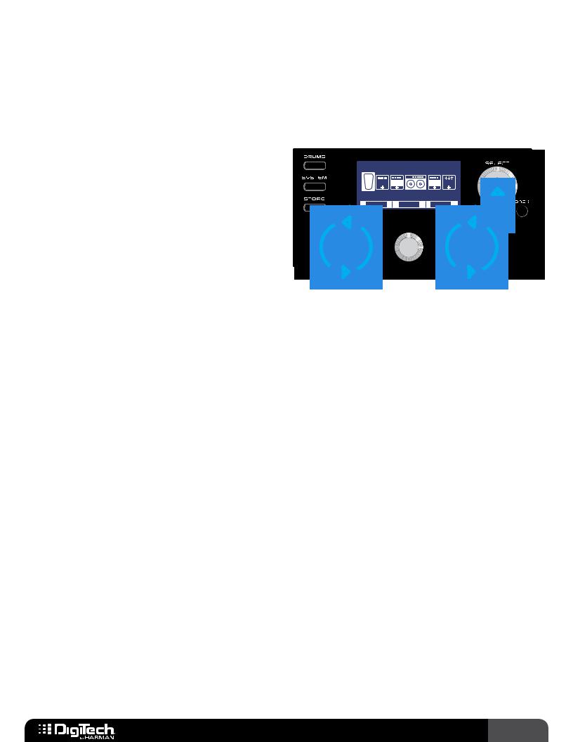
Each effect used in a preset may be moved into a different position in the effects chain.
To move an effect in the effects chain:
SCREAMER
W |
|
|
A |
DST |
GAT EQ |
H |
|
|
MODEL MOVE DELETE
1.From the Performance state, press the SELECT knob to enter the Effect Edit menu.
2.Turn the SELECT knob to select the effect you would like to move.
3.Press and hold the SELECT knob to access the Effect Options Edit menu.
4.Turn the EDIT 2 (MOVE) knob to move the selected effect left or right in the effect chain.
5.Press the SELECT knob to confirm the new placement.The display will return to the Effect Edit menu.
6.Repeat steps 2-5 to move any other effects.
7.When done, press the BACK button to return to the Performance state.
8.Store the changes to a user preset, see Storing/Copying/Naming Presets on page 17.
RP360 / RP360 XP 21
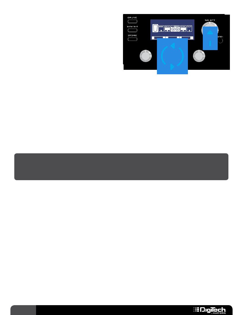
Adding Effects
Up to 10 effects can be used in each preset. If there is an available effect slot in a preset, the  icon will be displayed near the end of the Effect Edit menu.This
  icon is used to add an effect to the effects chain. If all 10 slots are already occupied with effects, the
  icon will not be visible.
|
|
|
Add |
Effect |
1/2 |
||||||
|
|
||||||||||
|
|
|
|
|
|
|
|
|
|
|
E |
|
|
|
|
V |
|
|
|
||||
|
|
|
|
O |
|
MOD DLY |
|
|
|
X |
|
|
|
|
|
L |
|
|
|
|
|
|
P |
|
|
|
|
|
|||||||
|
|
|
|
|
|
|
|
|
|
|
|
|
|
|
|
|
|
|
|
|
|
|
|
REVERB, CLICK TO CONFIRM
EFFECT
To add an effect to the effects chain:
1.From the Performance state, press the SELECT knob to enter the Effect Edit menu.
2.Turn the SELECT knob to navigate to the  (Add Effect) icon in the chain.“Add Effect” will appear at the top of the LCD display.
3.Turn the EDIT 1 (EFFECT) knob to select the available effect category (e.g., Compressor, Modulation, Reverb, etc.).
4.Press the SELECT knob to confirm the category selection.
5.You can change the type of the added effect by turning the EDIT 2 (MODEL) knob.
6.Once the desired effect has been selected, press the BACK button to return to the Performance state.
7.Store the changes to a user preset, see Storing/Copying/Naming Presets on page 17.
NOTE: One of each effect type (Compressor, Distortion, Modulation, etc.) can be used in a preset.
22 RP360 / RP360 XP
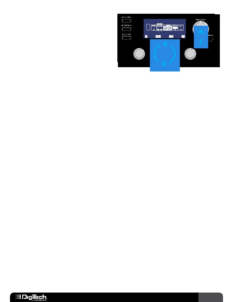
Deleting Effects
You can delete unused effects from the effects chain.This is not absolutely necessary since you can turn any unused effects off, but removing unused effects can clean up the Effect Edit menu, making it more streamlined and easier to edit effects.
To delete an effect from the effects chain:
TAPE DELAY
V
OL MOD DLY
MODEL MOVE DELETE
1.From the Performance state, press the SELECT knob to enter the Effect Edit menu.
2.Turn the SELECT knob to select the effect you would like to delete.
3.Press and hold the SELECT knob to access the Effect Options Edit menu.
4.Turn the DELETE knob to begin the delete procedure.“CLICK TO CONFIRM DELETE” will appear in the LCD display. If you change your mind, press the BACK button to abort deleting an effect.
5.Press the SELECT knob to confirm deletion.The effect will be deleted from the effects chain and the display will then return to the Effect Options Edit menu.
6.Press the BACK button twice to return to the Performance state.
7.Store the changes to a user preset, see Storing/Copying/Naming Presets on page 17.
RP360 / RP360 XP 23

Assigning Effects To Footswitches (Stomp Mode Only)
When the RP360/RP360XP is configured for Stomp Mode operation, effects can be assigned to any of the three footswitches.You can then toggle individual effects in a preset on and off during performance.
To assign an effect to one of the three footswitches:
|
|
|
|
|
Stompbox FSW |
1/1 |
|
|
|
|
|
|
|
|||
|
|
|
|
|
|
|
|
|
|
|
|
|||||
|
|
|
|
|
|
|
|
|
||||||||
|
|
|||||||||||||||
|
|
|
|
|
|
|
E |
|
|
|
|
|
|
|
|
|
|
|
|
|
|
|
|
|
|
|
|
|
|
|
|
|
|
|
|
|
|
|
MOD DLY |
REV PX |
|
|
|
|
|
|
|
|
|
|
|
|
|
|
|
|
|
|
|
|
|
|
|
|
|||
|
|
|
|
|
|
|
|
|
|
|
||||||
|
|
|
|
|
DIST ON |
WAH ON |
DLY ON |
|
|
|
|
|
|
|||
|
|
|
|
|
ASSIGN |
A |
ASSIGN B |
ASSIGN |
C |
|
|
|
|
|
|
|
|
|
|||||||||||||||
|
|
|
|
|
|
|
|
|
|
|
|
|
|
|
|
|
|
|
|
|
|
|
|
|
|
|
|
|
|
|
|
|
|
|
|
|
|
|
|
|
|
|
|
|
|
|
|
|
|
|
|
|
|
|
|
|
|
|
|
|
|
|
|
|
|
|
|
|
|
|
|
|
|
|
|
|
|
|
|
|
|
|
|
|
1.The RP must be configured for “Stomp Mode” operation, see Footswitch Modes on page 41 for information on configuring the RP for Stomp Mode operation.
2.From the Performance state, press the SELECT knob to enter the Effect Edit menu.
3.Turn the SELECT knob and select the  (Footswitch Assign) icon located at the end of the effects chain.
4.Turn the corresponding EDIT knobs to select the effects which will be assigned to the A, B, and C footswitches.
5.When done, press the BACK button to return to the Performance state.
6.Store the changes to a user preset, see Storing/Copying/Naming Presets on page 17.
24 RP360 / RP360 XP
Preset Level & Master Level
The RP360 and RP360XP have two different output level controls: Preset Level and Master Level.
Preset Level
The Preset Level parameter adjusts the output level for the currently loaded preset only. Therefore, changes to the Preset Level must be stored to the preset to be retained. Use the Preset Level parameter to either match the output
levels of all your presets or set the levels to create some dynamics in your songs (for example, a lead guitar part may require a slight boost in level to
push your guitar to the front of the mix and an intro may need a slightly lowered level to make the first verse sound bigger when it comes in).
Master Level
The Master Level parameter adjusts the global output level, which affects the volume of all presets equally. Use this parameter to increase or decrease the overall level of all presets.
1 Plexi-Drive
MASTER LEVEL: 43
NOTE: All outputs are affected by the Master Level and Preset Level parameters.
To adjust the Preset Level or Master Level parameter:
1.You must be in the Performance state to adjust these parameters.You should see the preset number and name in the LCD display. If you do not, press the BACK button until you do.
2.Turn the EDIT 1 knob to adjust the Preset Level.Turn the EDIT 3 knob to adjust the Master Level. While adjusting each parameter, the LCD display will temporarily display the level values as they are adjusted.After approximately 2 seconds of inactivity, the level parameter window will automatically disappear.
3.If you made changes to the Preset Level, the STORE button will light, indicating you must store the changes to a user preset. See Storing/Copying/Naming Presets on page 17 for information on storing presets.
RP360 / RP360 XP 25

Preset (Effects) Bypass |
BYPASS |
|
The Preset Bypass feature bypasses all effects in the currently |
||
|
||
loaded preset and feeds only the dry (unprocessed) signal to |
|
|
the outputs.While a preset is bypassed, no other functions are |
|
|
available.The bypassed guitar signal will be passed up USB while |
|
|
bypass is active, but no audio will be heard from the computer |
|
|
via USB. Bypass is accessed in different ways depending on the |
|
|
selected Footswitch Mode. See Footswitch Modes on page 41 |
|
|
for more information on Footswitch Modes. |
|
To bypass a preset’s effects (Footswitch Mode set to “PRESET” or “STOMP”):
1.Press FOOTSWITCHES 1 and 2 simultaneously to enable Preset Bypass.“BYPASS” will appear in the LCD display.
2.When done, press any footswitch to exit Preset Bypass.
To bypass a preset’s effects (Footswitch Mode set to “BANK”):
1.Press the currently active preset’s FOOTSWITCH (indicated by the lit LED above the footswitch).“BYPASS” will appear in the LCD display.
2.When done, press any footswitch to exit Preset Bypass.
26 RP360 / RP360 XP
 Loading...