


HARDWIRE
 V-10
V-10
POWER BLOCK
PREMIUM ISOLATED POWER SUPPLY
OWNER’S MANUAL

SAFETY INSTRUCTIONS
Notice For Customers If Your Unit Is Equipped With A Power Cord.
WARNING: THIS APPLIANCE SHALL BE CONNECTED TO A MAINS SOCKET OUTLET WITH A PROTECTIVE EARTHING CONNECTION.
The cores in the mains lead are coloured in accordance with the following code:
GREEN and YELLOW - Earth |
BLUE - Neutral |
BROWN - Live |
As colours of the cores in the mains lead of this appliance may not correspond with the coloured markings identifying the terminals in your plug, proceed as follows:
•The core which is coloured green and yellow must be connected to the terminal in the plug marked with the letter E, or with the earth symbol, or coloured green, or green and yellow.
•The core which is coloured blue must be connected to the terminal marked N or coloured black.
•The core which is coloured brown must be connected to the terminal marked L or coloured red.
This equipment may require the use of a different line cord, attachment plug, or both, depending on the available power source at installation. If the attachment plug needs to be changed, refer servicing to qualified service personnel who should refer to the following table. The green/yellow wire shall be connected directly to the units chassis.
|
CONDUCTOR |
WIRE COLOR |
||
|
Normal |
Alt |
||
|
|
|
||
L |
|
LIVE |
BROWN |
BLACK |
N |
|
NEUTRAL |
BLUE |
WHITE |
E |
|
EARTH GND |
GREEN/YEL |
GREEN |
WARNING: If the ground is defeated, certain fault conditions in the unit or in the system to which it is connected can result in full line voltage between chassis and earth ground. Severe injury or death can then result if the chassis and earth ground are touched simultaneously.
The following is indicative of low altitude use; do not use this product above 2000m.
CAUTION: Ensure vents on the V-10 are not blocked.
CAUTION: For Use with Audio/Video Equipment.
WARNING:
•Apparatet må tilkoples jordet stikkontakt
•Apparaten skall anslutas till jordat uttag
•Laite on liitettävä suojakoskettimilla varustettuun pistorasiaan

WARNING FOR YOUR PROTECTION READ THE FOLLOWING:
KEEP THESE INSTRUCTIONS
HEED ALL WARNINGS
FOLLOW ALL INSTRUCTIONS
The apparatus shall not be exposed to dripping or splashing liquid and no object filled with liquid, such as vases, shall be placed on the apparatus
CLEAN ONLY WITH A DRY CLOTH.
FOR INDOOR USE ONLY.
DO NOT BLOCK ANY OF THE VENTILATION OPENINGS. INSTALL IN ACCORDANCE WITH THE MANUFACTURER’S INSTRUCTIONS.
DO NOT INSTALL NEAR ANY HEAT SOURCES SUCH AS RADIATORS, HEAT REGISTERS, STOVES, OR OTHER APPARATUS (INCLUDING AMPLIFIERS) THAT PRODUCE HEAT.
ONLY USE ATTACHMENTS/ACCESSORIES SPECIFIED BY THE MANUFACTURER.
UNPLUG THIS APPARATUS DURING LIGHTNING STORMS OR WHEN UNUSED FOR LONG PERIODS OF TIME.
Do not defeat the safety purpose of the polarized or grounding-type plug. A polarized plug has two blades with one wider than the other. A grounding type plug has two blades and a third grounding prong. The wide blade or third prong are provided for your safety. If the provided plug does not fit your outlet, consult an electrician for replacement of the obsolete outlet.
Protect the power cord from being walked on or pinched particularly at plugs, convenience receptacles, and the point where they exit from the apparatus.
Use only with the cart stand, tripod bracket, or table specified by the manufacture, or sold with the apparatus. When a cart is used, use caution when moving the cart/apparatus combination to avoid injury from tip-over.
Refer all servicing to to qualified service personnel. Servicing is required when the apparatus has been damaged in any way, such as power-supply cord or plug is damaged, liquid has been spilled or objects have fallen into the apparatus, the apparatus has been exposed to rain or moisture, does not operate normally, or has been dropped.
POWER ON/OFF SWITCH: For products provided with a power switch, the power switch DOES NOT break the connection from the mains.
MAINS DISCONNECT: The plug shall remain readily operable. For rack-mount or installation where plug is not accessible, an all-pole mains switch with a contact separation of at least 3 mm in each pole shall be incorporated into the electrical installation of the rack or building.
FOR UNITS EQUIPPED WITH EXTERNALLY ACCESSIBLE FUSE RECEPTACLE: Replace fuse with same type and rating only.
MULTIPLE-INPUT VOLTAGE: This equipment may require the use of a different line cord, attachment plug, or both, depending on the available power source at installation. Connect this equipment only to the power source indicated on the equipment rear panel. To reduce the risk of fire or electric shock, refer servicing to qualified service personnel or equivalent.
If connected to 240V supply, a suitable CSA/UL certified power cord shall be used for this supply.
The symbols shown above are internationally accepted symbols that warn of potential hazards with electrical products. The lightning flash with arrowpoint in an equilateral triangle means that there are dangerous voltages present within the unit. The exclamation point in an equilateral triangle indicates that it is necessary for the user to refer to the owner’s manual.
These symbols warn that there are no user serviceable parts inside the unit. Do not open the unit. Do not attempt to service the unit yourself. Refer all servicing to qualified personnel. Opening the chassis for any reason will void the manufacturer’s warranty. Do not get the unit wet. If liquid is spilled on the unit, shut it off immediately and take it to a dealer for service. Disconnect the unit during storms to prevent damage.
U.K. MAINS PLUG WARNING
A molded mains plug that has been cut off from the cord is unsafe. Discard the mains plug at a suitable disposal facility. NEVER UNDER ANY
CIRCUMSTANCES SHOULD YOU INSERT A DAMAGED OR CUT MAINS PLUG INTO A 13 AMP POWER SOCKET. Do not use the mains plug without the fuse cover in place. Replacement fuse covers can be obtained from your local retailer. Replacement fuses are 13 amps and MUST be ASTA approved to BS1362.
ELECTROMAGNETIC COMPATIBILITY
This device complies with part 15 of the FCC Rules and the Product Specifications noted on the Declaration of Conformity. Operation is subject to the following two conditions:
•this device may not cause harmful interference, and
•this device must accept any interference received, including interference that may cause undesired operation.
Operation of this unit within significant electromagnetic fields should be avoided.
• use only shielded interconnecting cables.
If you want to dispose this product, do not mix it with general household waste. There is a separate collection system for used electronic products in accordance with legislation that requires proper treatment, recovery and recycling.
Private households in the 25 member states of the EU, in Switzerland and Norway may return their used electronic products free of charge to designated collection facilities or to a retailer (if you purchase a similar new one).
For Countries not mentioned above, please contact your local authorities for a correct method of disposal.
By doing so you will ensure that your disposed product undergoes the necessary treatment, recovery and recycling and thus prevent potential negative effects on the environment and human health.

DECLARATION OF CONFORMITY
Manufacturer’s Name: |
DigiTech |
Manufacturer’s Address: |
8760 S. Sandy Parkway Sandy, |
|
Utah 84070, USA |
declares that the product: |
|
Product name: |
V10 Power Block |
Note: |
Product name may be suffixed by |
|
the letters-EU. |
Product option: |
None |
conforms to the following Product Specifications: |
|
Safety: |
IEC 60065 -01 + Amd 2 |
EMC: |
EN 55022:2006 |
|
EN 55024:1998 |
|
FCC Part 15 |
Supplementary Information:
With regard to Directive 2005/32/EC and EC Regulation 1275/2008 of 17 December 2008, this product is designed, produced, and classified as Professional Audio Equipment and thus is exempt from this Directive.
Rex C. Reed
Director, Engineering
Signal Processing
8760 S. Sandy Parkway
Sandy, Utah 84070, USA
Date:April 24, 2013
European Contact:Your local DigiTech Audio Sales and Service Office or
Harman Professional Inc.
8760 South Sandy Parkway
Sandy, Utah
84070 USA
Ph: (801) 566-8800
Fax: (801) 568-7583
The product herewith complies with the requirements of the:
Low Voltage Directive 2006/95/EC
EMC Directive 2004/108/EC.
RoHS Directive 2011/65/EC
WEEE Directive 2002/96/EC
WARRANTY:
We at DigiTech® are very proud of our products and back-up each one we sell with the following warranty:
1.Please register online at www.digitech.com within ten days of purchase to validate this warranty. This warranty is valid only in the United States.
2.DigiTech warrants this product, when purchased new from an authorized U.S. DigiTech dealer and used solely within the U.S., to be free from defects in materials and workmanship under normal use and service. This warranty is valid to the original purchaser only and is non-transferable.
3.DigiTech liability under this warranty is limited to repairing or replacing defective materials that show evidence of defect, provided the product is returned to DigiTech WITH RETURN AUTHORIZATION, where all parts and labor will be covered up to a period of one year (this warranty is extended to a period of six years when the product has been properly registered through our website). A Return Authorization number may be obtained from DigiTech by telephone. The company shall not be liable for any consequential damage as a result of the product’s use in any circuit or assembly.
4.Proof-of-purchase is considered to be the responsibility of the consumer. A copy of the original purchase receipt must be provided for any warranty service.
5.DigiTech reserves the right to make changes in design, or make additions to, or improvements upon this product without incurring any obligation to install the same on products previously manufactured.
6.The consumer forfeits the benefits of this warranty if the product’s main assembly is opened and tampered with by anyone other than a certified DigiTech technician or, if the product is used with AC voltages outside of the range suggested by the manufacturer.
7.The foregoing is in lieu of all other warranties, expressed or implied, and DigiTech neither assumes nor authorizes any person to assume any obligation or liability in connection with the sale of this product. In no event shall DigiTech or its dealers be liable for special or consequential damages or from any delay in the performance of this warranty due to causes beyond their control.
NOTE: The information contained in this manual is subject to change at any time without notification. Some information contained in this manual may also be inaccurate due to undocumented changes in the product since this version of the manual was completed. The information contained in this version of the owner’s manual supersedes all previous versions.
Table of Contents
Introduction 2 Features 3 Included Items 3 Description 4 Pedalboard Mounting 8 About Negative & Positive Ground Effect Pedals 11 Getting Started 12 AC & DC Voltage 13 Power Plug Type & Size 14 Normal & Reversed Polarity 16 Voltage Requirements 18 Pedal Requirements Reference Table 22 The 8-Position DIP Switch 24 Variable Voltage Trim Controls 26 Power Cables 27
Specifications 30
1
Introduction
Thank you for purchasing the DigiTech® HardWire® V-10 Power Block. The V-10 Power Block is a regulated, high current power supply providing 10 fully isolated, short-circuit protected, low-noise outputs.
With a variety of voltages to choose from and an assortment of 17 included power cables, the V-10 can power a wide array of pedals on even the most demanding pedalboard designs.
The V-10 is right at home on virtually any pedalboard but was engineered to mount under the popular Pedaltrain® PT-JR/PT-1/PT-2 pedalboards or the Pedaltrain PT-3/PT-PRO pedalboards using their mounting bracket kit.
Providing ultra clean power to all your pedals, the V-10 is an essential addition for players who know about sound quality and demand the utmost in performance.
2
Features
•1200mA of Total Simultaneously Available Current
•Regulated Power Supply
•10 Fully Isolated, Short-Circuit Protected, Low-Noise Outputs
•Supplies a Variety of Voltages Including: 9V, 12V, & Variable 5-9VDC
•Mergable Outputs for Power-Hungry Pedals
•Prevents Ground Loops & Hum
•Shielded Toroidal Transformer for Ultra Quiet Operation
•Includes 17 Right-Angle Power Cables for Most Common Pedal Types
Included Items
•HardWire V-10 Power Block Isolated Power Supply
•Assortment of 17 Power Cables (see “Power Cables”)
•Mounting/Drill Template for Pedaltrain PT-JR/PT-1/PT-2
•Owner’s Manual
•Online Warranty Registration Information Card
3
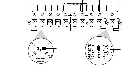
Description |
|
|
|
|
|
|
1 |
2 |
3 |
5 |
7 |
|
|
|
|
4 |
6 |
8 |
9 10 |
11 |
|
|
|
|
8 |
|
|
|
|
12 |
|
5 6 7 |
|
13 |
|
|
|
|
4 |
|
|
|
|
|
|
3 |
|
|
|
|
|
|
2 |
|
|
|
120V~60Hz |
|
ON |
1 |
|
|
|
|
|
|
|
|
|
40 WATTS
4
1.Power LED - This green LED illuminates when AC power is supplied to the V-10.
2.DC Power Output Jacks 1-4 - These four outputs provide fixed 9VDC power. The maximum allowable current draw on each of these outputs is 150mA (see “Specifications”).
3.DC Power Output Jacks 5-6 - These two outputs provide independently selectable 9VDC or 12VDC power. These outputs are mergable, allowing for connection of “power hungry” pedals which require more current. The maximum allowable current draw on each of these outputs is 200mA (unmerged). When merged, these outputs can provide a shared total of 400mA of available current (see “Specifications”). Note that even when these outputs are merged, they can still be independently set to 9VDC or 12VDC.
4.Merge Status LED 5-6 - This yellow LED indicates the merge status of outputs 5 and 6, illuminating when these outputs are merged.
5
5.DC Power Output Jacks 7-8 - These two outputs provide independently selectable 9VDC or 12VDC power. These outputs are mergable, allowing for connection of “power hungry” pedals which require more current. The maximum allowable current draw on each of these outputs is 150mA (unmerged). When merged, these outputs can provide a shared total of 300mA of available current (see “Specifications”). Note that even when these outputs are merged, they can still be independently set to 9VDC or 12 VDC.
6.Merge Status LED 7-8 - This yellow LED indicates the merge status of outputs 7 and 8, illuminating when these outputs are merged.
7.DC Power Output Jacks 9-10 - These two outputs are independently selectable and provide either fixed 9VDC power or variable 5-9VDC power. The maximum allowable current draw on each of these outputs is 150mA (see “Specifications”).
8.Trim Control (Output 9) - When power output 9 is configured for variable operation, use a flat-head screwdriver or the tip of your finger to turn this trim control to adjust the output’s voltage.
6
 Loading...