


Tube Preamp/Effects Processor & Controller
User’s Guide
Please visit Digitech Electronics on the World Wide Web at http://www.digitech.com
C A U T I O N |
RIS K O F ELECTRI C SHOCK |
D O NO T OPEN |
ATTENTION: RISQU E D E CHO C ELECTRIQU E - N E PA S OUVRIR |
WARNING: T O REDUC E TH E RIS K O F FIR E O R ELECTRIC SHOC K D O NO T EXPOS E THI S EQUIPMEN T T O RAI N O R MOISTURE
The symbols shown above are internationally accepted symbols that warn of potential hazards with electrical products.The lightning flash with arrowpoint in an equilateral triangle means that there are dangerous voltages present within the unit.The exclamation point in an equilateral triangle indicates that it is necessary for the user to refer to the owner’s manual.
These symbols warn that there are no user serviceable parts inside the unit. Do not open the unit. Do not attempt to service the unit yourself. Refer all servicing to qualified personnel. Opening the chassis for any reason will void the manufacturer’s warranty. Do not get the unit wet. If liquid is spilled on the unit, shut it off immediately and take it to a dealer for service. Disconnect the unit during storms to prevent damage.
WARNING
FOR YOUR PROTECTION, PLEASE READ THE FOLLOWING:
WATER AND MOISTURE: Appliance should not be used near water (e.g. near a bathtub, washbowl, kitchen sink, laundry tub, in a wet basement, or near a swimming pool, etc). Care should be taken so that objects do not fall and liquids are not spilled into the enclosure through openings.
POWER SOURCES: The appliance should be connected to a power supply only of the type described in the operating instructions or as marked on the appliance.
GROUNDING OR POLARIZATION: Precautions should be taken so that the grounding or polarization means of an appliance is not defeated.
POWER CORD PROTECTION: Power supply cords should be routed so that they are not likely to be walked on or pinched by items placed upon or against them, paying particular attention to cords at plugs, convenience receptacles, and the point where they exit from the appliance.
SERVICING: To reduce the risk of fire or electric shock, the user should not attempt to service the appliance beyond that described in the operating instructions. All other servicing should be referred to qualified service personnel.
FOR UNITS EQUIPPED WITH EXTERNALLY ACCESSIBLE FUSE RECEPTACLE: Replace fuse with same type and rating only.
U.K. MAINS PLUG WARNING
A moulded mains plug that has been cut off from the cord is unsafe. Discard the mains plug at a suitable disposal facility. NEVER UNDER ANY CIRCUMSTANCES
SHOULD YOU INSERT A DAMAGED OR CUT MAINS PLUG INTO A 13 AMP POWER SOCKET. Do not use the mains plug without the fuse cover in place. Replacement fuse covers can be obtained from your local retailer. Replacement fuses are 13 amps and MUST be ASTA approved to BS1362.
ELECTROMAGNETIC COMPATIBILITY
This unit conforms to the Product Specifications noted on the Declaration of Conformity. Operation is subject to the following two conditions:
•this device may not cause harmful interference, and
•this device must accept any interference received, including interference that may cause undesired operation. Operation of this unit within significant electromagnetic fields should be avoided.
•use only shielded interconnecting cables.
SAFETY INSTRUCTIONS
NOTICE FOR CUSTOMERS IF YOUR UNIT IS EQUIPPED WITH A POWER CORD.
WARNING: THIS APPLIANCE MUST BE EARTHED.
The cores in the mains lead are coloured in accordance with the following code:
GREEN and YELLOW - Earth |
BLUE - Neutral |
BROWN - Live |
As colours of the cores in the mains lead of this appliance may not correspond with the coloured markings identifying the terminals in your plug, proceed as follows:
•The core which is coloured green and yellow must be connected to the terminal in the plug marked with the letter E, or with the earth symbol, or coloured green, or green and yellow.
•The core which is coloured blue must be connected to the terminal marked N or coloured black.
•The core which is coloured brown must be connected to the terminal marked L or coloured red.
This equipment may require the use of a different line cord, attachment plug, or both, depending on the available power source at installation. If the attachment plug needs to be changed, refer servicing to qualified service personnel who should refer to the table below. The green/yellow wire shall be connected directly to the unit's chassis.
CONDUCTOR |
WIRE COLOR |
||
|
|
|
|
L |
Line |
Brown |
Black |
N |
Neutral |
Blue |
White |
|
Earth Grnd. |
Green/Yel. |
Green |
|
|
|
|
WARNING: If the ground is defeated, certain fault conditions in the unit or in the system to which it is connected can result in full line voltage between chassis and earth ground. Severe injury or death can then result if the chassis and earth ground are touched simultaneously.
LITHIUM BATTERY WARNING
CAUTION!
This product may contain a lithium battery.There is danger of explosion if the battery is incorrectly replaced. Replace only with an Eveready CR 2032 or equivalent. Make sure the battery is installed with the correct polarity. Discard used batteries according to manufacturer’s instructions.
ADVARSEL!
Lithiumbatteri - Eksplosjonsfare.Ved utskifting benyttes kun batteri som anbefalt av apparatfabrikanten. Brukt batteri returneres apparatleverandøren.
ADVARSEL!
Lithiumbatteri - Eksplosionsfare ved fejlagtig håndtering. Udskiftning må kun ske med batteri av samme fabrikat og type. Levér det brugte batteri tilbage til leverandøren.
VAROITUS!
Paristo voi räjähtää, jos se on virheellisesti asennettu.Vaihda paristo ainoastaan laitevalmistajan suosittelemaan tyyppin. Hävitä käytetty paristo valmistajan ohjeiden mukaisesti.
VARNING!
Explosionsfara vid felaktigt batteribyte.Använd samma batterityp eller en ekvivalent typ som rekommenderas av apparattillverkaren. Kassera använt batteri enligt fabrikantens instruktion.

RP-20 Valve
|
DECLARATION OF CONFORMITY |
Manufacturer’s Name: |
Digitech Electronics |
Manufacturer’s Address: |
8760 S. Sandy Parkway |
|
Sandy, Utah 84070, USA |
declares that the product: |
|
Product Name: |
RP-20 Valve |
Product Options: |
All |
conforms to the following Product Specifications:
Safety: |
EN 60065 (1993) |
|
IEC 65 (1985) with Amendments 1, 2 & 3 |
EMC: |
EN 55013 (1990) |
|
EN 55020 (1991) |
Supplementary Information:
The product herewith complies with the requirements of the Low Voltage Directive 73/23/EEC and EMC Directive 89/336/EEC as amended by Directive 93/68/EEC.
.
Digitech
President of Digitech
8760 S. Sandy Parkway
Sandy, Utah 84070, USA Tel: 801.566.8800
Fax: 801.566.7005
Effective August 30, 1997
European Contact: Your Local Digitech Sales and Service Office or
International Sales Office
3 Overlook Drive #4
Amherst, New Hampshire 03031, USA
Tel: 603.672.4244
Fax: 603.672.4246
|
|
|
User Guide |
I |
|
|
|
|
RP-20 Valve
Quick Start
For those of you who prefer to burn now and read later, we've included this Quick Start section to get you up and running.
Connect Cables:
Connect guitar into the Input jack (located on the rear of the RP-20). Now run from the Output of the RP-20 to the Input of the either the Guitar Amp, Power Amp or Mixing board.
Apply Power:
Note: When applying power to the RP-20 Valve, it is recommended that the <Input> and <Output> be turned down prior to powering up the unit.
Adjust Input and Output:
Use the <Input> level knob on the rear panel to adjust the Input level, so that the loudest guitar signal occasionally lights the clip LED indicator. Now adjust the <Output > level knob on the rear panel of the RP-20 Valve to the desired output level .
Select Preset:
Begin playing your guitar, and choose any preset using the <Data> wheel or pressing any one of the ten footswitches. User Presets 1-100 are duplicates of the Factory Presets. They are user-programmable. You can modify and store them as you want. Factory Presets 1-100 are not userprogrammable and cannot be overwritten.
Data
|
|
|
|
|
|
|
|
|
|
|
|
|
|
|
|
|
|
|
|
|
|
|
|
|
|
|
|
|
|
|
|
|
|
|
|
|
|
|
|
|
|
|
|
|
|
|
|
|
|
|
|
|
|
|
|
|
|
|
|
|
|
|
|
|
|
|
|
|
|
|
|
|
|
|
|
|
II |
|
|
|
|
|
|
|
|
|
User Guide |
|
|
|
|
|
|
|
|
|
|
|

RP-20 Valve
Table of Contents |
|
Safety Information |
|
Declaration of Conformity................................................................ |
i |
Quick Start........................................................................................ |
ii |
Table of Contents ............................................................................ |
iii. |
Section 1 - Introduction |
|
Congratulations ................................................................................ |
1 |
Included Items.................................................................................. |
1 |
Product Features .............................................................................. |
1 |
Warranty .......................................................................................... |
2 |
A Quick Tour of the RP-20 Valve ................................................ |
3 |
The Front Panel............................................................................ |
3 |
The Rear Panel.............................................................................. |
6 |
Prea mp Section .......................................................................... |
7 |
The Digital Effects Section .......................................................... |
8 |
Digital Effects .......................................................................... |
8 |
Real-Time Modifiers ................................................................ |
8 |
Module Types .............................................................................. |
9 |
Module Sizes ................................................................................ |
9 |
Section 2 - Setting Up |
|
Making Connections ...................................................................... |
10 |
RP-20 Valve into Extension Speaker Cabinets ............................ |
10 |
RP-20 Valve direct with the Programmable Speaker Cabinet |
|
Emulator ...................................................................................... |
11 |
Getting Around the Operating System........................................ |
12 |
Program Mode.............................................................................. |
12 |
FX Edit Mode................................................................................ |
12 |
Utility Mode.................................................................................. |
12 |
Assign Mode ................................................................................ |
12 |
Getting Sounds .............................................................................. |
13 |
Selecting A Program ...................................................................... |
15 |
Using the Tuner.............................................................................. |
15 |
Section 3 - Editing Program |
|
Naming/Storing Programs ............................................................ |
17 |
Editing a Program .......................................................................... |
19 |
Editing the Preamp section ........................................................ |
19 |
Editing the Analog Wah Module .................................................. |
20 |
Editing the Noise Gate module.................................................... |
21 |
Selecting FX Configurations ........................................................ |
22 |
Editing Digital FX ........................................................................ |
22 |
Changing Effect Modules ............................................................ |
23 |
Selecting Effect Defaults .............................................................. |
23 |
Adjusting FX Module Parameters ................................................ |
23 |
Custom Defaults .......................................................................... |
23 |
Comparing Changes .................................................................... |
24 |
|
|
|
User Guide |
III |
|
|
|
|

RP-20 Valve
Section 4 - Editing Modules |
|
Storing/Naming Defaults .................................................................. |
25 |
Editing a Module .............................................................................. |
26 |
Output Module Functions................................................................ |
27 |
Effect Module Size and Type List .................................................... |
28 |
Effect Default List ............................................................................ |
29 |
Effect Library ................................................................................ |
30 |
Preamp Section |
|
Analog Wah .................................................................................. |
30 |
Distortion Types .......................................................................... |
30 |
Noise Gate .................................................................................... |
31 |
Compressor .................................................................................. |
31 |
Digital Effects Section |
|
Reverbs ........................................................................................ |
32 |
Chorus & Flangers........................................................................ |
35 |
Phasers ........................................................................................ |
39 |
Rotary Speaker Simulator ............................................................ |
40 |
Tremolo & Auto Panner .............................................................. |
41 |
Pitch Shifters ................................................................................ |
42 |
Detuners ...................................................................................... |
44 |
Delays ........................................................................................ |
45 |
Equalizers .................................................................................... |
47 |
Multi Effect Modules .................................................................... |
48 |
Whammy Effects .......................................................................... |
49 |
Auto Wah ...................................................................................... |
51 |
Section 5 - Advanced Topics |
|
Assigning Modifiers .......................................................................... |
51 |
MIDI CC........................................................................................ |
51 |
LFO .............................................................................................. |
51 |
Dynamic........................................................................................ |
51 |
Internal Expression Pedal ............................................................ |
52 |
Linking a Parameter to a Modifier .............................................. |
53 |
Setting up an LFO and a Dynamic Modifier ................................ |
53 |
Morphing Pedal Assignments ...................................................... |
54 |
Volume Pedal Assignment............................................................ |
56 |
MIDI Functions |
|
MIDI Channels ............................................................................ |
57 |
MIDI Merging .............................................................................. |
57 |
MIDI Receive Map ........................................................................ |
57 |
MIDI Transmit Map ...................................................................... |
58 |
SysEx Device Channels ................................................................ |
58 |
SysEx Dumps................................................................................ |
58 |
Preset Dump ................................................................................ |
59 |
Bulk Dump .................................................................................. |
60 |
System Dump .............................................................................. |
61 |
Other Utility Functions |
|
Factory Reset ................................................................................ |
61 |
Global-Local Cabinet Emulator .................................................... |
62 |
Output Mode................................................................................ |
62 |
Assigning Functions |
|
Assigning Programs to footswitches ............................................ |
63 |
Assigning Parameter Control to footswitches or |
|
the Expression pedal.................................................................... |
64 |
Other Footswitch Functions |
|
Toggle MIDI CC .......................................................................... |
65 |
Expression CC Send .................................................................... |
65 |
CC Transmit Channel .................................................................. |
65 |
Other Pedalboard Tidbits |
|
Bank Up Tuner and Down/ Bypass Footswitches........................ |
66 |
Using the Tuner .......................................................................... |
66 |
Naming Banks .............................................................................. |
66 |
|
|
IV |
User Guide |
|
|

RP-20 Valve
Section 7 - Appendix |
|
Factory Program List .................................................................... |
68 |
Program Descriptions .................................................................. |
70 |
Effect Configuration Chart .......................................................... |
76 |
Harmony Interval Charts.............................................................. |
77 |
Specifications................................................................................ |
78 |
MIDI Implementation Chart ........................................................ |
79 |
SysEx Implementation Guide ...................................................... |
80 |
MIDI Basics .......................................................................... |
80 |
General Format .................................................................... |
81 |
Procedures ............................................................................ |
81 |
Request One Program01(h)................................................ |
82 |
Receive One Program42(h) ................................................ |
82 |
Request Bulk Dump - 49(h) ................................................ |
82 |
Receive Bulk Dump - 57(h) .................................................. |
82 |
Request Utility Settings - 11(h) ............................................ |
82 |
Receive Utility Settings - 12(h) ............................................ |
82 |
Request Parameter Value - 17(h).......................................... |
83 |
Receive Parameter Value - 18(h) .......................................... |
83 |
Request All Current Parameter Values - 23(h) .................... |
83 |
Receive All Current Parameter Values for current Prg ........ |
84 |
Request Module Configuration-25(h) .................................. |
84 |
Respond Module Configuration-26(h) ................................ |
84 |
Receive Key Scan Code - 54(h) ............................................ |
85 |
Receive Key Accepted - 56(h) .............................................. |
85 |
Select One Program - 1F(h).................................................. |
85 |
Reset Program - 20(h) .......................................................... |
86 |
Reset Device - 21(h).............................................................. |
86 |
Reset Factory Settings - 22(h) .............................................. |
86 |
Request User Defaults - 13(h) .............................................. |
86 |
Receive User Defaults - 14(h) .............................................. |
86 |
Key Scan Codes .................................................................... |
87 |
SysEx Program Dump Example ............................................ |
88 |
FX Modules and Parameter Codes ...................................... |
89 |
|
|
|
User Guide |
V |
|
|
|
|

RP-20 Valve
|
|
VI |
User Guide |
|
|

RP-20 Valve |
Section -1 Introduction |
Section-1 Introduction
Congratulations...
... you are now the proud owner of a Digitech RP-20 Valve Guitar Preamp/Processor. The RP-20 Valve is the first-ever Floor processor with a Tube (12AX7) Preamp section. This allows you to obtain almost any tone imaginable with a full menu of state of the art digital effects right at your feet.
This owner's manual is your key to understanding the powerful world of the RP-20 Valve. Read it carefully. After you've had time to familiarize yourself with the unit, try experimenting with unusual effect combinations. You are certain to achieve sounds never thought possible before. Good luck, and thank you for choosing Digitech.
Your RP-20 Valve was carefully assembled and packaged at the factory. Before you proceed any further, make sure the following items are included:
•(1) Owner’s Manual
•(1) Digitech RP-20 Valve Guitar Preamp/Processor
•(1)Power Supply
•(1) Digitech warranty card
Please save all packing materials. They were designed to protect the unit from damage during shipping. In the unlikely event that the unit requires service, use only the factory supplied carton to return the unit.
RP-20 Valve Features:
•Dual distortion path routing
•Built-in Expression Pedal
•Tube Preamp (12AX7)
•Full bandwidth effects (20-20kHz)
•24-bit signal path, 48-bit internal data path
•Up to 4 digital effects at once
•S-DISC II ® Processing
•Flexible, easy-to-use effect routing
•Effects can be repeated in a chain, (e.g. EQ + flange + EQ + pitch shift)
•Instant module access
•Exclusive Dynamic Parameter Control
•Programmable Speaker Cabinet Emulator
•Chromatic tuner
•Full MIDI Implementation
•All effects and parameters available for MIDI continuous control
•2 Expression Pedal insertion jacks to add external CC pedals for additional assigning options
•Upgradable System Software (via the MIDI In port)
|
|
|
User Guide |
1 |
|
|
|
|

Section -1 Introduction |
RP-20 Valve |
We at Digitech are very proud of our products and back-up each one we sell with the following warranty:
1.The warranty registration card must be mailed within ten days after purchase date to validate this warranty.
2.Digitech warrants this product, when used solely within the U.S., to be free from defects in materials and workmanship under normal use and service.
3.Digitech liability under this warranty is limited to repairing or replacing defective materials that show evidence of defect, provided the product is returned to Digitech WITH RETURN AUTHORIZATION, where all parts and labor will be covered up to a period of one year. A Return Authorization number may be obtained from Digitech by telephone. The company shall not be liable for any consequential damage as a result of the product's use in any circuit or assembly.
4.Proof-of-purchase is considered to be the burden of the consumer.
5.Digitech reserves the right to make changes in design, or make additions to, or improvements upon this product without incurring any obligation to install the same on products previously manufactured.
6.The consumer forfeits the benefits of this warranty if the product's main assembly is opened and tampered with by anyone other than a certified Digitech technician or, if the product is used with AC voltages outside of the range suggested by the
manufacturer.
7.The foregoing is in lieu of all other warranties, expressed or implied, and Digitech neither assumes nor authorizes any person to assume any obligation or liability in connection with the sale of this product. In no event shall Digitech or its dealers be liable for special or consequential damages or from any delay in the performance of this warranty due to causes beyond their control.
Digitech™, S-DISCII™, Whammy™, and Silencer II™ are registered trademarks of the Harman Music Group Incorporated.
NOTE: The information contained in this manual is subject to change at any time without notification. Some information contained in this manual may also be inaccurate due to undocumented changes in the product or operating system since this version of the manual was completed. The information contained in this version of the owner's manual supersedes all previous versions.
|
|
2 |
User Guide |
|
|
RP-20 Valve |
Section -1 Introduction |
A Quick Tour of the RP-20 Valve
The Front Panel
1 |
2 |
3 |
4 |
5a-f |
6 |
7 |
|
|
|
|
|
|
Data |
1)Pedalboard- The RP-20 Valves’s pedalboard consists of twelve switches and a real time expression pedal. the footswitches labeled 1-10 can be used to turn effects on or off, change presets or toggle continuous controller. The <Bypass/(hold) Tuner> footswitch (located on the bottom row can be used to bypass all of the effects within the RP-20 Valve or activate the tuner mode when held. The <Bank Up/(Hold) Bank down> footswitch is used to move up and down through any one of the 19 banks in the RP-20 Valve.
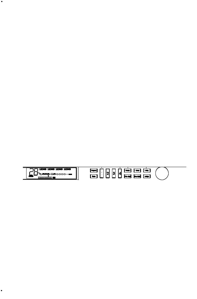
2)Display - This large custom display is where you receive most of the information you need to optimize performance of the RP-20 Valve. This display has several functions and they are as follows:
2-a 2-d 2-e
|
|
|
|
|
|
|
|
|
|
|
|
|
|
|
|
|
|
|
|
|
|
|
|
|
|
|
|
|
|
|
|
|
|
|
|
|
|
|
||
|
100 |
|
Edge of the Earth |
|
|
|
|
|
|
|
|
|
||||||||||||||||||||||||||||
|
|
|
|
|
|
|
|
%kHz |
|
|
|
|
|
|
%kHz |
|
|
|
|
%kHz |
|
|
|
|
|
%kHz |
||||||||||||||
|
|
1 |
2 |
3 |
|
4 |
||||||||||||||||||||||||||||||||||
|
|
|
|
50msdB |
|
|
60msdB |
|
70 msdB |
100 msdB |
||||||||||||||||||||||||||||||
|
|
|
|
|
|
|||||||||||||||||||||||||||||||||||
|
|
LINK |
CHANGED |
|
|
|
|
|
LINK |
CHANGED |
|
|
|
|
LINK |
CHANGED |
|
LINK |
CHANGED |
|
|
|
|
|||||||||||||||||
|
|
|
|
|
|
|
|
COMP WAH |
|
TUBE EQ |
# |
GATE |
|
|
|
|
|
|
|
|
||||||||||||||||||||
|
|
|
|
|
|
|
|
|
L/R OUTS |
|
|
|
||||||||||||||||||||||||||||
|
|
|
|
|
|
|
|
|
|
|
|
|
|
|
|
|
|
|
|
|
|
|
|
|
|
|
|
|
|
|
|
|
|
|
||||||
2-b |
|
|
USER |
b |
|
|
|
|
|
|
|
|
|
|
|
|
|
|
|
|
|
|
|
|
|
|
|
|
|
|
|
|
|
|
|
|
|
|
2-h |
|
|
BANK |
|
|
|
|
|
|
|
|
|
|
|
|
|
|
|
|
|
|
|
|
|
|
|
|
|
|
|
|
|
|
|
|
|
|
|
||||
|
|
|
|
|
|
|
|
|
|
|
|
|
|
|
|
|
|
|
|
|
|
|
|
|
|
|
|
|
|
|
|
|
|
|
|
|||||
|
|
|
|
|
|
|
|
|
|
|
|
|
|
|
|
|
|
|
|
|
|
|
|
|
|
|
|
|
|
|
|
|
|
|
|
|||||
|
PAGE10 OF11 |
|
|
|
|
|
|
|
|
|
|
|
|
|
|
|
|
|
|
|
|
|
CLIP |
|
|
|
|
|
|
|
|
|
|
|
|
|||||
|
|
|
|
|
|
|
|
|
|
|
|
|
|
|
|
|
|
|
|
|
|
|
|
|
|
|
|
|
|
|
|
|
|
|||||||
|
|
|
|
|
|
|
|
|
|
|
|
|
|
|
|
|
|
|
|
|
|
|
|
|
|
|
|
|
|
|
|
|
|
|
|
|
|
|||
|
2 |
-c |
|
|
|
|
|
|
|
|
|
2-f |
|
|
|
|
|
|
|
|
|
|
|
|
2-g |
|
|
|
|
|
|
|
|
|
||||||
2a) Program Number - The three large digits located in the upper left corner of the display indicate which Program is currently selected. This indicator will also display the currently selected note while the RP-20 Valve is in Tuner Mode.
2b) Factory / User indicators - Located directly below the Program number, the Factory and User program icons indicate whether the
|
|
|
User Guide |
3 |
|
|
|
|

Section 1 Introduction |
RP-20 Valve |
current program resides in the Factory or User Bank. To toggle between the Factory and User Programs simply press the <Program> button.
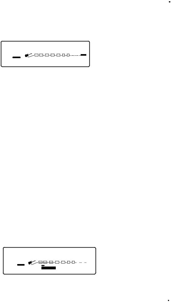
2c) Bank / Page Indicators - Located in the bottom left hand corner of the display, the Bank/Page indicators display:
•The RP-20 Valve Bank number in which the current program resides in Program Mode
•The page which is currently selected in various editing modes.
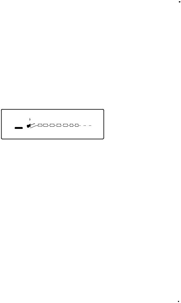
2d) Information Line - The row of 24 characters in the top line of the display indicates more detailed information about specific functions and items such as: Program names, Parameter names and Utility information.
2e) Parameter Data Sections - Immediately below the information line, are four parameter data sections. They correspond with buttons <1> through <4> on the front panel. Each section displays the current value of the indicated parameter.
A LINK icon in each group tells whether the indicated Parameter is linked for expression control. When a parameter has been modified, the CHANGED icon will appear under the parameter that has been modified and the <Store> button will light to indicate a change has been made to the program, but not stored.
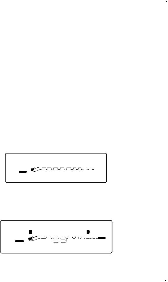
2f) Input Level / Clip Meters / Tune Indicator- An Input Level and Clip meter is located in the bottom center of the display. This meter shows the guitar signal level, and uses a peak detector action to display the highest levels at the input. The CLIP icon at the end of the meter, indicates if the the input signal is being clipped at the Analog input section (pre-digital). The DIGITAL CLIP icon indicates that there is clipping in the digital effects domain. This meter is also used to show note activity while the RP-20 Valve is in Tuner Mode
2g) Effect Routing Matrix - The Effect Routing Matrix shows the signal flow of the currently selected program through the amp and effect sections. This matrix includes boxes that represent each effect module along with lines that indicate how those effects are connected to inputs, outputs and each other. If an effect module is bypassed, a line appears through that module's box in the Matrix.
*When in FX Edit mode, the box that represents the currently selected effect module will flash.
2h) Speaker Cabinet Emulator Icon - When the SPEAKER icon appears in the display, this indicates that the Speaker Cabinet Simulator is engaged
3)Program and Store - The <Program> button (top) will put the RP-20 Valve in program mode and toggle between the Factory and User programs when pressed twice. The <Store> button is used to store any editing changes to a program.
4) Parameter Buttons- The parameter buttons <1> through <4> are used to select the parameter to be modified or the utility item that you wish to edit.
5a-f) Editing Buttons- These 6 buttons are used in the editing functions of the RP-20 Valve and their functions are as follows:
5a) Preamp - Pressing the <Preamp> button will enter the Preamp section of the RP-20 Valve. Successive presses will move through the individual modules of the preamp section including: Wah, Tube Distortion, Solid State Distortion, EQ and Noise gate.
5b) Effects - Pressing the <Effect> button will take you to the digital effects section. Successive presses of the effects button will move through the individual effect modules one at a time.
|
|
4 |
User Guide |
|
|

RP-20 Valve |
Section -1 Introduction |
5c) Utility - Pressing the <Utility> button will enter the utility mode where editing can be done.
5d) Previous Page - The <Previous Page> button moves to the previous page of the selected module that is being edited or to the previous utility page when the RP-20 Valve is in Utility mode.
5e) Next Page - The <Next Page> button moves to the next page of the selected module that is being edited or to the next utility page when the RP-20 Valve is in Utility mode.
5f) Assign - The <Assign> button is used for making any continuous controller assignments to footswitches. For more information about assigning functions, please see page 63.
6)Data Wheel - The <Data> Wheel is used for scrolling through the programs of the RP-20 Valve and various editing functions
7)Expression Pedal - The Expression pedal is used for continuous control over any parameter of the RP-20 Valve. For more about continuous control assignments of the RP-20 Valve, please see page 63.
|
|
|
User Guide |
5 |
|
|
|
|
Section -1 Introduction |
RP-20 Valve |
The Rear Panel
1 |
2 |
3 |
4 |
|
5 |
6 |
7 |
8 |
9 |
10 |
||||||||
|
|
|
|
|
|
|
|
|
|
|
|
|
|
|
|
|
|
|
|
|
|
|
|
|
|
|
|
|
|
|
|
|
|
|
|
|
|
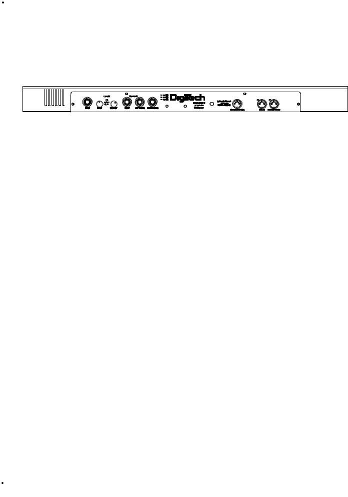
1)Input - This is the audio input jack for the RP-20 Valve.
2)Input Level - This is the input control knob for the RP-20 Valve. To achieve the optimal setting for the RP-20 Valve, turn the input knob up until the signal clip LED (3) occasionally lights when an input signal is fed into the RP-20 Valve.
3)Input Signal Clip LED - This is the Input signal clip LED of the RP-20 Valve. When this LED lights, the input signal is too strong and should be turned down until this LED only occasionally lights.
4)Output Level - This is the Output level control knob, and is used for setting the overall output level of the RP-20 Valve.
5)Right Output - This is the right output jack of the RP20 Valve.
6Left (Mono) Output - This is the left (Mono) audio output of the RP20 Valve. This output jack can be used as the Mono out or can be used with the right output to produce stereo outputs.
7)Headphone Out - This is the stereo headphone output. The headphone output level is controlled by the output level control knob
8)MIDI In - The MIDI IN port allows the RP-20 Valve to respond to incoming MIDI information.
9)MIDI Out/Thru - This port allows the RP-20 Valve to send out or pass MIDI data to other devices.
10)AC Line Input - This input is used for the input of the included power supply.
NoteUse only the included PS940 power supply.
|
|
6 |
User Guide |
|
|

RP-20 Valve |
Section -1 Introduction |
The Preamp Section
Dual Distortion Paths: A truly unique feature that the RP-20 Valves offers, is the ability to run dual distortion paths within the same effect configuration. What does this mean? This means that you can run your guitar’s signal through two distortion paths at the same time and morph between them. This is a great effect for producing clean and distorted tones at the same time.
Solid State Distortion Path: The Solid State distortion path in the RP-20 Valve gives you the ability to get great clean tones, classic rock fuzz distortions, and even high gain rock distortions.
Tube Distortion Path: The Solid State distortions are great to use alone, but the RP-20 Valve is the first to provide the user with Tube preamp tones in a floor mounted effects processor. This will give you the ability to re-create classic tube distortions which are ideal for playing country rock, blues and all out rock guitar.
Digitally Controlled Analog Wah: Conveniently located in the preamp section, lies a digitally controlled Analog Wah module. The Analog Wah will produce classic wahs, modern wahs, and even auto wahs. The Analog wah is assignable to the built-in expression pedal on the RP-20 Valve. For more information on using the Analog Wah with the expression pedal, please see pages 20.
Preamp Compressor: The RP-20 Valve provides you with a compressor in the preamp section to dial-in all of your preamp tones. The compressor can be used to tighten-up the clean rhythm tones or make a solo come to life.
Dual 10 band EQs: If having dual distortion paths within RP-20 Valve is not appealing enough, you also have 10-band EQ modules in each path. This will give complete tonal control over each distortion type that is being used.
Silencer II™ Noise gate To keep the RP-20 Valve ultra-quiet, we have included the world famous Silencer II™ noise reduction system under the hood. This make the RP-20 Valve an ideal piece for any studio recording.
|
|
|
User Guide |
7 |
|
|
|
|

Section -1 Introduction |
RP-20 Valve |
Digital Effects
Not only does the RP-20 Valve provide you great preamp tones, but it also has a world class digital multi-effect section that includes almost every studio-quality effect imaginable.
Effects include: |
|
• Reverbs (Natural & Spring) |
• Auto panners |
• Choruses |
• Analog/Digital Delays |
• Tremolos |
• Whammy Effects |
• Rotary Speaker Simulation |
• Chromatic Pitch Shifters |
• Phasers |
• Intelligent Pitch Shifter |
• Flangers |
• Detuners |
• Digital Compressor |
|
Real Time Parameter Modifiers: Modifiers are unique tools that can be used to dramatically alter your sound based on information from signal amplitude, the settings of a Low Frequency Oscillator (LFO) or MIDI Continuous Controller information.
Every Program in the RP-20 Valve has a set of modifiers. Up to 16 Modifier links can be assigned to control parameters. There are 5 types of Modifiers that can be linked to a parameter: Foot Switch, Expression Pedal, MIDI CCs, LFOs, and Dynamic (signal level dependent).
MIDI CCs: When you use MIDI CCs, your RP-20 Valve responds to CC numbers 0-127 and CHP (channel pressure or aftertouch).
For example, you can have a synth's modulation wheel (usually MIDI CC#1) control the Input level of a reverb and chorus in one Program, while the delay feedback may be controlled in another. For more information on MIDI CCs, please see pg. 51.
LFOs: When you use LFOs, parameter values can be controlled automatically between a defined minimum and maximum setting at a userdefinable rate. Your RP-20 Valve has 2 user definable LFOs in each program that can use unique speeds and waveforms, and can be assigned to any Parameter.
For example, you can create an auto panner without using an auto panner module. Simply link an effect's output pan parameter to the LFO modifier and the LFO will move that parameter back and forth. This modifier can be a very useful weapon in the ongoing battle of new sound creation. For more information on LFOs, please see pg. 51.
Dynamic Modifiers: When you use Dynamic Modifiers, the parameter values are controlled in relation to the dynamics of the input signal. The possibilities are nearly endless. For more information on Dynamic Modifiers, please see pg. 51.
For example, you could link the Dynamic Modifier of a Program to control a chorus level. It doesn't sound like much on paper, but imagine the expressiveness of this type of effect on a lead. As you play the guitar harder, the chorus becomes less apparent. Play softly and the chorus increases. ALL IN REAL TIME!
For more information on using modifiers see the “Assigning Modifiers” section on page 51.
|
|
8 |
User Guide |
|
|
RP-20 Valve |
Section - 1 Introduction |
Module Types
Each effect in the digital FX section is contained in separate effect blocks referred to as “Modules”. There are three basic types of FX Modules used by the Digital FX section of the RP-20 Valve
•Mono FX module
•Dual FX module
•Stereo FX module
The figure below illustrates how signals are routed through each type of FX Module. Although all three Modules are shown with stereo inputs, they can still be used with a mono source. The mono source would just be routed to both sides of the module’s inputs. Notice how the Dual FX Module maintains a stereo image, while the mono FX Module always sums the signal
L |
Mono FX Module |
L |
Dual FX Module |
L |
Stereo FX Module |
|
|
|
|||
|
Effect |
|
Effect |
|
Effect |
|
Processing |
|
Processing |
|
Processing |
R |
|
R |
|
R |
|
Module Sizes
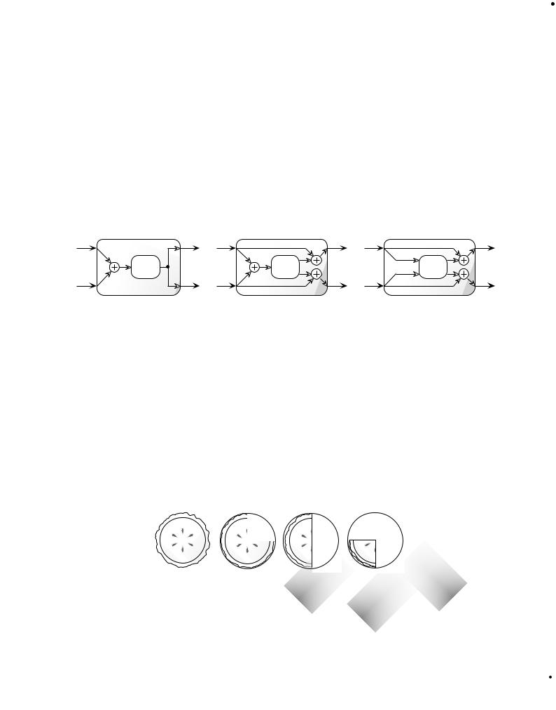
These modules vary in size ranging from 1/4 size to Full. In order to achieve the nearly endless combinations of effects and routings, we've supplied you with four different module sizes and they are as follows:
•Full (module type = FUL)
•3/4 (module type = 3-4)
•Half (module type = HLF)
•Quarter (module type = 4th)
Dividing the S-DISC II’s processing power allows your RP-20 Valve to produce up to 4 digital effects at one time. The figure below represents how the S-DISC II can be divided to accommodate a wide variety of effect routing.
FULL |
3/4 |
HALF |
QUARTER |
S-DISC II
A Full module type offers effects with more flexibility and power than the Half modules, and so on, but all four sizes of FX Modules feature high quality effects, so you don’t have to worry if you need to divide the S-DISC II pie four ways. For a complete list of these FX Types please see the Editing Modules section. For a complete list of effect configurations please see Appendix on page 76.
|
|
|
User Guide |
9 |
|
|
|
|

Section - 2 Setting Up |
RP-20 Valve |
Section-2 Setting Up
Making Connections
Your RP-20 Valve can be connected in several different ways to meet the requirements of specific applications. The following diagrams offer some different ways your RP-20 Valve can be connected.
|
Input |
Right Out |
Left (Mono) Out |
Right In |
Left (Mono) In |
Stereo 100 Power Amp
RP-20 Valve into a stereo power amp and two 2x12 Extension Speaker Cabinets
For those of you out there that feel that “bigger is better”, this set-up should work quite nicely for you. First plug into the input of the RP-20 Valve. RP-20 Valve run out of both of the outputs into the stereo inputs of the power amp. Using a set-up such as this will let you produce that classic Stack Sound. This is also a great set-up to produce lush and thick stereo effects.
|
|
10 |
User Guide |
|
|

RP-20 Valve |
Section - 2 Setting Up |
|
Input |
Right Output |
Left (Mono) Output |
4 |
6 |
|
4 |
6 |
|
4 |
6 |
|
4 |
6 |
|
4 |
6 |
|
4 |
6 |
|
4 |
6 |
|
4 |
|
6 |
2 |
|
8 |
2 |
|
8 |
2 |
|
8 |
2 |
|
8 |
2 |
|
8 |
2 |
|
8 |
2 |
|
8 |
2 |
|
8 |
0 |
Aux 1 |
10 |
0 |
Aux 1 |
10 |
0 |
Aux 1 |
10 |
0 |
Aux 1 |
10 |
0 |
Aux 1 |
10 |
0 |
Aux 1 |
10 |
0 |
Aux 1 |
10 |
0 |
Aux 1 |
10 |
4 |
6 |
|
4 |
6 |
|
4 |
6 |
|
4 |
6 |
|
4 |
6 |
|
4 |
6 |
|
4 |
6 |
|
4 |
|
6 |
2 |
|
8 |
2 |
|
8 |
2 |
|
8 |
2 |
|
8 |
2 |
|
8 |
2 |
|
8 |
2 |
|
8 |
2 |
|
8 |
0 |
Aux 2 |
10 |
0 |
Aux 2 |
10 |
0 |
Aux 2 |
10 |
0 |
Aux 2 |
10 |
0 |
Aux 2 |
10 |
0 |
Aux 2 |
10 |
0 |
Aux 2 |
10 |
0 |
Aux 2 |
10 |
-1 0 +1 |
|
-1 0 +1 |
|
-1 0 +1 |
|
-1 0 +1 |
|
-1 0 +1 |
|
-1 0 +1 |
|
-1 0 +1 |
|
-1 0 +1 |
|||||||||
-2 |
|
+2 |
-2 |
|
+2 |
-2 |
|
+2 |
-2 |
|
+2 |
-2 |
|
+2 |
-2 |
|
+2 |
-2 |
|
+2 |
-2 |
|
+2 |
-3 |
|
+3 -3 |
|
+3 -3 |
|
+3 -3 |
|
+3 -3 |
|
+3 -3 |
|
+3 -3 |
|
+3 -3 |
|
+3 |
|||||||
-4 |
|
+4 |
-4 |
|
+4 |
-4 |
|
+4 |
-4 |
|
+4 |
-4 |
|
+4 |
-4 |
|
+4 |
-4 |
|
+4 |
-4 |
|
+4 |
-5 |
Pan |
+5 |
-5 |
Pan |
+5 |
-5 |
Pan |
+5 |
-5 |
Pan |
+5 |
-5 |
Pan |
+5 |
-5 |
Pan |
+5 |
-5 |
Pan |
+5 |
-5 |
Pan |
+5 |
Mute |
|
|
Mute |
|
|
Mute |
|
|
Mute |
|
|
Mute |
|
|
Mute |
|
|
Mute |
|
|
Mute |
|
|
L / R |
|
|
L / R |
|
|
L / R |
|
|
L / R |
|
|
L / R |
|
|
L / R |
|
|
L / R |
|
|
L / R |
|
|
+10 |
|
|
+10 |
|
|
+10 |
|
|
+10 |
|
|
+10 |
|
|
+10 |
|
|
+10 |
|
|
+10 |
|
|
+5 |
|
|
+5 |
|
|
+5 |
|
|
+5 |
|
|
+5 |
|
|
+5 |
|
|
+5 |
|
|
+5 |
|
|
0 |
|
|
0 |
|
|
0 |
|
|
0 |
|
|
0 |
|
|
0 |
|
|
0 |
|
|
0 |
|
|
-5 |
|
|
-5 |
|
|
-5 |
|
|
-5 |
|
|
-5 |
|
|
-5 |
|
|
-5 |
|
|
-5 |
|
|
-10 |
|
|
-10 |
|
|
-10 |
|
|
-10 |
|
|
-10 |
|
|
-10 |
|
|
-10 |
|
|
-10 |
|
|
-20 |
|
|
-20 |
|
|
-20 |
|
|
-20 |
|
|
-20 |
|
|
-20 |
|
|
-20 |
|
|
-20 |
|
|
-30 |
|
|
-30 |
|
|
-30 |
|
|
-30 |
|
|
-30 |
|
|
-30 |
|
|
-30 |
|
|
-30 |
|
|
-∞ |
|
|
-∞ |
|
|
-∞ |
|
|
-∞ |
|
|
-∞ |
|
|
-∞ |
|
|
-∞ |
|
|
-∞ |
|
|
|
1 |
|
|
2 |
|
|
3 |
|
|
4 |
|
|
5 |
|
|
6 |
|
|
7 |
|
|
8 |
|
Running Direct with the Programmable Cabinet Emulator
The RP-20 Valve provides you with a speaker cabinet emulator for running direct to a mixing board.
When using the speaker cabinet emulator, it can be done by simply engaging cabinet Emulator in Page 2 of the Utilities menu. To get there, press the <Utilities> button. Now press the <Next Page> or <Previous Page>buttons and move to page 2. Once there, you can globally enable (global on) or disable (global off) the Emulator or enable local settings (local on) by pressing the <4> button and then turning the <Data> wheel. To set up local (Programs dependent) emulation on page 2 of the Output/Master mix module in edit mode press the <Effects> button until you reach the last page in the effect configuration chain where the master mix is located. Now press the <Next Page> button to move to page 2 of the parameters. use the <1> , <2> and <3> buttons to set the cabinet emulator parameters.
To Exit this mode, simply press the <Program> button.
At this point, you will want to run from either Left or Right outputs (or both for a stereo mix), into the selected inputs of the Mixer. You can set the Output mode to either Stereo (splitting the signal into a stereo soundfield) or Mono (summing the stereo signal) on page 1 of the Utilities menu by using the <2> button to select the mode.
As usual, it is a good idea to check all of the cables being used when making connections to ensure that good contact is being made. Notice that once the Speaker Cabinet Emulator is turned On, the SPEAKER icon will appear in the display.
|
|
|
User Guide |
11 |
|
|
|
|

Section - 2 Setting Up |
RP-20 Valve |
Getting Around In the Operating System
The menu structure of your RP-20 Valve has been specially designed to be easy to use. The display shows the information you need, but to make things even easier for you, illumination of the front panel buttons offers additional operating information.
The front panel buttons give you information in one of two ways:
1 - If the button is dim, its function is inactive. Pressing a dim button causes it to light brightly and its function becomes the active item in the display. If the dim button doesn’t light after you press it, the button is unavailable.
2 - If the button is bright, its function is active.
Program Mode
Program mode allows you to scroll through the Factory and User programs using the <Data> wheel. When your RP-20 Valve is turned on, it sets itself to Program mode. Program mode is active when the <Program> button is lit and a Program name is present on the information line (top line) of the display.
FX Edit Mode
This mode allows you to edit:
1.Digitally controlled Analog Wah
2.Compressor
3.Distortion Types
4.Noise Gate
5.Selecting Effect Configurations
6.FX Modules
7.Output Mode of your Programs
Use either the <Preamp> or <Effects> buttons to enter the FX Edit mode.
A helpful hint: If you look at the Effect Routing Matrix while you press the FX <Preamp> or <Effects> button, the currently selected module will flash.
Your RP-20 Valve uses “Pages” to navigate within an effect. A “Page” is a group of up to four effect parameters that appear on the screen at one time. Use the <Next Page > or <Previous Page> buttons to move through the pages in the menu. Note that as you scroll through the pages, the page indicator in the lower left corner of the display changes to show the currently displayed page number.
Utility Mode
From the initial power-up of the unit, access to all of the menu pages of the utility mode can be made by simply pressing the <Utility> button located on the front panel of the unit. From this point, the display will tell you that you are in the Utility mode and you can scroll through the options by turning the <Next Page > or <Previous Page> pages buttons.
Assign Mode
Once the RP-20 Valve is in assign mode, all modifier assignments can be made. This assign mode gives you the ability to assign dynamic modifiers, foot switches and the expression pedal to almost any parameter in the RP-20 Valve. Access to this function is located on the front panel <Assign> button or in the utilities pages within the RP-20 Valve. For more information on assignments, please see page 51.
|
|
12 |
User Guide |
|
|
RP-20 Valve |
Section - 2 Setting Up |
Getting Sounds
It never fails, there always seems to be a sound man at the back of the room, or an engineer in the control room that wants “more of this, or less of that” (bottom line: your ear is king). But, to accommodate these situations, you may need to make some minor adjusting here and there along the way. So here are some helpful guidelines for getting great sounds, while keeping everyone happy.
Input and Output Adjustments
The best setting for the input control is to use the <Input level> knob so you’re occasionally lighting the clip LED. As far as setting the <Output level> knob, let your ears be the judge. But, if you can’t hear the rest of the band, chances are that you need to back off on the output level of the RP-20 Valve.
Preamp Effects
Preamp Section Adjustments
When editing in the preamp section, you have the option of editing the following preamp effects:
1.Solid State Distortion
2.Tube Distortion
3.Analog Wah
4.Compressor
5.10-band EQ
6.Noise Gate
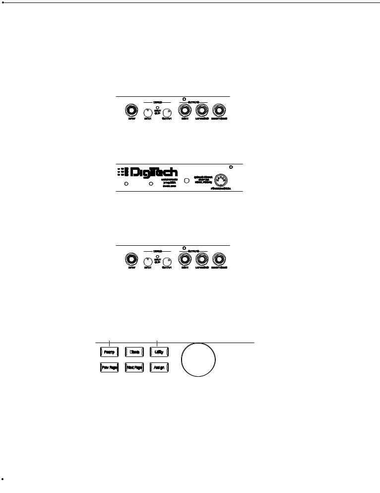
To dial in the preamp tone that is ideal for you, whether it be Distortion types, Analog Wah, 10-band EQ or noise gate adjustments, simply press the <Preamp> button, which will put you in preamp edit mode. From there continue to press the <Preamp> button until you reach the preamp module which you wish to edit. Notice that the module for editing will Flash in the display. Now that you are at the module that you wish to edit, you can begin to use the <Next Page> and <Previous Page> buttons to move you through the module. Once you arrive at a page you wish to edit, the display will show up to 4 parameters per page. To edit one of the parameters, simply press one of the four function buttons marked <1-4> to select the parameter. At this point you can scroll through that selected parameter by using the <Data> wheel. Once you have your sounds, always make sure to store and press the <Program> button to exit the edit mode.
The illustration below shows all of the editing tools needed for Preamp section editing.
Data
|
|
|
|
|
|
|
|
|
|
|
|
|
|
|
|
|
|
|
|
|
|
|
|
|
|
|
|
|
|
|
|
|
|
|
|
|
|
|
|
|
|
|
|
|
|
|
|
|
|
|
|
|
|
|
|
|
|
|
|
|
|
|
|
|
|
|
|
|
|
|
|
|
|
|
|
|
|
|
|
|
|
|
|
|
|
|
|
|
|
|
|
|
|
|
|
|
|
|
|
|
|
|
|
|
|
|
|
|
|
|
|
|
|
|
|
|
|
|
|
|
|
|
|
|
|
|
|
|
|
|
|
|
|
|
|
|
|
|
|
|
|
|
|
|
|
|
|
|
|
|
|
|
|
|
|
|
|
|
|
|
|
|
|
|
|
|
|
|
|
|
|
|
|
|
|
|
|
|
|
|
|
|
|
|
|
|
|
|
|
|
|
|
|
|
|
|
|
|
|
|
|
|
|
|
|
|
|
|
|
|
|
|
|
|
|
|
|
|
|
|
|
|
|
|
|
|
|
|
|
|
|
|
|
|
|
|
|
|
|
|
|
|
|
|
|
|
|
|
|
|
|
|
|
|
|
|
|
|
|
|
|
|
|
|
|
|
|
|
|
|
|
|
|
|
|
|
|
|
|
|
User Guide |
|
|
|
|
|
13 |
||||||||||||||||||||||||||||||||
|
|
|
|
|
|
|
|
|
|
|
|
|
|
|
|
|
|
|
|
|
|
|
|
|
|
|
|
|
|
|
|
|
|
|
|
|
|
|
|
Section - 2 Setting Up |
RP-20 Valve |
Digital Effects
Digital Effect Section Adjustments
When editing in the digital effect section, you have the option of editing the following:
1.Digital Effects
2.Wet/Dry Mix
3.Effect Configuration
4.Effect Module Size
When you are editing the digital effect section of the RP-20 Valve, whether it be effect type, Wet/Dry Mix, Effect configuration or module size, simply press the <Effects> button, which will put you in digital effect edit mode. From there continue to press the <Effect> button until you reach the digital effect module that you wish to edit. Notice that the module for editing will Flash in the display. Once you are at the module that you wish to edit, you can begin to use the <Next Page> and <Previous> page buttons to move you through the module. Once you arrive at a page you wish to edit, the display will show up to 4 parameters per page. To edit one of the parameters, simply press one of the four function buttons marked <1-4> to select the parameter. At this point you can scroll through that selected parameter by turning the <Program/Effect> wheel. Once you have your sounds always make sure to store and press the <Program> button to exit the edit mode.
The illustration below shows all of the editing tools needed for Digital Effect editing.
Data
|
|
|
|
|
|
|
|
|
|
|
|
|
|
|
|
|
|
|
|
|
|
|
|
|
|
|
|
|
|
|
|
|
|
|
|
|
|
|
|
|
|
|
|
|
|
|
|
|
|
|
|
|
|
|
|
|
|
|
|
|
|
|
|
|
|
|
|
|
|
|
|
|
|
|
|
|
|
|
|
|
|
|
|
|
|
|
|
|
|
|
|
|
|
|
|
|
|
|
|
|
|
|
|
|
|
|
|
|
|
|
|
|
|
|
|
|
|
|
|
|
|
|
|
|
|
|
|
|
|
|
|
|
|
|
|
|
|
|
|
|
|
|
|
|
|
|
|
|
|
|
|
|
|
|
|
|
|
|
|
|
|
|
|
|
|
|
|
|
|
|
|
|
|
|
|
|
|
|
|
|
|
|
|
|
|
|
|
|
|
|
|
|
|
|
|
|
|
|
|
|
|
|
|
|
|
|
|
|
|
|
|
|
|
|
|
|
|
|
|
|
|
|
|
|
|
|
|
|
|
|
|
|
|
|
|
|
|
|
|
|
|
|
|
|
|
|
|
|
|
|
|
|
|
|
|
|
|
|
|
|
|
|
|
|
|
|
|
|
|
|
|
|
14 |
|
|
|
|
|
|
|
|
|
|
|
|
|
|
|
|
|
|
|
|
|
|
|
|
|
|
|
|
|
|
|
|
|
|
|
|
User Guide |
|
|
|
|
|
|
|
|
|
|
|
|
|
|
|
|
|
|
|
|
|
|
|
|
|
|
|
|
|
|
|
|
|
|
|
|
|
|
|
|
RP-20 Valve |
Section - 2 Setting Up |
Selecting A Program
When you first turn on your RP-20 Valve, you are in Program Mode, and the display will appear something like:
2 |
Lush Clean |
3 |
|
||
1 |
2 |
4 |
|||
LINK CHANGED |
LINK CHANGED |
LINK CHANGED |
LINK CHANGED |
||
|
COMP WAH TUBE EQ |
GATE |
L/R OUTS |
||
USER |
b |
|
|
# CLIP |
|
PAGE OF11 |
|
|
|
||
To select a program, do the following:
1.Make sure program mode is selected (the <Program> button will be brightly lit). If the <Program> button is dim, press it once to return to program mode.
2.Use the <Program> button to select the program bank (factory or user). successive presses of the <Program> button toggle between the factory and user bank of programs.
3.Using the <Data> wheel, scroll to the Program you want to use, or press one of the footswitches.
Using the Tuner
The Tuner of the RP-20 Valve can be accessed pressing and holding the < Bank Down/Tuner> footswitch.
Instant Tuner Access
To instantly access the Tuner Mode of the RP-20 Valve, press and hold the <Bypass/Tuner> footswitch. This will take you directly to the tuner function.
1.As you play a note on the guitar, the large number display will tell you which note you are playing, while the meter will show you if you are flat or sharp. If the meter is moving right, the note you are playing is sharp. If the meter moves left, you are flat. The goal is to tune your guitar so that the meter stops moving, and the display will lock-in, indicating that you are in tune. Once you start playing the selected note, the display will read as follows:
127A |
A Tuner A=440 |
Output |
||||||||||||||||||
|
%kHz |
|
|
|
%kHz |
|
|
|
|
|
|
% |
|
|||||||
|
|
|
|
|
3 |
|
||||||||||||||
|
|
|
|
|
|
4 |
||||||||||||||
1 888msdB |
888msdB |
|
|
|
|
100 |
|
|||||||||||||
LINK CHANGED |
LINK CHANGED |
|
|
|
LINK CHANGED |
LINK CHANGED |
||||||||||||||
|
COMP WAH |
TUBE |
|
EQ |
# |
GATE |
|
|
|
|
|
|
|
|||||||
|
|
|
|
|
|
|
|
L/R OUTS |
|
|||||||||||
FACTORY USER |
b |
|
FX LOOP |
DIST |
|
|
|
EQ |
MIDI |
|
|
|
|
|
|
|
|
|||
|
|
|
|
|
|
|
|
|
|
|
||||||||||
BANK |
|
|
|
|
|
|
|
|
|
|
|
|
|
SOLO |
||||||
|
|
|
|
|
|
|
DIGITAL |
|
|
|
|
|
|
|||||||
PAGE19 OF18 |
|
|
|
|
|
|
|
CLIP |
|
|
|
|
|
|
L/R OUTS |
|||||
|
|
|
User Guide |
15 |
|
|
|
|

Section - 2 Setting Up |
RP-20 Valve |
Press the any button to exit the Tuner mode.
Reference and Output
The RP-20 Valve gives you the option of changing the Tuning reference from as low as F# or A=427 to A=453, by simply pressing the <3> button and then turning the <Data> wheel while the RP-20 Valve is in Tuner mode. Another feature available in the RP-20 Valve Tuner mode, is the ability to set the amount of signal that is passed to the output while tuning. This has a range from 0 (mute) to 100%. The output can be changed by pressing the <4> button and then turning the <Data>wheel to the desired level while the RP-20 Valve is in Tuner mode.
|
|
16 |
User Guide |
|
|
RP-20 Valve |
Section - 3 Editing Programs |
Section-3 Editing Programs
Naming and Storing Programs
Before we get into editing programs and creating your own sounds, let’s learn how to store changes so you won’t lose any modifications you’ll want to keep. The Store procedure allows you to rename, relocate and save any modifications you have made to programs so that they can be accessed easily later.
Naming the Program
1. Press the <Store> button once. The display shows the current program name (which may look something like this):
Name: Big Thick Clean
|
|
|
|
1 |
|
%kHz |
|
2 |
|
|
|
3 |
%kHz |
4 |
|
|
|
|
%kHz |
||
|
|
|
|
CAPmsdB |
nbr |
|
InSmsdB |
|
COpmsdB |
||||||||||||
|
|
|
|
|
|
|
|
|
|
||||||||||||
|
|
|
|
LINK CHANGED |
|
LINK CHANGED |
|
LINK CHANGED |
LINK CHANGED |
||||||||||||
|
2COMP |
WAH TUBE |
EQ GATE |
|
|
|
|
|
|
|
|||||||||||
|
|
|
|
|
|
|
L/R OUTS |
||||||||||||||
BANK |
USER |
b |
|
|
|
|
|
|
|
# |
DIGITAL |
|
|
|
|
|
|
|
|||
|
|
|
|
|
|
|
|
|
|
|
|
|
|||||||||
1 OF 1 |
|
|
|
|
|
|
|
|
|
|
|
|
|
|
|
|
|||||
PAGE |
|
|
|
|
|
|
|
|
|
|
|
|
|
|
|
|
|
|
|||
A cursor appears under the first character of the program name.
2.Using the <Data> wheel, change the character to the one you want in the selected position.
3.When the correct character is displayed in that position, press the <1> button and then turn then <Data> wheel to scroll the cursor to the next character you want to change.
4.Use the <1> button and the <Data> wheel to change the letter’s case. The <2> button and <Data> wheel are used to select numbers, The <3> button and <Data> wheel are used to insert spaces. The <4> button and <Data> wheel are used to copy and paste characters.
5.To copy a character, position the cursor under the character you want to copy (using the <Next Page > and <Previous Page> buttons), then press the <4> button and ten turn the <Data> wheel clockwise. To paste the copied character, position the cursor where you want to paste the character, then press the <4> knob and then turn the <Data> wheel counter-clockwise.
6.To abort the procedure, press any button other than <Store>.
|
|
|
User Guide |
17 |
|
|
|
|

Section - 3 Editing Programs |
RP-20 Valve |
Storing the Program
1. When you have the name how you want it, press the <Store> button again. The top line of the display appears something like this:
Store Prg to: Big Thick C
|
|
|
|
2 |
2 |
|
|
|
|
|
|
|
LINK CHANGED |
LINK CHANGED |
|
|
LINK CHANGED |
LINK CHANGED |
|
|
2COMP |
WAH |
TUBE |
EQ |
|
GATE |
L/R OUTS |
||
BANK |
USER |
b |
|
|
|
|
# |
|
|
1 OF 1 |
|
|
|
|
DIGITAL |
|
|||
PAGE |
|
|
|
|
|
|
|||
This screen allows you to select the location of the new Program. Note that when the Program is stored, it is stored in the User bank of programs because factory programs cannot be overwritten.
2.Press the <2> button and then turn the <Data> wheel to select the program number where you want to store the new program.
3.Press the <Store> button again. The top line of the display briefly reads:
Storing Program
|
|
|
|
2 |
3 |
|
|
|
|
|
|
|
LINK CHANGED |
LINK CHANGED |
|
|
LINK CHANGED |
LINK CHANGED |
|
|
2COMP |
WAH |
TUBE |
EQ |
|
GATE |
L/R OUTS |
||
BANK |
USER |
b |
|
|
|
|
# |
|
|
1 OF 1 |
|
|
|
|
DIGITAL |
|
|||
PAGE |
|
|
|
|
|
|
|||
after which you are taken to the program you have just stored.
The newly created program is now loaded, and can now be recalled at any time.
4. To abort the procedure, push the <Program> button to return you to program mode.
|
|
18 |
User Guide |
|
|
RP-20 Valve |
Section - 3 Editing Programs |
Editing a Program
The RP-20 Valve is capable of producing almost any guitar sound ever thought conceivable. Whether it be Preamp tone or an effect configuration that utilizes the most sophisticated digital effects available. Great sounds aren’t just a crazy concept, but a very achievable possibility, and in these next few pages, we will give you some pointers in editing programs, to help achieve your own unique tones.
Program Editing Sections
1.Preamp Section Editing
2.Digitally controlled Analog Wah Editing
3.Preamp Compressor
4.Noise Reduction Editing
5.Digital Effects Editing
Preamp Section Editing
From any program within the Preamp Section you can select and edit any preamp effect by performing the following procedures:
Editing Distortion Types
1. From program mode press the <Preamp> button once and the display will appear something like this:
|
|
|
|
Wah |
|
Pedal |
|
|
Toe Heavy |
|||||||||||
|
|
|
|
1 |
byp |
|
2 |
1 |
|
|
|
|
4 |
1 |
|
|
|
|
||
|
|
|
|
LINK CHANGED |
|
LINK CHANGED |
|
LINK CHANGED |
|
LINK CHANGED |
||||||||||
|
2COMP |
WAH TUBE EQ |
|
GATE |
|
|
|
|
|
|
|
|
||||||||
|
|
|
|
|
|
|
|
|
L/R OUTS |
|
||||||||||
BANK |
USER |
b |
|
|
|
|
|
# |
DIGITAL |
|
|
|
|
|
|
|
|
|
||
|
|
|
|
|
|
|
|
|
|
|
|
|
||||||||
1 OF 1 |
|
|
|
|
|
|
|
|
|
|
|
|
|
|
|
|
||||
PAGE |
|
|
|
|
|
|
|
|
|
|
|
|
|
|
|
|
|
|||
2. Now continue to press the <Preamp > button until only the selected distortion type (Tube or Solid State) flashes in the display. Once you are there, the display will appear something like this:
|
|
|
Tube Distort |
|
Dirty 1 |
|||
|
|
|
1 On |
2 |
|
|
3 |
4 F7 |
|
|
|
LINK CHANGED |
LINK CHANGED |
|
|
LINK CHANGED |
LINK CHANGED |
|
2COMP |
WAH TUBE |
EQ GATE |
L/R OUTS |
||||
BANK |
USER |
b |
DIST |
EQ |
# |
|
|
|
1 OF 2 |
|
|
|
DIGITAL |
|
|||
PAGE |
|
|
|
|
|
|||
|
|
|
User Guide |
19 |
|
|
|
|

Section - 2 Setting Up |
RP-20 Valve |
3.Pressing the <1> button and then turning the <Data> wheel will turn the distortion type on and the <4> button and <Data> wheel will select the default types of the distortion.
4.Once the distortion type has been selected, use the <Next Page> or <Previous Page> buttons to move to page 2 of the distortion type menu. Page 2 lets you select and adjust distortion type and gain amount by pressing the <2> button then turning the <Data> wheel you can select the distortion type. Pressing the <4> button and then turning the <Data> wheel you can adjust the gain.
|
|
|
Type: Dirty Tube |
Gain |
||||||||||||
|
|
|
1 |
|
|
|
|
|
3 |
|
|
|
|
|
|
|
|
|
|
2 |
3 |
|
|
4 |
45 |
||||||||
|
|
|
LINK CHANGED |
|
LINK CHANGED |
|
LINK CHANGED |
LINK CHANGED |
||||||||
|
2COMP |
WAH |
TUBE EQ |
|
GATE |
|
|
|
|
|
|
|
||||
|
|
|
|
|
|
|
|
L/R OUTS |
||||||||
BANK |
USER |
b |
|
|
|
|
|
# |
DIGITAL |
|
|
|
|
|
|
|
|
|
|
|
|
|
|
|
|
|
|
||||||
2 OF 2 |
|
|
|
|
|
|
|
|
|
|
|
|
||||
PAGE |
|
|
|
|
|
|
|
|
|
|
|
|
|
|||
5. Once the adjustments are made to the type and gain of the distortion type, make sure to store any changes
Analog Wah Editing
Analog Wah editing can be done by performing the following procedures:
1. From Program mode press the <Preamp > button until the Wah module is flashing. The display will appear something like this:
|
|
|
|
Wah |
|
Pedal |
|
|
Toe Heavy |
|||||||||||
|
|
|
|
|
byp |
|
|
1 |
|
|
|
|
|
|
1 |
|
|
|||
|
|
|
|
1 |
2 |
|
|
4 |
||||||||||||
|
|
|
|
LINK CHANGED |
|
LINK CHANGED |
|
LINK CHANGED |
|
LINK CHANGED |
||||||||||
|
2COMP |
WAH TUBE EQ |
|
GATE |
|
|
|
|
|
|
|
|
||||||||
|
|
|
|
|
|
|
|
|
L/R OUTS |
|
||||||||||
BANK |
USER |
b |
|
|
|
|
|
# |
DIGITAL |
|
|
|
|
|
|
|
|
|
||
|
|
|
|
|
|
|
|
|
|
|
|
|
||||||||
1 OF 1 |
|
|
|
|
|
|
|
|
|
|
|
|
|
|
|
|
||||
PAGE |
|
|
|
|
|
|
|
|
|
|
|
|
|
|
|
|
|
|||
2.Pressing the <1> knob and then turning the <Data> wheel will either turn the Wah On or Off. The <2> button is used to activate the Wah pedal range and the <4> button and <Data> wheel is used to select the Wah type.
3.The <2> (pedal parameter) can be assigned to the internal expression pedal. This is parameter can be selected by pressing the <2> button and then turning the <Data> and a Changed icon will appear directly beneath the parameter. At this point press the <Assign> button and the display will appear as follows:
|
|
20 |
User Guide |
|
|

RP-20 Valve |
Section - 3 Editing Programs |
Avail Link for: Pedal
1 OFF
|
|
LINK CHANGED |
LINK CHANGED |
|
|
LINK CHANGED |
LINK CHANGED |
|
2COMP |
WAH TUBE |
EQ |
|
GATE |
L/R OUTS |
|
BANK |
USER |
|
|
|
# |
|
|
1 OF 19 b |
|
|
|
DIGITAL |
|
||
PAGE |
|
|
|
|
|
||
4.Now press the Expression Pedal. If the Expression Pedal is already assigned to control another parameter, the display of the RP-20 Valve will ask you if you want to re-assign. If you wish to re-assign press the <1> knob and turn the <Data> wheel for yes or the <2> knob to abort the assign function.
Note: Any time an assignment to turn a parameter On/Off is made you must decide if you want the parameter On when you enter the selected program. If you want it on, make the assignment to the parameter when the parameter is set to On. Otherwise, have the parameter set to Off or Bypass and the parameter will not be active within the program until the footswitch is used to activate the parameter
5. To Exit the Analog Wah edit mode, simply press the <Program> button.
Noise Gate Editing
The procedure for editing the Noise Gate module within the preamp section is as follows:
1.From program mode, press the <Preamp> button until the Noise Gate module is selected and is flashing and the display appears something like this:
|
|
|
Noise Gate |
|
LoThresh |
||
|
|
|
1 On |
2 |
|
|
4 F 1 |
|
|
|
LINK CHANGED |
LINK CHANGED |
|
LINK CHANGED |
LINK CHANGED |
|
2COMP |
WAH TUBE EQ |
|
GATE |
L/R OUTS |
||
BANK |
USER |
b |
|
|
# |
|
|
1 OF 2 |
|
|
DIGITAL |
|
|||
PAGE |
|
|
|
|
|||
2.At this point, you can press the <1> button and then turn the <Data> wheel to turn the Noise gate On or Off and the <4> button and the <Data> wheel are used to select the Noise gate default.
4.Now use the <Next Page> button and move to page 2 of the Noise gate edit module. This page is used to set the Threshold, Attenuation, Attack and Release parameters. Higher Threshold settings will close the gate sooner. Lower Release settings allow the gate to open up faster. To adjust any of these parameters, use the numbered buttons <1-4> and then turn the <Data> wheel.
5.To exit Noise gate edit mode, press the <Program> button.
|
|
|
User Guide |
21 |
|
|
|
|

Section - 3 Editing Programs |
RP-20 Valve |
Selecting Effect Configuration Routes
Within every Program of the RP-20 Valve, you have the option of selecting any 1 of the 15 Effect Configuration routes available in the RP-20 Valve. This can be very helpful when you have a program that uses a preamp tone that you prefer, but the currently selected effect configuration is not ideal for the digital effects that you wish to use in the Program. You can easily change these Effect configurations by using the following procedure as a guide:
1. Accessing the effect configurations can be done by pressing the <Effects> button until the display appears like this:
Config: Series 4,4,4,4
|
|
|
1 |
1 |
|
|
|
|
|
|
|
|
LINK CHANGED |
LINK CHANGED |
|
|
LINK CHANGED |
LINK CHANGED |
|
|
2COMP |
WAH TUBE |
EQ |
|
GATE |
L/R OUTS |
|||
BANK |
USER |
b |
|
|
|
# |
|
|
|
1 OF 2 |
|
|
|
|
DIGITAL |
|
|||
PAGE |
|
|
|
|
|
|
|||
Note that the effect configuration is flashing
2.Now press the <1> button and then turn the <Data> wheel to select any one of the 15 different configurations available.
3.Once the configuration has been selected, press the <Store> button to save any changes.
4.To Exit the configuration menu, just press the <Program> button to return to program mode.
A Complete listing of the effect configurations of the RP-20 Valve can be found on page 76.
FX Edit Mode
1. From Program mode, press the <Effects> button. The display looks something like this:
|
|
|
Config: Series |
|
3,4 |
|||||
|
|
|
1 |
3 |
2 |
1 |
|
|
4 |
1 |
|
|
|
LINK CHANGED |
LINK CHANGED |
|
LINK CHANGED |
LINK CHANGED |
|||
|
2COMP |
WAH |
TUBE |
EQ GATE |
|
L/R OUTS |
||||
BANK |
USER |
b |
|
|
|
# |
|
|
|
|
1 OF 2 |
|
|
|
|
DIGITAL |
|
|
|||
PAGE |
|
|
|
|
|
|
|
|||
2. Successive presses of the <Effects> button will move you through the chain of effects modules.
When you enter FX Edit mode, the first page of every FX Module allows you to:
1)Bypass that effect module (by turning it on or off) by pressing the <1> button and then turning the <Data> wheel.
2)Select an Effect Module (Only in the Digital Effect section), by pressing the <2> button and then turning the <Data> wheel.
3)Store the Default by pressing the <3> button and then pressing the <Store> button (for more info on storing Defaults, see pg. 25.
4)Select a Default for the selected Effect Module by pressing the <4> button and then turning the <Data> wheel.
|
|
22 |
User Guide |
|
|
 Loading...