


Warranty
We at DigiTech are very proud of our products and back-up each one we sell with the following warranty:
1.The warranty registration card must be mailed within ten days after purchase date to validate this warranty.
2.DigiTech warrants this product, when used solely within the U.S., to be free from defects in materials and workmanship under normal use and service.
3.DigiTech liability under this warranty is limited to repairing or replacing defective materials that show evidence of defect, provided the product is returned to DigiTech WITH RETURN AUTHORIZATION, where all parts and labor will be covered up to a period of one year.A Return Authorization number may be obtained from DigiTech by telephone.The company shall not be liable for any consequential damage as a result of the product’s use in any circuit or assembly.
4.Proof-of-purchase is considered to be the burden of the consumer.
5.DigiTech reserves the right to make changes in design, or make additions to, or improvements upon this product without incurring any obligation to install the same on products previously manufactured.
6.The consumer forfeits the benefits of this warranty if the product’s main assembly is opened and tampered with by anyone other than a certified DigiTech technician or, if the product is used with AC voltages outside of the range suggested by the manufacturer.
7.The foregoing is in lieu of all other warranties, expressed or implied, and DigiTech neither assumes nor authorizes any person to assume any obligation or liability in connection with the sale of this product. In no event shall DigiTech or its dealers be liable for special or consequential damages or from any delay in the performance of this warranty due to causes beyond their control.
NOTE: The information contained in this manual is subject to change at any time without notification. Some information contained in this manual may also be
inaccurate due to undocumented changes in the product or operating system since this version of the manual was completed.The information contained in this version of the owner’s manual supersedes all previous versions.
GNX3000 Owner’s Manual

GNX3000 Owner’s Manual
Introduction........................................................... |
1 |
Quick Start..................................................................... |
3 |
Make Connections.................................................. |
3 |
Apply Power............................................................... |
3 |
Setups........................................................................... |
3 |
Single Amp.............................................................. |
3 |
Headphones........................................................... |
4 |
Mixer.......................................................................... |
4 |
Selecting Presets and Amp Models............... |
5 |
Presets....................................................................... |
5 |
Amp and Cabinet Models............................... |
5 |
Recording - Computer.......................................... |
6 |
Highlights of the GNX3000................................... |
8 |
The Programming Matrix..................................... |
8 |
The Control Panel................................................... |
8 |
The Expression Pedal............................................. |
9 |
Down/Up Footswitches...................................... |
9 |
Footswitches 1-5...................................................... |
10 |
GNX3000 Special Features..................................... |
11 |
Modes........................................................................... |
11 |
Amp Channels 1 and 2........................................... |
11 |
Amp Channel - Warped....................................... |
11 |
HyperModels............................................................. |
11 |
Getting Familiar with the GNX3000................. |
12 |
The Front Panel........................................................ |
12 |
The Rear Panel.......................................................... |
17 |
Audio Routing Setups.......................................... |
20 |
Setups Introduction................................................... |
20 |
Output Setups.............................................................. |
20 |
Speaker Compensation............................................ |
24 |
Mic and Line Setups.................................................. |
25 |
Optimizing the Mic and Line Input Levels..... |
26 |
Hooking It Up......................................................... |
27 |
Live Performance Setups......................................... |
27 |
Small Club Setup (Mono Amp Rig)................. |
27 |
Medium Stage Setup (Stereo Amp Rig)........ |
28 |
Large Stage Setup |
|
(Stereo Amp/Cabinet Rig).................................. |
29 |
TalkerTM Performance Setup............................... |
30 |
Computer Recording Setup................................... |
31 |
Applying Power............................................................ |
33 |
About the GNX3000............................................ |
34 |
Presets..... ......................................................................... |
34 |
Learn-A-Lick................................................................... |
34 |
Using Learn-A-Lick.................................................. |
34 |
Bypass............................................................................... |
35 |
Tuner.................................................................................. |
35 |
Footswitch Modes...................................................... |
36 |
Preset Mode.............................................................. |
36 |
Stompbox Mode...................................................... |
37 |
Record/Drum Mode............................................. |
37 |
Expression Pedal ......................................................... |
37 |
GNX3000 Matrix Functions ............................... |
38 |
The GNX3000 Matrix............................................ |
38 |
Viewing/Editing GeNetXTM and |
|
Amp Parameter Values.......................................... |
39 |
Viewing/Editing Effect Parameter Values... |
39 |
GeNetX Row.............................................................. |
40 |
CHAN ONE EQ and |
|
CHAN TWO EQ Rows.......................................... |
41 |
TONE Row.................................................................. |
43 |
Amp/Cabinet Modeling...................................... |
44 |
Amp Models.............................................................. |
44 |
Cabinet Types........................................................... |
46 |
Editing Amps and Cabinets................................ |
46 |
Selecting Amps and Cabinets........................ |
47 |
Adjusting Amp Parameters ............................. |
47 |
Cabinet Tuning...................................................... |
48 |
Storing Amp Parameter Edits......................... |
48 |
Creating HyperModelsTM .................................... |
48 |
Saving HyperModelsTM (Amp Save)................ |
48 |
Effects and Parameters....................................... |
50 |
Editing a Preset’s Effects...................................... |
50 |
Effect Definitions.................................................... |
51 |
Wah-Pickup............................................................ |
51 |
Compressor ........................................................... |
52 |
WhammyTM/IPS/Talk ...................................... |
53 |
Whammy............................................................. |
54 |
Intelligent Pitch Shifting (IPS) ................... |
55 |
Detune ................................................................. |
56 |
Pitch Shift .......................................................... |
56 |
TalkerTM................................................................. |
57 |
GNX3000 Owner’s Manual

Table of Contents
Stompbox Modeling.......................................... |
58 |
Noise Gate.............................................................. |
60 |
Chorus/Mod Effects......................................... |
61 |
Chorus................................................................... |
62 |
Flanger.................................................................. |
63 |
Phaser.................................................................... |
64 |
Triggered Flanger............................................. |
65 |
Triggered Phaser............................................... |
65 |
Unovibe................................................................ |
66 |
Tremolo................................................................ |
66 |
Panner................................................................... |
67 |
Vibrato.................................................................. |
67 |
Rotary Speaker................................................. |
68 |
AutoYaTM.............................................................. |
69 |
YaYaTM ................................................................... |
70 |
SynthTalkTM......................................................... |
71 |
Envelope Filter.................................................. |
71 |
Detune ................................................................. |
72 |
Pitch Shift............................................................ |
72 |
Delay.......................................................................... |
73 |
Reverb ...................................................................... |
74 |
PreDelay............................................................... |
74 |
Expression Pedal Assignment............................ |
75 |
Expression Pedal...................................................... |
75 |
Expression Pedal Links 1-3................................... |
75 |
Wah Pedal................................................................... |
75 |
Amp Channel Footswitch .................................. |
76 |
LFOs............................................................................... |
76 |
LFO Links 1-2.......................................................... |
77 |
Expression Parameter Assignment List......... |
77 |
WhammyTM/IPS/TalkerTM |
|
Parameters............................................................... |
78 |
Stompbox Parameters....................................... |
79 |
Noise Gate Parameters..................................... |
79 |
Modulation Parameters.................................... |
79 |
Creating a Preset................................................... |
81 |
Selecting a Preset.................................................... |
81 |
Create a HyperModelTM ....................................... |
81 |
Select Channel 1 Amp and Cabinet............ |
81 |
Select Channel 2 Amp and Cabinet........... |
82 |
Adjust Channel 1 Tone Controls.................. |
82 |
Adjust Channel 2 Tone Controls.................. |
83 |
Adjust EQ/Tune the Cabinets...................... |
84 |
Warping Amp Channels Together............... |
85 |
Save the HyperModelTM .................................. |
85 |
Select Models for the Preset’s Channels..... |
86 |
Edit the Preset Effects...................................... |
87 |
Select the Pickup Type..................................... |
87 |
Turn the Compressor Off................................ |
88 |
Turn the WhammyTM/IPS/TalkerTM Off... |
88 |
Turn the Stompbox Modeling Off.............. |
88 |
Adjust the Noise Gate...................................... |
88 |
Select and Adjust the Chorus ...................... |
89 |
Turn the Delay Off.............................................. |
89 |
Select and Adjust the Reverb........................ |
90 |
Store the Preset.................................................... |
91 |
Storing/Copying a Preset................................... |
92 |
Storing a Preset........................................................ |
92 |
Copying a Preset...................................................... |
93 |
Preset Levels.............................................................. |
93 |
Footswitch Functions for Modes...................... |
94 |
Preset Mode - Green............................................. |
94 |
Stompbox Mode - Yellow................................... |
96 |
Record/Drum Mode - Red................................. |
98 |
Drum Machine....................................................... |
99 |
Control Panel - Drum Machine........................ |
99 |
STOP/PLAY............................................................ |
99 |
PATTERN................................................................... |
99 |
LEVEL......................................................................... |
99 |
TEMPO...................................................................... |
99 |
Footswitch Operation....................................... |
100 |
Computer Recording via USB............................ |
101 |
ASIO/Mac Mode vs. WDM Mode.................. |
101 |
Changing USB Mode |
|
(ASIO/Mac or WDM)............................................ |
101 |
Installing the GNX3000’s Software |
|
Suite............................................................................... |
101 |
Connecting the GNX3000 to the |
|
Computer.................................................................... |
102 |
Audio Routing for USB Recording.................. |
102 |
Inputs and Recording Routing |
|
(4 In/2 Out USB Audio Interface)............... |
102 |
GNX3000 Owner’s Manual
GNX3000 Owner’s Manual
Input Sources......................................................... |
102 |
USB 1-2 Source...................................................... |
103 |
USB 3-4 Source..................................................... |
104 |
Guitar Signal Routing......................................... |
105 |
Mic Signal Routing.............................................. |
106 |
Line Input Signal Routing................................ |
107 |
Using Pro Tracks PlusTM ........................................ |
108 |
Hands-FreeTM Recording Capabilities........ |
108 |
Setting Up the GNX3000 MIDI Device.... |
108 |
Setting up the GNX3000 for |
|
Hands-Free Recording....................................... |
108 |
Configuring Pro Tracks Plus for |
|
Recording in ASIO Mode................................. |
109 |
Setting up Pro Tracks Plus for |
|
GNX3000 Audio.................................................. |
109 |
Control Panel and Recording Setup............... |
110 |
Computer Recording with a Mac.................... |
111 |
Using the GNX3000’s Footswitches |
|
for Hands-Free Computer |
|
Recording Functions............................................. |
112 |
Recording a Track or Tracks............................... |
112 |
Playing Back a Recorded Track......................... |
112 |
Recording Multiple Tracks.................................. |
113 |
Using the UNDO Footswitch to Erase |
|
a Track........................................................................... |
113 |
Using the GNXFC for Hands-Free |
|
Computer Recording Functions....................... |
113 |
Re-Amping a Guitar Track................................... |
114 |
Recording the GNX3000 Drums as Audio.. |
115 |
Recording the GNX3000 Drums and MIDI.116 |
|
MIDI and Recording............................................... |
116 |
USB Playback Mix.................................................... |
116 |
USB 1-2 Level/USB 3-4 Level............................. |
117 |
Utilities.................................................................... |
118 |
Volume Pedal Update........................................... |
118 |
Preset Bounceback.................................................. |
118 |
Expression Pedal Calibration.............................. |
119 |
Bank Names................................................................ |
119 |
MIDI Channel............................................................. |
120 |
Bulk Dump.................................................................. |
120 |
Preset Dump.............................................................. |
120 |
User HypermodelTM Amp Dump...................... |
121 |
MIDI Mapping........................................................... |
121 |
MIDI Merge................................................................. |
122 |
Factory Reset............................................................. |
122 |
Troubleshooting Guide ....................................... |
124 |
Appendix................................................................. |
128 |
MIDI Implementation Chart.................................. |
128 |
General MIDI Drum Sample List.......................... |
128 |
MIDI CC List................................................................... |
129 |
Specifications................................................................ |
130 |
Bank and Preset Names............................................ |
133 |
GNX3000 Owner’s Manual

Manufacturer’s Name: |
DigiTech |
|
Manufacturer’s Address: |
8760 S. Sandy Parkway |
|
|
|
Sandy, Utah 84070, USA |
declares that the product: |
|
|
Product name: |
GNX3000 |
|
Product option: |
all (requires Class II power adapter that conforms |
|
|
to the requirements of EN60065, EN60742, or equivalent.) |
|
conforms to the following Product Specifications: |
||
Safety: |
IEC 60065 (1998) |
|
EMC: |
|
EN 55013 (2001+A1) |
|
|
EN 55020 (2002+A1) |
Supplementary Information:
The product herewith complies with the requirements of the Low Voltage Directive 72/23/EEC and the EMC Directive 89/336/EEC as amended by Directive 93/68/EEC.
Vice-President of Engineering-MI
8760 S. Sandy Parkway
Sandy, Utah 84070, USA
Date: June17, 2005
European Contact: Your local DigiTech Sales and Service Office or
Harman Music Group
8760 South Sandy Parkway
Sandy, Utah
84070 USA
Ph: (801) 566-8800
Fax: (801) 568-7583

Introduction
GNX3000 Owner’s Manual

GNX3000 Owner’s Manual
Introduction
Congratulations on your purchase of the GNX3000 Guitar Workstation®.The GNX3000 delivers an award-winning GeNetX™ multi-modeling guitar processor, General MIDI drum machine, and USB Audio/MIDI interface in a single integrated package. Combined with the included suite of recording, editing, and production software, the GNX3000 Guitar Workstation is a complete solution for your performing and recording needs.
The new GNX3000 Guitar Workstation® also features our new advanced Component Based Modeling™ for the most authentic tone you’ve ever heard.
Traditionally, amp modeling has been done either by electronic measurement or A/B comparison between the physical amp and digital algorithms.These methods can create a single amplifier “tone snapshot.” But as we all know, a classic amp is a complex instrument.
Component Based Modeling analyzes the signal path, individual components and acoustic behavior of an amp: preamp and tone stage topology, the type of power stage, its feedback structure and tube saturation characteristics, how the speaker and output transformer interact, cabinet size and composition, and much more.
When combined with traditional electronic measurements and hundreds of hours of critical listening, the result is the first modeling that distorts, saturates, overdrives and generally behaves the way the original amp’s designers intended.The only thing more real is the amp itself!
The GNX3000’s intuitive user interface makes programming as simple as turning a knob. However, your time would be well spent by reading through the Quick Start section on page 3 (as well as the rest of this Owner’s Manual) with your GNX3000 in front of you.
Be sure to visit the sound community at www.digitech.com and www.guitarworkstation.com to exchange custom amps, presets and songs. Plus you can get all the latest updates and lots of cool tips and tricks.
1GNX3000 Owner’s Manual

Introduction
Included Items
Please check to make sure the following items have been included:
•DigiTech GNX3000 Guitar Workstation
•DigiTech GNX3000 Owner’s Manual
•DigiTech GNX3000 Software Install CD with:
•X-Edit™ Editor/Librarian, USB Drivers, and Pro Tracks Plus™ Software (Windows® XP only)
•Pro Tracks Plus™ User’s Guide (.pdf)
•Lexicon® Pantheon™ User’s Guide (.pdf)
•DigiTech PSS3 Power Supply
•DigiTech Warranty Card
•USB Cable
The utmost care was taken in the manufacturing and packaging of your GNX3000. Everything should be included and in perfect working condition. However, if you find anything missing, please contact the factory at once. Please take a moment to fill out the warranty card or register online at www.digitech.com. It is your safeguard in the unlikely event that the GNX3000 develops a problem.
|
|
GNX3000 Owner’s Manual |
2 |
|
|
GNX3000 Owner’s Manual
Quick Start
Make Connections
1.Connect your instrument to the GUITAR/INSTRUMENT INPUT on the GNX3000’s rear panel.
2.Connect either the 1/4” or XLR LEFT/RIGHT OUTPUTS to the input(s) of your amplifier(s), power amp, or mixer.
Apply Power
1.Turn the OUTPUT LEVEL knobs (for both the 1/4” and XLR OUTPUTS), on the rear panel of the GNX3000, all the way down (fully counter clockwise).
2.Connect the PSS3 power supply to the Power jack on the GNX3000.
3.Connect the other end of the PSS3 power supply to an AC outlet.
4.Turn the GNX3000 POWER SWITCH on.
5.Turn your amplifier(s) on, and adjust the volume(s) to a normal playing level. Gradually turn up the GNX3000’s output level until you reach your desired listening level.
Setups
Here are three of the most popular setups, and one of them is probably what you’re looking for. For additional setups see page 27.
Single Amp
For a simple guitar-to-workstation-to-amp setup, just plug your guitar into the
GUITAR INPUT (on the back panel) and plug the LEFT 1/4” BALANCED OUTPUT into your amp.Turn Speaker Compensation off for the 1/4” OUTPUTS (see page 24).
Amplifier
Guitar Input |
Left 1/4" Balanced Output |
3GNX3000 Owner’s Manual
Quick Start
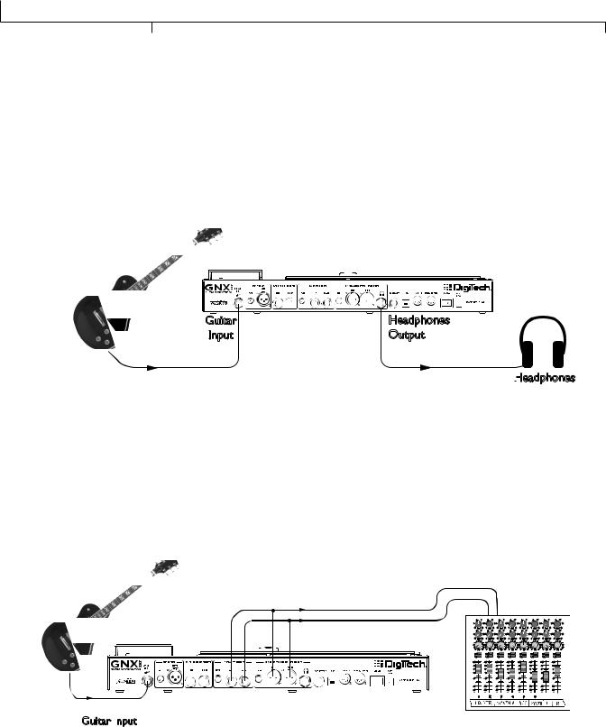
Headphones
This setup is ideal for practicing when neighbors, roommates or significant others don’t want to listen. Plug your guitar into the GUITAR INPUT and plug your headphones into the HEADPHONE OUTPUT. Note that the HEADPHONE OUTPUT is a 1/4” jack, so if your headphones have an 1/8” jack, you’ll need an adapter (available at your local electronics store).Turn Speaker Compensation on for the XLR OUTPUTS (see page 24) which also enables it for the headphones.
Guitar |
Headphones |
Input |
Output |
Headphones
Mixer
To connect to a mixer, plug your guitar into the GUITAR INPUT, and connect the GNX3000’s LEFT and RIGHT XLR or 1/4” BALANCED OUTPUTS to your mixer’s left and right inputs.Turn Speaker Compensation on for the 1/4” and XLR OUTPUTS (see page 24).
|
|
|
|
|
|
|
|
|
|
|
Mixer |
|
|
|
|
|
|
|
|
|
|||||||||
|
4 |
|
6 |
|
4 |
|
6 |
|
|
4 |
6 |
4 |
|
6 |
|
4 |
|
6 |
|
4 |
|
6 |
4 |
|
6 |
|
|
4 |
6 |
|
2 |
|
|
8 |
2 |
|
|
8 |
2 |
|
8 |
2 |
|
|
8 |
2 |
|
|
8 |
2 |
|
8 |
2 |
|
|
8 |
2 |
|
8 |
or |
0 |
Aux 1 |
10 |
0 |
Aux 1 |
10 |
0 |
Aux 1 |
10 |
0 |
Aux 1 |
10 |
0 |
Aux 1 |
10 |
0 |
Aux 1 |
10 |
0 |
Aux 1 |
10 |
0 |
Aux 1 |
10 |
|||||
0 -1Aux0 |
2+110 |
0 -1Aux0 |
2+110 |
0 |
-1Aux0 2+110 |
0 -1Aux0 |
2+110 |
0 -1Aux0 |
2+110 |
0 -1Aux0 2+110 |
0 -1Aux0 |
2+110 |
0 |
-1Aux0 2+110 |
|||||||||||||||
|
4 |
|
6 |
|
4 |
|
6 |
|
|
4 |
6 |
4 |
|
6 |
|
4 |
|
6 |
|
4 |
|
6 |
4 |
|
6 |
|
|
4 |
6 |
|
2 |
|
|
8 |
2 |
|
|
8 |
2 |
|
8 |
2 |
|
|
8 |
2 |
|
|
8 |
2 |
|
8 |
2 |
|
|
8 |
2 |
|
8 |
|
-2 |
|
|
+2 |
-2 |
|
|
+2 |
-2 |
|
+2 |
-2 |
|
|
+2 |
-2 |
|
|
+2 |
-2 |
|
+2 |
-2 |
|
|
+2 |
-2 |
|
+2 |
|
-3 |
|
|
+3 -3 |
|
|
+3 -3 |
|
+3 -3 |
|
|
+3 -3 |
|
|
+3 -3 |
|
+3 -3 |
|
|
+3 -3 |
|
+3 |
|||||||
|
-4 |
|
|
+4 |
-4 |
|
|
+4 |
-4 |
|
+4 |
-4 |
|
|
+4 |
-4 |
|
|
+4 |
-4 |
|
+4 |
-4 |
|
|
+4 |
-4 |
|
+4 |
|
-5 |
Pan |
|
+5 |
-5 |
Pan |
|
+5 |
-5 |
Pan |
+5 |
-5 |
Pan |
|
+5 |
-5 |
Pan |
|
+5 |
-5 |
Pan |
+5 |
-5 |
Pan |
|
+5 |
-5 |
Pan |
+5 |
|
Mute |
|
|
|
Mute |
|
|
|
Mute |
|
Mute |
|
|
|
Mute |
|
|
|
Mute |
|
|
Mute |
|
|
|
Mute |
|
||
|
L / R |
|
|
|
L / R |
|
|
|
L / R |
|
L / R |
|
|
|
L / R |
|
|
|
L / R |
|
|
L / R |
|
|
|
L / R |
|
||
|
+10 |
|
|
|
+10 |
|
|
|
+10 |
|
|
+10 |
|
|
|
+10 |
|
|
|
+10 |
|
|
+10 |
|
|
|
+10 |
|
|
|
+5 |
|
|
|
+5 |
|
|
|
+5 |
|
|
+5 |
|
|
|
+5 |
|
|
|
+5 |
|
|
+5 |
|
|
|
+5 |
|
|
|
0 |
|
|
|
0 |
|
|
|
0 |
|
|
0 |
|
|
|
0 |
|
|
|
0 |
|
|
0 |
|
|
|
0 |
|
|
|
-5 |
|
|
|
-5 |
|
|
|
-5 |
|
|
-5 |
|
|
|
-5 |
|
|
|
-5 |
|
|
-5 |
|
|
|
-5 |
|
|
|
-10 |
|
|
|
-10 |
|
|
|
-10 |
|
|
-10 |
|
|
|
-10 |
|
|
|
-10 |
|
|
-10 |
|
|
|
-10 |
|
|
|
-20 |
|
|
|
-20 |
|
|
|
-20 |
|
|
-20 |
|
|
|
-20 |
|
|
|
-20 |
|
|
-20 |
|
|
|
-20 |
|
|
|
-30 |
|
|
|
-30 |
|
|
|
-30 |
|
|
-30 |
|
|
|
-30 |
|
|
|
-30 |
|
|
-30 |
|
|
|
-30 |
|
|
|
- |
|
|
|
- |
|
|
|
- |
|
|
- |
|
|
|
- |
|
|
|
- |
|
|
- |
|
|
|
- |
|
|
|
|
1 |
|
|
|
2 |
|
|
|
3 |
|
|
4 |
|
|
|
5 |
|
|
|
6 |
|
|
|
|
|
|
|
|
Guitar Input
|
|
GNX3000 Owner’s Manual |
4 |
|
|
GNX3000 Owner’s Manual
Selecting Presets and Amp Models
Once you’re connected to the GNX3000, you can immediately transform the tone of your guitar with the 130 Factory presets. (There are also 65 User presets you can customize; learn how to create a custom preset on page 81.) Within each preset you can also select different amp models that will further alter your guitar’s tone.
Presets
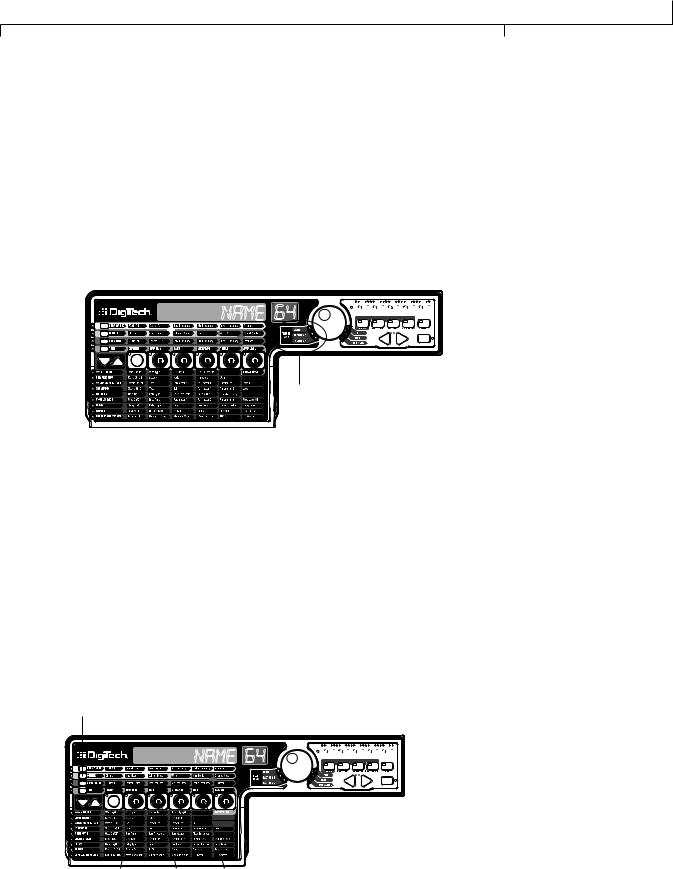
Turn the DATA WHEEL to scroll through the presets.The number and name in the
DISPLAYS change as you turn the DATA WHEEL.When you stop turning the DATA
WHEEL, the selected preset is automatically loaded. Play your guitar to hear it.
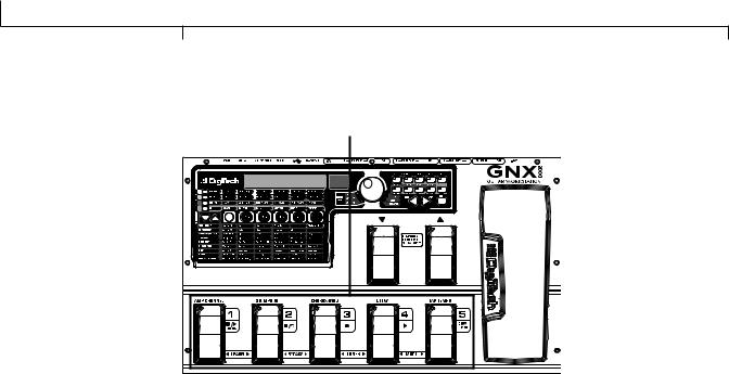
Data Wheel
NAME 64 


Preset Bank LEDs
Look at the Preset Bank LEDs to the left of the DATA WHEEL, and notice that either the User, Factory 1 or Factory 2 LED is lit.When you get to the end of one bank, you start at the beginning of the next bank.
Amp and Cabinet Models
You can choose and customize a virtual amp/cabinet combo to run your guitar signal through. (In this case,“amp” refers to the head, where all the knobs and tubes or electronics reside, and “cabinet” refers to the enclosure where the speakers are mounted.) For example, you can select the 62 bman amp model, which by default uses two 12-inch speakers in a Blonde cabinet (Blnd2x12). Then, if you want to, you can change the cabinet to a British model with four 12inch speakers (Brit4x12), which would result in the sound of a Bassman® head powering British speakers.
GENETX Button
NAME 64 


 Knob 5
Knob 1 Knob 2 Knob 4
|
|
5 |
GNX3000 Owner’s Manual |
|
|
Quick Start
To select an Amp and Cabinet model:
1.Push the GENETX BUTTON.
2.Turn KNOB 1 or KNOB 4 to select an amp model.
3.Turn KNOB 2 or KNOB 5 to select a cabinet model.
See page 44 for more information about Amp/Cabinet modeling.
Recording - Computer
If you’re ready to start recording, here’s how to connect the GNX3000 to your computer.You’ll also need to install the included software; see page 101 for more information.
|
Computer |
|
|
Powered Studio Monitor |
USB Cable |
Powered Studio Monitor |
|
|
|
|
|
Microphone |
|
|
Audio |
|
|
MIDI |
|
|
|
|
MIDI Keyboard |
|
XLR |
|
|
Mic Input |
Balanced |
|
|
Outputs |
|
|
|
|
|
|
|
Guitar |
Line Inputs |
|
|
Input |
|
|
|
GNXFC Foot
 Controller
Headphones
 (Optional)
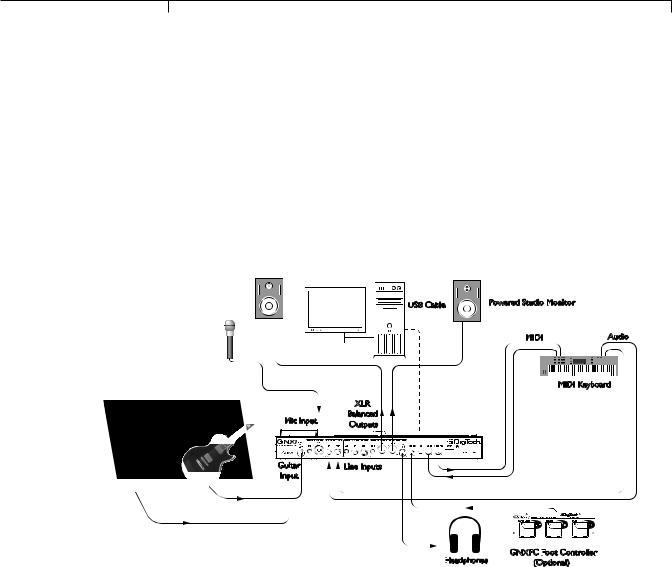
1.Connect your guitar (or bass guitar) to the GNX3000’s GUITAR INPUT.
2.Connect a microphone to the GNX3000’s MIC INPUT and use the MIC LEVEL control knob located next to the MIC INPUT on the GNX3000’s rear panel to adjust the microphone output level. To adjust your microphone input level for optimal use see Mic Level Optimization on page 26.
3.Connect a keyboard, line level instrument, or stereo mixer (for feeding submixes) to the GNX3000’s LEFT and RIGHT LINE INPUTS. To adjust your line input levels for optimal use see Line Level Optimization on page 26.
4.Connect XLR cables from the GNX3000’s LEFT and RIGHT XLR OUTPUTS
to powered studio monitors, OR connect a pair of stereo headphones to the
HEADPHONE OUTPUT.
5.Connect a GNXFC Foot Controller (optional) to the GNX3000’s FOOTSWITCH JACK.
|
|
GNX3000 Owner’s Manual |
6 |
|
|

GNX3000 Owner’s Manual
6.Connect the GNX3000 to your computer’s USB JACK using the included USB cable.
ATTENTION: Refer to the “Installing the GNX3000’s Software Suite” section on page 101 before connecting the GNX3000 to the USB port on your PC and using Pro Tracks
Plus.
7.Connect a MIDI keyboard to the GNX3000’s MIDI IN and OUT/THRU JACKS using 5 Pin MIDI cables.
8.Press the GNX3000’s OUTPUT SETUP button and select STEROALL as the output mode using the DATA WHEEL.
9.Turn Speaker Compensation on for the XLR OUTPUTS (see page 24).
See page 24 for more information about Speaker Compensation.
7GNX3000 Owner’s Manual
Highlights of the GNX3000
Highlights of the GNX3000
This section gives you a breakdown of the GNX3000’s main areas.
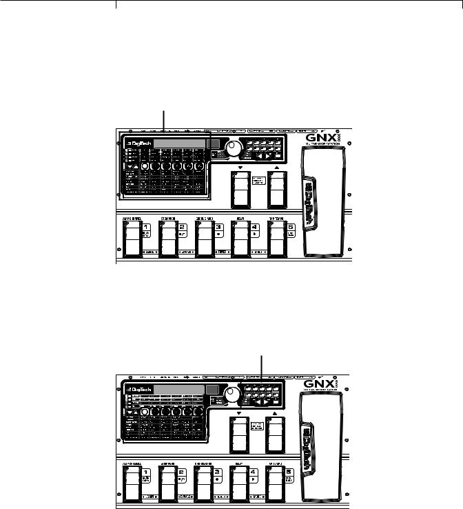
The Programming Matrix
Programming Matrix
This panel is divided into two main sections: the Amp/Cabinet section and the Effects section. If the Amp/Cabinet section is active, you can select and adjust amp and cabinet models and configurations. If the Effects section is active, you can select and adjust effects.The knobs adjust settings for whichever section is active.
The Control Panel
Control Panel
These buttons control several “nuts and bolts” operations of the GNX3000.You can use them to change the footswitch mode you’re in (page 36), choose output options (page 20), audio setup for recording (page 31), control the drum machine (page 99), save preset settings (page 92), and perform many other functions.
|
|
GNX3000 Owner’s Manual |
8 |
|
|
GNX3000 Owner’s Manual
The Expression Pedal
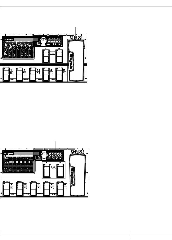
Expression Pedal
The EXPRESSION PEDAL can control up to three parameters at a time for any preset. For example, you could assign Chorus speed, Chorus depth, and volume to the EXPRESSION PEDAL so that they all increase when you rock it forward, and decrease when you rock it backward. See page 75 for more information about assigning functions to the EXPRESSION PEDAL.
You can turn the Wah pedal on or off by rocking the EXPRESSION PEDAL all the way forward (toe down), and pressing down firmly on the toe until WAH ON or WAH OFF appears in the display.
Down/Up Footswitches
Down/Up Footswitches
Depending on the mode, these footswitches select drum patterns or navigate through presets and preset banks. See page 36 for more on modes.
9GNX3000 Owner’s Manual
Highlights of the GNX3000
Footswitches 1-5 |
Footswitches 1-5 |
Depending on the mode, these five footswitches select presets, change amp channels, turn individual effects on and off, control drum machine operations, and give you Hands-FreeTM recording operation when recording on your computer. You can also press pairs of footswitches to activate the Learn-A-LickTM feature, bypass individual effects or the entire preset, access the tuner, or change the Footswitch modes.
|
|
GNX3000 Owner’s Manual |
10 |
|
|

GNX3000 Owner’s Manual
GNX3000 Special Features
This section describes some of the GNX3000’s unique characteristics in simple, easy- to-understand language and directs you to the pages where you can learn more about them.
Modes
The GNX3000 operates in one of three different modes.The active mode corresponds directly to what functions the footswitches control.The modes are called Preset, Stompbox, and Record/Drum.These modes are described in detail on page 36.The short description goes like this: Preset Mode lets you easily change between groups of presets; Stompbox Mode lets you change between individual presets and modify their settings with the FOOTSWITCHES; Record/Drum Mode gives you Hands-FreeTM control of the recording and drum machine functions.
To change modes, switch amp channels, and turn effects on and off, press the MODE button (to the right of the DATA WHEEL) or step on FOOTSWITCHES 4 and 5 simultaneously. Each time the mode is changed, the name of the new mode will be displayed briefly.
Amp Channels 1 and 2
Not only does the GNX3000 let you choose from a garage full of simulated amp head and cabinet combinations (page 44), you can set up two different combinations within the same preset and quickly switch back and forth between them.
For example, you can set up a Mesa/Boogie® Dual RectifierTM model amp on Channel 1 and a ‘65 Fender® Deluxe Reverb® amp model on Channel 2.You can play through either amp by switching channels with the AMP CHANNEL FOOTSWITCH (FOOTSWITCH 1) when the GNX3000 is in Stompbox Mode.
Amp Channel - Warped
A third channel can exist in addition to Channel 1 and Channel 2; we call this the Warped channel (yellow LED). Choose the Warped channel to hear a unique amp and cabinet combination based on the amps and cabinets assigned to the Channel 1 and Channel 2.
Refer to the Amp Channel Footswitch section on page 76 for more information.
HyperModels
A HyperModelTM is a custom user amp and cabinet model that is made by warping two different amp/cabinet combinations together.You can select a HyperModel like any other amp/cabinet model.
See page 81 for details about how to create a HyperModel; see page 44 for more on amp and cabinet models.
|
|
11 |
GNX3000 Owner’s Manual |
|
|

Getting Familiar with the GNX3000
Getting Familiar with the GNX3000
The Front Panel
1. Footswitches 1-5
Depending on the selected mode, these five FOOTSWITCHES select presets, change amp channels, turn individual effects on and off, and control drum machine and recording operations. Learn-A-LickTM, Bypass,Tuner and Mode functions are accessed by pressing the labeled pair of FOOTSWITCHES.
2. Effect Select Buttons
The  and
and  EFFECT SELECT buttons are used together with the Matrix LEDs to choose the effects you want to edit.
|
|
GNX3000 Owner’s Manual |
12 |
|
|
GNX3000 Owner’s Manual
3. Amp Control Buttons
The four AMP CONTROL buttons are used to select one of the amp/cabinet model edit rows including: CHAN ONE EQ (Green), GENETX (Yellow), CHAN TWO EQ
(Red), and TONE (Silver).
4. Status button
The STATUS button has multiple functions that depend on the matrix row that is selected. For example:
With the CHAN ONE EQ (Green) row selected, the STATUS button turns Channel
One’s EQ on and off.
With the GENETX (Yellow) amp/cabinet model row selected, the STATUS button selects which amp you are listening to: Channel One, Channel Two, or the Warped Amp (if a Warped state between both channels exists).
With the CHAN TWO EQ (Red) row selected, the STATUS button turns Channel
Two’s EQ on and off.
With the TONE (Silver) row selected, the STATUS button selects which amp you are listening to: Channel One, Channel Two, or the Warped Amp (if a Warped state between both channels exists).The Amp Gain, Bass, Midrange,Treble, and Amp Levels alternate between editing Channel One’s (lit green) or Channel Two’s (lit red) amp settings as the STATUS button is pressed.
When editing effects in the Effect Matrix, the STATUS button turns the selected effect on and off, or selects a controller type for the expression assignment.
5. Knobs 1-5
After selecting one of the rows using the AMP CONTROL or EFFECT SELECT buttons, these five knobs adjust the parameters listed in the column directly above or below each knob.
6.Matrix
a. GeNetX™ Amp Controls Matrix
The GeNetX Amp Controls Matrix lists the Channel One and Channel Two amp types, cabinet types, EQ/tone controls, and cabinet tuning parameters available for editing in each preset.
b. Effects Matrix
The Effects Matrix lists the effects and effect parameters available for editing in each preset.
|
|
13 |
GNX3000 Owner’s Manual |
|
|

Getting Familiar with the GNX3000
7. Displays
The Displays give feedback of the various functions that are being used in the GNX3000, including preset name, editing functions, tuner, utility menus, and drum machine settings.
8. Preset Bank LEDs
The Preset Bank LEDs indicate whether the selected preset resides in the User,
Factory 1, or Factory 2 banks.
9. Data Wheel
The DATA WHEEL is a multi-function control used for selecting presets and editing preset parameters. It is also used for adjusting the settings of the Drum Machine, Utilities, Output Setup, Mic/Line Routings, and Recording Setup menus.
10. Status Indicator LEDs (Clip, Wah, and USB Active)
There are three Status Indicator LEDs.The CLIP LED illuminates when one of the four input signals clip (is at or above their maximum input level),The WAH PEDAL LED lights when the Wah pedal is active.The USB LED lights when the USB connection is active.
11. Control Panel Buttons
The Control Panel buttons are used to select the GNX3000’s Footswitch Modes, Output Setups, and Utility functions, and to store Amp/Cabinet Model edits and Preset changes.They also access the GNX3000’s Drum Machine functions as well as mic/line routing and USB input source routing for recording.The buttons are labeled as follows:
MODE - This button changes the functionality of the DOWN/UP FOOTSWITCHES and FOOTSWITCHES 1-5 (see the Footswitch Functions for Modes section on page 94). Each time the mode is changed, the name of teh new mode is displayed briefly.
OUTPUT SETUP - This button selects one of the GNX3000 Audio Output Setups: Stereo All, Mono All, Mono 1/4”, Mono XLR, Split 1 and Split 2. Stereo and Mono All have all the input sources (guitar, mic, line inputs, drums, and audio playback from USB) routed to both output pairs in either stereo or mono respectively. Split 1 routes the guitar signal to just the 1/4” OUTPUTS while all other sources are routed out the XLR OUTPUTS. Split 2 is the same as Split 1 but the guitar signal is also routed out the XLR OUTPUTS. See page 24 for more information about Speaker Compensation for XLR and 1/4” OUTPUTS.
UTILITY - This button accesses the GNX3000’s global functions including:
Volume Pedal Update, Expression Pedal Calibration, Preset Bounceback, Bank
Naming, MIDI Channel selection, Sysex Bulk Dump, MIDI Preset Dump, User
|
|
GNX3000 Owner’s Manual |
14 |
|
|
GNX3000 Owner’s Manual
HyperModel™ Amp Dump, MIDI Mapping, MIDI Merge, USB Mode and Factory Reset (see the Utilities section on page 118).
AMP SAVE - This button stores Amp and Cabinet changes (tone, gain, level, amp type, cabinet type, warp, EQ or cabinet tuning) as HyperModelsTM.
STORE - This button is used to save Preset edits to the User Presets bank.


 (STOP/PLAY) DRUMS - This button is used to turn the General MIDI Drum Machine on and off. See page 99 for a list of drum patterns and page 128 for a list of samples.
PATTERN - Pressing this button and using the DATA WHEEL selects Drum machine patterns.
LEVEL - Pressing this button and using the DATA WHEEL adjusts the Drum
Machine output level.
TEMPO - Pressing this button and using the DATA WHEEL adjusts the Drum
Machine.
SHIFT - When this button is lit, the secondary functions labeled below each button are now active.
USB 1-2 SRC - Selects what input sources are to be recorded up the USB 1-2 channels.
USB 3-4 SRC - Selects what input sources are to be recorded up the USB 3-4 channels.
MIC - Selects the Mic Input Routing menu and how the mic signal is routed through the GNX3000’s effects processing for both recording and live performance.
LINE - Selects the Line Input Routing menu and how both LINE INPUTS are routed through the GNX3000’s effects processing for both recording and live performance.
USB 1-2 LVL - A gain/attenuation control to optimize the level of sources being recorded up the USB 1-2 channels.
USB 3-4 LVL - A gain/attenuation control to optimize the level of sources being recorded up the USB 3-4 channels.
|
|
15 |
GNX3000 Owner’s Manual |
|
|

Getting Familiar with the GNX3000
USB PLAY MIX - Controls the level balance between the GNX3000’s processing and the USB stream played back from your computer.This button is inactive when there is no active USB connection to a computer.The display will read NO USB if the button is pushed for this case.
NOTE:When connected to the computer it is possible to lose your audio input signal levels from the GUITAR, MIC, and/or LINE INPUTS if the USB Play/Mix control is all the way down (GNX mix = 0).
PREV/NEXT - Use these buttons to scroll through the active selection’s menus or values.
EXIT - Exits all functions back to the preset name display.
12. Down/Up Footswitches
These FOOTSWITCHES move up and down through the User preset banks (Preset Mode), navigate through presets (Stompbox Mode), and select drum patterns (Record/Drum Mode).
13. Expression Pedal
The EXPRESSION PEDAL controls up to three effect parameters in real time. Most GNX3000 parameters can be assigned to the EXPRESSION PEDAL.Applying extra pressure to the toe of the EXPRESSION PEDAL changes the EXPRESSION PEDAL’s function to control the Wah.
|
|
GNX3000 Owner’s Manual |
16 |
|
|
GNX3000 Owner’s Manual
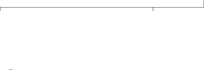
The Rear Panel
1 |
2 |
3 |
4 |
5 |
6 |
7 |
8 |
9 |
10 |
11 |
12 |
13 |
14 |
15 |
1. Guitar/Instrument Input
Connect your guitar/instrument to this jack.
2. Mic Level
Controls the gain of the MIC INPUT preamp.
3. Microphone Input
Connect a low impedance microphone to this jack for recording vocals or acoustic instruments. It can also be used for the Talker™ Vocoder effect (see Talker on page 57).The mic signal can remain dry or processed through the GNX3000’s effects for live and recording applications (see page 25 for more information).The Microphone Input is equipped with built-in phantom power (which is always on) for use with condenser or ribbon mics that require phantom power.
4. Left/Right Balanced Line Inputs
Connect line level sources to these jacks for recording or live performance mixing into the GNX3000. Line signals can remain dry or be processed through the GNX3000’s effects for live and recording applications (see page 25 for more information).
5. Output Level (1/4” Outputs Only)
Controls the overall volume level of the 1/4" OUTPUTS of the GNX3000.
6. Left/Right 1/4" Balanced Line Outputs
Connect these outputs to your guitar amplifier(s), power amplifier(s), or to a mixing console that accepts 1/4" balanced connections.
7. Output Level (XLR and Headphone Outputs Only)
Controls the overall volume level of the balanced XLR and HEADPHONE OUTPUTS of the GNX3000.
|
|
17 |
GNX3000 Owner’s Manual |
|
|

Getting Familiar with the GNX3000
8. Left/Right XLR Balanced Outputs
Connect these outputs to your power amplifier/speaker system or to a mixing console that accepts XLR balanced connections. DigiTech® recommends that you do not connect these GNX3000 XLR outputs to mixer or console channels that have phantom power enabled.
9. Headphone Output
Connect a pair of stereo headphones to this jack. DO NOT connect a mono plug to this jack, as it may damage the output driver.
10. Footswitch
(OPTIONAL ) Connect a GNXFC footswitch to this jack for remote control of the GNX3000’s record functions.
11. USB Jack
Connect this jack to your computer’s USB port for hard disk recording and computer preset editing via the X-Edit™ Editor/Librarian software.A standard USB cable is included.The GNX3000 is compatible with USB 2.0 high speed ports, however the USB 2.0 bus will switch to a USB v1.1 full speed (up to 12 Mbps) data rate to work with the GNX3000.
ATTENTION: Refer to the “Installing the GNX3000’s Software Suite” section on page
101 before connecting the GNX3000 to the USB port on your PC and using Pro Tracks
Plus.
12. MIDI In
The MIDI In jack receives all incoming MIDI data including MIDI preset changes. MIDI preset changes and CC control messages received from external MIDI devices connected to the MIDI In jack can be used to control the GNX3000 and its preset parameters. When the GNX3000 is connected to the computer
via USB, the MIDI In can be used as a MIDI interface for recording any MIDI data in Pro Tracks Plus™ or other MIDI recording software. (See page 129 for the MIDI CC table.)
13. MIDI Out/Thru
The MIDI Out/Thru jack sends MIDI data from the GNX3000 MIDI preset changes.When the GNX3000 is connected to the computer via USB, it can act as a MIDI interface for sending MIDI data from Pro Tracks Plus™ or other MIDI recording software to external keyboards or sound modules.When MIDI Merge is enabled in the Utility menu, the MIDI Out acts as a MIDI Thru for any data coming into the GNX3000 from the MIDI In jack. (See page 129 for the MIDI CC table.)
|
|
GNX3000 Owner’s Manual |
18 |
|
|

GNX3000 Owner’s Manual
14. Power Switch
Turns the power on and off.
15. Power Input
Connect only the provided DigiTech PSS3 power supply to this jack.
|
|
19 |
GNX3000 Owner’s Manual |
|
|
Audio Routing Setups
Audio Routing Setups
Setups Introduction
The GNX3000 is equipped with four inputs and four outputs that can be configured several different ways for both live and recording applications.These settings determine which pair of outputs the guitar processing, MIC and LINE INPUTS are routed to and how the MIC or LINE INPUTS are routed through the GNX3000’s effects processing. For example, today you may be practicing with headphones, tomorrow you may be recording on your computer, and next week you might be performing at a club, running your guitar and vocals through monitors and a PA system.The GNX3000 has different input/output options that are designed for each of those situations, and more.
Output Setups
The GNX3000 features both 1/4" and XLR OUTPUTS on the rear panel.These jacks let you simultaneously connect the GNX3000 to an amplifier/speaker system on stage via the 1/4" OUTPUTS and connect directly to your PA system via the XLR OUTPUTS.
Press the OUTPUT SETUP button and turn the DATA WHEEL to select one of the Output Setup options. Press the EXIT button to save your selection.
|
|
GNX3000 Owner’s Manual |
20 |
|
|
GNX3000 Owner’s Manual
The six OUTPUT SETUPS are as follows:
Stereo All ( steroall )
All input sources (guitar, mic, line inputs, drums, and USB playback) are routed to both output pairs in stereo. Speaker Compensation can be turned on and off
independently for either the 1/4” or XLR OUTPUTS using the Speaker Compensation menus (see page 24).
|
|
|
|
|
line fx |
|
|
|
|
|
|
|
|
|
|
|
|
|
|
|
|
|
line rvb |
|
|
line dry |
|||||||||||
Line Left |
|
|
|
|
|
|
|
|
|
|
|
|
|
|
|
|
|
|
|
|
|
|
|
|
|
|
|
|
|
|
|
|
|
|
|
|
|
|
|
|
|
|
|
|
|
|
|
|
|
|
|
|
|
|
|
|
|
|
|
|
|
|
|
|
|
|
|
|
|
|
|
|
|
DRUMS & |
|
Line Right |
|
|
|
|
|
|
|
|
|
|
|
|
|
|
|
|
|
|
|
|
|
|
|
|
|
|
|
|
|
|
|
|
|
|
USB PLAYBACK |
|
|
|
|
|
|
|
|
|
|
|
|
|
|
|
|
|
|
|
|
|
|
|
|
|
|
|
|
|
|
|
|
|
|
|
|
|
|
||
Mic Input |
|
|
|
|
mic fx |
|
|
|
|
|
|
|
|
|
|
|
|
|
|
|
|
|
mic rvb |
|
|
|
|
|
mic dry |
||||||||
|
|
|
|
|
|
|
|
|
|
|
|
|
|
|
|
|
|
|
|
|
|
|
|
|
|
|
|
|
|
|
|
|
|
XLR Left Output |
|||
|
|
|
|
|
|
|
|
|
|
|
|
|
|
|
|
|
|
|
|
|
|
|
|
|
+ |
|
|
|
|
|
|
|
+ |
|
|
||
Guitar Input |
|
+ |
|
|
Pickup |
|
Wah |
|
Comp |
|
Whammy/IPS |
|
Stompbox |
|
CH 1 Amp |
CH 1 |
|
Gate |
|
Whammy/IPS |
|
Chorus/ |
|
Delay |
|
Reverb |
SC |
|
|
|
|
||||||
|
|
|
Sim |
|
|
|
(except |
|
|
Modeling/ |
Cabinet |
|
|
(Talker) |
|
Mod |
|
+ |
|
SC |
|
|
|
|
+ |
XLR Right Output |
|||||||||||
|
|
|
|
|
|
|
|
|
|
|
|
|
Talker) |
|
|
|
Tone |
|
|
|
|
|
|
|
|
|
+ |
|
|
|
|||||||
|
|
|
|
|
|
|
|
|
|
|
|
|
|
|
|
|
|
|
|
|
|
|
|
|
|
|
|
|
|
||||||||
|
|
|
|
|
|
|
|
|
|
|
|
|
|
|
|
|
|
|
|
|
|
||||||||||||||||
|
|
|
|
|
|
|
|
|
|
|
|
|
|
|
|
|
|
|
|
|
|
|
|
|
|
|
|
|
|
|
|
|
|
|
1/4" Left Output |
||
|
|
|
|
|
|
|
|
|
|
|
|
|
|
|
|
|
CH 2 Amp |
CH 2 |
|
|
|
|
|
|
|
|
|
|
|
SC |
|
|
|
|
|||
|
|
|
|
|
|
|
|
|
|
|
|
|
|
|
|
|
Modeling/ |
Cabinet |
|
|
|
|
|
|
|
|
|
|
|
|
|
|
|
|
|
1/4" Right Output |
|
|
|
|
Comp |
|
Gate |
|
|
|
|
|
|
|
|
|
|
Tone |
|
|
|
|
|
|
|
|
|
|
|
|
SC |
+ |
|
|
|
||||
|
|
|
|
|
|
|
|
|
|
|
|
|
|
|
|
|
|
|
|
|
|
|
|
|
|
|
|
|
|
|
|
|
|
||||
|
|
|
Detector |
|
Detector |
|
|
|
|
|
|
|
|
|
|
|
|
|
|
|
|
|
|
|
|
|
|
|
|
|
|
|
|
|
|
||
SC = Speaker Compensation Module
Mono All ( mono all)
All input sources (guitar, mic, line inputs, drums, and USB playback) are routed to both output pairs in mono. Speaker Compensation can be turned on and off independently for either the 1/4” or XLR OUTPUTS using the Speaker Compensation menus (see page 24).
|
line fx |
line rvb |
line dry |
|||
Line Left |
|
|
|
|
|
|
|
|
|
|
|
|
|
|
|
|
|
|
DRUMS & |
|
Line Right |
|
|
|
|
USB PLAYBACK |
|
|
|
|
|
|
|
|
Mic Input |
mic fx |
mic rvb |
|
mic dry |
||
|
|
|
|
|
|
|
|
|
|
|
|
|
|
Guitar Input |
+ |
Pickup |
Wah |
Comp |
Whammy/IPS |
Stompbox |
CH 1 Amp |
CH 1 |
Gate |
Whammy/IPS |
Chorus/ + |
|
SC |
+ |
+ |
XLR Left Output |
Sim |
(except |
Modeling/ |
Cabinet |
(Talker) |
Mod |
Delay |
Reverb |
+ |
XLR Right Output |
|||||||
|
|
|
|
|
Talker) |
|
Tone |
|
|
|
|
+ |
SC |
|
||
|
|
|
|
|
|
|
CH 2 Amp |
CH 2 |
|
|
|
|
SC |
+ |
+ |
1/4" Left Output |
|
|
|
|
|
|
|
Modeling/ |
Cabinet |
|
|
|
|
|
+ |
1/4" Right Output |
|
|
Comp |
Gate |
|
|
|
|
Tone |
|
|
|
|
|
SC |
|
||
|
|
|
|
|
|
|
|
|
|
|
|
|
|
|
||
|
Detector |
Detector |
|
|
|
|
|
|
|
|
|
|
|
|
|
|
|
|
|
|
|
|
SC |
= Speaker Compensation Module |
|
|
|
|
|
||||
|
|
21 |
GNX3000 Owner’s Manual |
|
|
Audio Routing Setups
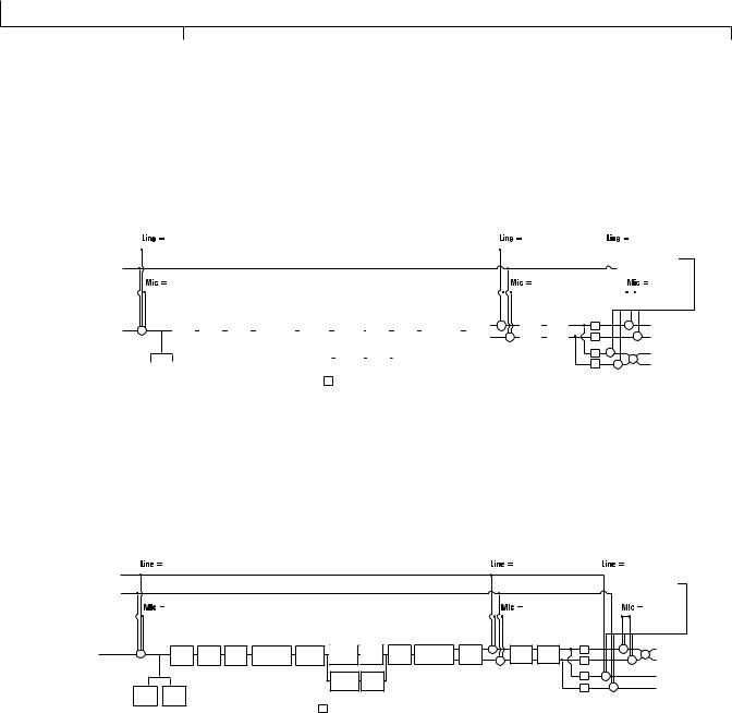
Mono 1/4 ( mono 1/4 )
All input sources (guitar, mic, line inputs, drums, and USB playback) are routed to the 1/4" OUTPUTS in mono.All input sources routed to the XLR OUTPUTS maintain stereo separation. Speaker Compensation can be turned on and off independently for either the 1/4” or XLR OUTPUTS using the Speaker Compensation menus (see page 24).
|
|
|
|
|
line fx |
|
|
|
|
|
|
|
|
|
|
|
|
|
|
|
|
|
line rvb |
|
|
|
|
line dry |
||||||||||||
Line Left |
|
|
|
|
|
|
|
|
|
|
|
|
|
|
|
|
|
|
|
|
|
|
|
|
|
|
|
|
|
|
|
|
|
|
|
|
|
|
|
|
|
|
|
|
|
|
|
|
|
|
|
|
|
|
|
|
|
|
|
|
|
|
|
|
|
|
|
|
|
|
|
|
|
|
|
|
|
|
DRUMS & |
|
|
Line Right |
|
|
|
|
|
|
|
|
|
|
|
|
|
|
|
|
|
|
|
|
|
|
|
|
|
|
|
|
|
|
|
|
|
|
|
USB PLAYBACK |
|
|||
|
|
|
|
|
|
|
|
|
|
|
|
|
|
|
|
|
|
|
|
|
|
|
|
|
|
|
|
|
|
|
|
|
|
|
|
|
|
|
||
Mic Input |
|
|
|
|
mic fx |
|
|
|
|
|
|
|
|
|
|
|
|
|
|
|
|
|
|
mic rvb |
|
|
|
|
|
|
|
mic dry |
||||||||
|
|
|
|
|
|
|
|
|
|
|
|
|
|
|
|
|
|
|
|
|
|
|
|
|
|
|
|
|
|
|
|
|
|
|
|
|
XLR Left Output |
|||
|
|
|
|
|
|
|
|
|
|
|
|
|
|
|
|
|
|
|
|
|
|
|
|
|
|
+ |
|
|
|
|
|
|
|
|
|
+ |
|
|
||
Guitar Input |
|
+ |
|
|
Pickup |
|
|
Wah |
|
Comp |
|
Whammy/IPS |
|
Stompbox |
|
CH 1 Amp |
CH 1 |
|
Gate |
|
Whammy/IPS |
|
Chorus/ |
|
Delay |
|
Reverb |
SC |
|
|
|
|
|
|
||||||
|
|
|
Sim |
|
|
|
|
(except |
|
|
Modeling/ |
Cabinet |
|
|
(Talker) |
|
Mod |
|
+ |
|
SC |
|
|
|
|
|
+ |
|
XLR Right Output |
|||||||||||
|
|
|
|
|
|
|
|
|
|
|
|
|
|
Talker) |
|
|
|
Tone |
|
|
|
|
|
|
|
|
|
|
|
+ |
|
|
|
|
|
|||||
|
|
|
|
|
|
|
|
|
|
|
|
|
|
|
|
|
|
|
|
|
|
|
|
|
|
|
|
|
|
|
|
|
|
|
|
|
|
1/4" Left Output |
||
|
|
|
|
|
|
|
|
|
|
|
|
|
|
|
|
|
|
CH 2 Amp |
CH 2 |
|
|
|
|
|
|
|
|
|
|
|
SC |
|
|
+ |
|
|
||||
|
|
|
|
|
|
|
|
|
|
|
|
|
|
|
|
|
|
Modeling/ |
Cabinet |
|
|
|
|
|
|
|
|
|
|
|
SC |
+ |
|
|
1/4" Right Output |
|||||
|
|
|
|
|
|
|
|
|
|
|
|
|
|
|
|
|
|
Tone |
|
|
|
|
|
|
|
|
|
|
|
|
|
|
|
|
||||||
|
|
|
Comp |
|
Gate |
|
|
|
|
|
|
|
|
|
|
|
|
|
|
|
|
|
|
|
|
|
|
|
|
|
|
|
|
|
|
|
|
|||
|
|
|
|
|
|
|
|
|
|
|
|
|
|
|
|
|
|
|
|
|
|
|
|
|
|
|
|
|
|
|
|
|
|
|
|
|
|
|||
|
|
|
Detector |
|
Detector |
|
|
|
|
|
|
|
SC |
= Speaker Compensation Module |
|
|
|
|
|
|
|
|
|
|
|
|
|
|
||||||||||||
|
|
|
|
|
|
|
|
|
|
|
|
|
|
|
|
|
|
|
|
|
|
|
|
|
|
|
|
|
|
|||||||||||
|
|
|
|
|
|
|
|
|
|
|
|
|
|
|
|
|
|
|
|
|
|
|
|
|
|
|
|
|
|
|
|
|||||||||
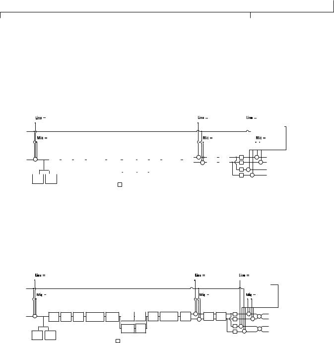
Mono XLR ( mono xlr )
All input sources (guitar, mic, line inputs, drums, and USB playback) are routed to the XLR OUTPUTS in mono.All input sources routed to the 1/4” OUTPUTS maintain stereo separation. Speaker Compensation can be turned on and off independently for either the 1/4” or XLR OUTPUTS using the Speaker Compensation menus (see page 24).
|
line fx |
line rvb |
line dry |
||
Line Left |
|
|
|
|
|
|
|
|
|
DRUMS & |
|
Line Right |
|
|
|
USB PLAYBACK |
|
mic fx |
|
|
|
|
|
mic rvb |
|
mic dry |
|||
Mic Input |
|
||||
|
|
|
|
|
|
|
|
|
|
|
|
Guitar Input |
+ |
Pickup |
Wah |
Comp |
Whammy/IPS |
Stompbox |
CH 1 Amp |
CH 1 |
Gate |
Whammy/IPS |
Chorus/ + |
|
SC |
|
+ |
+ |
XLR Left Output |
Sim |
(except |
Modeling/ |
Cabinet |
(Talker) |
Mod |
Delay |
Reverb |
|
+ |
XLR Right Output |
|||||||
|
|
|
|
|
Talker) |
|
Tone |
|
|
|
|
+ |
SC |
|
|
||
|
|
|
|
|
|
|
CH 2 Amp |
CH 2 |
|
|
|
|
SC |
+ |
|
|
1/4" Left Output |
|
|
|
|
|
|
|
Modeling/ |
Cabinet |
|
|
|
|
|
+ |
|
|
1/4" Right Output |
|
Comp |
Gate |
|
|
|
|
Tone |
|
|
|
|
|
SC |
|
|
||
|
|
|
|
|
|
|
|
|
|
|
|
|
|
|
|
||
|
Detector |
Detector |
|
|
|
|
|
|
|
|
|
|
|
|
|
|
|
|
|
|
|
|
|
SC |
= Speaker Compensation Module |
|
|
|
|
|
|
||||
|
|
GNX3000 Owner’s Manual |
22 |
|
|
 Loading...