


Before returning this product call
1-800-4-DeWALT
IF YOU SHOULD EXPERIENCE A PROBLEM WITH YOUR DeWALT PURCHASE,
CALL 1-800-4-DeWALT
IN MOST CASES, A DeWALT REPRESENTATIVE CAN RESOLVE YOUR PROBLEM OVER THE PHONE.
IF YOU HAVE A SUGGESTION OR COMMENT, GIVE US A CALL. YOUR FEEDBACK IS VITAL TO THE SUCCESS OF DeWALT’S QUALITY IMPROVEMENT PROGRAM.
Questions? Visit us at www.dewalt.com
Des questions ? Rendez nous visite à www.dewalt.com ¿Tiene preguntas? Visítenos en www.dewalt.com
INSTRUCTION MANUAL
GUIDE D’UTILISATION MANUAL DE INSTRUCCIONES
INSTRUCTIVO DE OPERACIÓN, CENTROS DE SERVICIO Y PÓLIZA DE GARANTÍA. ADVERTENCIA: LÉASE ESTE INSTRUCTIVO ANTES DE USAR EL PRODUCTO.
DHS790
12" (305 mm) 120V Max* Double Bevel Sliding Compound Miter Saw Scie coulissante à onglet mixte 305 mm (12 po), 120 V max* Sierra ingletadora compuesta deslizante de doble bisel de 305 mm (12") de 120 V Máx*
Final Print Size: 8.5" x 11"


Definitions: Safety Guidelines
This instruction manual uses the following safety alert symbols and words to alert you to hazardous situations and your risk of personal injury or property damage.
 DANGER: Indicates an imminently hazardous situation which, if not avoided, will result in death or serious injury.
 WARNING: Indicates a potentially hazardous situation which, if not avoided, could result in death or serious injury.
 CAUTION: Indicates a potentially hazardous situation which, if not avoided, may result in minor or moderate injury.
 (Used without word) Indicates a safety related message.
NOTICE: Indicates a practice not related to personal injury which, if not avoided, may result in property damage.
IF YOU HAVE ANY QUESTIONS OR COMMENTS ABOUT THIS OR ANY DeWALT TOOL, CALL US TOLL FREE AT: 1-800-4-DeWALT (1-800-433-9258).
 WARNING: To reduce the risk of injury, read the instruction manual.
Important Safety Instructions
WARNING! Read all safety warnings, instructions, illustrations and specifications provided with this power tool. Failure to follow all instructions listed below may result in electric shock, fire and/or serious injury.
SAVE ALL WARNINGS AND INSTRUCTIONS
FOR FUTURE REFERENCE
The term “power tool” in the warnings refers to your mains-operated (corded) power tool or battery-operated (cordless) power tool.
1) WORK AREA SAFETY
a)Keep work area clean and well lit. Cluttered or dark areas invite accidents.
b)Do not operate power tools in explosive atmospheres, such as in the presence of flammable liquids, gases or dust. Power tools create sparks which may ignite the dust or fumes.
c)Keep children and bystanders away while operating a power tool. Distractions can cause you to lose control.
2) ELECTRICAL SAFETY
a)Power tool plugs must match the outlet. Never modify the plug in any way. Do not use any adapter plugs with earthed (grounded) power tools. Unmodified plugs and matching outlets will reduce risk of electric shock.
b)Avoid body contact with earthed or grounded surfaces such as pipes, radiators, ranges and refrigerators. There is an increased risk of electric shock if your body is earthed or grounded.
c)Do not expose power tools to rain or wet conditions. Water entering a power tool will increase the risk of electric shock.
d)Do not abuse the cord. Never use the cord for carrying, pulling or unplugging the power tool. Keep cord away from heat, oil, sharp edges or moving parts. Damaged or entangled cords increase the risk of electric shock.
e)When operating a power tool outdoors, use an extension cord suitable for outdoor use. Use of a cord suitable for outdoor use reduces the risk of electric shock.
f)If operating a power tool in a damp location is unavoidable, use a residual current device (RCD) protected supply. Use of an RCD reduces the risk of electric shock.
3) PERSONAL SAFETY
a)Stay alert, watch what you are doing and use common sense when operating a power tool. Do not use a power tool while you are tired or under the influence of drugs, alcohol or medication. A moment of inattention while operating power tools may result in serious personal injury.
b)Use personal protective equipment. Always wear eye protection. Protective equipment such as dust mask, non-skid safety shoes, hardhat, or hearing protection used for appropriate conditions will reduce personal injuries.
c)Prevent unintentional starting. Ensure the switch is in the off position before connecting to power source and/or battery pack, picking up or carrying the tool.
Carrying power tools with your finger on the switch or energizing power tools that have the switch on invites accidents.
d)Remove any adjusting key or wrench before turning the power tool on. A wrench or a key left attached to a rotating part of the power tool may result in personal injury.
e)Do not overreach. Keep proper footing and balance at all times. This enables better control of the power tool in unexpected situations.
f)Dress properly. Do not wear loose clothing or jewelry. Keep your hair, clothing and gloves away from moving parts. Loose clothes, jewelry or long hair can be caught in moving parts.
g)If devices are provided for the connection of dust extraction and collection facilities, ensure these are connected and properly used. Use of dust collection can reduce dust-related hazards.
h)Do not let familiarity gained from frequent use of tools allow you to become complacent and ignore tool safety principles. A careless action can cause severe injury within a fraction of a second.
4) POWER TOOL USE AND CARE
a)Do not force the power tool. Use the correct power tool for your application. The correct power tool will do the job better and safer at the rate for which it was designed.
b)Do not use the power tool if the switch does not turn it on and off. Any power tool that cannot be controlled with the switch is dangerous and must be repaired.
c)Disconnect the plug from the power source and/or the battery pack from the power tool before making any adjustments, changing accessories, or storing power tools. Such preventive safety measures reduce the risk of starting the power tool accidentally.
d)Store idle power tools out of the reach of children and do not allow persons unfamiliar with the power tool or these instructions to operate the power tool.
Power tools are dangerous in the hands of untrained users.
e)Maintain power tools. Check for misalignment or binding of moving parts, breakage of parts and any other condition that may affect the power tool’s operation. If damaged, have the power tool repaired before use. Many accidents are caused by poorly maintained power tools.
f)Keep cutting tools sharp and clean. Properly maintained cutting tools with sharp cutting edges are less likely to bind and are easier to control.
g)Use the power tool, accessories and tool bits etc., in accordance with these instructions taking into account the working conditions and the work to be performed. Use of the power tool for operations different from those intended could result in a hazardous situation.
5) BATTERY TOOL USE AND CARE
a)Recharge only with the charger specified by the manufacturer. A charger that is suitable for one type of battery pack may create a risk of fire when used with another battery pack.
b)Use power tools only with specifically designated battery packs. Use of any other battery packs may create a risk of injury and fire.
English
1

English
c)When battery pack is not in use, keep it away from other metal objects like paper clips, coins, keys, nails, screws or other small metal objects that can make a connection from one terminal to another. Shorting the battery terminals together may cause burns or a fire.
d)Under abusive conditions, liquid may be ejected from the battery; avoid contact. If contact accidentally occurs, flush with water. If liquid contacts eyes, additionally seek medical help. Liquid ejected from the battery may cause irritation or burns.
e)Do not use a battery pack or tool that is damaged or modified. Damaged or modified batteries may exhibit unpredictable behavior resulting in fire, explosion or risk of injury.
f)Do not expose a battery pack or tool to fire or excessive temperature. Exposure to fire or temperature above 130 °C may cause explosion.
g)Follow all charging instructions and do not charge the battery pack or tool outside the temperature range specified in the instructions. Charging improperly or at temperatures outside the specified range may damage the battery and increase the risk of fire.
6) SERVICE
a)Have your power tool serviced by a qualified repair person using only identical replacement parts. This will ensure that the safety of the power tool is maintained.
b)Never service damaged battery packs. Service of battery packs should only be performed by the manufacturer or authorized service providers.
Safety Instructions for Miter Saws
a)Miter saws are intended to cut wood or wood-like products, they cannot be used with abrasive cut-off wheels for cutting ferrous material such as bars, rods, studs, etc. Abrasive dust causes moving parts such as the lower guard to jam. Sparks from abrasive cutting will burn the lower guard, the kerf insert and other plastic parts.
b)Use clamps to support the workpiece whenever possible. If supporting the workpiece by hand, you must always keep your hand at least 6" (152 mm) from either side of the saw blade. Do not use this saw to cut pieces that are too small to be securely clamped or held by hand. If your hand is placed too close to the saw blade, there is an increased risk of injury from blade contact.
c)The workpiece must be stationary and clamped or held against both the fence and the table. Do not feed the workpiece into the blade or cut “freehand” in any way. Unrestrained or moving workpieces could be thrown at high speeds, causing injury.
d)Push the saw through the workpiece. Do not pull the saw through the workpiece. To make a cut, raise the saw head and pull it out over the workpiece without cutting, start the motor, press the saw head down and push the saw through the workpiece. Cutting on the pull stroke is likely to cause the saw blade to climb on top of the workpiece and violently throw the blade assembly towards the operator.
e)Never cross your hand over the intended line of cutting either in front or behind the saw blade. Supporting the workpiece “cross handed” i.e. holding the workpiece to the right of the saw blade with your left hand or vice versa is very dangerous.
f)Do not reach behind the fence with either hand closer than 6" (152 mm) from either side of the saw blade, to remove wood scraps, or for any other reason while the blade is spinning. The proximity of the spinning saw blade to your hand may not be obvious and you may be seriously injured.
g)Inspect your workpiece before cutting. If the workpiece is bowed or warped, clamp it with the outside bowed face toward the fence. Always make certain that there is no gap between the workpiece, fence and table along the line of the cut.
Bent or warped workpieces can twist or shift and may cause binding on the spinning saw blade while cutting. There should be no nails or foreign objects in the workpiece.
h)Do not use the saw until the table is clear of all tools, wood scraps, etc., except for the workpiece. Small debris or loose pieces of wood or other objects that contact the revolving blade can be thrown with high speed.
i)Cut only one workpiece at a time. Stacked multiple workpieces cannot be adequately clamped or braced and may bind on the blade or shift during cutting.
j)Ensure the miter saw is mounted or placed on a level, firm work surface before use. A level and firm work surface reduces the risk of the miter saw becoming unstable.
k)Plan your work. Every time you change the bevel or miter angle setting, make sure the fence will not interfere with the blade or the guarding system. Without turning the tool “ON” and with no workpiece on the table, move the saw blade through a complete simulated cut to assure there will be no interference or danger of cutting the fence.
l)Provide adequate support such as table extensions, saw horses, etc. for a workpiece that is wider or longer than the table top. Workpieces longer or wider than the miter saw table can tip if not securely supported. If the cut-off piece or workpiece tips, it can lift the lower guard or be thrown by the spinning blade.
m)Do not use another person as a substitute for a table extension or as additional support. Unstable support for the workpiece can cause the blade to bind or the workpiece to shift during the cutting operation pulling you and the helper into the spinning blade.
n)The cut-off piece must not be jammed or pressed by any means against the spinning saw blade. If confined, i.e. using length stops, the cut-off piece could get wedged against the blade and thrown violently.
o)Always use a clamp or a fixture designed to properly support round material such as rods or tubing. Rods have a tendency to roll while being cut, causing the blade to “bite” and pull the work with your hand into the blade.
p)Let the blade reach full speed before contacting the workpiece. This will reduce the risk of the workpiece being thrown.
q)If the workpiece or blade becomes jammed, turn the miter saw off. Wait for all moving parts to stop and disconnect the plug from the power source and/ or remove the battery pack. Then work to free the jammed material. Continued sawing with a jammed workpiece could cause loss of control or damage to the miter saw.
r)After finishing the cut, release the switch, hold the saw head down and wait for the blade to stop before removing the cut-off piece. Reaching with your hand near the coasting blade is dangerous.
s)Hold the handle firmly when making an incomplete cut or when releasing the switch before the saw head is completely in the down position. The braking action of the saw may cause the saw head to be suddenly pulled downward, causing a risk of injury.
Additional Safety Rules for Miter Saws
 WARNING: Do not insert the battery into the unit or connect to a power source until complete instructions are read and understood.
•DO NOT OPERATE THIS MACHINE until it is completely assembled and installed according to the instructions. A machine incorrectly assembled can cause serious injury.
•OBTAIN ADVICE from your supervisor, instructor, or another qualified person if you are not thoroughly familiar with the operation of this machine. Knowledge is safety.
•FOLLOW ALL WIRING CODES and recommended electrical connections to prevent shock or electrocution. Protect electric supply line with at least a 15 ampere time-delay fuse or a circuit breaker.
•MAKE CERTAIN the blade rotates in the correct direction. The teeth on the blade should point in the direction of rotation as marked on the saw.
•TIGHTEN ALL CLAMP HANDLES, knobs and levers prior to operation. Loose clamps can cause parts or the workpiece to be thrown at high speeds.
•BE SURE all blade and blade clamps are clean, recessed sides of blade clamps are against blade and arbor screw is tightened securely. Loose or improper blade clamping may result in damage to the saw and possible personal injury.
2

•ONLY OPERATE WITH DeWALT FLEXVOLT BATTERIES OR WITH THE DeWALT CORDED POWER SUPPLY. Only connect the power supply cord to the designated voltage listed. Overheating, damage to the tool and personal injury may occur.
•DO NOT WEDGE ANYTHING AGAINST THE FAN to hold the motor shaft. Damage to tool and possible personal injury may occur.
•NEVER CUT FERROUS METALS (those with any iron or steel content) or masonry. Either of these can cause the carbide tips to fly off the blade at high speeds causing serious injury.
•DO NOT USE ABRASIVE WHEELS OR BLADES. The excessive heat and abrasive particles generated by them may damage the saw and cause personal injury.
•NEVER HAVE ANY PART OF YOUR BODY IN LINE WITH THE PATH OF THE SAW BLADE. Personal injury will occur.
•NEVER APPLY BLADE LUBRICANT TO A RUNNING BLADE. Applying lubricant could cause your hand to move into the blade resulting in serious injury.
•DO NOT place either hand in the blade area when the saw is connected to the power source. Inadvertent blade activation may result in serious injury.
•NEVER REACH AROUND OR BEHIND THE SAW BLADE. A blade can cause serious injury.
•DO NOT REACH UNDERNEATH THE SAW unless it is unplugged and turned off. Contact with saw blade may cause personal injury.
•SECURE THE MACHINE TO A STABLE SUPPORTING SURFACE. Vibration can possibly cause the machine to slide, walk, or tip over, causing serious injury.
•USE ONLY CROSSCUT SAW BLADES recommended for miter saws. For best results, do not use carbide tipped blades with hook angles in excess of 7 degrees. Do not use blades with deep gullets. These can deflect and contact the guard, and can cause damage to the machine and/or serious injury.
•USE ONLY BLADES OF THE CORRECT SIZE AND TYPE specified for this tool to prevent damage to the machine and/or serious injury.
•INSPECT BLADE FOR CRACKS or other damage prior to operation. A cracked or damaged blade can come apart and pieces can be thrown at high speeds, causing serious injury. Replace cracked or damaged blades immediately.
•CLEAN THE BLADE AND BLADE CLAMPS prior to operation. Cleaning the blade and blade clamps allows you to check for any damage to the blade or blade clamps. A cracked or damaged blade or blade clamp can come apart and pieces can be thrown at high speeds, causing serious injury.
•DO NOT USE WARPED BLADES. Check to see if the blade runs true and is free from vibration. A vibrating blade can cause damage to the machine and/or serious injury.
•DO NOT use lubricants or cleaners (particularly spray or aerosol) in the vicinity of the plastic guard. The polycarbonate material used in the guard is subject to attack by certain chemicals.
•KEEP GUARD IN PLACE and in working order.
•ALWAYS USE THE KERF PLATE AND REPLACE THIS PLATE WHEN DAMAGED.
Small chip accumulation under the saw may interfere with the saw blade or may cause instability of workpiece when cutting.
•USE ONLY BLADE CLAMPS SPECIFIED FOR THIS TOOL to prevent damage to the machine and/or serious injury.
•CLEAN THE MOTOR AIR SLOTS of chips and sawdust. Clogged motor air slots can cause the machine to overheat, damaging the machine and possibly causing a short which could cause serious injury.
•NEVER LOCK THE SWITCH IN THE “ON” POSITION. Severe personal injury may result.
•NEVER STAND ON TOOL. Serious injury could occur if the tool is tipped or if the cutting tool is unintentionally contacted.
•NEVER LEAVE TOOL RUNNING UNATTENDED. TURN POWER OFF. Don't leave tool until it comes to a complete stop.
•ADDITIONAL INFORMATION regarding the safe and proper operation of power tools (i.e., a safety video) is available from the Power Tool Institute, 1300 Sumner Avenue, Cleveland, OH 44115-2851 (www.powertoolinstitute.com). Information is also available from the National Safety Council, 1121 Spring Lake Drive, Itasca, IL 60143-3201. Please refer to the American National Standards Institute ANSI 01.1 Safety Requirements for Woodworking Machines and the U.S. Department of Labor OSHA 1910.213 Regulations.
 WARNING: Cutting plastics, sap coated wood, and other materials may cause melted material to accumulate on the blade tips and the body of the saw blade, increasing the risk of blade overheating and binding while cutting.
 WARNING: Always wear proper personal hearing protection that conforms to ANSI S12.6 (S3.19) during use. Under some conditions and duration of use, noise from this product may contribute to hearing loss.
 WARNING: ALWAYS use safety glasses. Everyday eyeglasses are NOT safety glasses. Also use face or dust mask if cutting operation is dusty. ALWAYS WEAR CERTIFIED SAFETY EQUIPMENT:
•ANSI Z87.1 eye protection (CAN/CSA Z94.3),
•ANSI S12.6 (S3.19) hearing protection,
•NIOSH/OSHA/MSHA respiratory protection.
 WARNING: Some dust created by power sanding, sawing, grinding, drilling, and other construction activities contains chemicals known to the State of California to cause cancer, birth defects or other reproductive harm. Some examples of these chemicals are:
•lead from lead-based paints,
•crystalline silica from bricks and cement and other masonry products, and
•arsenic and chromium from chemically-treated lumber.
Your risk from these exposures varies, depending on how often you do this type of work. To reduce your exposure to these chemicals: work in a well ventilated area, and work with approved safety equipment, such as those dust masks that are specially designed to filter out microscopic particles.
•Avoid prolonged contact with dust from power sanding, sawing, grinding, drilling, and other construction activities. Wear protective clothing and wash exposed areas with soap and water. Allowing dust to get into your mouth, eyes, or lay on the skin may promote absorption of harmful chemicals.
 WARNING: Use of this tool can generate and/or disperse dust, which may cause serious and permanent respiratory or other injury. Always use NIOSH/OSHA approved respiratory protection appropriate for the dust exposure. Direct particles away from face and body.
•The label on your tool may include the following symbols. The symbols and their definitions are as follows:
V...................... |
volts |
A.......................... |
amperes |
||||||
Hz.................... |
hertz |
W........................ |
watts |
||||||
min................... |
minutes |
|
|
|
or AC............. |
alternating current |
|||
|
|
|
or DC...... |
direct current |
|
|
|
or AC/DC...... |
alternating or direct |
|
|
|
|
|
|
||||
|
|
|
|
Class I Construction (grounded) |
no |
current |
|||
|
|
.................... |
|
||||||
|
|
|
|
||||||
|
|
.................... |
|
Class II Construction |
no load speed |
||||
|
|
|
|
(double insulated) |
n.......................... |
rated speed |
|||
…/min |
per minute |
|
|
|
|
earthing terminal |
|||
|
|
........................ |
|
||||||
|
|
|
|
||||||
BPM................ |
beats per minute |
|
|
......................... |
|
safety alert symbol |
|||
IPM.................. |
impacts per minute |
SPM................... |
strokes per minute |
||||||
RPM................ |
revolutions per minute |
sfpm.................... |
surface feet per minute |
||||||
|
|
.................... |
|
visible radiation |
|
|
........................ |
|
wear eye protection |
|
|
.................... |
|
wear respiratory protection |
|
|
........................ |
|
wear hearing protection |
English
3

English
For your convenience and safety, the following warning labels are on your miter saw.
ON MOTOR HOUSING:
 WARNING: TO REDUCE THE RISK OF INJURY, USER MUST READ INSTRUCTION MANUAL BEFORE OPERATING MITER SAW.
WHEN SERVICING, USE ONLY IDENTICAL REPLACEMENT PARTS. DO NOT EXPOSE TO RAIN OR USE IN DAMP LOCATIONS. ALWAYS USE PROPER EYE AND RESPIRATORY PROTECTION.
ON MOVING FENCES:
ALWAYS ADJUST FENCE PROPERLY BEFORE USE. CLAMP SMALL PIECES BEFORE CUTTING. SEE MANUAL.
ON GUARD:
DANGER–KEEP AWAY FROM BLADE.
ON UPPER GUARD:
PROPERLY SECURE BRACKET WITH BOTH SCREWS BEFORE USE.
ON TABLE: (2 PLACES)
 WARNING: TO REDUCE THE RISK OF INJURY, USER MUST READ INSTRUCTION MANUAL BEFORE OPERATING MITER SAW. KEEP HANDS OUT OF PATH OF SAW BLADE. DO
NOT OPERATE SAW WITHOUT GUARDS IN PLACE. CHECK LOWER GUARD FOR PROPER CLOSING BEFORE EACH USE. ALWAYS TIGHTEN ADJUSTMENT KNOBS BEFORE USE. DO
NOT PERFORM ANY OPERATION FREEHAND. CLAMP SMALL PIECES BEFORE CUTTING. NEVER REACH IN BACK OF SAW BLADE. NEVER CROSS ARMS IN FRONT OF BLADE. TURN OFF TOOL AND WAIT FOR SAW BLADE TO STOP BEFORE MOVING WORKPIECE, CHANGING SETTINGS OR MOVING HANDS. REMOVE BATTERY PACK BEFORE ADJUSTING, CHANGING BLADE OR SERVICING. TO REDUCE THE RISK OF INJURY, RETURN CARRIAGE TO THE FULL REAR POSITION AFTER EACH CROSSCUT OPERATION. THINK! YOU CAN PREVENT ACCIDENTS.
ON BASE: (2 PLACES)
Electrical Connection
Be sure your power source agrees with the nameplate marking. 120 volts, AC means that your saw will operate on alternating current. Do not operate with DC power. A voltage decrease of 10 percent or more will cause a loss of power and overheating. All DeWALT tools are factory tested. If this tool does not operate, check the power supply.
This miter saw operates on either two 60V battery packs or by using the DeWALT corded power supply.
Using the Corded Power Supply
The DeWALT corded power supply is designed to Fig. 1 provide power for DeWALT 120V Max* FLEXVOLT cordless tools. Insert the corded power supply into the
miter saw battery slot (refer to Installing and Removing the Corded Power Supply) and plug the power supply into an AC outlet. The power supply will act as the power source to the tool. Your DeWALT corded power supply should only be used with
standard household 120 VAC, 60 Hz power or a 120 VAC 60Hz generator.
The corded power supply is suitable for use with both
grounded and double insulated 120V AC tools. When the power supply is utilized with a grounded tool, the tool inlet will be equipped with a ground prong that allows the ground path from the tool to connect to the power supply. When the power supply is used with this double insulated miter saw, no ground connection is made from the tool to the power supply as no ground connection is required.
Additional Specific Usage Instructions
The corded power supply may become warm to the touch during use. This is a normal condition and does not indicate a problem.
IMPORTANT. The power supply is not user serviceable. There are no user serviceable parts inside the power supply.
Servicing at an authorized service center is required to avoid damage to static sensitive internal components.
Batteries and Chargers
The battery pack is not fully charged out of the carton. Before using the battery pack and charger, read the safety instructions below and then follow charging procedures outlined. When ordering replacement battery packs, be sure to include the catalog number and voltage.
Your tool uses a DeWALT charger. Be sure to read all safety instructions before using your charger. Consult the chart at the end of this manual for compatibility of chargers and battery packs.
Important Safety Instructions for All Battery Packs
 WARNING: Read all safety warnings and all instructions for the battery pack, charger and power tool. Failure to follow the warnings and instructions may result in electric shock, fire and/or serious injury.
•Do not charge or use the battery pack in explosive atmospheres, such as in the presence of flammable liquids, gases or dust. Inserting or removing the battery pack from the charger may ignite the dust or fumes.
•Never force the battery pack into the charger. Do not modify the battery pack in any way to fit into a non-compatible charger as battery pack may rupture causing serious personal injury. Consult the chart at the end of this manual for compatibility of batteries and chargers.
•Charge the battery packs only in designated DeWALT chargers.
•DO NOT splash or immerse in water or other liquids.
•Do not store or use the tool and battery pack in locations where the temperature may reach or exceed 104 °F (40 °C) (such as outside sheds or metal buildings in summer). For best life store battery packs in a cool, dry location.
NOTE: Do not store the battery packs in a tool with the trigger switch locked on. Never tape the trigger switch in the ON position.
4

•Do not incinerate the battery pack even if it is severely damaged or is completely worn out. The battery pack can explode in a fire. Toxic fumes and materials are created when lithium ion battery packs are burned.
•If battery contents come into contact with the skin, immediately wash area with mild soap and water. If battery liquid gets into the eye, rinse water over the open eye for 15 minutes or until irritation ceases. If medical attention is needed, the battery electrolyte is composed of a mixture of liquid organic carbonates and lithium salts.
•Contents of opened battery cells may cause respiratory irritation. Provide fresh air. If symptoms persist, seek medical attention.
 WARNING: Burn hazard. Battery liquid may be flammable if exposed to spark or flame.
 WARNING: Fire hazard. Never attempt to open the battery pack for any reason. If the battery pack case is cracked or damaged, do not insert into the charger. Do not crush, drop or damage the battery pack. Do not use a battery pack or charger that has received a sharp blow, been dropped, run over or damaged in any way (e.g., pierced with a nail, hit with a hammer, stepped on). Damaged battery packs should be returned to the service center for recycling.
TRANSPORTATION
 WARNING: Fire hazard. Do not store or carry the battery pack so that metal objects can contact exposed battery terminals. For example, do not place the battery pack in aprons, pockets, tool boxes, product kit boxes, drawers, etc., with loose nails, screws, keys, etc. Transporting batteries can possibly cause fires if the battery terminals inadvertently come in contact with conductive materials such as keys, coins, hand tools and the like. The US Department of Transportation Hazardous Material Regulations (HMR) actually prohibit transporting batteries in commerce or on airplanes in carry-on baggage UNLESS they are properly protected from short circuits. So when transporting individual battery packs, make sure that the battery terminals are protected and well insulated from materials that could contact them and cause a short circuit.
SHIPPING THE DeWALT FLEXVOLT™ BATTERY
The DeWALT FLEXVOLT™ battery has two modes: Use and Shipping.
Use Mode: When the FLEXVOLT™ battery stands alone or is in a DeWALT 20V Max* product, it will operate as a 20V Max* battery. When the FLEXVOLT™ battery is in a 60V Max* or a 120V Max* (two 60V Max* batteries) product, it will operate as a 60V Max* battery.
Shipping Mode: When the cap is attached to the FLEXVOLT™ battery, the battery is in Shipping Mode. Strings of cells are electrically disconnected within the pack resulting in three batteries
with a lower Watt hour (Wh) rating as compared to one battery with a higher Watt hour rating. This increased quantity of three batteries
with the lower Watt hour rating can exempt the pack from certain shipping regulations that are imposed upon the higher Watt hour batteries.
The battery label indicates two Watt hour ratings (see example). Depending on how the battery is shipped, the appropriate Watt hour rating must be used to determine the applicable shipping requirements. If utilizing the shipping cap, the pack will be considered 3 batteries at the Watt hour rating indicated for “Shipping”. If shipping without the cap or in a tool, the pack will be considered one battery at the Watt hour rating indicated next to “Use”.
Example of Use and Shipping Label Marking
USE: 120 Wh Shipping: 3 x 40 Wh
Shipping Watt hour rating indicates 3 x 40 Wh, meaning 3 batteries of 40 Watt hours each. The Use Watt hour rating indicates 120 Watt hour (1 battery implied).
FUEL GAUGE BATTERY PACKS (FIG. 2)
Some DeWALT battery packs include a fuel gauge which consists of three green LED lights that indicate the level of charge remaining in the battery pack.
The fuel gauge is an indication of approximate levels of charge remaining in the battery pack according to the following indicators:


 75–100% charged


 51–74% charged


 < 50% charged


 Pack needs to be charged
To actuate the fuel gauge, press and hold the fuel gauge button (BB). A combination of the three green LED lights will illuminate designating the level of charge left. When the level of charge in the battery is below the usable limit, the fuel gauge will not illuminate and the battery will need to be recharged.
Fig. 2
BB
NOTE: The fuel gauge is only an indication of the charge left on the battery pack. It does not indicate tool functionality and is subject to variation based on product components, temperature and end-user application.
For more information regarding fuel gauge battery packs, please contact call 1-800-4-DeWALT (1-800-433-9258) or visit our website www.dewalt.com.
The RBRC® Seal
The RBRC® (Rechargeable Battery Recycling Corporation) Seal on the nickel
cadmium, nickel metal hydride or lithium-ion batteries (or battery packs) 


 indicates that the costs to recycle these batteries (or battery packs) at the end
 of their useful life have already been paid by DeWALT. In some areas, it is illegal
 to place spent nickel cadmium, nickel metal hydride or lithium-ion batteries
 in the trash or municipal solid waste stream and the Call 2 Recycle® program provides an environmentally conscious alternative.
Call 2 Recycle, Inc., in cooperation with DeWALT and other battery users, has established the program in the United States and Canada to facilitate the collection of spent nickel cadmium, nickel metal hydride or lithium-ion batteries. Help protect our environment and conserve natural resources by returning the spent nickel cadmium, nickel metal hydride or lithium-ion batteries to an authorized DeWALT service center or to your local retailer for recycling. You may also contact your local recycling center for information on where to drop off the spent battery. RBRC® is a registered trademark of Call 2 Recycle, Inc.
Important Safety Instructions for All Battery Chargers
 WARNING: Read all safety warnings and all instructions for the battery pack, charger and power tool. Failure to follow the warnings and instructions may result in electric shock, fire and/or serious injury.
English
5

English
•DO NOT attempt to charge the battery pack with any chargers other than the ones in this manual. The charger and battery pack are specifically designed to work together.
•These chargers are not intended for any uses other than charging DeWALT rechargeable batteries. Any other uses may result in risk of fire, electric shock
or electrocution.
•Do not expose the charger to rain or snow.
•Pull by the plug rather than the cord when disconnecting the charger. This will reduce the risk of damage to the electric plug and cord.
•Make sure that the cord is located so that it will not be stepped on, tripped over or otherwise subjected to damage or stress.
•Do not use an extension cord unless it is absolutely necessary. Use of improper extension cord could result in risk of fire, electric shock or electrocution.
•When operating a charger outdoors, always provide a dry location and use an extension cord suitable for outdoor use. Use of a cord suitable for outdoor use reduces the risk of electric shock.
•An extension cord must have adequate wire size (AWG or American Wire Gauge) for safety. The smaller the gauge number of the wire, the greater the capacity of the cable, that is, 16 gauge has more capacity than 18 gauge. An undersized cord will cause a drop in line voltage resulting in loss of power and overheating. When using more than one extension to make up the total length, be sure each individual extension contains at least the minimum wire size. The following table shows the correct size to use depending on cord length and nameplate ampere rating. If in doubt, use the next heavier gauge. The lower the gauge number, the heavier the cord.
|
|
|
Minimum Gauge for Cord Sets |
|
|
||
|
|
|
Volts |
Total Length of Cord in Feet (meters) |
|||
Ampere Rating |
|
120V |
25 (7.6) |
50 (15.2) |
100 (30.5) |
150 (45.7) |
|
|
|
|
240V |
50 (15.2) |
100 (30.5) |
200 (61.0) |
300 (91.4) |
More |
Not More |
|
|
|
AWG |
|
|
Than |
Than |
|
|
|
|
|
|
|
|
|
|
|
|
||
0 |
6 |
|
|
18 |
16 |
16 |
14 |
6 |
10 |
|
|
18 |
16 |
14 |
12 |
10 |
12 |
|
|
16 |
16 |
14 |
12 |
12 |
16 |
|
|
14 |
12 |
Not Recommended |
|
•Do not place any object on top of the charger or place the charger on a soft surface that might block the ventilation slots and result in excessive internal heat. Place the charger in a position away from any heat source. The charger is ventilated through slots in the top and the bottom of the housing.
•Do not operate the charger with a damaged cord or plug.
•Do not operate the charger if it has received a sharp blow, been dropped or otherwise damaged in any way. Take it to an authorized service center.
•Do not disassemble the charger; take it to an authorized service center when service or repair is required. Incorrect reassembly may result in a risk of electric shock, electrocution or fire.
•Disconnect the charger from the outlet before attempting any cleaning. This will reduce the risk of electric shock. Removing the battery pack will not reduce this risk.
•NEVER attempt to connect 2 chargers together.
•The charger is designed to operate on standard 120V household electrical power. Do not attempt to use it on any other voltage. This does not apply to the vehicular charger.
 WARNING: Shock hazard. Do not allow any liquid to get inside the charger. Electric shock may result.
 WARNING: Burn hazard. Do not submerge the battery pack in any liquid or allow any liquid to enter the battery pack. Never attempt to open the battery pack for any reason. If the plastic housing of the battery pack breaks or cracks, return to a service center for recycling.
 CAUTION: Burn hazard. To reduce the risk of injury, charge only DeWALT rechargeable battery packs. Other types of batteries may overheat and burst resulting in personal injury and property damage.
NOTICE: Under certain conditions, with the charger plugged into the power supply, the charger can be shorted by foreign material. Foreign materials of a conductive nature, such as, but not limited to, grinding dust, metal chips, steel wool, aluminum foil or any buildup of metallic particles should be kept away from the charger cavities. Always unplug the charger from the power supply when there is no battery pack in the cavity. Unplug the charger before attempting to clean.
Charging a Battery (Fig. 3)
Plug the charger into an appropriate outlet before inserting battery pack.
FIG. 3
Insert the battery pack into the charger, making sure the battery pack is fully seated in the charger. The red (charging) light will blink continuously indicating that the charging process has started.
The completion of charge will be indicated by the red light remaining ON continuously. The battery pack is fully charged and may be used at this time or left in the charger. To remove the battery pack from the charger, push the battery release button on the battery pack.
NOTE: To ensure maximum performance and life of lithium-ion battery packs, charge the battery pack fully before first use.
CHARGER OPERATION
Refer to the indicators below for the charge status of the battery pack.
DCB107, DCB112, DCB113, DCB115, DCB118, DCB132
Charging
Fully Charged
Hot/Cold Pack Delay*
*The red light will continue to blink, but a yellow indicator light will be illuminated during this operation. Once the battery pack has reached an appropriate temperature, the yellow light will turn off and the charger will resume the charging procedure.
The compatible charger(s) will not charge a faulty battery pack. The charger will indicate faulty battery pack by refusing to light or by displaying a problem pack or charger blink pattern.
6

NOTE: This could also mean a problem with a charger.
If the charger indicates a problem, take the charger and battery pack to be tested at an authorized service center.
HOT/COLD PACK DELAY
When the charger detects a battery pack that is too hot or too cold, it automatically starts a Hot/Cold Pack Delay, suspending charging until the battery pack has reached an appropriate temperature. The charger then automatically switches to the pack charging mode. This feature ensures maximum battery pack life.
A cold battery pack will charge at a slower rate than a warm battery pack. The battery pack will charge at that slower rate throughout the entire charging cycle and will not return to maximum charge rate even if the battery pack warms.
The DCB118 charger is equipped with an internal fan designed to cool the battery pack. The fan will turn on automatically when the battery pack needs to be cooled.
Never operate the charger if the fan does not operate properly or if ventilation slots are blocked. Do not permit foreign objects to enter the interior of the charger.
ELECTRONIC PROTECTION SYSTEM
Li-Ion tools are designed with an Electronic Protection System that will protect the battery pack against overloading, overheating or deep discharge.
The tool will automatically turn off if the Electronic Protection System engages. If this occurs, place the lithium-ion battery pack on the charger until it is fully charged.
Wall Mounting
These chargers are designed to be wall mountable or to sit upright on a table or work surface. If wall mounting, locate the charger within reach of an electrical outlet, and away from a corner or other obstructions which may impede air flow. Use the back of the charger as a template for the location of the mounting screws on the wall. Mount the charger securely using drywall screws (purchased separately) at least 1" (25.4 mm) long, with a screw head diameter of 0.28–0.35" (7–9 mm), screwed into wood to an optimal depth leaving approximately 7/32" (5.5 mm) of the screw exposed. Align the slots on the back of the charger with the exposed screws and fully engage them in the slots.
Charger Cleaning Instructions
 WARNING: Shock hazard. Disconnect the charger from the AC outlet before cleaning. Dirt and grease may be removed from the exterior of the charger using a cloth or soft nonmetallic brush. Do not use water or any cleaning solutions.
Important Charging Notes
1.Longest life and best performance can be obtained if the battery pack is charged when the air temperature is between 65 °F and 75 °F (18 ° – 24 °C). DO NOT charge the battery pack in an air temperature below +40 °F (+4.5 °C), or above +104 °F (+40 °C). This is important and will prevent serious damage to the battery pack.
2.The charger and battery pack may become warm to the touch while charging. This is a normal condition, and does not indicate a problem. To facilitate the cooling of the battery pack after use, avoid placing the charger or battery pack in a warm environment such as in a metal shed or an uninsulated trailer.
3.If the battery pack does not charge properly:
a.Check operation of receptacle by plugging in a lamp or other appliance;
b.Check to see if receptacle is connected to a light switch which turns power off when you turn out the lights;
c.Move the charger and battery pack to a location where the surrounding air temperature is approximately 65 °F – 75 °F (18 ° – 24 °C);
d.If charging problems persist, take the tool, battery pack and charger to your local service center.
4.The battery pack should be recharged when it fails to produce sufficient power on jobs which were easily done previously. DO NOT CONTINUE to use under these conditions. Follow the charging procedure. You may also charge a partially used pack whenever you desire with no adverse effect on the battery pack.
5.Foreign materials of a conductive nature such as, but not limited to, grinding dust, metal chips, steel wool, aluminum foil, or any buildup of metallic particles should be kept away from charger cavities. Always unplug the charger from the power supply when there is no battery pack in the cavity. Unplug the charger before attempting to clean.
6.Do not freeze or immerse the charger in water or any other liquid.
Storage Recommendations
1.The best storage place is one that is cool and dry, away from direct sunlight and excess heat or cold.
2.For long storage, it is recommended to store a fully charged battery pack in a cool dry place out of the charger for optimal results.
NOTE: Battery packs should not be stored completely depleted of charge. The battery pack will need to be recharged before use.
SAVE THESE INSTRUCTIONS FOR FUTURE USE
Unpacking Your Saw
Check the contents of your miter saw carton to make sure that you have received all parts. In addition to this instruction manual, the carton should contain:
1 DHS790 miter saw
1DeWALT 12" (305 mm) diameter saw blade May include:
1DeWALT Corded power supply
260V batteries
1 Dual port charger In bag:
1 Blade wrench
1 Material clamp
1 Dustbag
1 Instruction manual
Specifications
CAPACITY OF CUT
50º miter left, 60º miter right, 49º bevel left and right
ANGLE |
MAXIMUM CAPACITY OF CUT |
RESULT |
|
||
0° miter |
Height |
4.4" (112 mm) |
Width |
9.1" (231 mm) |
|
Width |
13.75" (349 mm) |
Height |
3.0" (76 mm) |
||
|
|||||
|
|
|
|
|
|
45° miter |
Height |
4.4" (112 mm) |
Width |
5.8" (147 mm) |
|
Width |
9.6" (244 mm) |
Height |
3.0" (76 mm) |
||
|
|||||
|
|
|
|
|
|
45º bevel – left |
Height |
3.1" (79 mm) |
Width |
11.4" (290 mm) |
|
Width |
13.75" (349 mm) |
Height |
1.7" (43 mm) |
||
|
|||||
|
|
|
|
|
|
45º bevel – right |
Height |
2.2" (56 mm) |
Width |
11.4" (290 mm) |
|
Width |
13.75" (349 mm) |
Height |
1.1" (28 mm) |
||
|
|||||
|
|
|
|
|
|
English
7

English
FIG. 4 |
A |
|
B |
C
S
D
R
Q 
P O 
N
E
|
|
|
E |
M |
|
|
AA |
|
|
|
Y |
E |
K |
L J |
I H G F |
T
V
W
U
X
Z
Your saw is capable of cutting baseboard moldings held vertically 0.8" (20 mm) thick by 6.75" (171 mm) tall on a 45º right or left miter, when using the slide lock lever (AN, Fig. 10).
NOTE: Your saw is capable of cutting the following once a special setup procedure is followed. Refer to Special Cuts.
0° miter |
Height 1.5" (38 mm) |
Width 16.1" (409 mm) |
45º miter |
Height 1.5" (38 mm) |
Width 11.7" (297 mm) |
Familiarization |
|
FIG. 5 |
|
|
Your miter saw is fully assembled in the carton. Open the box and lift the saw out by the convenient lifting handle, as shown in Figure 5. Place the saw on a smooth, flat surface such as a workbench, strong table or DeWALT miter saw stand. Examine Figure 4 to become familiar with the saw and its various parts. The section on adjustments will refer to these terms and you must know what and where the parts are.
 CAUTION: Pinch Hazard. To reduce the risk of injury, keep thumb underneath the operating handle (A) when pulling the handle down. The lower guard will move up as the handle is
pulled down which could cause pinching. The handle is placed close to the guard for special cuts.
Press down lightly on the operating handle and pull out the lock down pin (Q, Fig. 4). Gently release the downward pressure and hold the arm allowing it to rise to its full height. Use the lock down pin when carrying the saw from one place to another. Always use the carrying handle to transport the saw or the hand indentations (M, Fig. 4).
COMPONENTS (Fig. 4)
 WARNING: Never modify the power tool or any part of it. Damage or personal injury could result.
A. |
Operating handle |
K. |
Miter scale |
T. |
Battery packs |
B. |
Trigger switch |
L. |
Miter scale screws |
U. |
Rails |
C. |
Trigger lock-off button |
M. |
Hand indentations |
V. |
Rail lock knob |
D. |
Lower guard |
N. |
Fence |
W. |
Rail adjustment screw |
E. |
Mounting holes |
O. |
Bevel scale |
X. |
Dust port |
F. |
Miter lock lever |
P. |
Bevel scale pointer |
Y. |
Hex wrench |
G. |
Miter release button |
Q. |
Lock down pin |
Z. |
Bevel lock knob |
H. |
Miter detent override lever |
R. |
Lifting handle |
AA. Clamp hole |
|
I. |
Kerf plate |
S. |
CUTLINE™ worklight |
|
|
J. |
Miter scale pointer |
|
switch |
|
|
8
INTENDED USE
This miter saw is designed for professional sawing applications.
DO NOT use under wet conditions or in presence of flammable liquids or gases.
This miter saw is a professional power tool. DO NOT let children come into contact with the tool. Supervision is required when inexperienced operators use this tool.
Transporting and Storing the Saw (Fig. 4, 7)
 WARNING: To reduce the risk of serious personal injury, turn tool off and remove the battery packs or power supply before transporting, making any adjustments, cleaning, repairing, or removing/installing attachments or accessories. An accidental start-up can cause injury.
 WARNING: To reduce the risk of serious personal injury, ALWAYS lock the rail lock knob (V), miter lock lever (F), bevel lock knob (Z), lock down pin (Q) and fence adjustment knobs (AZ, Fig. 7) before transporting saw.
In order to conveniently carry the miter saw from place to place, a lifting handle (R) has been included on the top of the saw arm and hand indentations (M) in the base.
HEAD LOCK DOWN PIN (FIG. 4)
 WARNING: The lock down pin should be used ONLY when carrying or storing the saw. NEVER use the lock down pin for any cutting operation.
To lock the saw head in the down position, push the head down, push the lock down pin (Q) in and release the saw head. This will hold the saw head safely down for moving the saw from place to place. To release, press the saw head down and pull the pin out.
FEATURES AND CONTROLS
 WARNING: To reduce the risk of serious personal injury, turn tool off and remove the battery packs or power supply before transporting, making any adjustments, cleaning, repairing, or removing/installing attachments or accessories. An accidental start-up can cause injury.
USE OF CUTLINE™ LED WORKLIGHT (FIG. 4)
 CAUTION: Do not stare into worklight. Serious eye injury could result.
The CUTLINE™ LED Worklight can be turned on by the momentary switch (S). The light will automatically turn off within 20 seconds if the saw is not in use. The light is also activated automatically every time the tool's main trigger (B) is pulled.
To cut through an existing pencil line on a piece of wood, turn on the CUTLINE™ worklight using the momentary switch (S) (not with the main trigger), then pull down on the operating handle (A) to bring the saw blade close to the wood. The shadow of the blade will appear on the wood. This shadow line represents the material that the blade will remove when performing a cut. To correctly locate your cut to the pencil line, align the pencil line with the edge of the blade’s shadow. Keep in mind that you may have to adjust the miter or bevel angles in order to match the pencil line exactly.
Your saw is equipped with a battery monitoring feature. The CUTLINE™ worklight begins to flash when the battery is near the end of its useful charge and/or when the battery is too hot. Charge the battery prior to continuing cutting applications. Refer to Charging Procedure under Important Safety Instructions for All Battery Packs for battery charging instructions.
MITER CONTROL (FIG. 6)
The miter lock lever and miter release button allow you to miter your saw to 60° right and 50° left. To miter the saw, lift the miter lock lever (F), push the miter release button (G) and move the miter arm to the angle desired on the miter scale (K) as shown at the miter scale pointer
(J). Push down on the miter lock lever to lock the miter arm in place.
FIG. 6
L K J H G F
MITER DETENT OVERRIDE (FIG. 6)
The miter detent override lever (H) allows your saw to override the common stop angles (detents).
To override the detents, unlock the miter lock lever (F) by pulling upward. Push the miter detent override lever (H) up, and move the miter arm to the angle desired on the miter scale
(K). Push down on the miter lock lever to lock the miter arm in place.
BEVEL LOCK (FIG. 7)
The bevel lock allows you to bevel the saw 49° left or right. To adjust the bevel setting, turn the bevel lock knob (Z) counterclockwise. The saw head will then bevel easily to the left or to the right. To tighten, turn the bevel lock knob clockwise.
0° BEVEL OVERRIDE (FIG. 7)
The bevel override allows you to bevel the saw to the right, past the 0° mark.
When the 0° bevel override lever (AB) is engaged (the lever will be turned up), the saw will automatically stop at 0° when brought up from the left. To move past 0° to the right, bevel the saw slightly to the left of 0°, then pull the 0° bevel override lever (AB) out. The saw head can now be beveled past 0° to the right. Lock the saw head at the desired angle by turning the bevel lock knob (Z) clockwise to tighten. The 0° bevel override lever can be locked out by twisting the lever so it faces down.
FIG. 7
N
 AZ
AZ
AZ |
AB |
|
|
|
AC |
|
AC |
|
Z |
English
9

English
45° BEVEL OVERRIDE (FIG. 7)
There are two 45° bevel override levers (AC), one on each side of the saw. To bevel the saw, left or right, past 45°, push the 45° bevel override lever (AC) rearward. When in the rearward position, the saw can bevel past these stops. When the 45° stops are needed, pull the 45°
bevel override lever forward.
CROWN BEVEL PAWLS (FIG. 8)
When cutting crown molding laying flat, your saw is equipped to accurately and rapidly set a crown stop, left or right (refer to Instructions for Cutting Crown Molding Laying Flat and Using the Compound Features under Cutting Crown Molding). The 33.9° crown bevel pawl (AD) can be rotated to contact the crown adjustment screw (AF). The saw is factory set to be used for typical crown in North America (52/38), but can be reversed to cut non-typical (45/45) crown. To reverse the 33.9° crown bevel pawl, remove the retaining screw (AG), the 22.5° bevel pawl (AE) and the 33.9° crown bevel pawl (AD). Flip the 33.9° crown bevel pawl so the 30° text is facing up. Reattach the screw to secure the 22.5° bevel pawl and the crown bevel pawl. The accuracy setting will not be affected.
FIG. 8
AJ
P
O
AI
AF
AB
AE
AG 
AD 
AH 
22.5° BEVEL PAWLS (FIG. 8)
Your saw is equipped to rapidly and accurately set a 22.5° bevel, left or right. The 22.5° bevel pawl (AE) can be rotated to contact the crown adjustment screw (AF).
RAIL LOCK KNOB (FIG. 4)
The rail lock knob (V) allows you to lock the saw head firmly to keep it from sliding on the rails. This is necessary when making certain cuts or when transporting the saw.
DEPTH STOP (FIG. 9)
The depth stop allows the depth of cut of the blade to be limited. The stop is useful for applications such as grooving and tall vertical cuts. Rotate the depth stop (AK) forward and adjust the depth adjustment screw (AL) to set the desired depth of cut. To secure the adjustment, tighten the wing nut (AM). Rotating the depth stop to the rear of the saw will bypass the depth stop feature. If the depth adjustment screw is too tight to loosen by hand, the provided blade wrench can be used to loosen the screw.
FIG. 9
AM  AL
AL
AK 
SLIDE LOCK LEVER (FIG. 10)
The slide lock lever (AN) places the saw in a position to maximize FIG. 10 cutting of base molding when cut vertically as shown in
Figure 25.
AUTOMATIC ELECTRIC BLADE BRAKE
Your saw is equipped with an automatic electric blade brake which stops the saw blade within 5 seconds of trigger release. This is not adjustable. On rare occasions the brake may not engage and the blade will coast to a stop. If this occurs, wait for several minutes before continuing use. If the condition
persists, there may be a fault condition. Have the tool serviced AN by an authorized DeWALT service center.
Always be sure the blade has stopped before raising the arm and removing the blade from the kerf plate. The brake is not a substitute for guards. Ensure your own safety by giving the saw your complete attention.
GUARD ACTUATION AND VISIBILITY
 CAUTION: Pinch Hazard. To reduce the risk of injury, keep thumb underneath the handle when pulling the handle down. The lower guard will move up as the handle is pulled down which could cause pinching.
The blade guard on your saw has been designed to automatically raise when the arm is brought down and to lower over the blade when the arm is raised.
The guard can be raised by hand when installing or removing saw blades or for inspection of the saw. NEVER RAISE THE BLADE GUARD MANUALLY UNLESS THE SAW IS TURNED OFF.
NOTE: Certain special cuts of large material will require that you manually raise the guard. Refer to Cutting Large Material under Special Cuts.
The front section of the guard is louvered for visibility while cutting. Although the louvers dramatically reduce flying debris, they are openings in the guard and safety glasses should be worn at all times when viewing through the louvers.
ASSEMBLY
Bench Mounting
Mounting holes (E, Fig. 4) are provided in all 4 feet to facilitate bench mounting. (Two differentsized holes are provided to accommodate different sizes of screws. Use either hole, it is not necessary to use both.) Always mount your saw firmly to a stable surface to prevent movement. To enhance the tool’s portability, it can be mounted to a piece of 1/2" (12.7 mm) or thicker plywood which can then be clamped to your work support or moved to other job sites and reclamped.
NOTE: If you elect to mount your saw to a piece of plywood, make sure that the mounting screws don’t protrude from the bottom of the wood. The plywood must sit flush on the work support. When clamping the saw to any work surface, clamp only on the clamping bosses where the mounting screw holes are located. Clamping at any other point will interfere with the proper operation of the saw.
 CAUTION: To prevent binding and inaccuracy, be sure the mounting surface is not warped or otherwise uneven. If the saw rocks on the surface, place a thin piece of material under one saw foot until the saw sits firmly on the mounting surface.
Changing or Installing a New Saw Blade (Fig. 11)
 WARNING: To reduce the risk of serious personal injury, turn tool off and remove the battery packs or power supply before transporting, making any adjustments, cleaning, repairing, or removing/installing attachments or accessories. An accidental
start-up can cause injury.
10

FIG. 11 |
CAUTION: |
||
|
• Never depress the spindle lock button while the blade is under power or coasting. |
||
|
|
||
|
|
• Do not cut ferrous metal (containing iron or steel) or masonry or fiber cement product with this miter saw. |
|
|
|
• Do not use abrasive wheels or blades. |
|
|
REMOVING THE BLADE (FIG. 11) |
||
D |
1. Remove the battery packs or power supply. |
||
|
2. |
Raise the arm to the upper position and raise the lower guard (D) as far as possible. |
|
|
3. |
Loosen, but do not remove guard bracket screw (AP) until the guard bracket (AO) can be raised far enough to access the |
|
|
|
blade screw (AQ) (with integral washer). Lower guard will remain raised due to the position of the guard bracket screw. |
|
AP |
4. |
Depress the spindle lock button (AR) while carefully rotating the saw blade by hand until the lock engages. |
|
5. |
Keeping the button depressed, use the other hand and the wrench provided (Y) to loosen the blade screw (AQ). (Turn |
||
AO |
|||
|
clockwise, left-hand threads.) |
||
6.Remove the blade screw (AQ), outer blade washer (AS) and blade (AT). The inner blade washer (AV), and if used, the 1" (25.4 mm) blade adapter (AU), may be left on the spindle.
|
AQ |
NOTE: For blades with a blade hole of 5/8" (15.88 mm), the 1" (25.4 mm) blade adapter is not used. |
|
Y |
INSTALLING A BLADE (FIG. 11) |
|
|
1. Remove the battery packs or power supply. |
|
|
2. With the arm raised, the lower guard (D) held open and the guard bracket (AO) raised, place the blade on the spindle, onto |
|
AR |
the blade adapter (if using a blade with a 1" [25.4 mm] diameter blade hole) and against the inner blade clamp with the |
|
|
teeth at the bottom of the blade pointing toward the back of the saw. |
|
|
3. Assemble the outer clamp washer onto the spindle. |
|
|
4. Install the blade screw (AQ) (with integral washer) and, engaging the spindle lock, tighten the screw firmly with wrench (Y) |
|
|
provided (turn counterclockwise, left-hand threads). |
|
|
NOTE: When using blades with a 5/8" (15.88 mm) diameter blade hole, the blade adapter will not be used and should be stored |
|
|
in a safe place for future use. The separate blade adapter is not available on all models. |
|
|
5. Return the guard bracket (AO) to its original position and firmly tighten the guard bracket screw (AP) to hold bracket in place. |
|
|
WARNING: The guard bracket must be returned to its original position and the guard bracket screw tightened |
|
|
before activating the saw. Failure to do so may allow the guard to contact the spinning saw blade resulting in |
|
|
damage to the saw and severe personal injury. |
|
|
ADJUSTMENTS |
|
|
WARNING: To reduce the risk of serious personal injury, turn tool off and remove the battery packs or power supply |
|
|
before transporting, making any adjustments, cleaning, repairing, or removing/installing attachments or accessories. |
|
AS |
An accidental start-up can cause injury. |
|
Your miter saw is fully and accurately adjusted at the factory at the time of manufacture. If readjustment due to shipping and |
|
|
|
|
AQ |
AT |
handling or any other reason is required, follow the instructions below to adjust your saw. |
|
Once made, these adjustments should remain accurate. Take a little time now to follow these directions carefully to maintain the |
|
|
|
|
|
|
accuracy of which your saw is capable. |
|
|
MITER SCALE ADJUSTMENT (FIG. 6, 14) |
|
|
Unlock the miter lock lever (F), press the miter release button (G) and swing the miter arm until it locks at the 0° miter position. |
|
AU |
Do not lock the miter lock lever. Place a square against the saw’s fence and blade, as shown in Figure 14. (Do not touch the tips |
|
of the blade teeth with the square. To do so will cause an inaccurate measurement.) If the saw blade is not exactly perpendicular |
|
|
|
to the fence, loosen the four screws (L) that hold the miter scale (K) and move the miter lock lever (F) and the scale left or right |
|
|
until the blade is perpendicular to the fence, as measured with the square. Retighten the four screws. Pay no attention to the |
|
|
reading of the miter pointer at this time. |
|
AV |
MITER POINTER ADJUSTMENT (FIG. 6) |
|
Unlock the miter lock lever (F) to move the miter arm to the zero position. With the miter lock lever unlocked, allow the miter arm |
|
|
|
to snap into place as you rotate the miter arm to zero. Observe the miter pointer (J) and miter scale (K). If the pointer does not |
|
|
indicate exactly zero, loosen the miter pointer screw holding the pointer in place, reposition the pointer and tighten the screw. |
English
11

English
MITER LOCK ADJUSTMENT (FIG. 6, 12) |
FIG. 12 |
|||
The miter lock rod (AX) should be adjusted if the table of the |
||||
|
||||
saw can be moved when the miter lock lever (F) is locked |
|
|||
(down). To adjust the miter lock, put the miter lock handle in |
|
|||
the unlocked (up) position. Using a 1/2" open end wrench, |
|
|||
loosen the lock nut (AY) on the miter lock rod (AX). Using a |
|
|||
slotted screwdriver, tighten the miter lock rod by turning it |
|
|||
clockwise. Turn |
the lock rod |
until it is snug, then turn |
AY |
|
counterclockwise |
one turn. To |
ensure the miter lock is |
||
AX |
||||
functioning properly, re-lock the miter lock to a non-detented |
||||
|
||||
measurement on the miter scale – for example, 34º – and |
|
|||
make sure the table will not rotate. Tighten lock nut. |
|
|||
BEVEL SQUARE TO TABLE ADJUSTMENT (FIG. 4, 8, 13)
To align the blade square to the table, lock the arm in the down position with the lock down pin. Place a square against the blade, ensuring the square is not on top of a tooth. Loosen the bevel lock knob (F) and ensure the arm is firmly against the 0° bevel stop. Rotate the 0° bevel adjustment screw (AI, Fig. 8) with the 1/2" blade wrench as necessary so that the blade is at 0° bevel to the table.
FIG. 13 |
FIG. 14 |
F 
BEVEL POINTERS (FIG. 8)
If the bevel pointers (P) do not indicate zero, loosen each bevel pointer screw (AJ) that holds each bevel pointer in place and move them as necessary. Ensure the 0° bevel is correct and the bevel pointers are set before adjusting any other bevel angle screws.
BEVEL STOP 45º RIGHT AND LEFT ADJUSTMENT (FIG. 7, 8)
There are two bevel stop override levers, one on each side of the saw.
To adjust the right 45° bevel angle, loosen the bevel lock knob (Z) and pull the 0° bevel override lever (AB) to override the 0° bevel stop. When the saw is fully to the right, if the bevel pointer (P) does not indicate exactly 45°, turn the left 45° bevel adjustment screw (AH) with the 1/2" blade wrench until the bevel pointer indicates 45°.
To adjust the left 45° bevel angle, first loosen the bevel lock knob (Z) and tilt the head to the left. If the bevel pointer (P) does not indicate exactly 45°, turn the right 45° bevel adjustment screw (AH) until the bevel pointer reads 45°.
ADJUSTING THE BEVEL STOP TO 22.5° (OR 33.9°) (FIG. 7, 8)
NOTE: Adjust the bevel angles only after performing the 0° bevel angle and bevel pointer adjustment.
To set the left 22.5° bevel angle, flip out the left 22.5° bevel pawl (AE). Loosen the bevel lock knob (Z) and tilt the head fully to the left. If the bevel pointer (P) does not indicate exactly 22.5°,
turn the crown adjustment screw (AF) contacting the pawl with a 7/16" wrench until the bevel pointer reads 22.5°.
To adjust the right 22.5° bevel angle, flip out the right 22.5° bevel pawl (AE). Loosen the bevel lock knob (Z) and pull the 0° bevel override lever (AB) to override the 0° bevel stop. When the saw is fully to the right, if the bevel pointer (P) does not indicate exactly 22.5°, turn the
crown adjustment screw (AF) contacting the pawl with a 7/16" wrench until the bevel pointer indicates exactly 22.5°.
FENCE ADJUSTMENT (FIG. 7)
 WARNING: To reduce the risk of serious personal injury, turn tool off and remove the battery packs or power supply before transporting, making any adjustments, cleaning, repairing, or removing/installing attachments or accessories. An accidental start-up can cause injury.
In order that the saw can bevel to many bevel positions, one of the fences (N) may have to be adjusted to provide clearance. To adjust each fence, loosen the fence adjustment knob (AZ) and slide the fence (N) outward. Make a dry run with the saw turned off and check for clearance. Adjust the fence to be as close to the blade as practical to provide maximum workpiece support, without interfering with arm up and down movement. Tighten the fence adjustment knob (AZ) securely. When the bevel operations are complete, don’t forget to relocate the fence.
For certain cuts, it may be desirable to bring the fences closer to the blade. To use this feature, back the fence adjustment knobs out two turns and move the fences closer to the blade past the normal limit, then tighten the fence adjustment knobs to keep the fences in this location. When using this feature, make a dry cut first to ensure the blade does not contact the fences.
NOTE: The tracks of the fences can become clogged with sawdust. If you notice that they are becoming clogged, use a brush or some low pressure air to clear the guide grooves.
KERF PLATE ADJUSTMENT (FIG. 4)
To adjust the kerf plates (I), loosen the screws holding the kerf plates in place. Adjust so that the kerf plates are as close as possible without interfering with the blade’s movement.
If a zero kerf width is desired, adjust the kerf plates as close to each other as possible. They can now be cut slowly with the saw blade to give the smallest gap possible between the blade and the kerf plates.
RAIL GUIDE ADJUSTMENT (FIG. 4)
Periodically check the rails for any play or clearance. The right rail can be adjusted with the rail adjustment screw (W) shown in Figure 4. To reduce clearance, use a 4 mm hex wrench and rotate the rail adjustment screw clockwise gradually while sliding the saw head back and forth. Reduce play while maintaining minimum slide force.
OPERATION
 WARNING: To reduce the risk of serious personal injury, turn tool off and remove the battery packs or power supply before transporting, making any adjustments, cleaning, repairing, or removing/installing attachments or accessories. An accidental
start-up can cause injury.
 WARNING: Always use eye protection. All users and bystanders must wear eye protection that conforms to ANSI Z87.1 (CAN/CSA Z94.3).
 WARNING: To ensure the blade path is clear of obstructions, always make a dry run of the cut without power before making any cuts on the workpiece.
12

Installing and Removing the Battery Packs (Fig. 15)
NOTE: For best results, make sure your battery packs are fully charged.
To install the battery packs (T) into the tool, align the battery packs with the rails on the side of the motor housing and slide them in until they are firmly seated in the tool and ensure that they do not disengage. Insert the dust cover (BG) into the corded power supply receptacle (BF) in between the batteries.
NOTICE: Keep the dust cover in place whenever the corded power supply is not in use.
FIG. 15
T |
BA |
To remove the battery packs from the tool, press the
battery release button (BA) and firmly pull the battery  packs out. Insert them into the charger as described in the charger section of this manual.
Installing and Removing the Corded Power Supply into
and from Tool (Fig. 16–18)
Before inserting the corded power supply into your tool, remove the end of the dust cover (BG) from the tool's corded power supply receptacle (BF). Pull the dust cover away from the tool’s corded power supply receptacle so that it does not interfere with insertion of the corded power supply. Inspect the corded power supply receptacle for debris. Debris inside the receptacle can prevent the corded power supply from fully seating. If debris is present, clean it using low pressure air. Refer to Cleaning the Corded Power Supply Receptacle.
NOTICE: The corded power supply is for AC power sources only when used with
|
this tool. Use with DC power sources could result in damage to the tool. |
|
|
To install the corded power supply into your tool: |
|
|
|
1. |
With the corded power supply unplugged, align |
FIG. 16 |
BE |
|
its AC connector with the tool's corded |
|
|
|
power supply receptacle (BF) then snap into |
|
|
|
place. |
|
BD |
2. |
Ensure that it is fully seated in the tool and |
|
|
|
|
||
|
does not disengage. |
|
BG |
3. |
Attach the dust cover (BG) to the dust cover |
|
|
|
holder (BH Fig. 17) in the corded power |
|
|
|
supply. |
|
|
4. |
Secure the cord clip (BD) into the tool's cord |
|
|
|
holder (BC, Fig. 18). Firmly press the clip into |
BF |
|
|
the holder. |
|
|
5.With the tool turned off, plug the corded power supply into a standard 120V household electric power outlet. Do not attempt to use the corded power supply on any other voltage.
6.Use the tool according to the tool instructions,
making sure the cord is located so that it will not be stepped on, tripped over, or otherwise subjected to damage or stress.
To remove the corded power supply from the tool, first unplug the corded power supply from the outlet, then press the release button (BE) and firmly pull the corded power supply out of the tool. Firmly press the end of the dust cover (BG) into the tool’s corded power supply receptacle (BF).
FIG. 17 |
FIG. 18 |
|
BH |
BD BC
Trigger Switch (Fig. 19)
To turn the saw on, push the lock-off button (C) to the left, then depress the trigger switch (B). The saw will run while the switch is depressed. Allow the blade to spin up to full operating speed before making the cut. To turn the saw off, release the switch. Allow the blade to stop before raising the saw head. There is no provision for locking the switch on. A hole (BI) is provided in the trigger for insertion of a padlock to lock the switch off.
Always be sure the blade has stopped before removing it from the kerf.
FIG. 19
BI
 C
C
B
Body and Hand Position (Fig. 20A, 20B)
Proper positioning of your body and hands is crucial when operating the miter saw. Never place hands inside the cutting area between the two red lines on the base while the blade is turning. Clamp or hold the workpiece tightly to the table and the fence when cutting. Keep both hands in position until the trigger has been released and the blade has completely stopped. ALWAYS MAKE DRY RUNS (UNPOWERED) BEFORE FINISH CUTS SO THAT YOU CAN CHECK THE PATH OF THE BLADE. DO NOT CROSS HANDS, AS SHOWN IN FIGURE 20B.
Keep both feet firmly on the floor and maintain proper balance. As you move the miter arm left and right, follow it and stand slightly to the side of the saw blade. Sight through the guard louvers when following a pencil line.
Cutting With Your Saw
 WARNING: To reduce the risk of serious personal injury, turn tool off and remove the battery packs or power supply before transporting, making any adjustments, cleaning, repairing, or removing/installing attachments or accessories. An accidental start-up can cause injury.
If the slide feature is not used, ensure the saw head is pushed back as far as possible and the rail lock knob (V, Fig. 4) is tightened. This will prevent the saw from sliding along its rails as the workpiece is engaged.
NOTE: Although this saw will cut wood and many non-ferrous materials, we will limit our detailed discussion to the cutting of wood only. The same guidelines apply to the other materials. DO NOT CUT FERROUS (IRON AND STEEL) MATERIALS, MASONRY OR FIBER CEMENT WITH THIS SAW. Do not use any abrasive blades.
NOTE: Refer to Guard Actuation and Visibility in the Features and Controls section for important information about the lower guard before cutting.
QUALITY OF CUT
The smoothness of any cut depends on a number of variables. Things like material being cut, blade type, blade sharpness and rate of cut all contribute to the quality of the cut.
English
13

FIG. 20A
English
PROPER CUT |
PROPER CUT |
FIG. 20B
IMPROPER CUT |
IMPROPER CUT |
IMPROPER CUT
When smoothest cuts are desired for molding and other precision work, a sharp (60 tooth carbide) blade and a slower, even cutting rate will produce the desired results.
Ensure that the material does not move or creep while cutting; clamp it securely in place. Always let the blade come to a full stop before raising arm.
If small fibers of wood still split out at the rear of the workpiece, stick a piece of masking tape on the wood where the cut will be made. Saw through the tape and carefully remove tape when finished.
For varied cutting applications, refer to the list of recommended saw blades for your saw and select the one that best fits your needs. Refer to Saw Blades under Accessories.
CLAMPING THE WORKPIECE
 WARNING: A workpiece that is clamped, balanced and secure before a cut may become unbalanced after a cut is completed. An unbalanced load may tip the saw or anything the saw is attached to, such as a table or workbench. When making a cut that may become unbalanced, properly support the workpiece and ensure the saw is firmly bolted to a stable surface. Personal injury may occur.
 WARNING: The clamp foot must remain clamped above the base of the saw whenever the clamp is used. Always clamp the workpiece to the base of the saw – not to any other part of the work area. Ensure the clamp foot is not clamped on the edge of the base of the saw.
 CAUTION: Always use a work clamp to maintain control and reduce the risk of workpiece damage and personal injury, if your hands are required to be within 6" (152 mm) of the blade during the cut.
If you cannot secure the workpiece on the table and against the fence by hand (irregular shape, etc.), or your hand would be less than 6" (152 mm) from the blade, a clamp or other fixture must be used.
Use the material clamp provided with your saw. To purchase the material clamp, contact your local retailer or DeWALT service center.
Other aids such as spring clamps, bar clamps or C-clamps may be appropriate for certain sizes and shapes of material. Use care in selecting and placing these clamps. Take time to make a dry run before making the cut. The left or right fence will slide from side to side to aid in clamping.
TO INSTALL CLAMP
1.Insert it into the hole (AA, Fig. 4) behind the fence. The clamp should be facing toward the back of the miter saw. The groove on the clamp rod should be fully inserted into the base. Ensure this groove is fully inserted into the base of the miter saw. If the groove is visible, the clamp will not be secure.
2.Rotate the clamp 180º toward the front of the miter saw.
3.Loosen the knob to adjust the clamp up or down, then use the fine adjust knob to firmly clamp the workpiece.
NOTE: Place the clamp on the opposite side of the base when beveling. ALWAYS MAKE DRY RUNS (UNPOWERED) BEFORE FINISH CUTS TO CHECK THE PATH OF THE BLADE. ENSURE THE CLAMP DOES NOT INTERFERE WITH THE ACTION OF THE SAW OR GUARDS.
Support for Long Pieces
 WARNING: To reduce the risk of serious personal injury, turn tool off and remove the battery packs or power supply before transporting, making any adjustments, cleaning, repairing, or removing/installing attachments or accessories. An accidental
start-up can cause injury.
ALWAYS SUPPORT LONG PIECES.
Never use another person as a substitute for a table extension, as additional support for a workpiece that is longer or wider than the basic miter saw table or to help feed, support or pull the workpiece.
14

For best results, use the DW7080 extension work support to extend the table width of your saw, available from your dealer at extra cost. Support long workpieces using any convenient means such as sawhorses or similar devices to keep the ends from dropping.
CROSSCUTS (FIG. 4, 21) |
|
|
|
A crosscut is made by cutting wood across the |
|
|
|
FIG. 21 |
|||
grain at any angle. A straight crosscut is made |
|
|
|
with the miter arm at the zero degree position. |
|
|
|
Set and lock the miter arm at zero, hold the |
|
|
|
wood firmly on the table and against the fence. |
|
|
|
With the rail lock knob (V) tightened, turn on the |
|
|
|
saw by squeezing the trigger switch shown in |
|
|
|
Figure 4. |
|
|
|
When the saw comes up to speed (about 1 |
|
|
|
|
|
|
|
second) lower the arm smoothly and slowly to |
|
|
|
|
|
|
|
cut through the wood. Let the blade come to a |
|
|
|
|
|
|
|
full stop before raising arm. |
|
|
|
When cutting anything larger than a 2 x 8 (51 x 203 mm [2 x 6 (51 x 152) at 45º miter]) use an out-down-back motion with the rail lock knob (V) loosened. Pull the saw out, toward you, lower the saw head down toward the workpiece, and slowly push the saw back to complete the cut. Do not allow the saw to contact the top of the workpiece while pulling out. The saw may run toward you, possibly
causing personal injury or damage to the workpiece.
Cutting of multiple pieces is not recommended but can be done safely by ensuring that each piece is held firmly against the table and fence.
NOTE: To provide greater crosscut capacity with reduced stroke, the blade on the saw extends deeper into the table. As a result, a greater lifting force on the workpiece may be experienced during the cut.
 CAUTION: Always use a work clamp to maintain control and reduce the risk of workpiece damage and personal injury, if your hands are required to be within 6" (152 mm) of the blade during the cut.
NOTE: The rail lock knob (V) shown in Figure 4 must be loose to allow the saw to slide along its rails.
Miter crosscuts are made with the miter arm at some angle other than zero. This angle is often 45º for making corners, but can be set anywhere from zero to 50º left or 60° right. Make the cut as described above.
When performing a miter cut on workpieces wider than a 2 x 6 that are shorter in length, always place the longer side against the fence (Fig. 21).
To cut through an existing pencil line on a piece of wood, match the angle as close as possible. Cut the wood a little too long and measure from the pencil line to the cut edge to determine which direction to adjust the miter angle and recut. This will take some practice, but it is a commonly used technique.
BEVEL CUTS
A bevel cut is a crosscut made with the saw blade leaning at an angle to the wood. In order to set the bevel, loosen the bevel lock (V, Fig. 4), and move the saw to the left or right as desired. (It is necessary to move the fence to allow clearance.) Once the desired bevel angle has been set, tighten the bevel lock firmly. Refer to the Features and Controls section for detailed instructions on the bevel system.
Bevel angles can be set from 49º right to 49º left and can be cut with the miter arm set between 50º left or 60º right. At some extreme angles, the right or left side fence might have
to be removed. To remove the left or right fence, unscrew the fence adjustment knob several turns and slide the fence out.
NOTE: Refer to Fence Adjustment in the Adjustments section for important information on adjusting the fences for certain bevel cuts.
Cutting Picture Frames, Shadow Boxes And Other FourSided Projects (Fig. 22, 23)
To best understand how to make the items listed here, we suggest that you try a few simple projects using scrap wood until you develop a “feel” for your saw.
Your saw is the perfect tool for mitering corners like the one shown in Figure 22. Sketch A in Figure 23 shows a joint made by using the bevel adjustment to bevel the edges of the two boards at 45º each to produce a 90º corner. For this joint the miter arm was locked in the zero position and the bevel adjustment was locked at 45º. The wood was positioned with the broad flat side against the table and the narrow edge against the fence. The cut could also be made by mitering right and left with the broad surface against the fence.
FIG. 22 |
FIG. 23 |
A
B
Cutting Trim Molding And Other Frames (Fig. 23)
Sketch B in Figure 23 shows a joint made by setting the miter arm at 45º to miter the two boards to form a 90º corner. To make this type of joint, set the bevel adjustment to zero and the miter arm to 45º. Once again, position the wood with the broad flat side on the table and the narrow edge against the fence.
The two sketches in Figure 23 are for four-sided objects only.
As the number of sides changes, so do the miter and bevel angles. The chart below gives the proper angles for a variety of shapes.
– EXAMPLES –
NUMBER OF SIDES |
MITER OR BEVEL ANGLE |
|
|
4 |
45° |
|
|
5 |
36° |
|
|
6 |
30° |
|
|
7 |
25.7° |
|
|
8 |
22.5° |
|
|
9 |
20° |
|
|
10 |
18° |
|
|
The chart assumes that all sides are of equal length. For a shape that is not shown in the chart, use the following formula: 180º divided by the number of sides equals the miter (if the material is cut vertically) or bevel angle (if the material is cut laying flat).
English
15

English
Cutting Compound Miters |
FIG. 24 |
(Fig. 24) |
|
A compound miter is a cut made using a miter angle |
|
and a bevel angle at the same time. This is the type of |
|
cut used to make frames or boxes with slanting sides |
|
like the one shown in Figure 24. |
|
NOTE: If the cutting angle varies from cut to cut, |
|
check that the bevel lock knob and the miter lock |
ANGLE “A” |
handle are securely locked. These must be locked |
|
after making any changes in bevel or miter. |
|
The chart at the end of this manual (Table 1) will assist you in selecting the proper bevel and miter settings for common compound miter cuts. To use the chart, select the desired angle A (Fig. 24) of your project and locate that angle on the appropriate arc in the chart. From that point follow the chart straight down to find the correct bevel angle and straight across to find the correct miter angle.
Set your saw to the prescribed angles and make a few trial cuts. Practice fitting the cut pieces together until you develop a feel for this procedure and feel comfortable with it.
Example: To make a 4-sided box with 26º exterior angles (Angle A, Fig. 24), use the upper right arc. Find 26° on the arc scale. Follow the horizontal intersecting line to either side to get miter angle setting on saw (42°). Likewise, follow the vertical intersecting line to the top or bottom to get the bevel angle setting on the saw (18°). Always try cuts on a few scrap pieces of wood to verify the settings on the saw.
Cutting Base Molding (Fig. 25)
ALWAYS MAKE A DRY RUN WITHOUT POWER BEFORE MAKING ANY CUTS. Straight 90º cuts:
Position the wood against the fence and hold it in place as shown in Figure 25. Turn on the saw, allow the blade to reach full speed and lower the arm smoothly through the cut.
CUTTING BASE MOLDING FROM 3" UP TO 6.75" (76 mm to 171 mm) HIGH VERTICALLY AGAINST THE FENCE
NOTE: Use the slide lock lever (AN), shown in Figure 10, when cutting base molding measuring from 3" to 6.75" (76 mm to 171 mm) high vertically against the fence.
Position material as shown in Figure 25.
FIG. 25
All cuts should be made with the back of the molding against the fence and with the bottom of the molding against the table.
|
INSIDE CORNER |
OUTSIDE CORNER |
|
|
|
|
|
Left side |
Miter left 45° |
Miter right 45° |
|
Save left side of cut |
Save left side of cut |
||
|
|||
|
|
|
|
Right side |
Miter right 45° |
Miter left 45° |
|
Save right side of cut |
Save right side of cut |
||
|
Material up to 6.75" (171 mm) can be cut as described above.
Cutting Crown Molding
Your miter saw is well suited to the task of cutting crown molding. In order to fit properly, crown molding must be compound mitered with extreme accuracy.
The two flat surfaces on a given piece of crown molding are at angles that, when added together, equal exactly 90º. Most, but not all, crown molding has a top rear angle (the section that fits flat against the ceiling) of 52º and a bottom rear angle (the part that fits flat against the wall) of 38º.
Your miter saw has special pre-set miter latch points at 31.62º left and right for cutting crown molding at the proper angle and bevel stop pawls at 33.9º left and right. There is also a mark on the bevel scale at 33.9º.
The chart below gives the proper settings for cutting crown molding. (The numbers for the miter and bevel settings are very precise and are not easy to accurately set on your
saw.) Since most rooms do not have angles of precisely 90º, you will have to fine tune your settings anyway.
PRETESTING WITH SCRAP MATERIAL IS EXTREMELY IMPORTANT!
INSTRUCTIONS FOR CUTTING CROWN MOLDING LAYING FLAT AND USING THE COMPOUND FEATURES (FIG. 26)
1.Molding should lay flat with broad back surface down on saw table (Fig. 26).
2.Top of molding against fence.
3.The settings below are for all standard (U.S.) crown molding with 52° and 38° angles.
|
INSIDE CORNER |
OUTSIDE CORNER |
|
|
|
|
Bevel left 33.9° |
Bevel right 33.9° |
Left side |
Miter table set at right 31.62° |
Miter table set at left 31.62° |
|
Save left end of cut |
Save left end of cut |
|
|
|
|
Bevel right 33.9° |
Bevel left 33.9° |
Right side |
Miter table set at left 31.62° |
Miter table set at right 31.62° |
|
Save right end of cut |
Save right end of cut |
|
|
|
When setting bevel and miter angles for all compound miters, remember that:
The angles presented for crown moldings are very precise and difficult to set exactly. Since they can easily shift slightly and very few rooms have exactly square corners, all settings should be tested on scrap molding.
16

FIG. 26 |
FIG. 27 |
|
|
DW7084 |
|
BOTTOM SIDE |
CROWN |
|
MOLDING |
|
FENCE |
OF MOLDING |
FENCE |
TOP SIDE |
|
|
|
|
|
TABLE |
OF MOLDING |
TABLE |
|
FENCE |
|
CROWN MOLDING FLAT ON TABLE |
CROWN MOLDING BETWEEN |
AND AGAINST FENCE |
FENCE AND TABLE |
PRETESTING WITH SCRAP MATERIAL IS EXTREMELY IMPORTANT!
ALTERNATIVE METHOD FOR CUTTING CROWN MOLDING (FIG. 27)
Place the molding on the table at an angle between the fence and the saw table, as shown in Figure 27. Use of the crown molding fence accessory (DW7084) is highly recommended because of its degree of accuracy and convenience (Refer to Optional Accessories). The crown molding fence accessory is available for purchase from your local dealer.
The advantage to cutting crown molding using this method is that no bevel cut is required. Minute changes in the miter angle can be made without affecting the bevel angle. This way, when corners other than 90º are encountered, the saw can be quickly and easily adjusted for them. Use the crown molding fence accessory to maintain the angle at which the molding will be on the wall.
INSTRUCTIONS FOR CUTTING CROWN MOLDING ANGLED BETWEEN THE FENCE AND BASE OF THE SAW FOR ALL CUTS
1.Angle the molding so the bottom of the molding (part which goes against the wall when installed) is against the fence and the top of the molding is resting on the saw table, as shown in Figure 27.
2.The angled “flats” on the back of the molding must rest squarely on the fence and saw table.
|
INSIDE CORNER |
OUTSIDE CORNER |
|
|
|
|
|
Left side |
Miter right at 45° |
Miter left at 45° |
|
Save right side of cut |
Save right side of cut |
||
|
|||
|
|
|
|
Right side |
Miter left at 45° |
Miter right at 45° |
|
Save left side of cut |
Save left side of cut |
||
|
|||
|
|
|
Special Cuts
NEVER MAKE ANY CUT UNLESS THE MATERIAL IS SECURED ON THE TABLE AND AGAINST THE FENCE.
ALUMINUM CUTTING (FIG. 28, 29)
ALWAYS USE THE APPROPRIATE SAW BLADE MADE ESPECIALLY FOR CUTTING ALUMINUM. These are available at your local DeWALT retailer or DeWALT service center.
Certain workpieces, due to their size, shape or surface finish, may require the use of a clamp or fixture to prevent movement during the cut. Position the material so that you will be cutting the thinnest cross section, as shown in Figure 28. Figure 29 illustrates the wrong way to cut these extrusions.
Use a stick wax cutting lubricant when cutting aluminum. Apply the stick wax cutting lubricant directly to the saw blade before cutting. Never apply stick wax to a moving blade. The wax, available at most hardware stores and industrial mill supply houses, provides proper lubrication and keeps chips from adhering to the blade.
Be sure to properly secure workpiece.
Refer to Saw Blades under Optional Accessories for correct saw blade.
FIG. 28 |
FIG. 29 |
|
BLADE |
BLADE |
|
|
|
FENCE |
|
FENCE |
CORRECT |
|
INCORRECT |
BOWED MATERIAL (FIG. 30, 31)
When cutting bowed material always position it as shown in Figure 30 and never like that shown in Figure 31. Positioning the material incorrectly will cause it to pinch the blade near the completion of the cut.
FIG. 30 |
FIG. 31 |
CORRECT |
INCORRECT |
CUTTING PLASTIC PIPE OR OTHER ROUND MATERIAL
Plastic pipe can be easily cut with your saw. It should be cut just like wood and CLAMPED OR HELD FIRMLY TO THE FENCE TO KEEP IT FROM ROLLING. This is extremely important when making angle cuts.
English
17
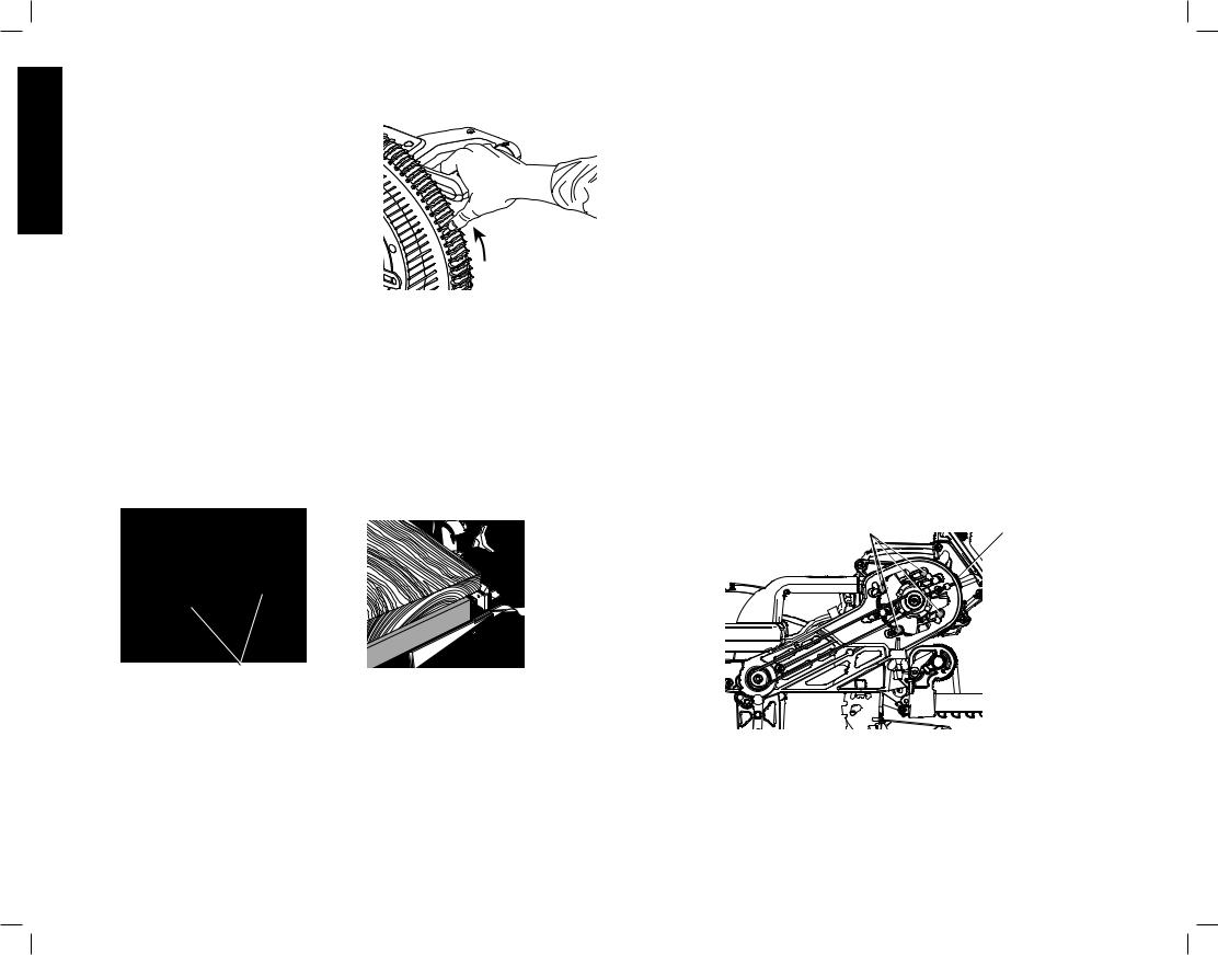
English
CUTTING LARGE MATERIAL (FIG. 32) |
|
Occasionally you will encounter a piece of wood a |
FIG. 32 |
little too large to fit beneath the lower guard. If this |
|
occurs, simply place your right thumb on the |
|
upper side of the guard and roll the guard up just |
|
enough to clear the workpiece, as shown in |
|
Figure 32. Avoid doing this as much as possible, |
|
but if need be, the saw will operate properly and |
|
make the bigger cut. NEVER TIE, TAPE, OR |
|
OTHERWISE HOLD THE GUARD OPEN WHEN |
|
OPERATING THIS SAW. |
|
SPECIAL SET-UP FOR WIDE CROSSCUTS (FIG. 33, 34)
Your saw can cut very wide (up to 16.1" [409 mm]) workpieces when a special set-up is used. To set the saw up for these workpieces, follow these steps:
1.Remove both left and right sliding fences from the saw and set aside. To remove them, unscrew the fence adjustment knobs several turns and slide each fence outward. Adjust and lock the miter control so that it is at 0º miter.
2.Make a platform using a piece of 1.5" (38 mm) thick particleboard or similar flat strong 1.5" thick wood to the dimensions: 14.5" x 26" (368 x 660 mm). The platform must be flat, otherwise the material could move during cutting and cause injury.
3.Mount the 14.5" x 26" (368 x 660 mm) platform to the saw using four 3" (76.2 mm) long wood screws through the holes in the base fence (Fig. 33). Four screws must be used to properly secure the material. When the special set-up is used, the platform will be cut into two pieces. Ensure the screws are tightened properly, otherwise material could loosen and cause injury. Ensure the platform is firmly flat on the table, against the fence, and centered evenly from left to right.
FIG. 33 |
FIG. 34 |
|
BASE
FENCE
SCREWS (two each side)
 WARNING: Ensure the saw is mounted firmly to a stable flat surface. Failure to do so could cause the saw to be unstable and fall causing personal injury.
4.Place the workpiece to be cut on top of the platform mounted to the table. Ensure the workpiece is firmly against the back of the base fence (Fig. 34).
5.Secure the material before cutting. Cut slowly through the material using a out-down-and- back motion. Failure to clamp securely or cut slowly could result in the material coming loose and causing injury.
After several cuts are made at various miter angles other than 0º, the platform may weaken and not properly support the work. Install a new, unused platform to the saw after presetting the desired miter angle.
 CAUTION: Continued use of a platform with several kerfs may cause loss of material control and possible injury.
MAINTENANCE
 WARNING: To reduce the risk of serious personal injury, turn tool off and remove the battery packs or power supply before transporting, making any adjustments, cleaning, repairing, or removing/installing attachments or accessories. An accidental start-up can cause injury.
 WARNING: To reduce the risk of serious personal injury, DO NOT touch the sharp points on the blade with fingers or hands while performing any maintenance.
DO NOT use lubricants or cleaners (particularly spray or aerosol) in the vicinity of the plastic guard. The polycarbonate material used in the guard is subject to attack by certain chemicals.
•All bearings are sealed. They are lubricated for life and need no further maintenance.
•Periodically clean all dust and wood chips from around AND UNDER the base and the rotary table. Even though slots are provided to allow debris to pass through, some dust will accumulate.
•The brushes are designed to give you several years of use. If they ever need replacement, return the tool to the nearest service center for repair.
Removing and Replacing Belt (Fig. 4, 35)
The belt is designed to last the life of the tool. However, abuse of the tool could cause the belt to fail.
If the blade does not turn when the motor is running, the belt has failed. To inspect or replace the belt, remove the belt cover screws. Remove the belt cover. Inspect the ribs of the belt for wear or failure. Check belt tension by squeezing the belt. The belt halves should almost touch when squeezing firmly with the thumb and index finger. To adjust the tension, loosen, but do not remove, the four crosshead screws (BJ). Then rotate the set screw (BK) on the top of the motor plate casting until the proper tension is achieved. Tighten the four screws securely and replace the belt cover.
NOTICE: Overtightening the belt will cause premature motor failure.
FIG. 35
BJ |
BK |
Cleaning
 WARNING: Blow dirt and dust out of all air vents and guard mechanisms (if applicable) with clean, dry air at least once a week. To minimize the risk of eye injury, always wear ANSI Z87.1 approved eye protection and respiratory protection when performing this.
 WARNING: Never use solvents or other harsh chemicals for cleaning the non-metallic parts of the tool. These chemicals may weaken the plastic materials used in these parts. Use a cloth dampened only with water and mild soap. Never let any liquid get inside the tool; never immerse any part of the tool into a liquid.
18
CLEANING THE DeWALT CORDED POWER SUPPLY
 WARNING: Never use solvents or other harsh chemicals for cleaning the non-metallic parts of the tool. These chemicals may weaken the plastic materials used in these parts. Use a cloth dampened only with water and mild soap. Never let any liquid get inside the tool; never immerse any part of the tool into a liquid.
CLEANING THE CORDED POWER SUPPLY RECEPTACLE
 WARNING: Blow debris out of the corded power supply receptacle (BF) with clean, dry air. To minimize the risk of eye injury, always wear ANSI Z87.1 approved eye protection and respiratory protection when performing this.
DUST DUCT CLEANING
Depending on your cutting environment, saw dust can clog the dust duct and may prevent dust from flowing away from the cutting area properly. With the battery pack or corded power supply removed and the saw head raised fully, low pressure air or a large diameter dowel rod can be used to clear the dust out of the dust duct.
CUTLINE™ LED WORKLIGHT CLEANING
For the best worklight performance, perform the following maintenance regularly with the battery or corded power supply removed.
•Carefully clean sawdust and debris from worklight lens with a cotton swab.
•DO NOT use solvents of any kind, they may damage the lens.
•Dust build-up can block the worklight and prevent it from accurately indicating the line of cut.
•Follow miter saw’s instruction manual to remove and install blade.
•With blade removed from saw, clean pitch and build-up from blade. Pitch and debris can interfere with the worklight and prevent it from accurately indicating the line of cut.
Accessories
 WARNING: Since accessories, other than those offered by DeWALT, have not been tested with this product, use of such accessories with this tool could be hazardous. To reduce the risk of injury, only DeWALT recommended accessories should be used with this product.
Recommended accessories for use with your tool are available at extra cost from your local dealer or authorized service center. If you need assistance in locating any accessory, please contact DeWALT Industrial Tool Co., 701 East Joppa Road, Towson, MD 21286, call 1-800-4-DeWALT (1-800-433-9258) or visit our website: www.dewalt.com.
OPTIONAL ACCESSORIES
The following accessories, designed for your saw, may be helpful. In some cases, other locally obtained work supports, length stops, clamps, etc., may be more appropriate. Use care in selecting and using accessories.
Extension |
Used to support long |
|
Work Support: |
overhanging work pieces, |
|
DW7080 |
the work support is |
|
|
user assembled. Your |
|
|
saw base is designed |
|
|
to accept two work |
|
|
supports, one on each |
LOCKNUTS |
|
side. |
|
|
|
|
|
|
END PLATE |
Adjustable Length |
Requires the use of one |
Stop: DW7051 |
Extension Work Support |
|
(DW7080). It is used to |
|
make repetitive cuts of |
|
the same length from 0 |
|
to 42" (107 cm). |
KNOBS 
 BRACKET
Clamp: DW7082 |
Used for firmly clamping |
(similar model |
workpiece to the saw |
included) |
table for precision cutting. |
Dust Bag: |
Equipped with a zipper |
DW7053 |
for easy emptying, the |
(included with |
dust bag will capture the |
some models) |
majority of the sawdust |
|
produced. |
|
|
Crown Molding |
Used for precision cutting |
Fence: DW7084 |
of crown molding. |
SAW BLADES: ALWAYS USE 12" (305 mm) SAW BLADES WITH EITHER 1" (25.4 mm) OR 5/8" (15.88 mm) ARBOR HOLES. SPEED RATING MUST BE AT LEAST 4800 RPM. Never use a smaller diameter blade. It will not be guarded properly. Use crosscut blades only! Do not use blades designed for ripping, combination blades or blades with hook angles in excess of 7°.
English
19

|
BLADE DESCRIPTIONS |
|
||
|
APPLICATION |
DIAMETER |
TEETH |
|
English |
Construction Saw Blades (thin kerf with anti-stick rim) |
|||
General Purpose |
12" (305 mm) |
40 |
||
|
||||
|
Fine Crosscuts |
12" (305 mm) |
60 |
|
|
Woodworking Saw Blades (provide smooth, clean cuts) |
|||
|
Fine crosscuts |
12" (305 mm) |
80 |
|
|
Non-ferrous metals |
12" (305 mm) |
96 |
|
NOTE: For cutting non-ferrous metals, use only saw blades with TCG (Triple Chip Grind) teeth designed for this purpose.
Repairs
The charger, power supply and battery pack are not serviceable. There are no serviceable parts inside the charger, power supply and battery pack.
 WARNING: To assure product SAFETY and RELIABILITY, repairs, maintenance and adjustment (including brush inspection and replacement) should be performed by a DeWALT factory service center or a DeWALT authorized service center. Always use identical replacement parts.
Service Information
Please have the following information available for all service calls:
Model Number __________________ Serial Number __________________________________
Date and Place of Purchase _______________________________________________________
Register Online
Thank you for your purchase. Register your product now for:
•WARRANTY SERVICE: Registering your product will help you obtain more efficient warranty service in case there is a problem with your product.
•CONFIRMATION OF OWNERSHIP: In case of an insurance loss, such as fire, flood or theft, your registration of ownership will serve as your proof of purchase.
•FOR YOUR SAFETY: Registering your product will allow us to contact you in the unlikely event a safety notification is required under the Federal Consumer Safety Act.
Register online at www.dewalt.com/register.
Three Year Limited Warranty
DeWALT will repair, without charge, any defects due to faulty materials or workmanship for three years from the date of purchase. This warranty does not cover part failure due to normal wear or tool abuse. For further detail of warranty coverage and warranty repair information, visit www.dewalt.com or call 1-800-4-DeWALT (1-800-433-9258). This warranty does not apply to accessories or damage caused where repairs have been made or attempted by others. This warranty gives you specific legal rights and you may have other rights which vary in certain states or provinces.
In addition to the warranty, DeWALT tools are covered by our:
1 YEAR FREE SERVICE
DeWALT will maintain the tool and replace worn parts caused by normal use, for free, any time during the first year after purchase.
2 YEARS FREE SERVICE ON DeWALT BATTERY PACKS
DC9071, DC9091, DC9096, DC9182, DC9280, DC9360,
DCB120, DCB127, DCB201, DCB203, DCB203BT, DCB207, DCB361
3 YEARS FREE SERVICE ON DeWALT BATTERY PACKS
DCB200, DCB204, DCB204BT, DCB205, DCB606
DeWALT BATTERY PACKS
Product warranty voided if the battery pack is tampered with in any way. DeWALT is not responsible for any injury caused by tampering and may prosecute warranty fraud to the fullest extent permitted by law.
90 DAY MONEY BACK GUARANTEE
If you are not completely satisfied with the performance of your DeWALT Power Tool, Laser, or Nailer for any reason, you can return it within 90 days from the date of purchase with a receipt for a full refund – no questions asked.
LATIN AMERICA: This warranty does not apply to products sold in Latin America. For products sold in Latin America, see country specific warranty information contained in the packaging, call the local company or see website for warranty information.
FREE WARNING LABEL REPLACEMENT: If your warning labels become illegible or are missing, call 1-800-4-DeWALT (1-800-433-9258) for a free replacement.
20

Troubleshooting Guide
BE SURE TO FOLLOW SAFETY RULES AND INSTRUCTIONS
TROUBLE! |
WHAT’S WRONG? |
WHAT TO DO |
||
Saw will not start |
1. Battery or power supply not installed |
1. |
Install battery or power supply. Refer to Installing and Removing the Battery Packs or |
|
|
|
|
|
Installing and Removing DeWALT Corded Power Supply. |
|
2. |
Battery or power supply not fully inserted |
2. |
Check that battery or power supply are fully latched. Check AC adapter plug in the motor housing |
|
|
|
|
for debris. Refer to DeWALT Corded Power Supply Cleaning Instructions. |
|
3. |
Batteries not charged |
3. |
Charge batteries. Refer to Charging Procedure. |
|
4. |
Power supply not plugged in |
4. |
Plug in saw. |
|
5. |
Cord damaged |
5. |
Have cord replaced by authorized service center. |
|
6. |
Fuse blown or breaker tripped |
6. |
Replace fuse or reset circuit breaker. |
|
7. |
Saw overheated |
7. |
Wait several minutes for saw to cool. |
|
8. |
Batteries overheated |
8. |
Wait several minutes for batteries to cool. |
Saw makes |
1. Dull blade |
1. |
Replace blade. Refer to Changing or Installing a New Saw Blade. |
|
unsatisfactory cuts |
2. Blade mounted backwards |
2. |
Turn blade around. Refer to Changing or Installing a New Saw Blade. |
|
|
3. |
Gum or pitch on blade |
3. |
Remove blade and clean with turpentine and coarse steel wool or household oven cleaner. |
|
4. |
Incorrect blade for work being done |
4. |
Change the blade type. Refer to Saw Blades under Accessories. |
Blade does not come up |
1. Extension cord too light or too long |
1. |
Replace with adequate size cord. Refer to Use Proper Extension Cord under Important Safety |
|
to speed |
|
|
|
Instructions. |
|
2. |
Low house current |
2. |
Contact your electric company. |
Machine vibrates excessively |
1. Saw not mounted securely to stand or |
1. |
Tighten all mounting hardware. Refer to Bench Mounting. |
|
|
|
work bench |
|
|
|
2. |
Stand or bench on uneven floor |
2. |
Reposition on flat level surface. Refer to Familiarization. |
|
3. |
Damaged saw blade |
3. |
Replace blade. Refer to Changing or Installing a New Saw Blade. |
Does not make accurate |
1. Miter scale not adjusted correctly |
1. |
Check and adjust. Refer to Miter Scale Adjustment under Adjustments. |
|
miter cuts |
2. Miter pointer not adjusted correctly |
2. |
Check and adjust. Refer to Miter Pointer Adjustment under Adjustments. |
|
|
3. |
Workpiece is not perpendicular to table |
3. |
Check and adjust fence. Refer to Fence Adjustment under Adjustments. |
|
4. |
Workpiece moving |
4. |
Clamp workpiece securely to fence or glue 120 grit sandpaper to fence with rubber cement. |
Material pinches blade |
1. Cutting bowed material |
1. |
Refer to Bowed Material under Special Cuts. |
|
CUTLINE™ worklight flashing |
1. Battery low on charge |
1. |
Charge batteries. Refer to Charging the Battery. |
|
|
2. |
Battery hot |
2. |
Wait several minutes for batteries to cool. |
English
21
 Loading...