


PORTUGUÊS |
ESPAÑOL |
FRANÇAIS |
ENGLISH |
AVR-E200
AV SURROUND RECEIVER
Getting Started
Mise en route / Antes de empezar / Iniciação
ENGLISH |
FRANÇAIS |
ESPAÑOL |
PORTUGUÊS |
ESPAÑOL |
NEDERLANDS |
SVENSKA |
Read before use
Thank you for purchasing this Denon product.
This Getting Started guide will let you quickly and easily setup this unit and connect it to your other devices.
Contents
Read before use ·····································································1
Accessories·····················································································1
About this manual·········································································1
Cautions on handling····································································1
Connecting the speakers····················································2
Before setting up the speakers·······································5
Set up speakers ·····································································6
Playing a Blu-ray Disc player··········································10
About this manual
nnOperation buttons
The operations described in this manual are based mainly on remote control operation.
nnSymbols
vThis symbol indicates a reference page on which related information is described.
mThis symbol indicates the page of the owner’s manual on the CD-ROM provided.
|
This symbol indicates a supplementary information |
|
|
and tips for operations. |
|
NOTE |
This symbol indicates points to remember operations |
|
or function limitations. |
||
|
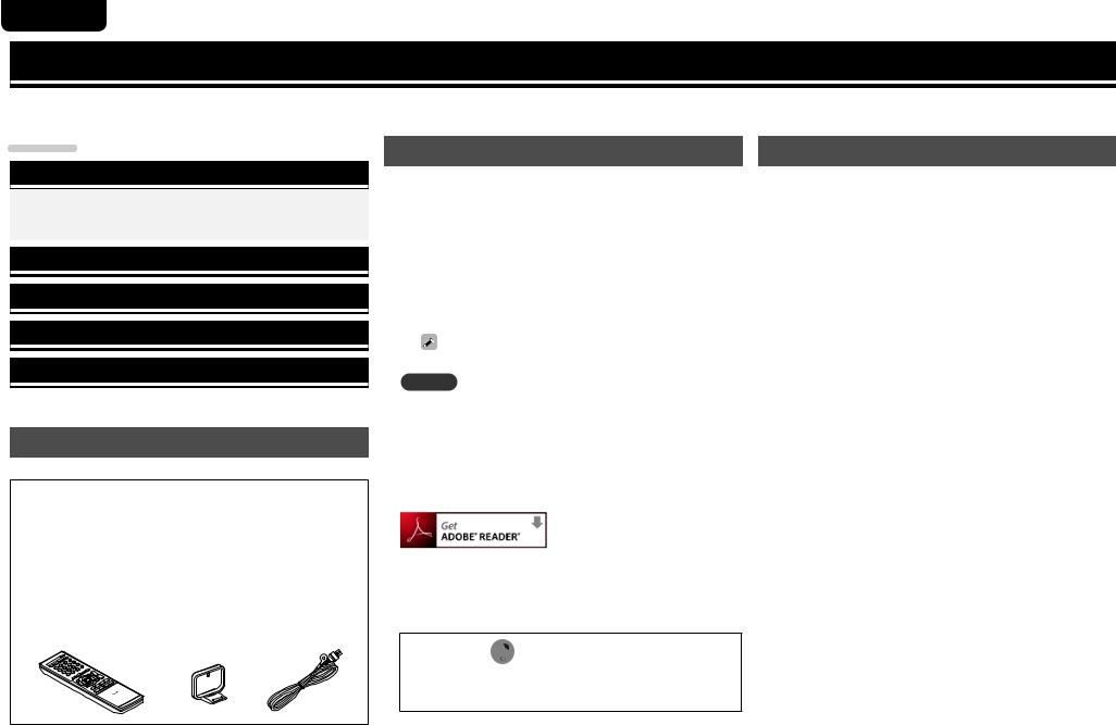
Accessories
Check that the following parts are supplied with the product.
q Getting Started......................................................................... |
|
1 |
w CD-ROM (Owner’s manual)..................................................... |
|
1 |
e Safety Instructions................................................................... |
|
1 |
r Warranty (for North America model only) |
................................ 1 |
|
t Remote control unit (RC-1180)................................................ |
|
1 |
y R03/AAA batteries................................................................... |
|
2 |
u AM loop antenna...................................................................... |
|
1 |
i FM indoor antenna................................................................... |
|
1 |
o Speaker cable label.................................................................. |
|
1 |
t |
u |
i |
nnIllustrations
Note that the illustrations in this manual are for explanation purposes and may differ from the actual unit.
nnAbout the CD-ROM
(Getting Started / Owner’s manual)
You need to have Adobe Reader® installed on your computer to view the owner’s manuals on the CD-ROM.
Click the Adobe Reader® banner in the CD-ROM menu to install the Adobe Reader® (for Windows).
If you click the  mark on the front cover of the supplied owner’s manuals on the CD-ROM, the mark operation explanation screen list is displayed. Check this list before viewing the owner’s manuals on the CD-ROM.
Cautions on handling
•Before turning the power switch on
Check once again that all connections are correct and that there are no problems with the connection cables.
•Power is supplied to some of the circuitry even when the unit is set to the standby mode. When going on vacation or leaving home for long periods of time, be sure to unplug the power cord from the power outlet.
•About Condensation
If there is a major difference in temperature between the inside of the unit and the surroundings, condensation (dew) may form on the operating parts inside the unit, causing the unit not to operate properly.
If this happens, let the unit sit for an hour or two with the power turned off and wait until there is little difference in temperature before using the unit.
•Cautions on using mobile phones
Using a mobile phone near this unit may result in noise. If that occurs, move the mobile phone away from this unit when it is in use.
•Moving the unit
Turn off the power and unplug the power cord from the power outlet. Next, disconnect the connection cables to other system units before moving the unit.
•About Care
•Wipe the cabinet and control panel clean with a soft cloth.
•Follow the instructions when using a chemical cleaner.
•Benzene, paint thinner or other organic solvents as well as insecticide may cause material changes and discoloration if brought into contact with the unit, and should therefore not be used.
1

SVENSKA |
NEDERLANDS |
ESPAÑOL |
PORTUGUÊS |
ESPAÑOL |
FRANÇAIS |
ENGLISH |
Connecting the speakers
This unit can perform 2.0-channel (two speaker stereo), 2.1-channel (two speakers and a subwoofer) and 5.1-channel (five speakers and a subwoofer) playback. Here, we explain the installation and connection procedure when using 5.1-channel speakers.
For the installation procedure when using other than 5.1-channel, see vm page 23 “Installation/connection/setup of speakers (Advanced)”. nnDo not plug the power plug of the main unit into the wall socket until these preparations are complete.
nnFor operation of the connected devices, refer to the user manuals for each device.
What you need for this step |
Install |
|
|
Speaker |
Subwoofer |
TV |
|||||
|
|
(with built-in amplifier) |
(with HDMI input) |
||||||
(sold separately) |
|||||||||
(sold separately) |
(sold separately) |
||||||||
|
|
|
|
|
|
|
|||
|
|
|
|
|
|
|
|
|
|
|
|
|
|
|
|
|
|
|
|
FL |
FR |
SL |
SR |
|
|
|
|
||
|
C |
|
|
|
|
Speaker cable |
Subwoofer cable |
HDMI cable |
|
|
(sold separately) |
(sold separately) |
(sold separately) |
|
•Prepare enough for the |
|
|
number of speakers you will |
|
|
use. |
|
|
Speaker cable label |
Remote control unit |
R03/AAA batteries |
(supplied) |
(supplied) |
(supplied) |
nnTypical 5.1-channel surround sound speakers layout
FL |
FR |
|
SW |
|
C |
|
z1 |
|
z2 |
SL |
SR |
Listening position
z1 22˚ – 30˚
FL Front speaker (L) FR Front speaker (R) C Center speaker SW Subwoofer
SL Surround speaker (L) SR Surround speaker (R)
z2 120˚
•Use the illustration below as a guide for how high each speaker should be installed. The height does not need to be exactly the same.
|
|
|
Surround |
|
|
||
|
Front |
speaker |
|
|
|||
|
|
|
|
|
|
||
|
speaker |
2 – 3 ft / |
|
|
|
||
|
|
|
|
||||
|
|
|
60 – 90 cm |
|
|
||
|
|
|
|
|
|
|
|
|
|
|
|
|
|
|
|
|
|
|
|
|
|
|
|
GViewed from the sideH
Connect
Preparation
Setup
Playback
2

ENGLISH |
FRANÇAIS |
ESPAÑOL |
PORTUGUÊS |
ESPAÑOL |
NEDERLANDS |
SVENSKA |
Preparation
Carefully check the left (L) and right (R) channels and + (red) and – (black) polarities on the speakers being connected to the this unit, and be sure to connect the channels
and polarities correctly. nnConnecting the speaker cable
1 Peel off about 3/8 inch/10 mm of sheathing from the tip of the speaker cable, then either twist the core wire tightly or terminate it.
2 Press the lever on the speaker terminal.
3 Holding the lever on the speaker terminal, insert the core wire of the speaker cable all the way into the speaker terminal.
4 Release your finger from the lever on the speaker terminal.
NOTE
•Disconnect this unit’s power plug from the power outlet before connecting the speakers. Also, turn off the subwoofer.
•Connect so that the speaker cable core wires do not protrude from the speaker terminal. The protection circuit may be activated if the core wires touch the rear panel or if the + and – sides touch each other (vm page 54 “Protection circuit”).
•Never touch the speaker terminals while the power supply is connected. Doing so could result in electric shock.
•Use speakers with the speaker impedances shown below.
Speaker terminals |
Speaker |
|
impedance |
||
|
||
FRONT |
|
|
CENTER |
6 – 16 Ω/ohms |
|
SURROUND |
|
nnAbout the speaker cable label (supplied) for channel identification
The channel display section for speaker terminals on the rear panel is color-coded for each channel to be identifiable.
Speaker terminals |
Color |
FRONT L |
White |
FRONT R |
Red |
CENTER |
Green |
SURROUND L |
Light blue |
SURROUND R |
Blue |
Attach the speaker cable label for each channel to its speaker cable as shown in the diagram.
Then, make the connection so that the color of the speaker terminal matches that of the speaker cable label.
GHow to attach the speaker cable labelH
Speaker |
|
|
|
This unit |
|
|||||
|
|
|
|
|
|
|
|
|
|
|
|
|
|
|
|
|
|
|
|
|
|
|
|
|
|
|
|
|
|
|
|
|
|
|
|
|
|
|
|
|
|
|
|
|
|
|
|
|
|
|
|
|
|
|
|
|
|
|
|
|
|
|
|
|
|
|
|
|
|
|
|
|
|
|
|
|
|
|
|
|
|
|
|
|
|
|
|
|
|
|
|
|
|
|
|
|
|
|
|
|
|
|
|
|
|
|
|
|
|
|
|
|
|
|
|
|
|
|
|
|
|
|
|
|
|
|
|
|
|
|
|
|
|
|
|
|
|
|
|
|
|
|
|
|
|
|
|
|
|
|
|
|
|
|
|
|
|
|
|
|
|
|
|
|
|
|
|
|
|
|
|
|
|
|
|
3
 Loading...