


Operating Instructions
1500 WATT POWER INVERTER
CPI |
|
1500 |
Part No. 480-059-P |
|
|||
|
|||
|
|
|
Printed in China |
|
|
|
|
Nothing Comes Close To A Cobra™ |
English |
||
|
|
|
|
 Our Thanks To You
Introduction
Thank you for purchasing the Cobra® CPI 1500 inverter. Properly used, this Cobra® product will give you many years of reliable service.
How Your Cobra® Power Inverter Works
The Cobra® Power Inverter is an electronic product that has been designed and built to take low voltage DC (Direct Current) power from your automobile or other low voltage power supplies and CONVERT it to standard 115 volt AC (Alternating Current) power like the current you have in your home. This conversion process thereby allows you to use many of your household appliances and electronic products in automobiles, RVs, boats, tractors, trucks and virtually anywhere else.
Customer Assistance
Customer Assistance
Should you encounter any problems with this product, or not understand its many features, please refer to this owner’s manual. If you require further assistance after reading this manual, Cobra® Electronics offers the following customer assistance services:
For Assistance In the U.S.A.
Automated Help Desk English only.
24 hours a day, 7 days a week 773-889-3087 (phone).
Customer Assistance Operators English and Spanish. 8:00 a.m. to 6:00 p.m. CT, Monday through Friday (except holidays) 773-889-3087 (phone).
Questions English and Spanish.
Faxes can be received at 773-622-2269 (fax).
Technical Assistance English only.
www.cobra.com (on-line: Frequently Asked Questions). English and Spanish. productinfo@cobra.com (e-mail).
For Assistance Outside the U.S.A.
Contact Your Local Dealer
|
©2003 Cobra® Electronics Corporation |
|
6500 West Cortland Street |
A1 English |
Chicago, Illinois 60707 USA |
www.cobra.com |
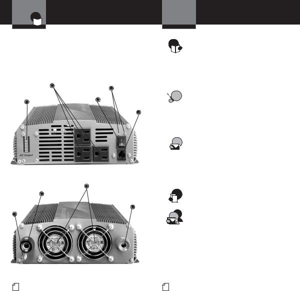
Controls /Indicators
 and Product Features
Introduction
Features
• Three AC Receptacles |
• Reverse Polarity |
|
|
• Current Meter |
Protection |
|
|
• Remote On/Off Capable |
• Low Battery Alarm |
|
|
• Automatic Thermal |
• Low Battery Shutdown |
|
|
Protection/Shutdown |
|
|
|
AC Outlets |
Power & Protection |
|
|
Indicators |
|
||
|
|
|
|
Current |
|
On/Off Power |
Remote |
|
Switch |
||
Meter |
|
|
On/Off |
Switch
Jack
Negative Battery
Cooling Fans
Cable Terminal (Black)
Positive Battery
Cable Terminal
(Red)
Ground
Terminal
 Table of Contents
Introduction
Introduction
Our Thanks to You . . . . . . . . . . . . . . . . . . A1 Customer Assistance . . . . . . . . . . . . . . . . A1 Controls and Indicators . . . . . . . . . . . . . . A2 Product Features . . . . . . . . . . . . . . . . . . . A2 Important Safety Information . . . . . . . . . . . 1 Quick Evaluation Before Installation . . . . . . .4
Installation
Installation Requirements . . . . . . . . . . . . . . 6
Mounting . . . . . . . . . . . . . . . . . . . . . . . . . . 7
Connecting Cables . . . . . . . . . . . . . . . . . . . 8
Power Consumption . . . . . . . . . . . . . . . . . 12
Ground Wiring . . . . . . . . . . . . . . . . . . . . . 13
Operation
Turning Your Inverter On or Off . . . . . . . . 14 Remote On/Off Switch . . . . . . . . . . . . . . . 15 Power and Protection Indicators . . . . . . . 16 Operating Limits . . . . . . . . . . . . . . . . . . . . 17 Troubleshooting Guide . . . . . . . . . . . . . . . 18 Specifications . . . . . . . . . . . . . . . . . . . . . . 19
Warranty
Warranty . . . . . . . . . . . . . . . . . . . . . . . . . . 20
Customer Assistance
Maintenance . . . . . . . . . . . . . . . . . . . . . . . .21
Product Service . . . . . . . . . . . . . . . . . . . . 21
Accessories and Order Form . . . . . . . . . . 22
A2 English |
A3 English |
Important Safety
 Information
Introduction
Important Safety Information
•
Before installing and using your Cobra® Power Inverter, please read these general precautions and warnings.
Caution and Warning Statements
To make the most of this inverter, it must be installed and used properly. Please read the installation and operating instructions carefully before installing and using it. Special attention must be paid to the CAUTION and WARNING statements in the manual.
CAUTION Statements specify conditions which could cause damage to the unit or other equipment.
WARNING Statements identify conditions that could result in personal injury or loss of life.
General Precautions
1.Never install the inverter in a boat’s engine compartment where gas and battery fumes are present.
2.Do not operate the inverter if it has been dropped or damaged in any way.
3.Do not open the inverter; it contains no userserviceable parts. Attempting to service unit could cause electrical shock.
NOTE Internal components remain charged after all power is disconnected.
4.Do not expose the inverter to rain, snow, bilge water or spray.
5.Do not obstruct the ventilation openings.
6.Do not install the inverter in zero-clearance compartment.
CAUTION This inverter should be used in negative ground applications only.
Continued…
Nothing comes close to a Cobra™ 1
Important Safety
 Information
inverters contain components arcs or sparks. To prevent
do not install the inverter in containing batteries or
or in locations that require equipment.
the risk of fire, do not cover ventilation openings. Do not install -clearance compartment.
Appliances
nickel cadmium batteries to the Cobra® 1500W
types of equipment are
Dangerous Voltages 2. Certain battery chargers for battery packs used in hand
power tools. These chargers have a WARNING label stating that dangerous voltages are present at the battery terminals.
This problem does not occur with the vast majority of battery operated equipment. Most use a separate charger or transformer that is plugged into the AC receptacle and produces a low voltage output. If the label on the AC adapter or charger states that it produces a low voltage AC or DC output (less than 30 volts), the inverter will have no problem powering the adapter safely.
Important Safety
 Information
Introduction
Cobra® 1500W Output Waveform
Some very sensitive electronic equipment may not operate satisfactory on “square wave” or “modified sine wave.” The output waveform is referred to as “square wave” or “modified sine wave.” It is a stepped waveform designed to have characteristics similar
to the sine wave shape of utility power. A waveform of this nature is suitable for most AC loads (including
linear and switching power suppliers used in electronic equipment, transformers and motors).
2 English |
Nothing comes close to a Cobra™ 3 |
A 12 volt
Power Supply
10 to get the current (in amperes) the power source must deliver.
power source to the inverter
as short and thick as possible in voltage drop between the power when it is drawing current
.
excessive voltage drop, the inverter drawing higher currents because
dropped below 10 volts.
cable is recommended. than 1.5 meters (4 ft.).
that connects to the inverter must stripped off for about 1⁄2 inch (1.25 end, exposing the bare copper.
cable, which connects to the power with a lug or other connector
low resistance connection.
power source is a battery, the cable must be terminated with a battery terminal that clamps to the post on the battery.
Quick Evaluation
 Before Installation
Introduction
A test load that can be plugged into the AC receptacle on the inverter for short term testing at a low power level. The following cables are recommended for testing low power level test loads only.
|
Test Load |
Minimum |
|
||
|
Power |
Cable Size |
|
|
AWG copper |
|
|
AWG copper |
|
|
AWG copper |
|
|
Installation:
1.Turn the inverter Off (see page 14 for details). If the power source is
a DC power supply, switch it Off as well.
2.Connect cables to Power Input Terminals (see page 8 for details).
3.Connect cables to power source (see page 8 for details).
4.Check to make sure all connections are secure.
5.Turn the inverter On. If the power source is a DC power supply, switch it On first.
6. Plug in the test load.
The inverter should supply power to the load. If the inverter is not working properly, refer to the Troubleshooting Guide on page 18
Connect Test Load
or Power and Protection Indicators section on page 16.
4 English |
Nothing comes close to a Cobra™ 5 |
 Loading...