


 Loading...
Cisco Catalyst 9200 Series Switches Hardware Installation Guide
First Published: 2018-11-19
Last Modified: 2019-02-06
Americas Headquarters
Cisco Systems, Inc. 170 West Tasman Drive
San Jose, CA 95134-1706 USA http://www.cisco.com Tel: 408 526-4000
800 553-NETS (6387) Fax: 408 527-0883
© 2018–2019 Cisco Systems, Inc. All rights reserved.

C H A P T E R 1
C H A P T E R 2
C O N T E N T S
Product Overview |
|
1 |
|
|
|
|
Switch Models |
1 |
|
|
|
|
|
Front Panel Components |
2 |
|
||||
10/100/1000 Ports |
3 |
|
|
|
||
PoE and PoE+ Ports |
4 |
|
|
|||
Management Ports |
4 |
|
|
|||
USB Type A Port |
5 |
|
|
|
||
Uplink Ports |
5 |
|
|
|
|
|
Rear Panel |
6 |
|
|
|
|
|
RFID Tag |
8 |
|
|
|
|
|
StackWise Ports |
8 |
|
|
|
||
Power Supply Modules |
8 |
|
||||
Fan Modules |
9 |
|
|
|
|
|
Ethernet Management Port |
10 |
|||||
RJ-45 Console Port |
10 |
|
||||
Network Configurations |
|
11 |
|
|||
Installing the Switch |
13 |
|
|
|
|
|
Preparing for Installation |
13 |
|
||||
Safety Warnings |
13 |
|
|
|
||
Installation Guidelines |
15 |
|
||||
Shipping Box Contents |
15 |
|
||||
Tools and Equipment |
|
16 |
|
|||
Verifying Switch Operation |
17 |
|||||
Planning a Switch Data Stack |
17 |
|||||
Switch Stacking Guidelines |
17 |
|||||
Cisco Catalyst 9200 Series Switches Hardware Installation Guide
iii

Contents
|
|
Data Stack Cabling Configurations |
17 |
|
|
|||||
|
|
Data Stack Bandwidth and Partitioning Examples |
18 |
|||||||
|
|
Power-On Sequence for Switch Stacks |
20 |
|
||||||
|
|
Installing the Switch |
21 |
|
|
|
|
|
|
|
|
|
Rack-Mounting |
21 |
|
|
|
|
|
|
|
|
|
Attaching the Rack-Mount Brackets |
22 |
|
|
|||||
|
|
Mounting the Switch a Rack |
24 |
|
|
|
||||
|
|
Installing the Switch on a Table or Shelf |
24 |
|
||||||
|
|
After Switch Installation |
25 |
|
|
|
|
|
||
|
|
Connecting to the StackWise Ports |
25 |
|
|
|
||||
|
|
Connecting Devices to the Ethernet Ports |
27 |
|
||||||
|
|
10/100/1000 Port Connections |
27 |
|
|
|
||||
|
|
Auto-MDIX Connections |
27 |
|
|
|
|
|||
|
|
Auto-MDIX Connections |
27 |
|
|
|
|
|||
|
|
PoE and POE+ Port Connections |
28 |
|
|
|
||||
C H A P T E R |
3 |
Installing a Network Module |
31 |
|
|
|
|
|
|
|
|
|
Installing a Network Module in the Switch |
31 |
|
||||||
|
|
Safety Warnings |
31 |
|
|
|
|
|
|
|
|
|
Equipment That You Need |
31 |
|
|
|
|
|||
|
|
Installing a Network Module |
32 |
|
|
|
||||
|
|
Removing a Network Module |
34 |
|
|
|
|
|||
|
|
Finding the Network Module Serial Number 34 |
|
|||||||
|
|
Installing and Removing SFP Modules |
35 |
|
|
|||||
|
|
Installing SFP/SFP+ Modules 35 |
|
|
|
|||||
|
|
Removing SFP/SFP+ Modules |
37 |
|
|
|
||||
C H A P T E R |
4 |
Installing a Power Supply Unit |
39 |
|
|
|
|
|
||
|
|
Power Supply Modules Overview |
39 |
|
|
|
||||
|
|
Finding the Power Supply Module Serial Number 41 |
|
|||||||
|
|
Installation Guidelines |
42 |
|
|
|
|
|
|
|
|
|
Installing or Replacing an AC Power Supply Module |
43 |
|||||||
C H A P T E R |
5 |
Installing a Fan Module |
47 |
|
|
|
|
|
|
|
Cisco Catalyst 9200 Series Switches Hardware Installation Guide
iv

C H A P T E R 6
A P P E N D I X A
Contents
Fan Modules Overview |
47 |
|
|
|
|
|
|
|
|
Installation Guidelines |
48 |
|
|
|
|
|
|
|
|
Installing a Fan Module |
48 |
|
|
|
|
|
|
|
|
Finding the Fan Module Serial Number |
49 |
|
|
|
|
||||
Configuring the Switch |
51 |
|
|
|
|
|
|
|
|
Configuring the Switch Using the Web User Interface |
51 |
|
|
||||||
Setting up the Switch |
51 |
|
|
|
|
|
|
|
|
Connecting to the Switch |
51 |
|
|
|
|
|
|
||
Creating User Accounts |
52 |
|
|
|
|
|
|
||
Choosing Setup Options |
53 |
|
|
|
|
|
|
||
Configuring Basic Device Settings |
53 |
|
|
|
|
||||
Configuring Your Device Based on a Site Profile |
54 |
|
|
||||||
Configuring Switch Wide Settings |
59 |
|
|
|
|
||||
Configuring VLAN Settings 59 |
|
|
|
|
|
|
|||
Configure STP Settings |
60 |
|
|
|
|
|
|
||
Configuring DHCP, NTP, DNS and SNMP Settings |
60 |
|
|||||||
Configuring Port Settings |
61 |
|
|
|
|
|
|
||
Configuring the Switch Using the CLI |
|
62 |
|
|
|
|
|||
Accessing the CLI Through the Console Port |
62 |
|
|
|
|||||
Connecting the RJ-45 Console Port |
63 |
|
|
|
|
||||
Connecting the USB Console Port |
|
63 |
|
|
|
|
|||
Installing the Cisco Microsoft Windows USB Device Driver |
64 |
||||||||
Installing the Cisco Microsoft Windows XP USB Driver |
64 |
||||||||
Installing the Cisco Microsoft Windows 2000 USB Driver |
65 |
||||||||
Installing the Cisco Microsoft Windows Vista and Windows 7 USB Driver 65 |
|||||||||
Uninstalling the Cisco Microsoft Windows USB Driver |
65 |
|
|||||||
Uninstalling the Cisco Microsoft Windows XP and 2000 USB Driver 65 |
|||||||||
Uninstalling the Cisco Microsoft Windows Vista and Windows 7 USB Driver 66 |
|||||||||
Technical Specifications |
69 |
|
|
|
|
|
|
|
|
Environmental and Physical Specifications 69 |
|
|
|
|
|||||
Specifications for the Power Supplies and Fans |
72 |
|
|
|
|||||
Cisco Catalyst 9200 Series Switches Hardware Installation Guide
v

Contents
A P P E N D I X B
Switch LEDs 75
LEDs 75 |
|
|
Console LED |
75 |
|
System LED |
76 |
|
MASTER LED 76 |
||
STACK LED |
77 |
|
PoE LED |
78 |
|
Port LEDs and Modes 78 |
||
Beacon LED |
80 |
|
RJ-45 Console Port LED 81 |
||
Fan LED |
81 |
|
Uplink Port LEDs 81 |
||
Introduction |
? |
|
Cisco Catalyst 9200 Series Switches Hardware Installation Guide
vi

C H A P T E R 1
Product Overview
•Switch Models, on page 1
•Front Panel Components, on page 2
•Rear Panel, on page 6
•Network Configurations, on page 11
Switch Models
TheCiscoCatalyst9200Seriesswitcheshavefourmodular(C9200)andeightfixed(C9200L)switchmodels.
ThefollowingtablesdescribealltheavailableCiscoCatalyst9200Seriesswitchesandthefeaturessupported.
Table 1: C9200L Switch Models and Descriptions |
|
Switch Model |
Description |
C9200L-24P-4G |
Stackable 24x1G PoE+ ports; 4x1G fixed uplink ports; 2 power |
|
supply slots; 2 fixed fans; supports StackWise-80. |
C9200L-24P-4X |
Stackable 24x1G PoE+ ports; 4x10G fixed uplink ports; 2 power |
|
supply slots; 2 fixed fans; supports StackWise-80. |
C9200L-24T-4G |
Stackable 24x1G ports; 4x1G fixed uplink ports; 2 power supply |
|
slots; 2 fixed fans; supports StackWise-80. |
C9200L-24T-4X |
Stackable 24x1G ports; 4x10G fixed uplink ports; 2 power supply |
|
slots; 2 fixed fans; supports StackWise-80. |
C9200L-48P-4G |
Stackable 48x1G PoE+ ports; 4x1G fixed uplink ports; 2 power |
|
supply slots; 2 fixed fans; supports StackWise-80. |
C9200L-48P-4X |
Stackable 48x1G PoE+ ports; 4x10G fixed uplink ports; 2 power |
|
supply slots; 2 fixed fans; supports StackWise-80. |
C9200L-48T-4G |
Stackable 48x1G ports; 4x1G fixed uplink ports; 2 power supply |
|
slots; 2 fixed fans; supports StackWise-80. |
C9200L-48T-4X |
Stackable 48x1G PoE+ ports; 4x10G fixed uplink ports; 2 power |
|
supply slots; 2 fixed fans; supports StackWise-80. |
Cisco Catalyst 9200 Series Switches Hardware Installation Guide
1

Product Overview
Front Panel Components
Table 2: C9200 Switch Models and Descriptions |
|
Switch Model |
Description |
C9200-24P |
Stackable 24x1G PoE+ ports; 4x1G and 4x10G fixed uplink ports; |
|
2 power supply slots; 2 field-replaceable fans; supports |
|
StackWise-160. |
C9200-24T |
Stackable24x1Gports;4x1Gand4x10Gfixeduplinkports;2power |
|
supply slots; 2 field-replaceable fans; supports StackWise-160. |
C9200-48P |
Stackable 48x1G PoE+ ports; 4x1G and 4x10G fixed uplink ports; |
|
2 power supply slots; 2 field-replaceable fans; supports |
|
StackWise-160. |
C9200-48T |
Stackable48x1Gports;4x1Gand4x10Gfixeduplinkports;2power |
|
supply slots; 2 field-replaceable fans; supports StackWise-160. |
Front Panel Components
This section describes the front panel components of Cisco Catalyst 9200 Series switches :
•24 or 48 downlink ports of one of the following types:
•10/100/1000
•10/100/1000 PoE+
•1G/10G Uplink ports
•USB Type A storage ports
•USB mini-Type B console port
•LEDs
•Blue Beacon
All the switch models have similar components. See the following illustration for example.
Note The Cisco Catalyst 9200 Series switches might have slight cosmetic differences on the bezels.
Cisco Catalyst 9200 Series Switches Hardware Installation Guide
2
Product Overview
10/100/1000 Ports
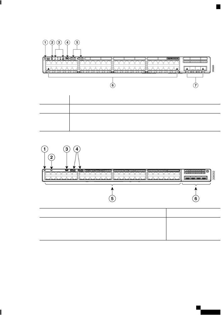
Figure 1: Front Panel of a C9200L Switch
1 |
Blue Beacon (UID button) |
5 |
USB Type A storage ports |
2 |
Mode button |
6 |
10/100/1000 PoE+ ports |
3 |
Status LEDs |
7 |
Fixed uplink ports |
4USB mini-Type B (console) port
Figure 2: Front Panel of a C9200 Switch
1 |
Blue Beacon (UID button) |
4 |
USB Type A storage ports |
2 |
Mode button |
5 |
10/100/1000 PoE+ ports |
3 |
USB mini-Type B (console) |
6 |
Network Module with uplink |
|
port |
|
ports |
10/100/1000 Ports
The 10/100/1000 ports use RJ-45 connectors with Ethernet pinouts. The maximum cable length is 328 feet (100 meters). The 100BASE-TX and 1000BASE-T traffic requires twisted pair (UTP) cable of Category 5 or higher. The 10BASE-T traffic can use Category 3 cable or higher.
Cisco Catalyst 9200 Series Switches Hardware Installation Guide
3

Product Overview
PoE and PoE+ Ports
PoE and PoE+ Ports
The PoE and PoE+ ports provide the following functionality:
•PoE/PoE+ ports: Support for IEEE 802.3af-compliant powered devices (up to 15.4W PoE per port) and support for IEEE 802.3at-compliant powered devices (up to 30W PoE+ per port).
•Support for pre-standard Cisco powered devices.
•Configurable support for Cisco intelligent power management, including enhanced power negotiation, power reservation, and per-port power policing.
See the Power Supply Modules, on page 8 for the power supply matrix that defines the available PoE and PoE+ power per port. The output of the PoE+ circuit has been evaluated as a Limited Power Source (LPS) per IEC 60950-1.
Management Ports
The management ports connect the switch to a PC running Microsoft Windows or to a terminal server.
•Ethernet management port. See Ethernet Management Port, on page 10.
•RJ-45 console port (EIA/TIA-232). See RJ-45 Console Port, on page 10.
•USB mini-Type B console port (5-pin connector).
The 10/100/1000 Ethernet management port connection uses a standard RJ-45 crossover or straight-through cable. The RJ-45 console port connection uses the supplied RJ-45-to-DB-9 female cable. The USB console port connection uses a USB Type A to 5-pin mini-Type B cable. The USB console interface speeds are the same as the RJ-45 console interface speeds.
If you use the USB mini-Type B console port, the Cisco Windows USB device driver must be installed on any PC connected to the console port (for operation with Microsoft Windows). Mac OS X or Linux do not require special drivers.
The 4-pin mini-Type B connector resembles the 5-pin mini-Type B connectors. They are not compatible. Use only the 5-pin mini-Type B.
Figure 3: USB Mini-Type B Port
This illustration shows a 5-pin mini-Type B USB port.
With the Cisco Windows USB device driver, you can connect and disconnect the USB cable from the console port without affecting Windows HyperTerminal operations.
The console output always goes to both the RJ-45 and the USB console connectors, but the console input is active on only one of the console connectors at any one time. The USB console takes precedence over the RJ-45console. WhenacableisconnectedintotheUSBconsoleport,theRJ-45consoleportbecomesinactive. Conversely, when the USB cable is disconnected from the USB console port, the RJ-45 port becomes active.
You can use the command-line interface (CLI) to configure an inactivity timeout which reactivates the RJ-45 console if the USB console has been activated and no input activity has occurred on the USB console for a specified time.
Cisco Catalyst 9200 Series Switches Hardware Installation Guide
4
Product Overview
USB Type A Port
After the USB console deactivates due to inactivity, you cannot use the CLI to reactivate it. Disconnect and reconnect the USB cable to reactivate the USB console. For information on using the CLI to configure the USB console interface, see the Software Configuration Guide.
USB Type A Port
The USB Type A port provides access to external USB flash devices (also known as thumb drives or USB keys).
The port supports Cisco USB flash drives with capacities from 128 MB to 8 GB. USB devices with port densities of 128 MB, 256 MB, 1 GB, 4 GB, and 8 GB are supported. When combined with stacking, you can upgrade other switches in the stack from an USB key inserted in any switch within the stack. Cisco IOS software provides standard file system access to the flash device: read, write, erase, and copy, as well as the ability to format the flash device with a FAT file system.
It provides you with the ability to automatically upgrade the internal flash with the USB drive's configuration and image for emergency switch recovery using USB auto-upgrade. This feature checks the internal flash for a bootable image and configuration and if either image or the configuration is not available, then the USB drive is checked for boot images and configuration. If the boot image and configuration are available, these are copied to flash for the reboot.
Uplink Ports
The Cisco Catalyst 9200 Series switches support both fixed uplinks and modular uplinks. The C9200 switch modelssupportmodularuplinkswithonehot-swappablenetworkmodulethatprovidesuplinkportstoconnect to other devices.
The fixed uplink ports on the C9200L switch models support two types of SFP/SFP+ modules.
•4x1G ports that support 1G SFP modules.
•4x10G ports that supports either 1G SFP or 10G SFP+.
For supported SFP/SFP+ modules, refer to the Cisco Transceiver Modules Compatibility Information at http://www.cisco.com/en/US/products/hw/modules/ps5455/products_device_support_tables_list.html
Note For information about installing an (uplink) SFP/SFP+ module, see Installing SFP/SFP+ Modules, on page 35.
Cisco Catalyst 9200 Series Switches Hardware Installation Guide
5

Product Overview
Rear Panel
Figure 4: Network Module C9200-NM-4G
1 LEDs |
2 Module slots |
The following table lists the optional Cisco Catalyst 9200 Series Switches uplink network modules with 1-Gigabit and 10-Gigabit slots.
Table 3: Supported Network Modules |
|
Network Module |
Description |
C9200-NM-4G |
This module has four 1G SFP module slots. Any combination of standard |
|
SFP modules are supported. SFP+ modules are not supported. |
|
If you insert an SFP+ module in the 1G network module, the SFP+ module |
|
does not operate, and the switch logs an error message. |
C9200-NM-4X |
This module has four 10G SFP module slots. Each port supports a 1G or 10G |
|
connection. Any combination of standard SFP modules are supported. |
C9200-NM-BLANK |
Insert this blank module when the switch has no uplink ports (this is required |
|
for sufficient air flow). |
Note For information about installing a network module, see Installing a Network Module, on page 32.
Rear Panel
The switch rear panel includes StackWise connectors, fan modules, and power supply modules.
Cisco Catalyst 9200 Series Switches Hardware Installation Guide
6

Product Overview
Rear Panel
Figure 5: Rear Panel of a C9200L Switch
1 |
RJ-45 console port |
4 |
Blue Beacon LED |
2 |
Fixed fan modules on |
5 |
MGMT (RJ-45 |
|
C9200L switches |
|
10/100/1000management |
|
|
|
port) |
3 |
Power supply module |
6 |
StackWise-80 port |
|
slots |
|
connectors |
Figure 6: Rear Panel of a C9200 Switch
1 |
RJ-45 console port |
4 |
Blue Beacon LED |
2 |
Modular fan modules on |
5 |
MGMT (RJ-45 |
|
C9200 switches |
|
10/100/1000management |
|
|
|
port) |
3 |
Power supply module |
6 |
StackWise-160 port |
|
slots |
|
connector slots with stack |
|
|
|
blanks installed |
Cisco Catalyst 9200 Series Switches Hardware Installation Guide
7

Product Overview
RFID Tag
RFID Tag
The switch has a built-in, front-facing, passive RFID tag that uses UHF RFID technology and requires an RFID reader with compatible software. It provides auto-identification capabilities for asset management and tracking. TheRFIDtagsarecompatiblewiththeGeneration2GS1EPCGlobalStandardandareISO18000-6C compliant. They operate in the 860to 960-MHz UHF band. For more information, see Radio Frequency Identification (RFID) on Cisco Catalyst 9000 Family Switches White Paper.
StackWise Ports
StackWise ports are used to connect switches in StackWise stacking configurations. The switch ships with a 0.5-meterStackWisecablethatyoucanusetoconnecttheStackWiseports. FormoreinformationonStackWise cables, see Connecting to the StackWise Ports, on page 25.
Caution Use only approved cables, and connect only to similar Cisco equipment. Equipment might be damaged if connected to nonapproved Cisco cables or equipment.
Power Supply Modules
The switch has a field replaceable main AC power supply module and a redundant hot-swappable field replaceable AC power supply module. The switch is powered through one or two internal power supply modules. In switches with PoE capability, the redundant power supply can also be used for extra PoE power.
Following are the power supply modules supported on Cisco Catalyst 9200 Series Switches:
•PWR-C5-125WAC
•PWR-C5-600WAC
•PWR-C5-1KWAC
The switch has two internal power supply module slots. You can use two AC power supply modules or one power supply module and a blank module (PWR-C5-BLANK).
The switch can operate with either one or two active power supply modules.
Switch Models, on page 1 shows the default power supply modules that ship with each switch model. All power supply modules (except the blank modules) have internal fans. All switches ship with a blank power supply module in the second power supply slot. Each AC power supply module has a power cord (CAB-TA-XXX) for connection to an AC power outlet.
Caution Do not operate the switch with one power supply module slot empty. For proper chassis cooling, both power supply module slots must be populated with either a power supply or a blank module.
The power supply modules are autoranging units that support input voltages between 100 and 240 VAC. The output voltage range is 12 to 12.5 V for 125W power supply and 54 to 56 V for 600W and 1000W power supplies.
All the PoE-enable switches when installed with both the power supplies support full PoE+; 1440W on a 48-port switch and 740W on a 24-port switch.
Cisco Catalyst 9200 Series Switches Hardware Installation Guide
8

Product Overview
Fan Modules
The following tables show the PoE available and PoE requirements for PoE switch models.
Table 4: Available PoE with AC Power Supply
Models |
Default Power Supply |
C9200-24P |
PWR-C5-600WAC |
C9200-48P |
PWR-C5-1KWAC |
C9200-24T |
PWR-C5-125WAC |
C9200-48T |
|
C9200L-24T-4G |
|
C9200L-24T-4X |
|
C9200L-48T-4G |
|
C9200L-48T-4X |
|
C9200L-24P-4G |
PWR-C5-600WAC |
C9200L-24P-4X |
|
C9200L-48P-4G |
PWR-C5-1KWAC |
C9200L-48P-4X |
|
The power supply modules have two status LEDs.
Table 5: Switch Power Supply Module LEDs
AC OK |
Description |
Off |
No AC input power. |
Available PoE |
Full PoE with Redundant |
|
Power Supply |
370W |
740W |
740W |
1440W |
— |
— |
— |
— |
— |
— |
— |
— |
— |
— |
— |
— |
370W |
740W |
370W |
740W |
740W |
1440W |
740W |
1440W |
PS OK |
Description |
Off |
Output is disabled, or input is outside |
|
operating range (AC LED is off). |
Green |
AC input power present. |
Green |
Power output to switch active. |
|
|
Red |
Output has failed. |
Fan Modules
TheCiscoCatalyst9200SeriesSwitchessupportstwointernalfixed12-Vfanmodulesandtwofield-replaceable fan modules (C9200-FAN=). The C9200 models support modular fans whereas the C9200L models provide two internal fixed fans.
For information about the type of fan module supported on different switch models, see Switch Models, on page 1.
Cisco Catalyst 9200 Series Switches Hardware Installation Guide
9
Product Overview
Ethernet Management Port
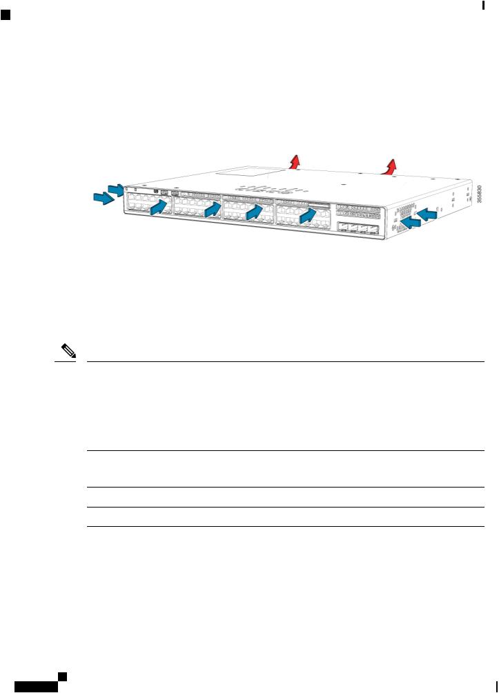
The air circulation system consists of the fan modules and the power supply modules. The airflow patterns vary depending on the power supply configuration. The switch can operate at ambient temperature if one of the fans fail.
Figure 7: Switch Airflow Pattern
The following illustration shows the airflow pattern for the switches. The blue arrow shows cool airflow, and the red arrow shows warm airflow.
Ethernet Management Port
You can connect the switch to a host such as a Windows workstation or a terminal server through the 10/100/1000 Ethernet management port or one of the console ports. The 10/100/1000 Ethernet out-of-band management port is a virtual routing and forwarding (VRF) interface and uses a RJ-45 crossover or straight-through cable.
Note The 10/100/1000 Ethernet management port is an RJ-45 connector that should be connected to a Windows workstation or a terminal server. Do not connect this port to another port in the same switch or to any port within the same switch stack.
The following table shows the Ethernet management port LED colors and their meanings.
Table 6: Ethernet Management Port LED |
|
Color |
Description |
Green |
Link up but no activity. |
Blinking green |
Link up and activity. |
Off |
Link down. |
RJ-45 Console Port
The RJ-45 console port connection uses the supplied RJ-45-to-DB-9 female cable.
Cisco Catalyst 9200 Series Switches Hardware Installation Guide
10

Product Overview
Network Configurations
The following table shows the RJ-45 console port LED colors and their meanings.
Table 7: RJ-45 Console LED |
|
Color |
Description |
Green |
RJ-45 console port is active. |
Off |
The port is not active. |
Network Configurations
See the switch software configuration guide for network configuration concepts and examples of using the switch to create dedicated network segments and interconnecting the segments through Fast Ethernet and Gigabit Ethernet connections.
Cisco Catalyst 9200 Series Switches Hardware Installation Guide
11

Product Overview
Network Configurations
Cisco Catalyst 9200 Series Switches Hardware Installation Guide
12

C H A P T E R 2
Installing the Switch
•Preparing for Installation, on page 13
•Planning a Switch Data Stack , on page 17
•Installing the Switch, on page 21
•Connecting to the StackWise Ports, on page 25
•Connecting Devices to the Ethernet Ports, on page 27
Preparing for Installation
Safety Warnings
This section includes the basic installation caution and warning statements. Read this section before you start the installation procedure. Translations of the warning statements appear in the Regulatory Compliance and Safety Information guide on Cisco.com.
Warning Before working on equipment that is connected to power lines, remove jewelry (including rings, necklaces, and watches). Metal objects will heat up when connected to power and ground and can cause serious burns or weld the metal object to the terminals. Statement 43
Warning Do not stack the chassis on any other equipment. If the chassis falls, it can cause severe bodily injury and equipment damage. Statement 48
Warning Ethernet cables must be shielded when used in a central office environment. Statement 171
Warning Do not work on the system or connect or disconnect cables during periods of lightning activity. Statement 1001
Cisco Catalyst 9200 Series Switches Hardware Installation Guide
13

Installing the Switch
Safety Warnings
Warning Read the installation instructions before connecting the system to the power source. Statement 1004
Warning Class 1 laser product. Statement 1008
Warning This unit is intended for installation in restricted access areas. A restricted access area can be accessed only through the use of a special tool, lock and key, or other means of security. Statement 1017
Warning The plug-socket combination must be accessible at all times, because it serves as the main disconnecting device. Statement 1019
Warning Use copper conductors only. Statement 1025
Warning Thisunitmighthavemorethanonepowersupplyconnection. Allconnectionsmustberemovedtode-energize
the unit. Statement 1028
Warning Onlytrainedandqualifiedpersonnelshouldbeallowedtoinstall,replace,orservicethisequipment. Statement
1030
Warning Ultimate disposal of this product should be handled according to all national laws and regulations. Statement 1040
Warning To prevent the system from overheating, do not operate it in an area that exceeds the maximum recommended ambient temperature of: <113°F (45°C). Statement 1047
Warning Installation of the equipment must comply with local and national electrical codes. Statement 1074
Warning To prevent airflow restriction, allow clearance around the ventilation openings to be at least: 3 inches (7.6 cm). Statement 1076
Cisco Catalyst 9200 Series Switches Hardware Installation Guide
14
Installing the Switch
Installation Guidelines
Installation Guidelines
When determining where to install the switch, verify that these guidelines are met:
•Clearance to the switch front and rear panel meets these conditions:
•Front-panel LEDs can be easily read.
•Access to ports is sufficient for unrestricted cabling.
•AC power cord can reach from the AC power outlet to the connector on the switch rear panel.
•TheSFP/SFP+moduleminimumbendradiusandconnectorlengthismet. SeetheSFP/SFP+module documentation for more information.
•Cabling is away from sources of electrical noise, such as radios, power lines, and fluorescent lighting fixtures. Make sure that the cabling is safely away from other devices that might damage the cables.
•Make sure power-supply modules and fan modules are securely inserted in the chassis before moving the switch.
•Airflow around the switch and through the vents is unrestricted.
•For copper connections on Ethernet ports, cable lengths from the switch to connected devices can be up to 328 feet (100 meters).
•Temperature around the unit does not exceed 113°F (45°C). If the switch is installed in a closed or multirack assembly, the temperature around it might be greater than normal room temperature.
•Humidity around the switch does not exceed 95 percent.
•Altitude at the installation site is not greater than 10,000 feet.
•Cooling mechanisms, such as fans and blowers in the switch, can draw dust and other particles causing contaminant buildup inside the chassis, which can result in system malfunction. You must install this equipment in an environment as free from dust and foreign conductive material (such as metal flakes from construction activities) as is possible.
Note The illustrations used in this section shows a C9200L switch. The C9200 switch installation is similar to C9200L, follow the same steps for installing C9200 switches.
Shipping Box Contents
The shipping box contains the model of the switch you ordered and other components needed for installation. Some components are optional, depending on your order.
Note Verifythatyouhavereceivedtheseitems. Ifanyitemismissingordamaged,contactyourCiscorepresentative or reseller for instructions. Verify that you have received these items. If any item is missing or damaged, contact your Cisco representative or reseller for instructions.
Cisco Catalyst 9200 Series Switches Hardware Installation Guide
15

Installing the Switch
Tools and Equipment
Figure 8: Components delivered in the shipping box
1 |
Cisco Catalyst 9200 Series switch1 (power |
8 |
8 number-8 Phillips flat-head screws |
|
supply modules are not displayed) |
|
|
2 |
AC power cord |
9 |
Cable guide |
3 |
Product documentation and compliance |
10 |
M4.0 x 20mm Phillips pan-head screw |
|
document |
|
|
4 |
Four rubber mounting feet |
11 |
RJ-45 USB console cable1 |
5 |
Two 19-inch mounting brackets |
12 |
(Optional) USB console cable 1 |
6 |
4 number-12 pan-head screw |
13 |
(Optional) StackWise cable1 (0.5-meter, |
|
|
|
1-meter, or 3-meter) |
7 |
4 number-10 pan-head screws |
14 |
Power cord retainer |
1. |
Item is orderable. |
|
|
Tools and Equipment
Obtain these necessary tools:
• A Number-2 Phillips screwdriver to rack-mount the switch
Cisco Catalyst 9200 Series Switches Hardware Installation Guide
16

Installing the Switch
Verifying Switch Operation
Verifying Switch Operation
Before you install the switch in a rack, on a wall, or on a table or shelf, power on the switch and verify that it passes POST.
To power on the switch, plug one end of the AC power cord into the switch AC power connector, and plug the other end into an AC power outlet.
As the switch powers on, it begins the POST, a series of tests that runs automatically to ensure that the switch functions properly. LEDs can blink during the test. POST lasts approximately 1 minute. The SYST LED blinks green, and the other LEDs remain solid green.
When the switch completes POST successfully, the SYST LED remains green. The LEDs turn off and then reflect the switch operating status. If a switch fails POST, the SYST LED turns amber.
POST failures are usually fatal. Call Cisco technical support representative if your switch fails POST.
After a successful POST, unplug the power cord from the switch and install the switch in a rack, on a wall, on a table, or on a shelf.
Planning a Switch Data Stack
Switch Stacking Guidelines
A StackWise adapter must be installed in the stacking port to enable stacking. The StackWise cable connects to the StackWise adapter in the stacking port. If the switch is not ordered with stacking, the adapters must be ordered separately and installed.
Before connecting the switches in a stack, observe these stacking guidelines:
•Number of switches in the stack. You can create data stacks with up to eight switches in a stack.
•Length of the cable. Order the appropriate cable from your Cisco sales representative. The length of FlexStack cable depends on your configuration. These are the different sizes available:
•0.5 meter cable (STACK-T4-50CM)
•1 meter cable (STACK-T4-1M)
•3 meter cable (STACK-T4-3M)
•MinimumbendradiusandcoileddiameterforStackWisecables. Werecommendaminimumbendradius and coiled diameter for each StackWise cable.
Data Stack Cabling Configurations
This is an example of a recommended configuration that uses the supplied 0.5-meter StackWise cable. In this example, the switches are stacked in a vertical rack or on a table. This configuration provides redundant connections. The configuration example uses the supplied 0.5-meter StackWise cable. The example shows the full-ring configuration that provides redundant connections.
Cisco Catalyst 9200 Series Switches Hardware Installation Guide
17
Installing the Switch
Data Stack Bandwidth and Partitioning Examples
Figure 9: Data Stacking the Switches in a Rack or on a Table Using the 0.5-meter StackWise Cables
This example shows a recommended configuration when the switches are mounted side-by-side. Use the 1-meter and the 3-meter StackWise cables to connect the switches. This configuration provides redundant connections.
Figure 10: Data Stacking in a Side-by-Side Mounting
Data Stack Bandwidth and Partitioning Examples
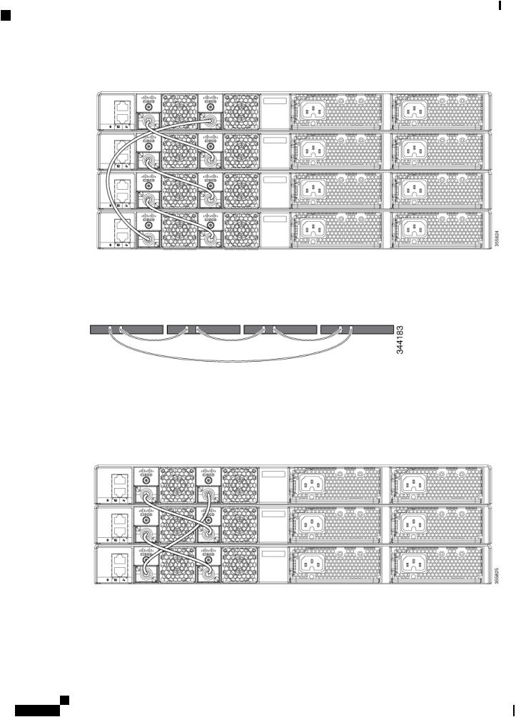
Thissectionprovidesexamplesofdatastackbandwidthandpossibledatastackpartitioning. Thefigureshows a data stack of switches that provides full bandwidth and redundant StackWise cable connections.
Figure 11: Example of a Data Stack with Full Bandwidth Connections
This figure shows an example of a stack of switches with incomplete StackWise cabling connections. This stack provides only half bandwidth and does not have redundant connections.
Cisco Catalyst 9200 Series Switches Hardware Installation Guide
18

Installing the Switch
Data Stack Bandwidth and Partitioning Examples
Figure 12: Example of a Data Stack with Half Bandwidth Connections
The figures below show data stacks of switches with failover conditions. In this figure, the StackWise cable is bad in link 2. Therefore, this stack provides only half bandwidth and does not have redundant connections.
Figure 13: Example of a Data Stack with a Failover Condition
In this figure, link 2 is bad. Therefore, this stack partitions into two stacks, and the top and bottom switches become the active switch in the stack. If the bottom switch is a member (not active or standby switch), it reloads.
Figure 14: Example of a Partitioned Data Stack with a Failover Condition
Cisco Catalyst 9200 Series Switches Hardware Installation Guide
19

Installing the Switch
Power-On Sequence for Switch Stacks
Power-On Sequence for Switch Stacks
Consider these guidelines before you power on the switches in a stack:
•The sequence in which the switches are first powered on might affect the switch that becomes the stack master.
•There are two ways to elect an active switch:
•If you want a particular switch to become the active switch, configure it with the highest priority. Among switches with same priority, the switch with the lowest MAC address becomes the active switch.
•If you want a particular switch to become the active switch, power on that switch first. This switch remains the active switch until a reelection is required. After 2 minutes, power on the other switches in the stack. If you have no preference as to which switch becomes the active switch, power on all the switches in the stack within 1 minute. These switches participate in the active switch election. Switches powered on after 2 minutes do not participate in the election.
•Power off a switch before you add it to or remove it from an existing switch stack. If changes are made to the stack without powering down the switches, the following results can occur:
•If two operating partial ring stacks are connected together using a stack cable, a stack merge can take place. This situation reloads the whole stack (all switches in the stack).
•If some switches in the stack are completely separated from the stack, a stack split can occur.
•A stack split can occur on a full ring stack if:
•More than one running switch is removed without powering down.
•More than one stack cable is removed without powering down.
•A stack split can occur in a partial ring stack if:
•A switch is removed without powering down.
•A stack cable is removed without powering down.
•In a split stack, depending on where the active and standby switches are located, either two stacks might be formed (with the standby taking over as the new active switch in the newly formed stack) or all the members in the newly formed stack might reload.
Note These results depend on how the switches are connected. You can remove two or more switches from the stack without splitting the stack.
Forconditionsthatcancauseastackreelectionortomanuallyelecttheactiveswitch,seethestackingsoftware configurationguide StackManagerandHighAvailabilityConfigurationGuideforCiscoCatalyst9200Series Switches on Cisco.com.
Cisco Catalyst 9200 Series Switches Hardware Installation Guide
20

Installing the Switch
Installing the Switch
Installing the Switch
Rack-Mounting
Installation in racks other than 19-inch racks requires a bracket kit not included with the switch.
Warning To prevent bodily injury when mounting or servicing this unit in a rack, you must take special precautions to ensure that the system remains stable. The following guidelines are provided to ensure your safety:
•This unit should be mounted at the bottom of the rack if it is the only unit in the rack.
•When mounting this unit in a partially filled rack, load the rack from the bottom to the top with the heaviest component at the bottom of the rack.
•If the rack is provided with stabilizing devices, install the stabilizers before mounting or servicing the unit in the rack.
Statement 1006
Figure 15: Rack-Mounting Brackets
This figure shows the standard 19-inch brackets and other optional mounting brackets. You can order the optional brackets (ACC-KIT-T1=) from your Cisco sales representative.
Cisco Catalyst 9200 Series Switches Hardware Installation Guide
21
Loading...