


GETTING STARTED GUIDE
Cisco Catalyst 9120AX Series Access
Points
First Published: June 21, 2019
Last Updated: July 04, 2019
Cisco Systems, Inc. www.cisco.com
1

Cisco Catalyst 9120AX Series Access Points
1About this Guide
2About the Access Point
3Safety Instructions
4Unpacking
5AP Views, Ports, and Connectors
6Preparing the AP for Installation
7Installation Overview
8Performing a Pre-Installation Configuration
9Mounting the Access Point
10Powering the Access Point
11Configuring and Deploying the Access Point
12Checking the Access Point LEDs
13Miscellaneous Usage and Configuration Guidelines
15Related Documentation
16Declarations of Conformity and Regulatory Information Communications, Services, and Additional Information Cisco Bug Search Tool
2

Cisco Catalyst 9120AX Series Access Points
1 About this Guide
This guide provides instructions on how to install your Cisco Catalyst 9120AX series access points and provides links to resources which can help you configure the access point. This guide provides mounting instructions and limited troubleshooting procedures.
The 9120AX series access point is referred to as access point or AP in this document.
2 About the Access Point
The Cisco Catalyst 9120AX series wireless access point is a dual band, dual concurrent, enterprise 802.11ax (Wi-Fi 6) AP. This AP series has integrated antennas designed to use both 2.4 GHz and the 5 GHz bands. This access point supports a greater overall High Density Experience (HDX) which provides a more predictable performance for advanced applications such as 4K or 8K video, high-density and high-definition collaboration applications, all-wireless offices and Internet-of-Things (IoT). The access point supports full interoperability with leading 802.11ax and 802.11ac clients, and supports a mixed deployment with other access points and controllers. These APs provide integrated security, resiliency and operational flexibility as well as increased network intelligence.
A full listing of the access point's features and specifications are provided in the Cisco Catalyst 9120AX Series Access Point Data Sheet, at the following URL:
https://www.cisco.com/c/en/us/products/collateral/wireless/catalyst-9120ax-series-access-points/datasheet-c78-7 42115.html
Access Point Features
The 9120AX series access point is a wireless controller-based product and supports:
Four dual-band integrated antennas on the 9120AXI access point models (C9120AXI-x and C9120AXI-ME-x)
Note The ‘x’ in the model numbers represents the regulatory domain. For information on supported regulatory domains, see the“AP Model Numbers and Regulatory Domains” section on page 5.
Integrated internal antennas, omni directional in azimuth for both 2.4 GHz and 5 GHz
Four radios, a dual band radio with 2.4 GHz (peak gain 4dBi) and 4x4 5 GHz (peak gain 5dBi), a single band 5 GHz (peak gain 5dBi), an omni IoT radio 2.4 GHz (peak gain 3dBi) that can be used with BLE, Zigbee, Thread and other multi-protocol 802.15.4 devices, and an auxiliary radio with 2.4 GHz (peak gain 3dBi) and 5 GHz (peak gain 5dBi)
Simultaneous 4x4 MIMO with four spatial streams for both 2.4 GHz and 5 GHz bands
Multiuser Multiple-Input Multiple-Output (MU-MIMO) technology with 4 spatial streams for downlink.
Orthogonal Frequency Division Multiple Access (OFDMA)-based scheduling for both downlink and uplink
The following hardware external interfaces:
—1x100/1000/2500 Multigigabit Ethernet (RJ-45)
—RS-232 Console Interface through RJ-45
—Recovery push button (enables partial or full system configuration recovery)
—USB 2.0 Port
3

Cisco Catalyst 9120AX Series Access Points
—One multi-color LED Status indicator. see the “Checking the Access Point LEDs” section on page 14 for information on the colors of the LED status indicator.
Integrated Bluetooth Low Energy (BLE) radio to enable IoT use cases such as location tracking and wayfinding.
Cisco RF ASIC, a fully integrated Software Defined Radio (SDR), that can perform advanced RF spectrum analysis and delivers features like CleanAir, Wireless Intrusion Prevention System (WIPS), and DFS detection.
Intelligent Capture probes the network and provides Cisco DNA Center with deep analysis.
Spatial Reuse (also known as Basic Service Set (BSS) coloring) which allows APs and their clients to differentiate between BSSs, thus permitting more simultaneous transmissions.
New power savings mode called Target Wake Time (TWT) which allows the client to stay asleep and wake up only at pre-scheduled (target) times to exchange data with the AP. This provides significant energy savings for battery-operated devices.
Cisco Digital Network Architecture (DNA) support enables Cisco Connected Mobile Experiences, Apple FastLane and Cisco Identity Services Engine.
Cross-AP Noise Reduction, a Cisco innovation that enables APs to intelligently collaborate in real time about RF conditions so that users connect with optimized signal quality and performance.
Optimized AP Roaming for ensuring that client devices associate with the AP in their coverage range that offers the fastest data rate available.
Cisco CleanAir technology enhanced with 160MHz channel support. CleanAir delivers proactive, high-speed spectrum intelligence across 20-, 40-, and 80-, and 160-MHz-wide channels to combat performance problems arising from wireless interference.
MIMO equalization capabilities, which optimize uplink performance and reliability by reducing the impact of signal fade.
The AP supports the following operating modes:
Local—This is the default mode for the Cisco AP. In this mode, the AP serves clients.
FlexConnect—FlexConnect mode for the Cisco AP.
Monitor—This is the monitor-only mode for the Cisco AP.
Sniffer—In the wireless sniffer mode, the AP starts sniffing the air on a given channel. It captures and forwards all the packets from the clients on that channel to a remote machine that runs Airopeek or Wireshark (packet analyzers for IEEE 802.11 wireless LANs). This includes information on the time stamp, signal strength, packet size, etc.
Note In the sniffer mode, the server to which the data is sent should be on the same VLAN as the wireless controller management VLAN otherwise an error will be displayed.
Guidelines and Restrictions for Cisco 802.11ax Access Points
The APs do not support Mobility Express on Cisco AireOS or Cisco IOS-XE platforms.
4

Cisco Catalyst 9120AX Series Access Points
AP Model Numbers and Regulatory Domains
AP Type |
Model Number |
Details |
|
|
|
|
|
Access Point for indoor |
C9120AXI-x |
Dual-band, controller-based 802.11ax |
|
environments, with internal |
|
|
|
C9120AXI-ME-x |
Dual-band, 802.11ax with a Cisco Mobility |
||
antennas |
|||
|
Express software image |
||
|
|
||
|
|
|
You need to verify whether the AP model you have is approved for use in your country. To verify approval and to identify the regulatory domain that corresponds to a particular country, visit http://www.cisco.com/go/aironet/compliance. Not all regulatory domains have been approved. As and when they are approved, this compliance list will be updated.
Antennas and Radios
The 9120AX series access point has four internal dual-band antennas with a dedicated 2.4 GHz radio and a 5 GHz radio, four internal single-band antennas with a dedicated 5 GHz radio, one internal single-band antenna with a dedicated 2.4 GHz IOT radio, and one dual-band antenna with a dedicated 2.4 GHz radio and a 5 GHz AUX radio.
The access point configurations are:
C9120AXI-x—Four radios, a dual band radio with 2.4 GHz (peak gain 4dBi) and 4x4 5 GHz (peak gain 5dBi), a single band 5 GHz (peak gain 5dBi), an omni IoT radio 2.4 GHz (peak gain 3dBi) that can be used with BLE, Zigbee, Thread and other multi-protocol 802.15.4 devices, and an auxiliary radio with 2.4 GHz (peak gain 3dBi) and 5 GHz (peak gain 5dBi).
C9120AXI-ME-x—Four radios, a dual band radio with 2.4 GHz (peak gain 4dBi) and 4x4 5 GHz (peak gain 5dBi), a single band 5 GHz (peak gain 5dBi), an omni IoT radio 2.4 GHz (peak gain 3dBi) that can be used with BLE, Zigbee, Thread and other multi-protocol 802.15.4 devices, and an auxiliary radio with 2.4 GHz (peak gain 3dBi) and 5 GHz (peak gain 5dBi).
3 Safety Instructions
Translated versions of the following safety warnings are provided in the translated safety warnings document that is shipped with your access point. The translated warnings are also in the Translated Safety Warnings for Cisco Catalyst Access Points, which is available on Cisco.com.
Warning |
IMPORTANT SAFETY INSTRUCTIONS |
||
|
|
This warning symbol means danger. You are in a situation that could cause bodily injury. Before you |
|
|
|
work on any equipment, be aware of the hazards involved with electrical circuitry and be familiar with |
|
|
|
standard practices for preventing accidents. Use the statement number provided at the end of each |
|
|
|
warning to locate its translation in the translated safety warnings that accompanied this device. |
|
|
|
SAVE THESE INSTRUCTIONS Statement 1071 |
|
|
|
|
|
|
|
|
|
Warning |
Read the installation instructions before using, installing or connecting the system to the power source. |
||
|
|
Statement 1004 |
|
|
|
|
|
5

Cisco Catalyst 9120AX Series Access Points
Warning
Warning
Warning
Warning
Warning
Installation of the equipment must comply with local and national electrical codes. Statement 1074
In order to comply with FCC radio frequency (RF) exposure limits, antennas should be located at a minimum of 12 inches (30 cm) or more from the body of all persons. Statement 332
Ultimate disposal of this product should be handled according to all national laws and regulations.
Statement 1040
The access point, antennas, and all interconnected equipment including the associated LAN connections must be located indoors within the same building. Statement 375
This equipment is suitable for use in environment air spaces (plenums) in accordance with Section 300.22 (C) of the National Electrical Code, and Sections 2-128, 12-010(3) and 12-100 of the Canadian Electrical Code, Part 1, CSA C22.2. External power supply, power adapter and/or power injector, if provided, are not suitable for installation in air spaces. Statement 440
4 Unpacking
To unpack the access point, follow these steps:
Step 1 Unpack and remove the access point and the accessory kit from the shipping box.
Step 2 Return any packing material to the shipping container and save it for future use.
Step 3 Verify that you have received the items listed below. If any item is missing or damaged, contact your Cisco representative or reseller for instructions.
—The access point
—Mounting bracket (AIR-AP-BRACKET-1=, selected when you ordered the access point)
—Adjustable ceiling-rail clip (selected when you ordered the access point)
—Power Injector AIR-PWRINJ6= (only if selected when you ordered the access point).
6
Cisco Catalyst 9120AX Series Access Points
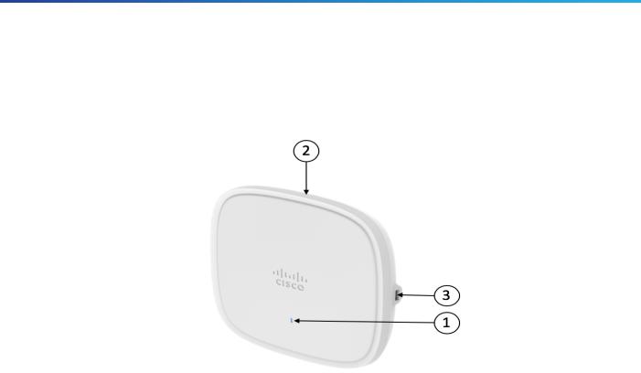
5 AP Views, Ports, and Connectors
Figure 1 Face of the 9120AXI Model
1 |
Status LED |
3 |
USB 2.0 port |
|
|
|
|
2 |
Location of the ports and connectors on the |
|
|
|
head of the AP. |
|
|
|
|
|
|
7

Cisco Catalyst 9120AX Series Access Points
Figure 2 Ports and Connectors on the Head of the 9120AXI Model
1 |
2.5GbE port |
4 |
Mode button |
|
|
|
|
2 |
RJ-45 console port |
|
Security hasp for padlocking AP to mounting |
|
|
5 |
bracket |
|
|
|
|
3 |
USB 2.0 port. |
|
|
|
|
|
|
8

Cisco Catalyst 9120AX Series Access Points
6 Preparing the AP for Installation
Before you mount and deploy your access point, we recommend that you perform a site survey (or use the site planning tool) to determine the best location to install your access point.
You should have the following information about your wireless network available:
Access point locations.
Access point mounting options: below a suspended ceiling, on a flat horizontal surface, or on a desk top.
Note You can mount the access point above a suspended ceiling but you must purchase additional mounting hardware: See “Mounting the Access Point” section on page 12 for additional information.
Access point power options: 802.3at (PoE+) (Cisco Power Injector AIR-PWRINJ6=) or 802.3af (Cisco Power Injector AIR-PWRINJ5=).
Note If 802.3af is used, both the 2.4 GHz and 5 GHz radios will be reduced to 1x1 and Ethernet will be downgraded to 1 GbE. The USB port will also be off.
Operating temperature: 32°—122°F (0°—50°C)
Note When installing the access point in an environment where the ambient temperature is in the range of 104°—122°F (>40°—50°C), the access point must be configured to 2x2 on both the 2.4 GHz and 5 GHz radios, 1GbE Ethernet. Also, there should be no load on the USB port.
Cisco recommends that you make a site map showing access point locations so that you can record the device MAC addresses from each location and return them to the person who is planning or managing your wireless network.
7 Installation Overview
Installing the access point involves these operations:
Step 1 Performing a Pre-Installation Configuration, page 10 (optional)
Step 2 Mounting the Access Point, page 12
Step 3 Powering the Access Point, page 13
Step 4 Preparing the AP for Installation, page 9
9
Cisco Catalyst 9120AX Series Access Points
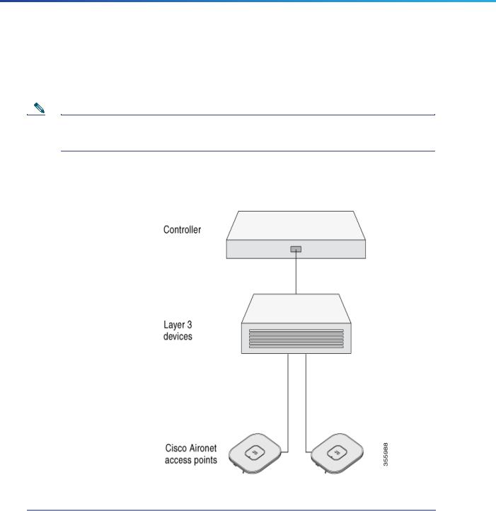
8 Performing a Pre-Installation Configuration
The following procedures ensure that your access point installation and initial operation go as expected. This procedure is optional.
Note Performing a pre-installation configuration is an optional procedure. If your network controller is properly configured, you can install your access point in its final location and connect it to the network from there. See the “Deploying the Access Point on the Wireless Network” section on page 14 for details.
The pre-installation configuration setup is illustrated in Figure 3.
Figure 3 Pre-Installation Configuration Setup
To perform pre-installation configuration, perform the following steps:
Step 1 Make sure that the Cisco Wireless Controller DS port is connected to the network. Use the procedure for CLI or web-browser interface as described in the appropriate Cisco Wireless Controller guide.
a.Make sure that access points have Layer 3 connectivity to the Cisco Wireless Controller Management and AP-Manager Interface.
b.Configure the switch to which your access point is to attach. See the Cisco Wireless Controller Configuration Guide for the release you are using, for additional information.
c.Set the Cisco Wireless Controller as the master so that new access points always join with it.
10
 Loading...