


 Loading...
Catalyst 4948E and Catalyst 4948E-F
Switch Installation Guide
January 2011
Americas Headquarters
Cisco Systems, Inc. 170 West Tasman Drive
San Jose, CA 95134-1706 USA http://www.cisco.com Tel: 408 526-4000
800 553-NETS (6387) Fax: 408 527-0883
Text Part Number: OL-21561-02
THE SPECIFICATIONS AND INFORMATION REGARDING THE PRODUCTS IN THIS MANUAL ARE SUBJECT TO CHANGE WITHOUT NOTICE. ALL STATEMENTS, INFORMATION, AND RECOMMENDATIONS IN THIS MANUAL ARE BELIEVED TO BE ACCURATE BUT ARE PRESENTED WITHOUT WARRANTY OF ANY KIND, EXPRESS OR IMPLIED. USERS MUST TAKE FULL RESPONSIBILITY FOR THEIR APPLICATION OF ANY PRODUCTS.
THE SOFTWARE LICENSE AND LIMITED WARRANTY FOR THE ACCOMPANYING PRODUCT ARE SET FORTH IN THE INFORMATION PACKET THAT SHIPPED WITH THE PRODUCT AND ARE INCORPORATED HEREIN BY THIS REFERENCE. IF YOU ARE UNABLE TO LOCATE THE SOFTWARE LICENSE OR LIMITED WARRANTY, CONTACT YOUR CISCO REPRESENTATIVE FOR A COPY.
The following information is for FCC compliance of Class A devices: This equipment has been tested and found to comply with the limits for a Class A digital device, pursuant to part 15 of the FCC rules. These limits are designed to provide reasonable protection against harmful interference when the equipment is operated in a commercial environment. This equipment generates, uses, and can radiate radio-frequency energy and, if not installed and used in accordance with the instruction manual, may cause harmful interference to radio communications. Operation of this equipment in a residential area is likely to cause harmful interference, in which case users will be required to correct the interference at their own expense.
The following information is for FCC compliance of Class B devices: The equipment described in this manual generates and may radiate radio-frequency energy. If it is not installed in accordance with Cisco’s installation instructions, it may cause interference with radio and television reception. This equipment has been tested and found to comply with the limits for a Class B digital device in accordance with the specifications in part 15 of the FCC rules. These specifications are designed to provide reasonable protection against such interference in a residential installation. However, there is no guarantee that interference will not occur in a particular installation.
Modifying the equipment without Cisco’s written authorization may result in the equipment no longer complying with FCC requirements for Class A or Class B digital devices. In that event, your right to use the equipment may be limited by FCC regulations, and you may be required to correct any interference to radio or television communications at your own expense.
You can determine whether your equipment is causing interference by turning it off. If the interference stops, it was probably caused by the Cisco equipment or one of its peripheral devices. If the equipment causes interference to radio or television reception, try to correct the interference by using one or more of the following measures:
•Turn the television or radio antenna until the interference stops.
•Move the equipment to one side or the other of the television or radio.
•Move the equipment farther away from the television or radio.
•Plug the equipment into an outlet that is on a different circuit from the television or radio. (That is, make certain the equipment and the television or radio are on circuits controlled by different circuit breakers or fuses.)
Modifications to this product not authorized by Cisco Systems, Inc. could void the FCC approval and negate your authority to operate the product.
The Cisco implementation of TCP header compression is an adaptation of a program developed by the University of California, Berkeley (UCB) as part of UCB’s public domain version of the UNIX operating system. All rights reserved. Copyright © 1981, Regents of the University of California.
NOTWITHSTANDING ANY OTHER WARRANTY HEREIN, ALL DOCUMENT FILES AND SOFTWARE OF THESE SUPPLIERS ARE PROVIDED “AS IS” WITH ALL FAULTS. CISCO AND THE ABOVE-NAMED SUPPLIERS DISCLAIM ALL WARRANTIES, EXPRESSED OR IMPLIED, INCLUDING, WITHOUT LIMITATION, THOSE OF MERCHANTABILITY, FITNESS FOR A PARTICULAR PURPOSE AND NONINFRINGEMENT OR ARISING FROM A COURSE OF DEALING, USAGE, OR TRADE PRACTICE.
IN NO EVENT SHALL CISCO OR ITS SUPPLIERS BE LIABLE FOR ANY INDIRECT, SPECIAL, CONSEQUENTIAL, OR INCIDENTAL DAMAGES, INCLUDING, WITHOUT LIMITATION, LOST PROFITS OR LOSS OR DAMAGE TO DATA ARISING OUT OF THE USE OR INABILITY TO USE THIS MANUAL, EVEN IF CISCO OR ITS SUPPLIERS HAVE BEEN ADVISED OF THE POSSIBILITY OF SUCH DAMAGES.
Cisco and the Cisco Logo are trademarks of Cisco Systems, Inc. and/or its affiliates in the U.S. and other countries. A listing of Cisco's trademarks can be found at www.cisco.com/go/trademarks. Third party trademarks mentioned are the property of their respective owners. The use of the word partner does not imply a partnership relationship between Cisco and any other company. (1005R)
Catalyst 4948E and Catalyst 4948E-F Switch Installation Guide
© 2010–2011 Cisco Systems, Inc. All rights reserved.

C O N T E N T S
|
|
Preface ix |
|
|
|
|
|
|
|
|
|
Audience |
i-ix |
|
|
|
|
|
|
|
|
Organization |
i-ix |
|
|
|
|
|
|
|
|
Related Documentation |
i-x |
|
|
|
|||
|
|
Command Syntax Conventions |
i-x |
|
|
||||
|
|
Statement 1071—Warning Definition |
i-xi |
|
|||||
|
|
Obtaining Documentation and Submitting a Service Request i-xvi |
|||||||
|
|
Product Overview |
|
|
|
|
|
||
C H A P T E R |
1 |
1-1 |
|
|
|
|
|||
|
|
Features |
1-3 |
|
|
|
|
|
|
|
|
Physical and Environmental Specifications |
1-7 |
|
|||||
|
|
Fan Tray |
1-8 |
|
|
|
|
|
|
|
|
Catalyst 4948E Fan Tray (WS-X4993=) |
1-8 |
|
|||||
|
|
Catalyst 4948E-F Fan Tray (WS-X4993-F=) |
1-9 |
||||||
|
|
Front Panel LEDs |
1-11 |
|
|
|
|
||
|
|
Preparing for Installation |
|
|
|
|
|||
C H A P T E R |
2 |
2-1 |
|
|
|
||||
|
|
Safety |
2-1 |
|
|
|
|
|
|
|
|
Site Requirements |
2-2 |
|
|
|
|
||
|
|
Rack-Mounting Guidelines |
2-2 |
|
|
||||
|
|
Temperature |
2-3 |
|
|
|
|
||
|
|
Air Flow |
2-4 |
|
|
|
|
|
|
|
|
Humidity |
2-5 |
|
|
|
|
|
|
|
|
Altitude |
2-5 |
|
|
|
|
|
|
|
|
Dust and Particulates |
2-5 |
|
|
|
|||
|
|
Corrosion |
2-6 |
|
|
|
|
||
|
|
Electromagnetic and Radio Frequency Interference 2-6 |
|||||||
|
|
Shock and Vibration |
2-7 |
|
|
|
|||
|
|
Power Source Interruptions 2-7 |
|
|
|
||||
|
|
System Grounding |
2-7 |
|
|
|
|
||
|
|
Maintaining Safety with Electricity |
2-9 |
|
|||||
|
|
Preventing Electrostatic Discharge Damage |
2-10 |
||||||
|
Power Requirements |
2-11 |
|
|
|
|
|
Catalyst 4948E and Catalyst 4948E-F Switch Installation Guide |
|
|
|
|
|
|
|||
|
|
|
|
|
|
|
OL-21561-02 |
|
|
iii |
|
|
|
|
|

Contents
|
|
|
|
|
Power Connection Guidelines for AC-Powered Systems |
2-12 |
|
||||||||
|
|
|
|
|
Power Connection Guidelines for DC-Powered Systems |
2-12 |
|
||||||||
|
|
|
|
|
Cabling Requirements |
2-13 |
|
|
|
|
|
|
|
|
|
|
|
|
|
|
Site Preparation Checklist |
2-13 |
|
|
|
|
|
|
|
||
|
|
|
Installing the Switch |
|
|
|
|
|
|
|
|
|
|
||
C H A P T E R |
3 |
|
3-1 |
|
|
|
|
|
|
|
|
|
|||
|
|
|
|
|
Preparing to Install the Chassis |
3-1 |
|
|
|
|
|
|
|||
|
|
|
|
|
Warnings 3-2 |
|
|
|
|
|
|
|
|
|
|
|
|
|
|
|
Verifying Package Contents |
3-4 |
|
|
|
|
|
|
|||
|
|
|
|
|
Required Tools |
3-4 |
|
|
|
|
|
|
|
|
|
|
|
|
|
|
Lifting the Chassis Safely |
3-5 |
|
|
|
|
|
|
|||
|
|
|
|
|
Rack-Mounting the Chassis |
3-5 |
|
|
|
|
|
|
|||
|
|
|
|
|
Attaching the Rack-Mount Brackets to the Chassis 3-6 |
|
|
||||||||
|
|
|
|
|
Installing the Chassis in the Rack |
3-7 |
|
|
|
|
|||||
|
|
|
|
|
Installing the Cable Guide (Optional) |
3-8 |
|
|
|
|
|||||
|
|
|
|
|
Installing the Catalyst 4948E-F Switch Chassis with the Optional Panduit Air Duct Kit 3-9 |
||||||||||
|
|
|
|
|
Installing the System Ground |
3-10 |
|
|
|
|
|
|
|||
|
|
|
|
|
Connecting Power to the Switch |
3-12 |
|
|
|
|
|
||||
|
|
|
|
|
Connecting AC Source Power to the Switch |
3-12 |
|
|
|||||||
|
|
|
|
|
Connecting DC Source Power to the Switch |
3-13 |
|
|
|||||||
|
|
|
|
|
Attaching the Interface Cables |
3-15 |
|
|
|
|
|
|
|||
|
|
|
|
|
Connecting to the Downlink Ports |
3-16 |
|
|
|
|
|||||
|
|
|
|
|
Installing Uplink Port Transceivers and Cables |
3-16 |
|
|
|||||||
|
|
|
|
|
Connecting to the Ethernet Management Port |
3-20 |
|
|
|||||||
|
|
|
|
|
Connecting to the Console Port |
3-20 |
|
|
|
|
|||||
|
|
|
|
|
Powering Up the Switch |
3-21 |
|
|
|
|
|
|
|
||
|
|
|
|
|
Starting the Terminal-Emulation Software |
3-21 |
|
|
|||||||
|
|
|
|
|
Powering Up the Switch |
3-21 |
|
|
|
|
|
|
|||
|
|
|
Removal and Replacement Procedures |
|
|
|
|
|
|||||||
C H A P T E R |
4 |
|
4-1 |
|
|
|
|
||||||||
|
|
|
|
|
Removing and Installing the DC-Input Power Supply |
4-2 |
|
|
|||||||
|
|
|
|
|
Required Tools |
4-2 |
|
|
|
|
|
|
|
|
|
|
|
|
|
|
Removing the DC-Input Power Supply |
4-2 |
|
|
|
|
|||||
|
|
|
|
|
Installing the DC-Input Power Supply |
4-5 |
|
|
|
|
|||||
|
|
|
|
|
Removing and Installing the AC-Input Power Supply |
4-8 |
|
|
|||||||
|
|
|
|
|
Required Tools |
4-8 |
|
|
|
|
|
|
|
|
|
|
|
|
|
|
Removing the AC-Input Power Supply |
4-8 |
|
|
|
|
|||||
|
|
|
|
|
Installing the AC-Input Power Supply |
4-9 |
|
|
|
|
|||||
|
|
|
|
Catalyst 4948E and Catalyst 4948E-F Switch Installation Guide |
|
|
|
|
|
|
|||||
|
|
|
|
|
|
|
|
|
|
||||||
|
|
|
|
|
|
|
|
|
|
|
|
|
|
|
|
|
iv |
|
|
|
|
|
|
|
|
|
|
|
|
OL-21561-02 |
|
|
|
|
|
|
|
|
|
|
|
|
|
|
|
||

Contents
|
|
|
Removing and Installing the Fan Tray |
4-10 |
|
|
|
|
|
|
|||
|
|
|
Required Tools |
4-10 |
|
|
|
|
|
|
|
|
|
|
|
|
Removing the Fan Tray |
4-10 |
|
|
|
|
|
|
|
||
|
|
|
Installing the Fan Tray |
4-11 |
|
|
|
|
|
|
|
||
|
|
Power Supply Specifications |
|
|
|
|
|
|
|
|
|||
A P P E N D I X |
A |
A-1 |
|
|
|
|
|
|
|
||||
|
|
|
300 W AC-Input Power Supply (PWR-C49E-300AC-R) |
A-1 |
|||||||||
|
|
|
300 W AC-Input Power Supply (PWR-C49E-300AC-F) |
A-5 |
|||||||||
|
|
|
300 W AC-Input Power Supply Power Cords |
A-8 |
|
|
|
|
|
||||
|
|
|
300 W DC-Input Power Supply (PWR-C49-300DC) |
A-12 |
|||||||||
|
|
Transceiver, Chassis Connectors, and Cable and Adapter Specifications B-1 |
|||||||||||
A P P E N D I X |
B |
||||||||||||
|
|
|
Transceiver Support for Uplink Ports |
B-1 |
|
|
|
|
|
|
|||
|
|
|
1-GB SFP Transceivers |
B-1 |
|
|
|
|
|
|
|
||
|
|
|
CWDM SFP Transceivers |
B-5 |
|
|
|
|
|
|
|
||
|
|
|
DWDM SFP Transceivers |
B-7 |
|
|
|
|
|
|
|
||
|
|
|
10-GB SFP+ Transceivers |
B-9 |
|
|
|
|
|
|
|
||
|
|
|
Console Port |
B-11 |
|
|
|
|
|
|
|
|
|
|
|
|
Ethernet Management Port |
B-12 |
|
|
|
|
|
|
|
||
|
|
|
Cables and Adapters |
B-12 |
|
|
|
|
|
|
|
|
|
|
|
|
Rollover Cable |
B-12 |
|
|
|
|
|
|
|
|
|
|
|
|
Rollover Cable RJ-45 to DB-9 Adapter (For Connecting to a PC) B-13 |
||||||||||
|
|
Troubleshooting the Installation C-1 |
|
|
|
|
|
|
|||||
A P P E N D I X |
C |
|
|
|
|
|
|
||||||
|
|
|
Getting Started |
C-2 |
|
|
|
|
|
|
|
|
|
|
|
|
Problem Solving to the System Component Level |
C-2 |
|||||||||
|
|
|
Identifying Startup Problems |
C-2 |
|
|
|
|
|
|
|
||
|
|
|
LED Readings |
C-3 |
|
|
|
|
|
|
|
|
|
|
|
|
Troubleshooting the Power Supply |
C-4 |
|
|
|
|
|
|
|||
|
|
|
Contacting Customer Service |
C-4 |
|
|
|
|
|
|
|
||
|
|
Regulatory Compliance and Safety Information |
|
|
|
|
|
||||||
A P P E N D I X |
D |
D-1 |
|
|
|
|
|||||||
|
|
|
Translated Safety Warnings |
D-2 |
|
|
|
|
|
|
|
||
|
|
|
Statement 17—Overtemperature Warning |
D-2 |
|
|
|
|
|||||
|
|
|
Statement 37—Restricted Area Warning |
D-3 |
|
|
|
|
|||||
|
|
|
Statement 39—Grounded Equipment Warning |
D-4 |
|||||||||
|
|
|
Statement 43—Jewelry Removal Warning |
D-5 |
|
|
|
|
|||||
|
|
|
Statement 48—Stacking the Chassis Warning |
D-8 |
|||||||||
|
|
|
|
|
|
|
Catalyst 4948E and Catalyst 4948E-F Switch Installation Guide |
|
|
|
|||
|
|
|
|
|
|
|
|
||||||
|
|
|
|
|
|
|
|
|
|
|
|
|
|
|
OL-21561-02 |
|
|
|
|
|
|
|
|
|
|
v |
|
|
|
|
|
|
|
|
|
|
|
|
|
||

Contents
Statement 171—Ethernet Cable Shielding in Offices |
D-9 |
|
|
|||
Statement 258—Fan Tray Removal Warning |
D-10 |
|
|
|
||
Statement 322—DC Power Off Warning |
D-11 |
|
|
|
||
Statement 1001—Work During Lightning Activity |
D-12 |
|
|
|||
Statement 1003—DC Power Disconnection |
D-13 |
|
|
|
||
Statement 1004—Installation Instructions |
D-15 |
|
|
|
||
Statement 1006—Chassis Warning for Rack-Mounting and Servicing |
D-16 |
|
||||
Statement 1008—Class 1 Laser Product |
D-22 |
|
|
|
||
Statement 1017—Restricted Area |
D-23 |
|
|
|
|
|
Statement 1019—Main Disconnecting Device |
D-25 |
|
|
|||
Statement 1030—Equipment Installation |
D-26 |
|
|
|
||
Statement 1040—Product Disposal |
D-28 |
|
|
|
|
|
Statement 1045—Short-circuit Protection |
D-30 |
|
|
|
||
Statement 1046—Installing or Replacing the Unit |
D-32 |
|
|
|||
Statement 1051—Laser Radiation |
D-33 |
|
|
|
|
|
Statement 1072—Shock Hazard from Interconnections D-35 |
|
|
||||
Statement 1074—Comply with Local and National Electrical Codes |
D-37 |
|
||||
Statement 1075—Hazardous Voltage or Energy Present on DC Power Terminals |
D-39 |
|||||
Regulatory Standards Compliance D-40 |
|
|
|
|
|
|
GR-1089-CORE Issue 3 Documentation Statements |
D-42 |
|
|
|||
Statement 7016—GR-1089-Core Intrabuilding Lightning—Immunity Requirements |
D-42 |
|||||
GR-1089-CORE Issue 4 Documentation Statements |
D-42 |
|
|
|||
Statement 7001—ESD Mitigation |
D-42 |
|
|
|
|
|
Statement 7005—Intra-building Lightning Surge and AC Power Fault
Statement 7012—Equipment Interfacing with AC Power Ports
Statement 7013—Equipment Bonding Networks
Statement 7014—Installation Location D-42
Statement 7015—Equipment Bonding and Grounding
Statement 7016—Battery Return Conductor D-43
Statement 7017—Minimum Steady State DC Input Voltage
European Directives D-43
Statement 2002—Declaration of Conformity with Regard to the Directives 2006/95/EC and 2004/108/EC
Statement 6005—California Perchlorate Contamination Prevention Act (Title 22, California Code of
Regulations, Chapter 33)
EMC Class A Notices and Warnings D-44
|
|
|
Statement 2017—Class A Notice for FCC D-44 |
|
|
|
|
|
Statement 2021—Class A Notice for Canada D-44 |
|
|
|
|
|
Statement 191—VCCI Class A Warning for Japan |
D-44 |
|
|
|
|
Catalyst 4948E and Catalyst 4948E-F Switch Installation Guide |
|
|
|
|
|
|
|
|
|
|
|
|
|
|
|
vi |
|
|
OL-21561-02 |
|
|
|
|
|
||

Contents
Statement 256—Class A Warning for Hungary D-45
Statement 257—Class A Notice for Taiwan and Other Traditional Chinese Markets D-45
Statement 294—Class A Warning for Korea
Statement 340—Class A Warning for CISPR22
Statement 371—Power Cable and AC Adapter
I N D E X
Catalyst 4948E and Catalyst 4948E-F Switch Installation Guide
|
OL-21561-02 |
vii |
|

Contents
Catalyst 4948E and Catalyst 4948E-F Switch Installation Guide
|
viii |
OL-21561-02 |
|
|
|

Preface
This preface describes the audience, organization, and conventions of the Catalyst 4948E and Catalyst 4948E-F Switch Installation Guide and provides information on how to obtain related documentation.
Audience
Only trained and qualified service personnel (as defined in IEC60950-1 and AZ/NZS 60950-1) should install, replace, or service the equipment.
Organization
This guide is organized as follows:
Chapter |
Title |
Description |
|
|
|
Chapter 1 |
Product Overview |
Describes the hardware features, specifications, and |
|
|
functionality of the Catalyst 4948E and |
|
|
Catalyst 4948E-F switches. |
|
|
|
Chapter 2 |
Preparing for |
Describes how to prepare your site for the installation of |
|
Installation |
the Catalyst 4948E and Catalyst 4948E-F switches. |
|
|
|
Chapter 3 |
Installing the Switch |
Describes how to rack-mount the Catalyst 4948E and the |
|
|
Catalyst 4948E-F switches and attach the cables. |
|
|
|
Chapter 4 |
Removal and |
Describes how to remove and install the field replaceable |
|
Replacement |
units on the Catalyst 4948E and Catalyst 4948E-F |
|
Procedures |
switches. |
|
|
|
Appendix A |
Power Supply |
Lists the switch system specifications. |
|
Specifications |
|
|
|
|
Appendix B |
Transceiver, Chassis |
Describes the SFP and SFP+ transceivers, the chassis |
|
Connectors, and Cable |
connectors, and the cables and adapters supplied with the |
|
and Adapter |
Catalyst 4948E and Catalyst 4948E-F switches. |
|
Specifications |
|
|
|
|
Catalyst 4948E and Catalyst 4948E-F Switch Installation Guide
|
OL-21561-02 |
ix |
|

Preface
Related Documentation
Chapter |
Title |
Description |
|
|
|
Appendix C |
Troubleshooting the |
Provides some basic troubleshooting techniques for the |
|
Installation |
Catalyst 4948E and Catalyst 4948E-F switches. |
|
|
|
Appendix D |
Regulatory Compliance |
States compliance information for the Catalyst 4948E |
|
and Safety Information |
and Catalyst 4948E-F switches and provides multiple |
|
|
language translations for the warnings in this guide. |
|
|
|
Related Documentation
The Catalyst 4900 series switches use software that also runs on the Catalyst 4500 series switches. Refer to the version of these documents appropriate for your software release:
•Catalyst 4500 Series Switch Cisco IOS Software Configuration Guide http://www.cisco.com/en/US/products/hw/switches/ps4324/products_installation_and_configurati on_guides_list.html
•Catalyst 4500 Series Switch Cisco IOS Command Reference http://www.cisco.com/en/US/products/hw/switches/ps4324/prod_command_reference_list.html
•Catalyst 4500 Series Switch Cisco IOS System Message Guide http://www.cisco.com/en/US/products/hw/switches/ps4324/products_system_message_guides_list
.html
A specific release note for the Catalyst 4900 switches is available at:
http://www.cisco.com/en/US/docs/switches/lan/catalyst4500/release/note/OL_9592.html
Command Syntax Conventions
Table 1 describes the syntax used with the commands in this document.
Table 1 |
Command Syntax Guide |
|
|
|
|
Convention |
|
Description |
|
|
|
boldface |
|
Commands and keywords. |
|
|
|
italic |
|
Command input that is supplied by you. |
|
|
|
[ ] |
|
Keywords or arguments that appear within square |
|
|
brackets are optional. |
|
|
|
{ x | x | x } |
|
A choice of keywords (represented by x) appears in |
|
|
braces separated by vertical bars. You must select one. |
|
|
|
^ or Ctrl |
|
Represent the key labeled Control. For example, when |
|
|
you read ^D or Ctrl-D, you should hold down the |
|
|
Control key while you press the D key. |
|
|
|
screen font |
|
Terminal sessions and information the system displays |
|
|
are in screen font. |
|
|
|
boldface screen font |
Information you must enter is in boldface screen |
|
|
|
font. |
|
|
|
Catalyst 4948E and Catalyst 4948E-F Switch Installation Guide
|
x |
OL-21561-02 |
|
|
|
Preface
Command Syntax Conventions
Table 1 |
Command Syntax Guide |
||
|
|
|
|
Convention |
|
Description |
|
|
|
|
|
< |
> |
|
Nonprinting characters, such as passwords, appear in |
|
|
|
angled brackets. |
|
|
|
|
[ |
] |
|
Default responses to system prompts appear in square |
|
|
|
brackets. |
|
|
|
|
Note Means reader take note.
Tip Means the following information will help you solve a problem.
Caution Means reader be careful. In this situation, you might perform an action that could result in equipment damage or loss of data.
Warning Means reader be warned. In this situation, you might perform an action that could result in bodily injury.
Statement 1071—Warning Definition
Warning IMPORTANT SAFETY INSTRUCTIONS
This warning symbol means danger. You are in a situation that could cause bodily injury. Before you work on any equipment, be aware of the hazards involved with electrical circuitry and be familiar with standard practices for preventing accidents. Use the statement number provided at the end of each warning to locate its translation in the translated safety warnings that accompanied this device.
SAVE THESE INSTRUCTIONS
Waarschuwing BELANGRIJKE VEILIGHEIDSINSTRUCTIES
Dit waarschuwingssymbool betekent gevaar. U verkeert in een situatie die lichamelijk letsel kan veroorzaken. Voordat u aan enige apparatuur gaat werken, dient u zich bewust te zijn van de bij elektrische schakelingen betrokken risico's en dient u op de hoogte te zijn van de standaard praktijken om ongelukken te voorkomen. Gebruik het nummer van de verklaring onderaan de waarschuwing als u een vertaling van de waarschuwing die bij het apparaat wordt geleverd, wilt raadplegen.
BEWAAR DEZE INSTRUCTIES
Catalyst 4948E and Catalyst 4948E-F Switch Installation Guide
|
OL-21561-02 |
xi |
|

Preface
Command Syntax Conventions
Varoitus TÄRKEITÄ TURVALLISUUSOHJEITA
Tämä varoitusmerkki merkitsee vaaraa. Tilanne voi aiheuttaa ruumiillisia vammoja. Ennen kuin käsittelet laitteistoa, huomioi sähköpiirien käsittelemiseen liittyvät riskit ja tutustu onnettomuuksien yleisiin ehkäisytapoihin. Turvallisuusvaroitusten käännökset löytyvät laitteen mukana toimitettujen käännettyjen turvallisuusvaroitusten joukosta varoitusten lopussa näkyvien lausuntonumeroiden avulla.
SÄILYTÄ NÄMÄ OHJEET
Attention IMPORTANTES INFORMATIONS DE SÉCURITÉ
Ce symbole d'avertissement indique un danger. Vous vous trouvez dans une situation pouvant entraîner des blessures ou des dommages corporels. Avant de travailler sur un équipement, soyez conscient des dangers liés aux circuits électriques et familiarisez-vous avec les procédures couramment utilisées pour éviter les accidents. Pour prendre connaissance des traductions des avertissements figurant dans les consignes de sécurité traduites qui accompagnent cet appareil, référez-vous au numéro de l'instruction situé à la fin de chaque avertissement.
CONSERVEZ CES INFORMATIONS
Warnung WICHTIGE SICHERHEITSHINWEISE
Dieses Warnsymbol bedeutet Gefahr. Sie befinden sich in einer Situation, die zu Verletzungen führen kann. Machen Sie sich vor der Arbeit mit Geräten mit den Gefahren elektrischer Schaltungen und den üblichen Verfahren zur Vorbeugung vor Unfällen vertraut. Suchen Sie mit der am Ende jeder Warnung angegebenen Anweisungsnummer nach der jeweiligen Übersetzung in den übersetzten Sicherheitshinweisen, die zusammen mit diesem Gerät ausgeliefert wurden.
BEWAHREN SIE DIESE HINWEISE GUT AUF.
Avvertenza IMPORTANTI ISTRUZIONI SULLA SICUREZZA
Questo simbolo di avvertenza indica un pericolo. La situazione potrebbe causare infortuni alle persone. Prima di intervenire su qualsiasi apparecchiatura, occorre essere al corrente dei pericoli relativi ai circuiti elettrici e conoscere le procedure standard per la prevenzione di incidenti. Utilizzare il numero di istruzione presente alla fine di ciascuna avvertenza per individuare le traduzioni delle avvertenze riportate in questo documento.
CONSERVARE QUESTE ISTRUZIONI
Advarsel VIKTIGE SIKKERHETSINSTRUKSJONER
Dette advarselssymbolet betyr fare. Du er i en situasjon som kan føre til skade på person. Før du begynner å arbeide med noe av utstyret, må du være oppmerksom på farene forbundet med elektriske kretser, og kjenne til standardprosedyrer for å forhindre ulykker. Bruk nummeret i slutten av hver advarsel for å finne oversettelsen i de oversatte sikkerhetsadvarslene som fulgte med denne enheten.
TA VARE PÅ DISSE INSTRUKSJONENE
Catalyst 4948E and Catalyst 4948E-F Switch Installation Guide
|
xii |
OL-21561-02 |
|
|
|
Preface
Command Syntax Conventions
Aviso INSTRUÇÕES IMPORTANTES DE SEGURANÇA
Este símbolo de aviso significa perigo. Você está em uma situação que poderá ser causadora de lesões corporais. Antes de iniciar a utilização de qualquer equipamento, tenha conhecimento dos perigos envolvidos no manuseio de circuitos elétricos e familiarize-se com as práticas habituais de prevenção de acidentes. Utilize o número da instrução fornecido ao final de cada aviso para localizar sua tradução nos avisos de segurança traduzidos que acompanham este dispositivo.
GUARDE ESTAS INSTRUÇÕES
¡Advertencia! INSTRUCCIONES IMPORTANTES DE SEGURIDAD
Este símbolo de aviso indica peligro. Existe riesgo para su integridad física. Antes de manipular cualquier equipo, considere los riesgos de la corriente eléctrica y familiarícese con los procedimientos estándar de prevención de accidentes. Al final de cada advertencia encontrará el número que le ayudará a encontrar el texto traducido en el apartado de traducciones que acompaña a este dispositivo.
GUARDE ESTAS INSTRUCCIONES
Varning! VIKTIGA SÄKERHETSANVISNINGAR
Denna varningssignal signalerar fara. Du befinner dig i en situation som kan leda till personskada. Innan du utför arbete på någon utrustning måste du vara medveten om farorna med elkretsar och känna till vanliga förfaranden för att förebygga olyckor. Använd det nummer som finns i slutet av varje varning för att hitta dess översättning i de översatta säkerhetsvarningar som medföljer denna anordning.
SPARA DESSA ANVISNINGAR
Catalyst 4948E and Catalyst 4948E-F Switch Installation Guide
|
OL-21561-02 |
xiii |
|

Preface
Command Syntax Conventions
Aviso INSTRUÇÕES IMPORTANTES DE SEGURANÇA
Este símbolo de aviso significa perigo. Você se encontra em uma situação em que há risco de lesões corporais. Antes de trabalhar com qualquer equipamento, esteja ciente dos riscos que envolvem os circuitos elétricos e familiarize-se com as práticas padrão de prevenção de acidentes. Use o número da declaração fornecido ao final de cada aviso para localizar sua tradução nos avisos de segurança traduzidos que acompanham o dispositivo.
GUARDE ESTAS INSTRUÇÕES
Advarsel VIGTIGE SIKKERHEDSANVISNINGER
Dette advarselssymbol betyder fare. Du befinder dig i en situation med risiko for legemesbeskadigelse. Før du begynder arbejde på udstyr, skal du være opmærksom på de involverede risici, der er ved elektriske kredsløb, og du skal sætte dig ind i standardprocedurer til undgåelse af ulykker. Brug erklæringsnummeret efter hver advarsel for at finde oversættelsen i de oversatte advarsler, der fulgte med denne enhed.
GEM DISSE ANVISNINGER
Catalyst 4948E and Catalyst 4948E-F Switch Installation Guide
|
xiv |
OL-21561-02 |
|
|
|

Preface
Command Syntax Conventions
Catalyst 4948E and Catalyst 4948E-F Switch Installation Guide
|
OL-21561-02 |
xv |
|
Preface
Obtaining Documentation and Submitting a Service Request
Obtaining Documentation and Submitting a Service Request
For information on obtaining documentation, submitting a service request, and gathering additional information, see the monthly What’s New in Cisco Product Documentation, which also lists all new and revised Cisco technical documentation, at:
http://www.cisco.com/en/US/docs/general/whatsnew/whatsnew.html
Subscribe to the What’s New in Cisco Product Documentation as a Really Simple Syndication (RSS) feed and set content to be delivered directly to your desktop using a reader application. The RSS feeds are a free service and Cisco currently supports RSS version 2.0.
Catalyst 4948E and Catalyst 4948E-F Switch Installation Guide
|
xvi |
OL-21561-02 |
|
|
|

C H A P T E R 1
Product Overview
Revised: January 4, 2012
Both the Catalyst 4948E switch and the Catalyst 4948E-F switch are 1-RU, horizontal, fixed-configuration chassis with 48 10/100/1000 downlink ports and 4 1-GB or 10-GB uplink ports. Both switches have one removable fan tray and support redundant power supplies. The primary difference between the two chassis is that the air flow in the Catalyst 4948E goes from the front of the chassis to the rear of the chassis while the air flow in the Catalyst 4948E-F goes from the rear of the chassis to the front of the chassis. Figure 1-1 shows the front view of both chassis with the major features identified and Figure 1-2 shows the rear view of both chassis with the major features identified.
Note The fan trays and the power supplies are not interchangeable between the Catalyst 4948E and the Catalyst 4948E-F switch chassis.
Tip For additional information about the Cisco Catalyst 4948E and the Catalyst 4948E-F switches (including configuration examples and troubleshooting information), see the documents listed on this page:
http://www.cisco.com/en/US/products/ps6021/tsd_products_support_series_home.html
Catalyst 4948E and Catalyst 4948E-F Switch Installation Guide
|
OL-21561-02 |
1-1 |
|
|
|
Chapter 1 Product Overview
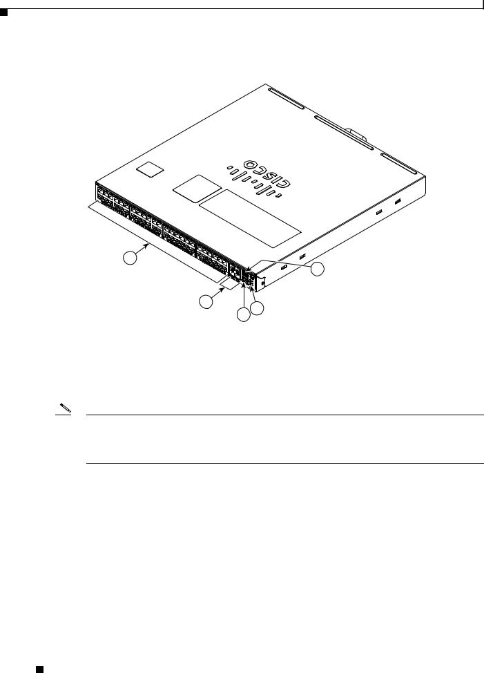
Figure 1-1 Catalyst 4948E and Catalyst 4948E-F Switches—Front View of Chassis (Catalyst 4948E Switch Shown)
278083
1
5
|
2 |
4 |
|
|
|
3 |
|
|
|
|
|
|
|
|
1 |
48 downlink ports |
|
4 |
Status LEDs |
|
|
|
|
|
2 |
4 uplink ports |
|
5 |
Console port |
|
|
|
|
|
3 |
Management port |
|
|
|
|
|
|
|
|
Note The orientation of the Cisco logo shown in Figure 1-1 identifies the chassis as a Catalyst 4948E switch. The Cisco logo that appears on the Catalyst 4948E-F chassis top cover is rotated 180 degrees. Additional labels are placed on the Catalyst 4948E-F top cover to denote the direction of the airflow through the chassis.
Catalyst 4948E and Catalyst 4948E-F Switch Installation Guide
1-2 |
OL-21561-02 |
|
|

Chapter 1 Product Overview
Features
Figure 1-2 Catalyst 4948E and Catalyst 4948E-F Switches—Rear View of Chassis
PWR - 540 AC |
|
100 - 240 VAC |
|
|
7 - 3A |
50 - 60 Hz |
|
INPUT |
OUTPUT |
OK |
|
|
OK |
1
PWR - 540 AC |
|
100 - 240 VAC |
|
|
7 - 3A |
50 - 60 Hz |
|
INPUT |
OUTPUT |
OK |
|
|
OK |
2
3
 330680
1 |
Power supply 1 (primary) |
3 |
Power supply 2 (redundant) |
|
|
|
|
2 |
Fan tray |
|
|
|
|
|
|
This chapter describes the Catalyst 4948E and Catalyst 4948E-F switches and includes these sections:
•Features, page 1-3
•Physical and Environmental Specifications, page 1-7
•Fan Tray, page 1-8
•Front Panel LEDs, page 1-11
Features
Table 1-1 lists the features of the Catalyst 4948E and the Catalyst 4948E-F switch chassis.
Catalyst 4948E and Catalyst 4948E-F Switch Installation Guide
|
OL-21561-02 |
1-3 |
|
|
|

Chapter 1 Product Overview
Features
Table 1-1 |
Catalyst 4948E and Catalyst 4948E-F Switch Features |
|
|
|
|
Feature |
|
Description |
|
|
|
Chassis |
|
1-RU, 48 10/100/1000 ports plus 4 1-GB/10-GB ports, fixed configuration |
(both chassis) |
|
switch with redundant power supplies |
|
|
|
Uplink ports |
|
The chassis has 4 1-GB or 10-GB uplink ports. An SFP or SFP+ transceiver |
(both chassis) |
|
must be installed in the chassis port socket for the port to operate. Cable type |
|
|
and recommended cabling distance for each port is determined by the type |
|
|
of SFP or SFP+ transceiver installed in the uplink port. A bicolor port link |
|
|
status LED is associated with each uplink port. LED colors indicate the |
|
|
following status: |
|
|
• Green—The link is established and operational. |
|
|
• Amber—The port is disabled. |
|
|
• Blinking amber—The system has detected a fault with the link. |
|
|
• Off—No link is established or the transceiver is not installed in the port |
|
|
socket. |
|
|
See Appendix B, “Transceiver, Chassis Connectors, and Cable and Adapter |
|
|
Specifications” for supported SFP and SFP+ transceiver descriptions, |
|
|
specifications, and cabling distances. |
|
|
|
Downlink ports |
|
• The chassis has 48 10/100/1000BASE autonegotiating-capable |
(both chassis) |
|
downlink ports. Each port has an RJ-45 connector. A bicolor port link |
|
|
status LED is associated with each port. LED colors indicate the |
|
|
following status: |
|
|
• Green—The link is established and operational. |
|
|
• Amber—The port is disabled. |
|
|
• Blinking amber—The system has detected a fault with the link. |
|
|
• Off—No link is established or no network interface cable is installed. |
|
|
|
Console port |
|
A console serial port (RJ-45) is provided for switch management using |
(both chassis) |
|
standard console equipment. Additional information including a connector |
|
|
pinout table is provided in Appendix B, “Transceiver, Chassis Connectors, |
|
|
and Cable and Adapter Specifications”for the console port. |
|
|
Note A console cable is not provided in the accessory kit. It can be ordered |
|
|
as an option. |
|
|
|
Ethernet management port |
• The Catalyst 4948E switch provides a 10/100/1000 RJ-45 port Ethernet |
|
(both chassis) |
|
Management port that can be used to manage the switch through an |
|
|
Ethernet network. This port can also be used to download software to the |
|
|
switch or transfer files to remote servers for analysis or backup storage. |
|
|
• The typical connection to the Management Ethernet port uses an |
|
|
Ethernet cable with RJ-45 connectors at each end. The other end of the |
|
|
cable typically connects to an Ethernet switch, hub, or router that |
|
|
provides connectivity between the multishelf system and networks from |
|
|
which system management is desired. Appendix B, “Transceiver, |
|
|
Chassis Connectors, and Cable and Adapter Specifications” contains |
|
|
additional information for the Ethernet management port including a |
|
|
connector pinout table. |
|
|
|
Catalyst 4948E and Catalyst 4948E-F Switch Installation Guide
1-4 |
OL-21561-02 |
|
|
Chapter 1 Product Overview
Features
Table 1-1 |
Catalyst 4948E and Catalyst 4948E-F Switch Features (continued) |
|
|
|
|
Feature |
|
Description |
|
|
|
RESET switch |
|
• Resets and restarts the switch. |
(both chassis) |
|
• The switch is recessed on chassis front panel and requires a pointed |
|
|
|
|
|
object to access it. |
|
|
|
Fan tray |
|
• The Catalyst 4948E chassis supports one hot-swappable fan tray (part |
Catalyst 4948E chassis |
number WS-X4993=). |
|
|
||
|
|
Note The fan trays are not interchangeable between the Catalyst 4948E |
|
|
and the Catalyst 4948E-F chassis. |
|
|
• The fan tray has four variable-speed 12 VDC fans. |
|
|
• The fan tray installs in the rear of the chassis between the two power |
|
|
supplies. |
|
|
• The fan tray for the Catalyst 4948E (WS-X4993=) is color-coded dark |
|
|
grey. |
|
|
• A redundant pair of thermal sensors are positioned near the air inlet |
|
|
(front of the chassis) to monitor the ambient air temperature and control |
|
|
the fan tray fan speed. |
|
|
• The airflow in the Catalyst 4948E chassis is from front to back. |
|
|
• The chassis has a FAN LED (located on the chassis front panel) that |
|
|
provides fan tray status. |
|
|
– Red—One or more individual fans in the fan tray have failed. |
|
|
– Green—All fans in the fan tray are operating normally. |
Catalyst 4948E-F chassis |
• The Catalyst 4948E-F chassis supports one hot-swappable fan tray (part |
|
|
|
number WS-X4993-F=). |
|
|
Note The fan trays are not interchangeable between the Catalyst 4948E |
|
|
and the Catalyst 4948E-F chassis. |
|
|
• The fan tray has four variable-speed 12 VDC fans. |
|
|
• The fan tray installs in the rear of the chassis between the two power |
|
|
supplies. |
|
|
• The fan tray for the Catalyst 4948E-F is color-coded blue. |
|
|
• A redundant pair of thermal sensors are positioned near the air inlet (rear |
|
|
of the chassis) to monitor the ambient air temperature and control the fan |
|
|
tray fan speed. |
|
|
• The airflow in the Catalyst 4948E-F chassis is from back to front. |
|
|
• The chassis has a FAN LED (located on the chassis front panel) that |
|
|
provides fan tray status. |
|
|
– Red—One or more individual fans in the fan tray have failed. |
|
|
– Green—All fans in the fan tray are operating normally. |
|
|
|
Catalyst 4948E and Catalyst 4948E-F Switch Installation Guide
|
OL-21561-02 |
1-5 |
|
|
|

Chapter 1 Product Overview
Features
Table 1-1 |
Catalyst 4948E and Catalyst 4948E-F Switch Features (continued) |
|
|
|
|
Feature |
|
Description |
|
|
|
Power supplies |
|
• Supports one or two power supplies. The following power supplies are |
Catalyst 4948E |
supported: |
|
|
||
|
|
– PWR-C49E-300AC-R (300 W AC-input power supply). |
|
|
– PWR-C49-300DC (300 W DC-input power supply). |
|
|
Note The power supplies are not interchangeable between the |
|
|
Catalyst 4948E and the Catalyst 4948E-F switch chassis. |
|
|
• The front panels on both of the power supplies for the Catalyst 4948E |
|
|
are color-coded dark grey. |
|
|
Note The 300 W AC-input power supply requires single-phase source AC. |
|
|
Source AC can be out of phase between multiple power supplies |
|
|
because all AC power supply inputs are isolated. |
|
|
Note Appendix A, “Power Supply Specifications” contains additional |
|
|
information on both of the power supplies. |
|
|
Note If the redundant power supply is not installed, the empty power |
|
|
supply bay should be covered using the blank power supply cover |
|
|
(p/n WS-X4994). The blank power supply cover is color-coded dark |
|
|
grey. |
|
|
|
Catalyst 4948E-F |
• Supports one or two power supplies. The following power supplies are |
|
|
|
supported: |
|
|
– PWR-C49E-300AC-F (300 W AC-input power supply, reversed air |
|
|
flow). |
|
|
• The front panel on the power supply for the Catalyst 4948E-F is |
|
|
color-coded blue. |
|
|
Note The 300 W AC-input power supply requires single-phase source AC. |
|
|
Source AC can be out of phase between multiple power supplies |
|
|
because all AC power supply inputs are isolated. |
|
|
Note Appendix A, “Power Supply Specifications” contains additional |
|
|
information on both of the power supplies. |
|
|
Note If the redundant power supply is not installed, the empty power |
|
|
supply bay should be covered using the blank power supply cover |
|
|
(p/n WS-X4994-F). The blank power supply cover is color-coded |
|
|
blue. |
|
|
|
Catalyst 4948E and Catalyst 4948E-F Switch Installation Guide
1-6 |
OL-21561-02 |
|
|

Chapter 1 Product Overview
Physical and Environmental Specifications
Physical and Environmental Specifications
Table 1-2 and Table 1-3 lists the Catalyst 4948E and Catalyst 4948E-F switch chassis environmental and physical specifications.
Table 1-2 |
Catalyst 4948E and Catalyst 4948E-F Switch Specifications - Environment, Heat Dissipation, Shock and |
|||||||||||
|
|
Vibrations, Physical Characteristics, and Airflow |
|
|
|
|
|
|
||||
|
|
|
|
|
|
|
|
|
|
|
|
|
|
Item |
|
|
Specification |
|
|
|
|
|
|
|
|
|
|
|
|
|
|
|
|
|
|
|
|
|
|
Environmental |
|
|
|
|
|
|
|
|
|
|
|
|
Temperature, operating |
Certified for operation: 32° to 104°F (0° to 40°C) |
||||||||||
|
|
|
|
Designed and tested for operation: 32° to 131°F (0° to 55°C) |
||||||||
|
Temperature, nonoperating |
Chassis unpackaged: –4° to 149°F (–20° to 65°C) |
||||||||||
|
and storage |
|
|
Chassis in protective shipping package: –40° to 158°F (–40° to 70°C) |
||||||||
|
|
|
|
|||||||||
|
Thermal transition |
0.5°C per minute (hot to cold) |
|
|
|
|
|
|
||||
|
|
|
|
0.33°C per minute (cold to hot) |
|
|
|
|
|
|
||
|
Humidity (RH), ambient |
Operating: 5% to 90% |
|
|
|
|
|
|
|
|||
|
(noncondensing) operating |
Nonoperating and storage: 5% to 95% |
|
|
|
|
|
|
||||
|
|
|
|
|
|
|
|
|
|
|||
|
Altitude, operating |
Certified for operation: 0 to 6500 ft (0 to 2000 m) |
||||||||||
|
|
|
|
Designed and tested for operation: –200 to 10,000 ft (–60 to 3000 m) |
||||||||
|
|
|
|
|
|
|
|
|
|
|
|
|
|
Heat Dissipation |
|
|
1364 BTU/hour (worst case) |
|
|
|
|
|
|
||
|
|
|
|
|
|
|
|
|
||||
|
Shock and Vibration |
Refer to Appendix D, “Regulatory Compliance and Safety Information” for |
||||||||||
|
|
|
|
shock and vibration compliance information for the switch. |
||||||||
|
|
|
|
|
|
|
|
|
|
|
|
|
|
Physical Characteristics |
|
|
|
|
|
|
|
|
|
||
|
Dimensions (H x W x D) |
• 1.75 x 17.5 x 19.4 in. (4.4 x 44.4 x 49.3 cm). |
||||||||||
|
|
|
|
• Chassis requires 1 RU. |
|
|
|
|
|
|
||
|
|
|
|
• The Catalyst 4948E and the Catalyst 4948E-F switch chassis are |
||||||||
|
|
|
|
designed to install in standard 19-inch equipment racks that meet |
||||||||
|
|
|
|
ANSI/EIA 310-D, IEC 60297, and ETS 300-119 standards. |
||||||||
|
Weight |
|
|
• 14 lb (6.35 kg). Base system; no power supplies and no fan tray. |
||||||||
|
|
|
|
• 19 lb (8.62 kg). Fully loaded system; two power supplies and a fan tray. |
||||||||
|
|
|
|
|
|
|
|
|
|
|
|
|
|
Airflow |
|
|
• 28 CFM (low speed) |
|
|
|
|
|
|
|
|
|
|
|
|
• 44 CFM (high speed) |
|
|
|
|
|
|
|
|
|
|
|
|
|
|
|
|
|
||||
Table 1-3 |
Catalyst 4948E and Catalyst 4948E-F Switch Specifications - Acoustic Noise |
|||||||||||
|
|
|
|
|
|
|
|
|
|
|
|
|
|
Acoustic Noise |
|
|
|
|
|
|
|
|
|
|
|
|
Measured per ISO 7779 and declared per ISO 9296 |
|
|
|
|
|
|
|
||||
|
|
|
|
|
|
|
|
|
||||
|
Bystander positions operating mode at 25°C ambient. |
|
|
|
|
|
|
|
||||
|
|
|
|
|
|
|
|
|
|
|
||
|
Sound Pressure, dBA |
|
|
Sound Power, dBA |
|
|
|
|
|
|
||
|
|
|
|
|
|
|
|
|
||||
|
Model |
|
Typical, LpAm |
|
Maximum, LpAD |
Typical, LwA |
Maximum, LwAD |
|||||
|
|
|
|
|
|
|
|
|
|
|
|
|
|
WS-C4948E |
|
55.6 |
|
58.6 |
62.6 |
65.6 |
|
|
|
|
|
|
|
|
|
|
|
|
|
|
|
|
||
|
|
|
|
|
|
Catalyst 4948E and Catalyst 4948E-F Switch Installation Guide |
|
|
||||
|
|
|
|
|
|
|
||||||
|
|
|
|
|
|
|
|
|
|
|
|
|
|
OL-21561-02 |
|
|
|
|
|
|
|
|
|
1-7 |
|
|
|
|
|
|
|
|
|
|
|
|
||

Chapter 1 Product Overview
Fan Tray
Fan Tray
Both the Catalyst 4948E and the Catalyst 4948E-F switch chassis have a fan tray that is mounted in the rear of the chassis between the two power supplies. The Catalyst 4948E chassis fan tray (WS-X4993=) provides front-to-back air flow in the chassis and has a front panel that is color-coded dark grey. The Catalyst 4948E-F chassis fan tray (WS-X4993-F=) provides back-to-front air flow and has a front panel that is color-coded blue.
Note The two fan trays are not interchangeable between the Catalyst 4948E and the Catalyst 4948E-F chassis. The WS-X4993-F fan tray is keyed to prevent insertion in the Catalyst 4948E chassis.
Individual fan speed within the fan trays is controlled by redundant temperature sensors located at the air flow inlet (in the front of the chassis for the Catalyst 4948E and in the rear of the chassis for the Catalyst 4948E-F). There are six programmable temperature thresholds that trigger fan speed change. If there is an individual fan failure, the fan speed on the remaining fans is adjusted to try to compensate for the loss of the fan.
Table 1-4 lists the fan speed settings and the associated temperature thresholds.
Table 1-4 |
Fan Speeds Versus Chassis Temperature Thresholds |
||
|
|
|
|
Fan Speed |
PWM1 Duty |
Chassis Temperature Range Thresholds |
|
Setting |
Cycle |
|
|
|
|
|
|
Speed 0 |
41% |
T2—89.6°F (32°C) |
|
|
|
Note At T2, the fan speed increases to Speed 1. |
|
|
|
|
|
Speed 1 |
56% |
• |
T1—82.4°F (28°C) |
|
|
• |
T4—102.2°F (39°C) |
|
|
Note At T1, the fan speed decreases to Speed 0. At T4, the fan |
|
|
|
|
speed increases to Speed 2. |
|
|
|
|
Speed 2 |
75% |
T3—95.0°F (35°C) |
|
|
|
T6—116.6°F (47°C) |
|
|
|
Note At T3, the fan speed decreases to Speed 1. At T6, the fan |
|
|
|
|
speed increases to Speed 3. |
|
|
|
|
Speed 32 |
100% |
T5—Greater than 109.4°F (43°C) |
|
1.Pulse-Width Modulation
2.Speed 3 is a fixed value and cannot be altered.
Catalyst 4948E Fan Tray (WS-X4993=)
The Catalyst 4948E fan tray (WS-X4993) contains four variable-speed, 12 VDC fans. (See Figure 1-3.) The fan tray is mounted in the rear of the chassis between the two power supplies.
Note The WS-X4993 fan tray is not interchangeable with the WS-X4993-F fan tray.
Catalyst 4948E and Catalyst 4948E-F Switch Installation Guide
1-8 |
OL-21561-02 |
|
|
Chapter 1 Product Overview
Fan Tray
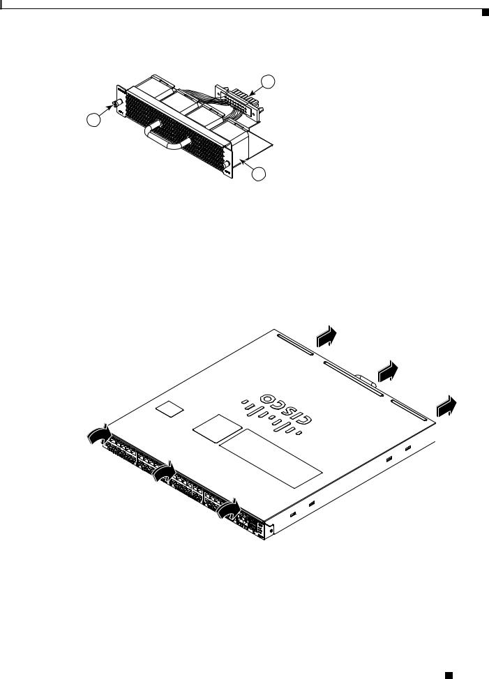
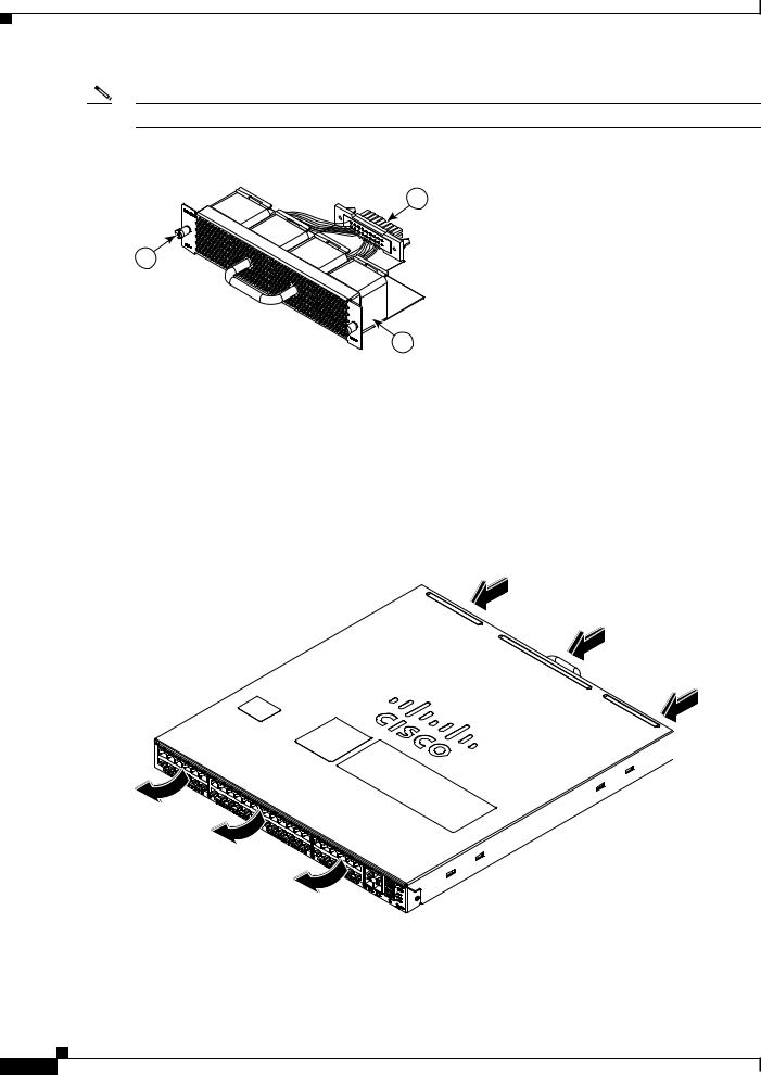
Figure 1-3 Catalyst 4948E Fan Tray
2
1
278085
3
1 |
Backplane connector |
3 |
12 VDC fan (4X). Air is drawn in from the |
|
|
|
front of the chassis and exhausted through the |
|
|
|
rear of the chassis. |
|
|
|
|
2 |
Captive installation screw (2X) |
|
|
|
|
|
|
The fan tray draws in air through vents at the front of the chassis and exhausts it through the rear of the chassis as shown in Figure 1-4.
Figure 1-4 Catalyst 4948E Chassis Airflow
 207440
Catalyst 4948E-F Fan Tray (WS-X4993-F=)
The Catalyst 4948E-F chassis fan tray (WS-X4993-F=) contains four variable-speed, 12 VDC fans. (See Figure 1-5.) The fan tray is mounted in the rear of the chassis between the two power supplies.
Catalyst 4948E and Catalyst 4948E-F Switch Installation Guide
|
OL-21561-02 |
1-9 |
|
|
|
Chapter 1 Product Overview
Fan Tray
Note The WS-X4993-F fan tray is keyed to prevent insertion into the Catalyst 4948E switch chassis.
Figure 1-5 Catalyst 4948E-F Fan Tray
2
1
278085
3
1 |
Backplane connector |
3 |
12 VDC fan (4X). Air is drawn in from the |
|
|
|
rear of the chassis and exhausted through the |
|
|
|
front of the chassis. |
|
|
|
|
2 |
Captive installation screw (2X) |
|
|
|
|
|
|
The fan tray draws in air through vents at the rear of the chassis and exhausts it through the front of the chassis as shown in Figure 1-6.
Figure 1-6 Catalyst 4948E-F Chassis Airflow
 281614
|
Catalyst 4948E and Catalyst 4948E-F Switch Installation Guide |
1-10 |
OL-21561-02 |
Chapter 1 Product Overview
Front Panel LEDs
Front Panel LEDs
A set of LEDs on the chassis front panel provide visual status for the switch. (See Figure 1-7.) Table 1-5 lists the Catalyst 4948E and Catalyst 4948E-F switch chassis front panel LEDs and their meanings.
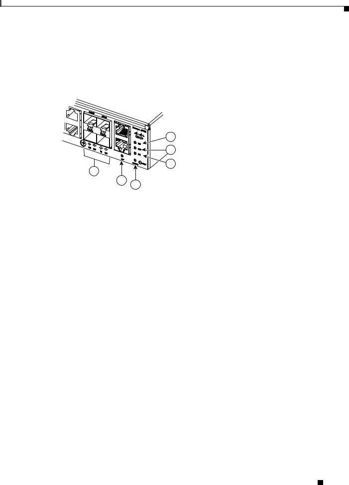
Figure 1-7 Front Panel LEDs
1 |
|
2 |
278086 |
3 |
6
5
4
1 |
PS1 (power supply 1) |
4 |
STATUS |
||
|
|
|
|
|
|
2 |
PS2 (power supply 2) |
5 |
MGT (management port LED) |
||
|
|
|
|
|
|
3 |
FAN (fan tray) |
6 |
LINK (port status). One LED for each uplink |
||
|
|
|
|
and downlink port. |
|
|
|
|
|
|
|
Table 1-5 |
Front Panel LED Descriptions |
|
|
|
|
|
|
|
|
||
LED |
|
State and Meaning |
|||
|
|
|
|
||
STATUS |
|
Green—The system is up and running. |
|||
|
|
|
Red—System fault. |
||
|
|
|
Flashing amber—Power-on self-test (POST) boot |
||
|
|
|
up. |
||
|
|
|
Off—System is not powered up. |
||
|
|
|
|
||
LINK |
|
Green—Link is established. |
|||
48 10/100/1000 downlink port LEDs and 4 |
Amber—Administrative disabled. |
||||
SFP/SFP+ uplink port LEDs |
Off—No link is detected. |
||||
|
|
|
|||
|
|
|
|
||
FAN |
|
Green—Fan tray OK. |
|||
(Fan tray) |
|
Red—One or more fan failures. |
|||
|
|
|
|||
|
|
|
|
||
PS1 |
|
Green—AC-input or DC-input power is OK. |
|||
(Power supply 1)1 |
Red—Power supply fault detected. |
||||
|
|
|
|||
|
|
|
|
||
PS2 |
|
Green—AC-input or DC-input power is OK. |
|||
(Power supply 2)1 |
Red—Power supply fault detected. |
||||
|
|
|
|||
|
|
|
|
|
|
1.There are three additional LEDs mounted on the power supply front panel that provide power supply status. These LEDs are only visible from the back of the chassis. For a description of the LEDs, see the “300 W AC-Input Power Supply (PWR-C49E-300AC-R)” section on page A-1.
Catalyst 4948E and Catalyst 4948E-F Switch Installation Guide
|
OL-21561-02 |
1-11 |
|
|
|

Chapter 1 Product Overview
Front Panel LEDs
|
Catalyst 4948E and Catalyst 4948E-F Switch Installation Guide |
1-12 |
OL-21561-02 |

C H A P T E R 2
Preparing for Installation
Revised: July 2012
Planning a proper location for the switch and the layout of your equipment rack or wiring closet is essential for successful system operation. Equipment placed too close together or inadequately ventilated can cause system overtemperature conditions. In addition, poor equipment placement can make network interface connections inaccessible and difficult to maintain.
This chapter describes how to prepare your site for switch installation and includes these sections:
•Safety, page 2-1
•Site Requirements, page 2-2
•System Grounding, page 2-7
•Power Requirements, page 2-11
•Cabling Requirements, page 2-13
•Site Preparation Checklist, page 2-13
Tip For additional information about the Cisco Catalyst 4948E or the Catalyst 4948E-F switch (including configuration examples and troubleshooting information), see the documents listed on this page:
http://www.cisco.com/en/US/products/ps6021/tsd_products_support_series_home.html
Safety
Safety warnings appear throughout this publication in procedures that may harm you if performed incorrectly. A warning symbol precedes each warning statement. The warnings below are general warnings that are applicable to the entire publication.
Warning Only trained and qualified personnel should be allowed to install, replace, or service this equipment.
Statement 1030
Catalyst 4948E and Catalyst 4948E-F Switch Installation Guide
|
OL-21561-02 |
2-1 |
|
|
|

Chapter 2 Preparing for Installation
Site Requirements
Warning This unit is intended for installation in restricted access areas. A restricted access area can be accessed only through the use of a special tool, lock and key, or other means of security.
Statement 1017
Warning Voltages that present a shock hazard may exist on Power over Ethernet (PoE) circuits if interconnections are made using uninsulated exposed metal contacts, conductors, or terminals. Avoid using such interconnection methods, unless the exposed metal parts are located within a restricted access location and users and service people who are authorized within the restricted access location are made aware of the hazard. A restricted access area can be accessed only through the use of a special tool, lock and key or other means of security. Statement 1072
Site Requirements
These following sections describe some of the basic site requirements that you should be aware of as you prepare to install your Catalyst 4948E or Catalyst 4948E-F switch:
•Rack-Mounting Guidelines, page 2-2
•Temperature, page 2-3
•Air Flow, page 2-4
•Humidity, page 2-5
•Altitude, page 2-5
•Dust and Particulates, page 2-5
•Corrosion, page 2-6
•Electromagnetic and Radio Frequency Interference, page 2-6
•Shock and Vibration, page 2-7
•Maintaining Safety with Electricity, page 2-9
•Preventing Electrostatic Discharge Damage, page 2-10
Rack-Mounting Guidelines
A rack-mount kit (69-2037-xx) is included in the accessory kit for mounting the switch in a standard 19-inch (48.3 cm) equipment rack. This rack-mount kit is not suitable for use in the following situations:
•Racks with obstructions (such as power strips) that could impair access to the switch Before rack-mounting the switch, ensure the following:
•The equipment rack is the proper size.
–The width of the rack, between the two front-mounting strips or rails, must be 17.75 inches (45.09 cm).
–The depth of the rack, between the frontand rear-mounting strips, must be at least 19.25 inches (48.9 cm) but not more than 32.5 inches (82.5 cm).
–The rack must have sufficient vertical clearance to insert the chassis. The chassis height is 1 U (1.75 inches (4.45 cm)).
Catalyst 4948E and Catalyst 4948E-F Switch Installation Guide
2-2 |
OL-21561-02 |
|
|
Loading...