


 Loading...
White Paper
Cisco Catalyst 6500 Architecture
This paper will provide an insight into the architecture of the Cisco® Catalyst® 6500 family,
including supervisor engines, line cards, chassis, and other components.
Cisco Catalyst 6500 Chassis
The Cisco Catalyst 6500 is a modular chassis family supporting a range of line-card options for all customer network deployments. Its performance scales up to 400Mpps, providing one of the highest performing switch products on the market today. It supports a range of chassis options delivering from 3 to 13 slots. All chassis support redundant supervisor engines as well as redundant power supplies. The chassis options are shown in Figure 1.
Figure 1. Cisco Catalyst 6500 Chassis Family
The Cisco Catalyst 6500 chassis family includes the following:
●Cisco Catalyst 6503 Switch: Three-slot chassis supporting redundant power supplies, redundant supervisor engines, and slots for up to two (2) line cards. NEBS L3 compliant.
●Cisco Catalyst 6506 Switch: Six slot chassis supporting redundant power supplies, redundant supervisor engines, and slots for up to five (5) line cards. NEBS L3 compliant.
●Cisco Catalyst 6509 Switch: Nine slot chassis supporting redundant power supplies, redundant supervisor engines, and slots for up to eight (8) line cards. NEBS L3 compliant.
●Cisco Catalyst 6509-NEB Switch: NEBS based nine slot chassis supporting redundant power supplies, redundant supervisor engines, and slots for up to eight (8) line cards. This chassis also supports front to back airflow and is NEBS L3 compliant.
All contents are Copyright © 1992–2007 Cisco Systems, Inc. All rights reserved. This document is Cisco Public Information. |
Page 1 of 27 |

White Paper
●Cisco Catalyst 6509-NEB-A Switch: NEBS based nine slot chassis supporting redundant power supplies, redundant supervisor engines, and slots for up to eight (8) line cards. This NEBS based chassis differs from the first Cisco Catalyst 6509-NEB in that it can support the new Cisco Catalyst 6500 Series Supervisor Engine 720 without any upgrades to the chassis.
●Cisco Catalyst 6513 Switch: Thirteen slot chassis supporting redundant power supplies, redundant supervisor engines, and slots for up to twelve (12) line cards. This chassis requires the Supervisor Engine 2 as the minimum version of installed supervisor.
NEBS L3 compliant.
Cisco has also recently introduced a new “E” series chassis that is designed to support a larger power draw over the backplane and also drive higher power loads to each line-card slot. In all, four new “E” series chassis have been announced:
●Cisco Catalyst 6503-E Switch: Three slot chassis supporting redundant power supplies, redundant supervisor engines, and slots for up to two (2) line cards. NEBS L3 compliant. This chassis increases available power from 50A@42V (~2500W) to 80A@42V (~4000W).
●Cisco Catalyst 6504-E Switch: Four slot chassis supporting redundant power supplies, redundant supervisor engines, and slots for up to three (3) line cards. NEBS L3 compliant. This chassis increases available power from 50A@42V (~2500W) to 80A@42V (~4000W).
●Cisco Catalyst 6506-E Switch: Six slot chassis supporting redundant power supplies, redundant supervisor engines, and slots for up to five (5) line cards. NEBS L3 compliant. This chassis increases available power from 90A@42V (~4000W) to 350A@42V (~12000W).
●Cisco Catalyst 6509-E Switch: Nine slot chassis supporting redundant power supplies, redundant supervisor engines, and slots for up to eight (8) line cards. NEBS L3 compliant. This chassis increases available power from 90A@42V (~4000W)to 350A@42V (~12000W).
Cisco Catalyst 6500 Backplane
The Cisco Catalyst 6500 incorporates two backplanes. From its initial release in 1999, the Cisco Catalyst 6500 chassis has supported a 32-Gbps shared switching bus, a proven architecture for interconnecting line cards within the chassis. The Cisco Catalyst 6500 chassis also includes a second backplane that allows line cards to connect over a high-speed switching path into a crossbar switching fabric. The crossbar switching fabric provides a set of discrete and unique paths for each line card to both transmit data into and receive data from the crossbar switching fabric. The first generation switching fabric was delivered by the switch fabric modules (WS- C6500-SFM and WS-C6500-SFM2), each providing a total switching capacity of 256 Gbps. More recently, with the introduction of the Supervisor Engine 720, the crossbar switch fabric has been integrated into the Supervisor Engine 720 baseboard itself, eliminating the need for a standalone switch fabric module. The capacity of the new integrated crossbar switch fabric on the Supervisor Engine 720 has been increased from 256 Gbps to 720 Gbps. The Supervisor Engine 720-3B and Supervisor Engine 720-3BXL also maintain the same fabric capacity size of 720 Gbps.
Depending on the Cisco Catalyst 6500 chassis, the crossbar switching fabric maps out a series of fabric channels (otherwise known as paths into the crossbar) to each line-card slot in a slightly different layout. Each chassis fabric layout is detailed in Table 1.
Table 1. Chassis Slot Options
All contents are Copyright © 1992–2007 Cisco Systems, Inc. All rights reserved. This document is Cisco Public Information. |
Page 2 of 27 |
White Paper
Chassis |
Supervisor Engine |
Classic Line- |
Single Fabric |
Dual Fabric |
|
32/ Supervisor |
Card Slots |
Connected Line |
Connected Line |
|
Engine 720 Slots |
|
Cards |
Cards |
Cisco Catalyst 6503 |
1 and 2 |
2 and 3 |
2 and 3 |
WS-X67XX |
|
|
|
|
line cards not |
|
|
|
|
supported |
|
|
|
|
|
Cisco Catalyst 6503-E |
1 and 2 |
2 and 3 |
2 and 3 |
2 and 3 |
|
|
|
|
|
Cisco Catalyst 6504-E |
1 and 2 |
2 thru 4 |
2 thru 4 |
2 thru 4 |
|
|
|
|
|
Cisco Catalyst 6506 |
5 and 6 |
1 through 6 |
1 through 6 |
1 through 6 |
|
|
|
|
|
Cisco Catalyst 6506-E |
5 and 6 |
1 through 6 |
1 through 6 |
1 through 6 |
|
|
|
|
|
Cisco Catalyst 6509 |
5 and 6 |
1 through 9 |
1 through 9 |
1 through 9 |
|
|
|
|
|
Cisco Catalyst 6509-E |
5 and 6 |
1 through 9 |
1 through 9 |
1 through 9 |
|
|
|
|
|
Cisco Catalyst 6509-NEB |
5 and 6 |
1 through 9 |
1 through 9 |
1 through 9 |
|
|
|
|
|
Cisco Catalyst 6509-NEB-A |
5 and 6 |
1 through 9 |
1 through 9 |
1 through 9 |
|
|
|
|
|
Cisco Catalyst 6513 |
7 and 8 |
1 through 13 |
1 through 13 |
9 through 13 |
|
|
|
|
|
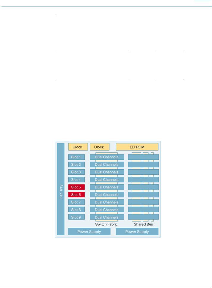
In all but the thirteen slot chassis, each line-card slot has two channels in and out of the switching fabric. The thirteen slot chassis has one fabric channel to each slot in slots 1 through 8 and two fabric channels to each slot in slots 9 through 13. The crossbar switching fabric allows each line card to forward and receive data to every other line card over a unique set of transmission paths.
Figure 2 shows the backplane and line-card connectors for a Cisco Catalyst 6509-E chassis.
Figure 2. Cisco Catalyst 6509-E Backplane
All contents are Copyright © 1992–2007 Cisco Systems, Inc. All rights reserved. This document is Cisco Public Information. |
Page 3 of 27 |

White Paper
Cisco Catalyst 6500 Fans
The Cisco Catalyst 6500 supports two generations of fans. A new set of high-speed fans was introduced with the announcement of the Supervisor Engine 720. New high-speed fans have been designed for each Cisco Catalyst 6500 chassis, and their primary purpose is to provide additional cooling for new generation line cards that draw more power and generate more heat.
If a Supervisor Engine 32, 720, 720-3B, or 720-3BXL is installed in the chassis, then the new highspeed FAN assemblies must be used. The FAN2 assemblies are used with the standard chassis, and the E-Fan is used with the new E series chassis. These high-speed fans can also be used with previous generations of the supervisor engine (1, 1A and 2). (See Figure 3 and Table 2.)
Figure 3. Cisco Catalyst 6500 Fans
Table 2. |
Fan Options |
|
|
|
|
|
|
Chassis |
|
Original FAN (FAN1) |
High-Speed FAN (FAN2) |
|
|
|
|
Cisco Catalyst 6503 |
FAN-MOD-3 |
Fan-MOD-3HS |
|
|
|
|
|
Cisco Catalyst 6503-E |
N/A |
WS-C6503-E-FAN |
|
|
|
|
|
Cisco Catalyst 6504-E |
N/A |
WS-C6504-E-FAN |
|
|
|
|
|
Cisco Catalyst 6506 |
WS-C6K-6SLOT-FAN |
WS-C6K-6SLOT-FAN2 |
|
|
|
|
|
Cisco Catalyst 6506-E |
N/A |
WS-C6506-E-FAN |
|
|
|
|
|
Cisco Catalyst 6509 |
WS-C6K-9SLOT-FAN |
WS-C6K-9SLOT-FAN2 |
|
|
|
|
|
Cisco Catalyst 6509-E |
N/A |
WS-C6509-E-FAN |
|
|
|
|
|
Cisco Catalyst 6509-NEB |
WS-C6509-NEB-FAN |
WS-C6509-NEB-FAN2 |
|
|
|
|
|
Cisco Catalyst 6509-NEB-A |
N/A |
FAN-MOD-09 |
|
|
|
|
|
Cisco Catalyst 6513 |
WS-C6K-13SLOT-FAN |
WS-C6K-13SLOT-FAN2 |
|
|
|
|
|
Cisco Catalyst 6500 Power Supplies
The Cisco Catalyst 6500 supports a range of AC and DC power supplies to suit a diverse range of customer requirements. The power supplies supported are listed in Tables 3 and 4.
Table 3. |
Cisco Catalyst 6500 AC and DC Power Supplies |
|
|
|
||||
|
|
|
|
|
|
|
|
|
|
Power Supply (Part Number) |
Cisco |
Cisco |
Cisco |
Cisco |
Cisco |
Cisco |
|
|
|
|
Catalyst |
Catalyst |
Catalyst |
Catalyst |
Catalyst |
Catalyst |
|
|
|
6503 |
6506 |
6509 |
6509-NEB |
6509-NEB-A |
6513 |
|
|
|
|
|
|
|
|
|
|
950WAC (PWR 950-AC) |
X |
|
|
|
|
|
|
|
|
|
|
|
|
|
|
|
|
950WDC (PWR 950-DC) |
X |
|
|
|
|
|
|
|
|
|
|
|
|
|
|
|
All contents are Copyright © 1992–2007 Cisco Systems, Inc. All rights reserved. This document is Cisco Public Information. |
Page 4 of 27 |

White Paper
Power Supply (Part Number) |
Cisco |
Cisco |
Cisco |
Cisco |
Cisco |
Cisco |
|
Catalyst |
Catalyst |
Catalyst |
Catalyst |
Catalyst |
Catalyst |
|
6503 |
6506 |
6509 |
6509-NEB |
6509-NEB-A |
6513 |
1000WAC (WS CAC-1000W) |
|
X |
X |
X |
|
|
|
|
|
|
|
|
|
1300WAC (WS CAC-1300W) |
|
X |
X |
X |
|
|
|
|
|
|
|
|
|
1300WDC (WS CDC-1300W) |
|
X |
X |
X |
|
|
|
|
|
|
|
|
|
1400WAC (PWR 1400W-AC) |
X |
|
|
|
|
|
|
|
|
|
|
|
|
2500WAC (WS CAC-2500W) |
|
X |
X |
X |
X |
X |
|
|
|
|
|
|
|
2500WDC (WS CDC-2500W) |
|
X |
X |
X |
X |
X |
|
|
|
|
|
|
|
3000WAC (WS CAC-3000W) |
|
X |
X |
X |
X |
X |
|
|
|
|
|
|
|
4000WAC (WS CAC-4000W) |
|
X |
X |
X |
X |
X |
|
|
|
|
|
|
|
4000WDC (PWR 4000DC) |
|
X |
X |
X |
X |
X |
|
|
|
|
|
|
|
6000WAC (WS CAC-6000W) |
|
X |
X |
X |
X |
X |
|
|
|
|
|
|
|
8700WAC (WS CAC-8700W-E) |
|
X |
X |
|
X |
X |
|
|
|
|
|
|
|
Table 4. |
Cisco Catalyst 6500 E Series AC and DC Power Supplies |
|
|
||
|
|
|
|
|
|
Power Supply (Part Number) |
Cisco Catalyst |
Cisco Catalyst |
Cisco Catalyst |
Cisco Catalyst |
|
|
|
6503-E |
6504-E |
6506-E |
6509-E |
|
|
|
|
|
|
950WAC (PWR-950-AC) |
X |
|
|
|
|
|
|
|
|
|
|
950WDC (PWR-950-DC) |
X |
|
|
|
|
|
|
|
|
|
|
1400WAC (PWR-1400W-AC) |
X |
|
|
|
|
|
|
|
|
|
|
2500WAC (WS-CAC-2500W) |
|
|
X |
X |
|
|
|
|
|
|
|
2500WDC (WS-CDC-2500W) |
|
|
X |
X |
|
|
|
|
|
|
|
2700WAC (PWR-2700W-AC) |
|
X |
|
|
|
|
|
|
|
|
|
3000WAC (WS-CAC-3000W) |
|
|
X |
X |
|
|
|
|
|
|
|
4000WAC (WS-CAC-4000W) |
|
|
X |
X |
|
|
|
|
|
|
|
4000WDC (PWR-4000DC) |
|
|
X |
X |
|
|
|
|
|
|
|
6000WAC (WS-CAC-6000W) |
|
|
X |
X |
|
|
|
|
|
|
|
8700WAC (WS-CAC-8700W-E) |
|
|
X |
X |
|
|
|
|
|
|
|
Each of the power supplies provides a different set of operating characteristics. These are summarized in Table 5.
Table 5. |
Cisco Catalyst 6500 Power Supply Characteristics |
|
|
||||
|
|
|
|
|
|
||
Power Supply |
Part Number |
AC Operation |
|
DC Operation |
Current Output |
||
|
|
|
|
|
|
|
|
950WAC |
|
PWR-950-AC |
950W @ 110-220VAC |
|
|
21.09A |
|
|
|
|
|
|
|
|
|
950WDC |
|
PWR-950-DC |
|
|
|
950W @ -48 to -60 |
21.09A |
|
|
|
|
|
|
VDC |
|
|
|
|
|
|
|
|
|
1000WAC |
|
WS-CAC-1000W |
1000W |
@ 110-220VAC |
|
|
20.3A |
|
|
|
|
|
|
|
|
1300WAC |
|
WS-CAC-1300W |
1300W |
@ 110-220VAC |
|
|
27.46A |
|
|
|
|
|
|
|
|
1300WDC |
|
WS-CDC-1300W |
|
|
|
1300W @ -48 to -60 |
27.46A |
|
|
|
|
|
|
VDC |
|
|
|
|
|
|
|
|
|
1400WAC |
|
PWR-1400W-AC |
1400W |
@ 110-220VAC |
|
|
32.62A |
|
|
|
|
|
|
|
|
2500WAC |
|
WS-CAC-2500W |
2500W |
@ 220VAC |
|
|
55.5A for 220VAC |
|
|
|
1300W |
@ 110VAC |
|
|
27.46A for 110VAC |
|
|
|
|
|
|
|
|
2500WDC |
|
WS-CDC-2500W |
|
|
|
2500W @ -48VDC |
55.5A |
|
|
|
|
|
|
2500W @ -60 VDC |
|
|
|
|
|
|
|
|
|
2700WAC |
|
PWR-2700W-AC |
1350W@110V |
|
|
63.55A |
|
|
|
|
2700W@220V |
|
|
|
|
|
|
|
|
|
|
|
|
All contents are Copyright © 1992–2007 Cisco Systems, Inc. All rights reserved. This document is Cisco Public Information. |
Page 5 of 27 |

White Paper
Power Supply |
Part Number |
AC Operation |
DC Operation |
Current Output |
|
|
|
|
|
|
|
3000WAC |
WS-CAC-3000W |
3000W @ 220VAC |
|
65.11 for 220VAC |
|
|
|
1450W |
@ 110VAC |
|
28.21A for 110VAC |
|
|
|
|
|
|
4000WAC |
WS-CAC-4000W |
4000W @ 220VAC |
|
91.2A |
|
|
|
30A circuit required |
|
|
|
|
|
|
|
|
|
4000WDC |
PWR-4000-DC |
|
|
1300W @ -48 to -60 |
91.2A |
|
|
|
|
VDC |
|
|
|
|
|
|
|
6000WAC |
WS-CAC-6000W |
6000W @ 2 x 220VAC |
|
|
|
|
|
3000W |
@ 1 x 220VAC |
|
|
|
|
3000W |
@ 2 x 110VAC |
|
|
|
|
|
|
|
|
8700WAC |
WS-CAC- |
8700W @ 3 x 220VAC |
|
|
|
|
8700W-E |
4200W |
@ 3 x 110VAC |
|
|
|
|
|
|
||
|
|
6000W |
@ 2 x 220VAC |
|
|
|
|
2800W |
@ 1 x 220VAC |
|
|
|
|
2800W |
@ 2 x 110VAC |
|
|
|
|
|
|
|
|
As noted in the table above, the 2500WAC, 2700WAC, 3000WAC, 6000WAC and 8700WAC power supplies do not deliver full power in an environment running on 110VAC. The 2500W power supply will deliver 1300W at 110VAC, the 2700W will deliver 1350W at 110VAC, the 3000W will deliver 1450W at 110VAC,the 6000W will deliver 3000W with 2 x 110VAC circuits and the 8700W will deliver 4200W with 3 x 110VAC circuits. It is also worth noting that current output is defined as the amount of power made available by the power supplies to the chassis components.
Cisco Catalyst 6500 Supervisor Engines
The Cisco Catalyst 6500 supervisor engine is the primary module where the switch software is loaded and all centralized control and data plane processes are performed. Control plane functions refer to processes that are run in software, whereas data plane functions refer to processes that are run in hardware.
The Supervisor Engine 32 supports a connection to the 32-Gbps shared bus and provides forwarding rates up to 15Mpps. There is no support for a switch fabric in any form with the Supervisor Engine 32. The new Supervisor Engine 720, 720-3B, and 720-3BXL integrate the 720-Gbps crossbar switch fabric onto the supervisor module itself and support a connection into the 32-Gbps bus and a single 20-Gbps connection into the onboard crossbar switch fabric. All Supervisor Engine 720 options support centralized forwarding rates up to 30Mpps and distributed forwarding rates up to 400Mpps.
Supervisor Engine 32
The Supervisor Engine 32 is the most recent addition to the Cisco Catalyst 6500 supervisor engine family. This supervisor engine provides an integrated PFC3B and MSFC2a by default. The PFC3B provides hardware support for security and quality of service (QoS) based access control lists (ACLs). QoS services supported on the PFC3B include ingress traffic policing as well as classification of incoming data allowing the rewrite of class of service (CoS) bits in the Ethernet header and type of service priority bits in the IPV4 header. Performance for these features is supported at a rate of up to 15Mpps.
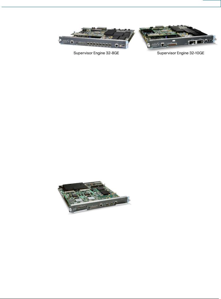
There are two versions of the Supervisor Engine 32 (Figure 4), one with 8 front Gigabit Ethernet Small Form-Factor Pluggable (SFP) ports and the other with 2 x 10 Gigabit Ethernet front ports. Both of these supervisor engines also have an additional 10/100/1000TX front port. Two USB ports are also present on the front panel, one a type “A” and the other a type “B” USB port.
All contents are Copyright © 1992–2007 Cisco Systems, Inc. All rights reserved. This document is Cisco Public Information. |
Page 6 of 27 |
White Paper
Figure 4. Supervisor Engine 32-8GE and Supervisor Engine 32-10GE
Cisco Express Forwarding is the forwarding architecture implemented in the Supervisor Engine 32 hardware. As with the Supervisor Engine 720, it also implements hardware registers and control plane policing (CoPP) to limit the effect of denial of service attacks on the control plane. It comes standard with 256MB of Bootflash on the switch processor (SP) side (which can be upgraded to 512MB) and 64MB of Bootflash on the route processor (RP) side. Memory (DRAM) size is 256MB for both the RP and SP and NVRAM is 2MB.
Supervisor Engine 720
The Supervisor Engine 720 was introduced in 2003 and integrates the crossbar switch fabric, Policy Feature Card 3 (PFC3), and Multilayer Switch Feature Card 3 (MSFC3) into the one supervisor module. The PFC3 and MSFC3 are no longer optional.
The crossbar switching fabric on the Supervisor Engine 720 (Figure 5) increases backplane capacity of the crossbar switch fabric from 256 Gbps to 720 Gbps. The crossbar switching fabric supports connections to both the earlier fabric line cards, at 8 Gbps per fabric channel, and the newer fabric line cards, at 20 Gbps per fabric channel. The Supervisor Engine720 also supports classic line cards, thus providing total backward compatibility for all line-card generations. This dual clocking capability preserves customer investment in previous line cards supporting connections into the crossbar switch fabric.
Figure 5. Cisco Catalyst 6500 Supervisor Engine 720
Utilizing the new higher performance line cards with distributed forwarding allows a Supervisor Engine 720 to scale switch performance to 400Mpps.
The Supervisor Engine 720 utilizes the Cisco Express Forwarding architecture to forward packets. Support for up to 30Mpps of Layer 2 and 3 centralized switching of IP traffic is supported. Unlike the earlier PFC1 and PFC2, IPX switching in hardware is not supported on the Supervisor Engine 720 PFC3. The Supervisor Engine 720, however, does still support IPX forwarding in software.
The Supervisor Engine 720 is based on a 600 MHz CPU for the switch processor (SP) and a 600 MHz CPU for the route processor (RP). This supervisor will support up to 1GB of DRAM for the SP and up to 1Gb DRAM for the RP. The default SP bootflash is 512MB, the default RP bootflash is 64 MB and the NVRAM size is 2MB.
Supervisor Engine 720-3B
All contents are Copyright © 1992–2007 Cisco Systems, Inc. All rights reserved. This document is Cisco Public Information. |
Page 7 of 27 |
White Paper
The Supervisor Engine 720-3B is the most recent addition to the Supervisor Engine 720 family. Architecturally it is the same as the original Supervisor Engine 720 in terms of the switch fabric used and the backplane connections offered. It incorporates a new PFC3B, which increases the functionality of the supervisor engine over its predecessor. It differs from the original Supervisor Engine 720 mainly in functionality. Some of the features that differentiate it from the earlier Supervisor Engine 720 include:
●MPLS support in hardware
●Support for EoMPLS
●Support for Security ACL hit counters
●Multipath URPF check now performed in hardware
●Increased has efficiency (from 50 percent to 90 percent) for storing NetFlow entries in the NetFlow table
●Increased support for ACL labels from 512 to 4096
●QoS policies can now be applied on tunnel interfaces
●Layer 2 ACLs can be applied to IPV4 traffic
●Support for matching on CoS and VLAN in ACLs is now supported
●Support for up to 256K multicast routes in sparse mode
Supervisor Engine 720-3BXL
The Supervisor Engine 720-3BXL was introduced early in calendar year 2004. It is functionally identical to the Supervisor Engine 720-3B, but differs in its capacity for supporting routes and NetFlow entries. Up to 1 million routes can be stored in its forwarding tables and up to 256K NetFlow entries can be stored in the NetFlow tables.
Multilayer Switch Feature Card (MSFC)
The control plane functions in the Cisco Catalyst 6500 are processed by the MSFC and include handling Layer 3 routing protocols, maintaining the routing table, some access control, flow initiation, and other services not found in hardware. Performance of the control plane is dependent on the type and number of processes running on the MSFC. The MSFC3 can support forwarding rates up to 500Kpps.
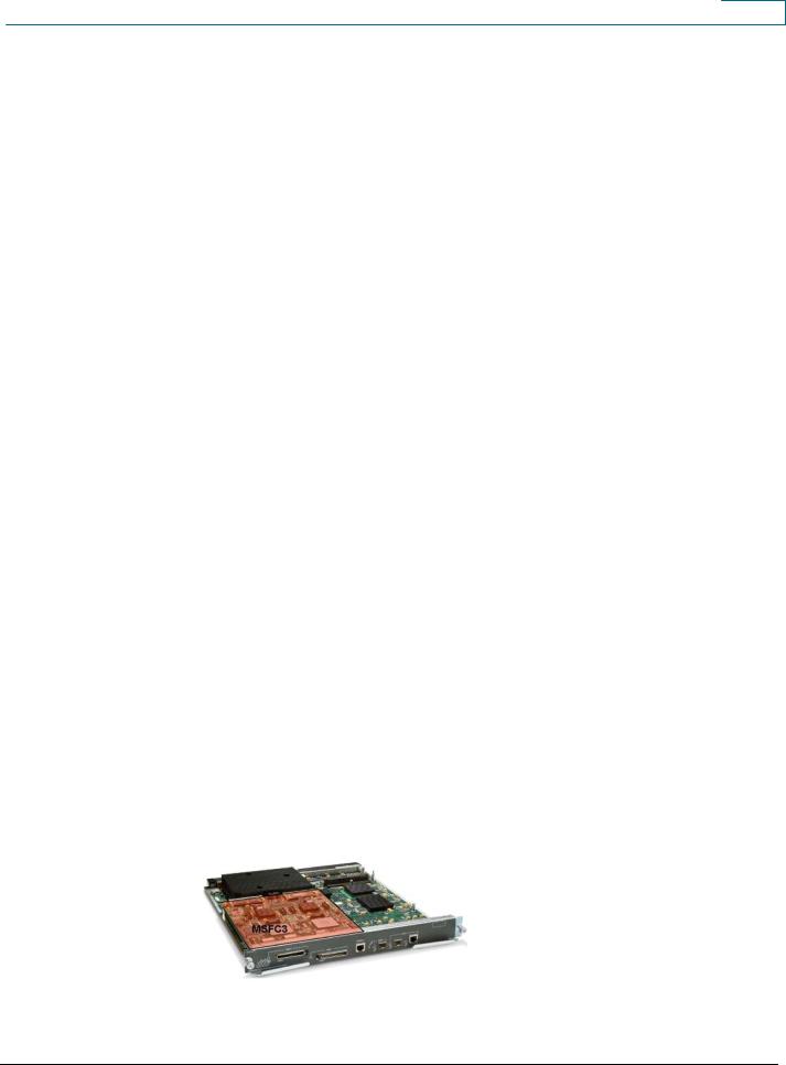
The MSFC3 is an integrated component on the Supervisor Engine 720, Supervisor Engine 720-3B, and Supervisor Engine 720-3BXL. It is integrated onto all of the Supervisor Engine 720 options along with the PFC3 and crossbar switch fabric. The MSFC3 is shown on a Supervisor Engine 720 in Figure 6.
Figure 6. MSFC3 on a Supervisor Engine 720
On the MSFC daughter card, the route processor (RP) is located on the MSFC itself. The RP is responsible for a number of processes, including running the Layer 3 routing protocols,
All contents are Copyright © 1992–2007 Cisco Systems, Inc. All rights reserved. This document is Cisco Public Information. |
Page 8 of 27 |

White Paper
performing address resolution, running ICMP, managing the virtual interfaces (that is, switched virtual interfaces), and the Cisco IOS® Software configuration. The SP is primarily responsible for running the Layer 2 protocols like spanning tree, VLAN Trunking protocol, Cisco Discovery Protocol, and so on as well as programming the FIB tables onto the PFC.
While the multilayer switch feature card maintains the routing tables, it does not actively participate in the forwarding of packets. The MSFC3 still participates in communicating with routing peers to determine the network topology and maintain the routing tables. From the routing tables, the MSFC3 will create a Cisco Express Forwarding table (also known as a Forwarding Information Base—or FIB table) and push this down to the PFC and any DFCs present in the chassis.
The memory configurations across the different generations of supervisor (and MSFC) are detailed in Table 6.
Table 6. |
Supervisor Engine and MSFC Memory Facts |
|
|
|
|||
|
|
|
|
|
|
|
|
Component |
|
Supervisor |
Supervisor |
|
Supervisor |
Supervisor |
Supervisor |
|
|
Engine 32- |
Engine 32- |
|
Engine 720 |
Engine 720-3B |
Engine 720- |
|
|
8GE |
10GE |
|
|
|
3BXL |
|
|
|
|
|
|
|
|
SDRAM |
|
|
|
|
|
|
|
|
|
|
|
|
|
|
|
Default |
|
SP: |
SP: |
|
SP: |
SP: |
SP: |
|
|
256MB/1GB |
256MB/1GB |
|
512MB/1GB |
512MB/1GB |
512MB/1GB |
|
|
|
|
|
|
|
|
Maximum |
|
RP: |
RP: |
|
RP: |
RP: |
RP: |
|
|
256MB/1GB |
256MB/1GB |
|
512MB/1GB |
512MB/1GB |
512MB/1GB |
|
|
|
|
|
|
|
|
Bootflash |
|
RP: 64MB |
RP: 64MB |
|
RP: 64MB |
RP: 64MB |
RP: 64MB |
|
|
SP: 256MB |
SP: 256MB |
|
SP: 512MB* |
SP: 512MB* |
SP: 512MB* |
|
|
|
|
|
|
|
|
NVRAM |
|
SP: 2MB |
SP: 2MB |
|
SP: 2MB |
SP: 2MB |
SP: 2MB |
|
|
RP: 2MB |
RP: 2MB |
|
RP: 2MB |
RP: 2MB |
RP: 2MB |
|
|
|
|
|
|
|
|
* Note that 512MB of DRAM is standard on the Sup720 when ordering IOS 12.2(18)SXE or later
Policy Feature Card
Complementing the MSFC is the policy feature card (PFC). The PFC is a daughter card that sits on the supervisor base board and contains the ASICs that are used to accelerate Layer 2 and Layer 3 switching, store and process QoS and security ACLs, and maintain NetFlow statistics.
The Policy Feature Card 3 (PFC3) is a standard inclusion with the Supervisor Engine 720 and provides centralized forwarding performance up to 30Mpps. It contains a Layer 2 and a Layer 3 forwarding engine. The Layer 2 engine is responsible for:
●Layer 2 MAC address lookups into the Layer 2 CAM table.
●Looking into the packet headers to determine if this switching operation will be a Layer 2 or a Layer 3 operation. If it is going to be a Layer 3 operation, then it will hand off the packet to the Layer 3 engine for further processing.
The Layer 3 Engine is responsible for:
●NetFlow Statistics collection.
●Hardware based forwarding of IPv4, IPv6 and MPLS tagged packets
●QoS mechanism for ACL classification, marking of packets, and policing (rate limiting).
●Security mechanism for validating ACL rules against incoming packets.
●Maintaining Adjacency entries and statistics
●Maintaining Security ACL counters
All contents are Copyright © 1992–2007 Cisco Systems, Inc. All rights reserved. This document is Cisco Public Information. |
Page 9 of 27 |
Loading...