


 Loading...
Cisco Video Surveillance 5010/5011 Indoor Fixed HD IP Dome Camera User Guide
Americas Headquarters
Cisco Systems, Inc. 170 West Tasman Drive
San Jose, CA 95134-1706 USA http://www.cisco.com Tel: 408 526-4000
800 553-NETS (6387) Fax: 408 527-0883
Text Part Number: OL-22669-02
THE SPECIFICATIONS AND INFORMATION REGARDING THE PRODUCTS IN THIS MANUAL ARE SUBJECT TO CHANGE WITHOUT NOTICE. ALL STATEMENTS, INFORMATION, AND RECOMMENDATIONS IN THIS MANUAL ARE BELIEVED TO BE ACCURATE BUT ARE PRESENTED WITHOUT WARRANTY OF ANY KIND, EXPRESS OR IMPLIED. USERS MUST TAKE FULL RESPONSIBILITY FOR THEIR APPLICATION OF ANY PRODUCTS.
THE SOFTWARE LICENSE AND LIMITED WARRANTY FOR THE ACCOMPANYING PRODUCT ARE SET FORTH IN THE INFORMATION PACKET THAT SHIPPED WITH THE PRODUCT AND ARE INCORPORATED HEREIN BY THIS REFERENCE. IF YOU ARE UNABLE TO LOCATE THE SOFTWARE LICENSE OR LIMITED WARRANTY, CONTACT YOUR CISCO REPRESENTATIVE FOR A COPY.
The following information is for FCC compliance of Class A devices: This equipment has been tested and found to comply with the limits for a Class A digital device, pursuant to part 15 of the FCC rules. These limits are designed to provide reasonable protection against harmful interference when the equipment is operated in a commercial environment. This equipment generates, uses, and can radiate radio-frequency energy and, if not installed and used in accordance with the instruction manual, may cause harmful interference to radio communications. Operation of this equipment in a residential area is likely to cause harmful interference, in which case users will be required to correct the interference at their own expense.
The following information is for FCC compliance of Class B devices: This equipment has been tested and found to comply with the limits for a Class B digital device, pursuant to part 15 of the FCC rules. These limits are designed to provide reasonable protection against harmful interference in a residential installation. This equipment generates, uses and can radiate radio frequency energy and, if not installed and used in accordance with the instructions, may cause harmful interference to radio communications.
However, there is no guarantee that interference will not occur in a particular installation. If the equipment causes interference to radio or television reception, which can be determined by turning the equipment off and on, users are encouraged to try to correct the interference by using one or more of the following measures:
•Reorient or relocate the receiving antenna.
•Increase the separation between the equipment and receiver.
•Connect the equipment into an outlet on a circuit different from that to which the receiver is connected.
•Consult the dealer or an experienced radio/TV technician for help.
Modifications to this product not authorized by Cisco could void the FCC approval and negate your authority to operate the product.
The Cisco implementation of TCP header compression is an adaptation of a program developed by the University of California, Berkeley (UCB) as part of UCB’s public domain version of the UNIX operating system. All rights reserved. Copyright © 1981, Regents of the University of California.
NOTWITHSTANDING ANY OTHER WARRANTY HEREIN, ALL DOCUMENT FILES AND SOFTWARE OF THESE SUPPLIERS ARE PROVIDED “AS IS” WITH ALL FAULTS. CISCO AND THE ABOVE-NAMED SUPPLIERS DISCLAIM ALL WARRANTIES, EXPRESSED OR IMPLIED, INCLUDING, WITHOUT LIMITATION, THOSE OF MERCHANTABILITY, FITNESS FOR A PARTICULAR PURPOSE AND NONINFRINGEMENT OR ARISING FROM A COURSE OF DEALING, USAGE, OR TRADE PRACTICE.
IN NO EVENT SHALL CISCO OR ITS SUPPLIERS BE LIABLE FOR ANY INDIRECT, SPECIAL, CONSEQUENTIAL, OR INCIDENTAL DAMAGES, INCLUDING, WITHOUT LIMITATION, LOST PROFITS OR LOSS OR DAMAGE TO DATA ARISING OUT OF THE USE OR INABILITY TO USE THIS MANUAL, EVEN IF CISCO OR ITS SUPPLIERS HAVE BEEN ADVISED OF THE POSSIBILITY OF SUCH DAMAGES.
Cisco and the Cisco Logo are trademarks of Cisco Systems, Inc. and/or its affiliates in the U.S. and other countries. A listing of Cisco's trademarks can be found at www.cisco.com/go/trademarks. Third party trademarks mentioned are the property of their respective owners. The use of the word partner does not imply a partnership relationship between Cisco and any other company. (1005R)
Any Internet Protocol (IP) addresses and phone numbers used in this document are not intended to be actual addresses and phone numbers. Any examples, command display output, network topology diagrams, and other figures included in the document are shown for illustrative purposes only. Any use of actual IP addresses or phone numbers in illustrative content is unintentional and coincidental.
Cisco Video Surveillance 5010/5011 Indoor Fixed HD IP Dome Camera User Guide
© 2010, 2011 Cisco Systems, Inc. All rights reserved.

|
|
|
|
|
|
|
|
|
C O N T E N T S |
|||
|
|
|
Preface vii |
|
|
|
|
|
|
|
|
|
|
|
Introduction |
|
|
|
|
|
|
|
|
|
|
C H A P T E R |
1 |
1-1 |
|
|
|
|
|
|
|
|
||
|
|
|
Models |
1-1 |
|
|
|
|
|
|
|
|
|
|
|
Getting Started |
1-1 |
|
|
|
|
|
|
||
|
|
|
Parts List |
1-2 |
|
|
|
|
|
|
|
|
|
|
|
Product Overview |
1-2 |
|
|
|
|
|
|
||
|
|
|
Product Label |
1-4 |
|
|
|
|
|
|
||
|
|
Installation |
|
|
|
|
|
|
|
|
|
|
C H A P T E R |
2 |
2-1 |
|
|
|
|
|
|
|
|
||
|
|
|
In-Ceiling Installation 2-1 |
|
|
|
|
|
||||
|
|
|
Surface Installation |
2-4 |
|
|
|
|
|
|
||
|
|
|
Dome Liner and Lower Dome Installation 2-7 |
|||||||||
|
|
|
Service Cable |
2-9 |
|
|
|
|
|
|
|
|
|
|
|
Wiring |
2-10 |
|
|
|
|
|
|
|
|
|
|
|
Cat5 or Cat6 Cable |
2-10 |
|
|
|
|
||||
|
|
|
24 VAC Connector |
2-11 |
|
|
|
|
||||
|
|
|
Single Camera Wiring |
2-11 |
|
|
|
|||||
|
|
|
Multiple Camera Wiring |
2-12 |
|
|
|
|||||
|
|
|
Alarm and Relay Connector |
2-12 |
|
|
|
|||||
|
|
|
Connecting a Relay Device 2-13 |
|||||||||
|
|
|
Connecting Alarms |
2-13 |
|
|
|
|||||
|
|
Operation |
|
|
|
|
|
|
|
|
|
|
C H A P T E R |
3 |
3-1 |
|
|
|
|
|
|
|
|
||
|
|
|
Camera Configuration Sequence |
3-1 |
|
|
|
|||||
|
|
|
Minimum System Requirements |
3-1 |
|
|
|
|||||
|
|
|
Accessing the IP Camera |
3-2 |
|
|
|
|
||||
|
|
|
Logging on to the Camera |
3-2 |
|
|
|
|||||
|
|
|
Live Video Page |
3-3 |
|
|
|
|
|
|
||
|
|
|
Live Video Page Icons |
3-3 |
|
|
|
|
||||
|
|
|
Selecting a Stream |
3-4 |
|
|
|
|
||||
|
|
|
Primary Stream and Secondary Stream 3-5 |
|||||||||
|
|
|
QuickView Stream |
3-5 |
|
|
|
|||||
|
|
|
|
|
|
Cisco Video Surveillance 5010/5011 Indoor Fixed HD IP Dome Camera User Guide |
|
|
|
|||
|
|
|
|
|
|
|
||||||
|
|
|
|
|
|
|
|
|
|
|
|
|
|
OL-22669-02 |
|
|
|
|
|
|
|
|
iii |
|
|
|
|
|
|
|
|
|
|
|
|
|||

Contents
|
|
|
Unicast |
3-5 |
|
|
|
|
|
|
|
|
|
|
|
Taking a Snapshot |
3-6 |
|
|
|
|
|
|
||
|
|
|
Displaying Video in the Multiscreen View |
3-6 |
|
|
||||||
|
|
|
Settings Page |
3-6 |
|
|
|
|
|
|
|
|
|
|
|
Accessing the Camera Menus |
3-7 |
|
|
|
|
||||
|
|
|
System Tab |
3-7 |
|
|
|
|
|
|
|
|
|
|
|
Changing the Device Name |
3-7 |
|
|
|
|
||||
|
|
|
Configuring the Time Settings |
3-8 |
|
|
|
|
||||
|
|
|
Customizing the Appearance of the Text Overlay |
3-8 |
|
|||||||
|
|
|
Generating a System Log |
3-9 |
|
|
|
|
||||
|
|
|
Rebooting the Camera 3-9 |
|
|
|
|
|
||||
|
|
|
Restoring All Camera Defaults |
3-9 |
|
|
|
|
||||
|
|
|
Network Tab |
3-9 |
|
|
|
|
|
|
|
|
|
|
|
Changing the Hostname |
3-10 |
|
|
|
|
||||
|
|
|
Turning On DHCP |
3-10 |
|
|
|
|
|
|
||
|
|
|
Turning Off DHCP |
3-11 |
|
|
|
|
|
|
||
|
|
|
Imaging Tab |
3-11 |
|
|
|
|
|
|
|
|
|
|
|
Configuring the Orientation of the Scene |
3-13 |
|
|
||||||
|
|
|
Changing the Digital Processing Settings |
3-14 |
|
|
||||||
|
|
|
Selecting Auto Exposure Settings |
3-15 |
|
|
|
|||||
|
|
|
Selecting Manual Exposure Settings |
3-17 |
|
|
||||||
|
|
|
Day Night Settings |
3-18 |
|
|
|
|
|
|
||
|
|
|
Day Night Auto and Manual Modes |
3-18 |
|
|
||||||
|
|
|
Day Night Auto Mode |
3-18 |
|
|
|
|
||||
|
|
|
Day Night Manual Mode |
3-18 |
|
|
|
|
||||
|
|
|
Configuring Auto Focus Settings 3-19 |
|
|
|
||||||
|
|
|
Configuring Manual Focus Settings |
3-20 |
|
|
|
|||||
|
|
|
Setting Tone Map Options |
3-21 |
|
|
|
|
||||
|
|
|
Selecting Auto White Balance Settings |
3-22 |
|
|
||||||
|
|
|
Selecting Manual White Balance Settings |
3-23 |
|
|
||||||
|
|
|
Turning On Window Blanking |
3-24 |
|
|
|
|
||||
|
|
|
Turing Off Window Blanking |
3-24 |
|
|
|
|
||||
|
|
|
Deleting a Window Blanking Area |
3-25 |
|
|
|
|||||
|
|
|
A/V Streams Tab |
3-25 |
|
|
|
|
|
|
||
|
|
|
Selecting a Video Preset Configuration |
3-26 |
|
|
||||||
|
|
|
Configuring a Custom Video Stream Configuration |
3-27 |
|
|||||||
|
|
|
Compression Standards |
3-28 |
|
|
|
|
||||
|
|
|
Available Camera Resolution |
3-28 |
|
|
|
|||||
|
|
|
Image Rate |
3-28 |
|
|
|
|
|
|
||
|
|
|
Cisco Video Surveillance 5010/5011 Indoor Fixed HD IP Dome Camera User Guide |
|
|
|||||||
|
|
|
|
|
||||||||
|
|
|
|
|
|
|
|
|
|
|
|
|
|
iv |
|
|
|
|
|
|
|
|
|
OL-22669-02 |
|
|
|
|
|
|
|
|
|
|
|
|
||

Contents
Bit Rate |
3-28 |
|
|
Quality of Service for Differentiated Services Code Point 3-28 |
|||
Rate Control |
3-29 |
|
|
Profile |
3-29 |
|
|
Advance Sharpening |
3-30 |
||
Users and Groups Tab |
3-30 |
|
|
Creating a New User 3-31 |
|||
Editing a User |
3-32 |
|
|
Deleting a User |
3-32 |
|
|
Creating a New Group |
3-33 |
||
Editing a Group |
3-33 |
|
|
Deleting a Group |
3-33 |
|
|
|
General Settings for Users and Groups 3-34 |
|||
|
Setting the Camera to Node 3-34 |
|||
|
Setting the Camera to Mixed |
3-35 |
||
|
Events Tab |
3-35 |
|
|
|
Sources |
3-36 |
|
|
|
Creating an Alarm Event Source |
3-36 |
||
|
Creating a System Event Source |
3-37 |
||
|
Creating a Timer Event Source |
3-37 |
||
|
Editing an Event Source |
3-37 |
|
|
|
Deleting an Event Source |
3-37 |
||
|
Handlers |
3-38 |
|
|
|
Creating an Event Handler: Send Email 3-38 |
|||
|
Creating an Event Handler: Write JPEG to SD Card 3-39 |
|||
|
Creating an Event Handler: Upload JPEG to FTP Server 3-40 |
|||
|
Creating an Event Handler: Open/Close Relay 3-40 |
|||
|
Editing an Event Handler |
3-41 |
|
|
|
Deleting an Event Handler |
3-41 |
||
|
Example Handler Filter Setup |
3-42 |
||
|
Help Menu |
3-42 |
|
|
|
Log Off Menu |
3-42 |
|
|
|
Specifications |
|
|
|
C H A P T E R 4 |
4-1 |
|
|
|
Cisco Video Surveillance 5010/5011 Indoor Fixed HD IP Dome Camera User Guide
|
OL-22669-02 |
v |
|

Contents
Cisco Video Surveillance 5010/5011 Indoor Fixed HD IP Dome Camera User Guide
|
vi |
OL-22669-02 |
|
|
|

Preface
Obtaining Documentation and Submitting a Service Request
For information on obtaining documentation, submitting a service request, and gathering additional information, see the monthly What’s New in Cisco Product Documentation, which also lists all new and revised Cisco technical documentation, at:
http://www.cisco.com/en/US/docs/general/whatsnew/whatsnew.html
Subscribe to the What’s New in Cisco Product Documentation as a Really Simple Syndication (RSS) feed and set content to be delivered directly to your desktop using a reader application. The RSS feeds are a free service and Cisco currently supports RSS version 2.0.
Cisco Video Surveillance 5010/5011 Indoor Fixed HD IP Dome Camera User Guide
|
OL-22669-02 |
vii |
|

Preface
Cisco Video Surveillance 5010/5011 Indoor Fixed HD IP Dome Camera User Guide
|
viii |
OL-22669-02 |
|
|
|

C H A P T E R 1
Introduction
The 5010/5011 cameras are fixed network dome cameras with a built-in Web-based viewer for live streaming to a standard Web browser (Microsoft Internet Explorer 8).
The cameras support standard H.264 and MJPEG compression formats and dual video streams that can be configured for a variety of resolutions, frame rates, and bit rates.
Each camera also includes a 2.8 - 8mm Varifocal Megapixel lens, a ready-to-install indoor enclosure, and a mechanical IR cut filter for increased low-light sensitivity. Additional lenses are available, and the cameras accept a wide range of megapixel varifocal CS-mount lenses.
The cameras also include built-in Power over Ethernet (PoE), which supplies power to the camera through the network. If PoE is not available, the camera is prewired for 24 VAC.
Models
CIVS-IPC-5010 |
Indoor fixed dome network camera, 2.1 megapixel, day/night, and a |
|
|
2.8 |
~ 8 mm varifocal megapixel lens. This camera has a clear dome. |
|
|
|
CIVS-IPC-5011 |
Indoor fixed dome network camera, 2.1 megapixel, day/night, and a |
|
|
2.8 |
~ 8 mm varifocal megapixel lens. This camera has a smoked dome. |
|
|
|
Getting Started
Before installing your network camera, thoroughly familiarize yourself with the information in this section of the manual.
Note |
• |
Do not use a network hub when configuring the network settings for the camera. |
|
• |
To ensure secure access to the network camera, place the camera behind a firewall when it is |
|
|
connected to a network. |
|
|
|
Cisco Video Surveillance 5010/5011 Indoor Fixed HD IP Dome Camera User Guide
|
OL-22669-02 |
1-1 |
|
|
|

Chapter 1 |
Introduction |
Product Overview
Parts List
Remove all of the contents from the shipping box.
Qty Description
1 Back box with camera module
1 Surface mount
1 Lower dome (includes trim ring and bubble)
1 Dome liner
1 4-pin connector
1 2-pin connector
1 Quick Start Guide
Product Overview
Figure 1-1 Camera Connections and Features (Side View)
1 2 3 4
278770
1 |
Relay and Alarm Connections: One relay that can be used to control an external circuit, and |
|
one alarm for physical input into the system. |
|
|
2 |
Accessory Port: For use with compatible accessories. |
3RJ-45 Network Port: Connects the camera to the IP network. Also supplies power to the camera through the network using PoE. If PoE is not available, the camera is prewired for 24 VAC.
424 VAC Power Connections: Supports 24 VAC as the power source if PoE is not used.
Cisco Video Surveillance 5010/5011 Indoor Fixed HD IP Dome Camera User Guide
1-2 |
OL-22669-02 |
|
|
Chapter 1 Introduction
Product Overview
Figure 1-2 Camera Connections and Features (Top View)
1 |
3 |
4 |
5 |
6 |
8 |
9 |
|
2 |
|
|
|
7 |
|
278771
1Reset Button: Reboots the camera or restores the camera’s factory default settings. This button is recessed. Using a small tool, such as a paper clip, press and release the reset button once to reboot the camera. Press and hold the reset button for 10 seconds to restore the camera to the factory default settings.
2Micro SD Card Slot: Saves a snapshot image to a micro SD card based on alarm activity.
3Power LED: Glows solid green to indicate that the camera has power and flashes green during the boot cycle. The LED can be disabled through the user interface. If this LED glows red (solid or flashing), contact Cisco support for assistance.
4Lens Mount: Fits a standard CS-mount lens. Use a megapixel lens with the 5010/5011 cameras. A standard definition lens installed on a megapixel camera will limit the resolution of the camera and create poor image quality.
5Auto Iris Lens Connector: Controls the auto iris lens. Insert the 4-pin connector from the DC drive auto iris lens into this connector.
6NTSC/PAL Button: Toggles the service connector between NTSC and PAL formats. The default setting is NTSC.
7Service Port: Outputs analog video. Use this port at the installation site to set up the field of view and to focus the camera. When a service cable is connected to the camera, video to the IP stream is disabled.
8Auto Back Focus Button: Sets the auto back focus mechanism. Press the button once to center the auto back focus mechanism and to fully open the iris. Press and hold the button for three seconds to start the auto back focus mechanism and focus the camera.
9Ethernet Activity/Link LED: Flashes green to indicate that data is being transmitted or received by the camera. Glows solid amber to indicate that a live network connection is established and then turns off after one minute of operation.
Cisco Video Surveillance 5010/5011 Indoor Fixed HD IP Dome Camera User Guide
|
OL-22669-02 |
1-3 |
|
|
|

Chapter 1 |
Introduction |
Product Overview
Product Label
The product label lists the model number, date code, serial number, and Media Access Control (MAC) address. This information might be required for setup. The product label is located on the side of the back box.
Cisco Video Surveillance 5010/5011 Indoor Fixed HD IP Dome Camera User Guide
1-4 |
OL-22669-02 |
|
|

C H A P T E R 2
Installation
You can install the 5010/5011 network dome camera using one of the following methods:
•Installation in a suspended ceiling or a fixed ceiling/wall (refer to “In-Ceiling Installation” section on page 2-1).
•Mounting to the surface of a ceiling/ wall (refer to “Surface Installation” section on page 2-4).
In-Ceiling Installation
Warning Remove the foam insert from the back box before installing the system. The foam is inserted to secure the tilt ring; preventing damage to the optical chassis during shipment.
Step 1 Prepare the mounting surface:
a.Cut a 6-inch diameter hole in the ceiling.
b.Pull all wiring through the hole and terminate all wires (if not already terminated).
Step 2 Install the lens on the back box:
Note Megapixel lenses are designed and tested to deliver optimal image quality to megapixel cameras. A standard definition lens installed on a megapixel camera will limit the resolution of the camera and create poor image quality.
a.Remove the cover from the lens mount.
b.Screw the lens onto the lens mount. Be careful to prevent dust from entering the space between the lens and the imager. If necessary, use clean, compressed air to remove any foreign matter (refer to the instructions shipped with the lens). Make sure the lens does not touch the camera imager when installed.
Cisco Video Surveillance 5010/5011 Indoor Fixed HD IP Dome Camera User Guide
|
OL-22669-02 |
2-1 |
|
|
|

Chapter 2 Installation
In-Ceiling Installation
c.Connect the auto iris lens to the 4-pin connector located on the side of the camera. Pin connections for the iris drive connector are as follows:
Figure 2-1
3
 4
4
1
 2
2
Lens Pin Connections
278768
Pin |
DC (AID) Auto Iris Lens |
|
|
1 |
Control coil negative (–) |
|
|
2 |
Control coil positive (+) |
|
|
3 |
Drive coil positive (+) |
|
|
4 |
Drive coil negative (–) |
|
|
Step 3 Connect the wiring to the side of the back box:
a.Plug the network cable into the RJ-45 network port on the side of the camera. If the network has no PoE, connect a 24 VAC Class 2 power supply to the 24 VAC power connector. Refer to “Wiring” section on page 2-10 for wiring connections.
b.Connect the necessary wiring for alarms and relays (refer to “Wiring” section on page 2-10 more information.)
Step 4 Install the back box by compressing the spring clips and pushing the back box through the hole. Tighten the machine screws completely to secure the back box to the ceiling.
Figure 2-2 In-Ceiling Installation
278781
Step 5 Apply power to the camera. The camera will complete a configuration sequence; the green LED flashes five times per second for approximately two minutes and then turns solid after the sequence is complete.
Note If the camera is not connected to a DHCP server and DHCP is enabled, the configuration sequence might take up to five minutes to complete.
Cisco Video Surveillance 5010/5011 Indoor Fixed HD IP Dome Camera User Guide
2-2 |
OL-22669-02 |
|
|
Chapter 2 Installation
In-Ceiling Installation
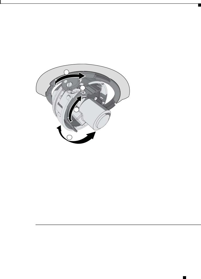
Step 6 Position the camera:
a.View the camera image using the service jack or a Web browser.
b.Unlock the tab locks located on each side of the camera.
c.Manually rotate and tilt the camera module to position the camera. Do not over-rotate the module.
d.Lock the tab locks to secure the camera.
Figure 2-3 Positioning the Camera
1
2
3
4
279055
1 |
Pan 368° |
3 |
Rotate 355° |
|
|
|
|
2 |
Tab lock |
4 |
Tilt 180° |
|
|
|
|
Step 7 Focus the lens:
a.View the camera image using the service jack or a Web browser.
b.Press the auto back focus button once to center the focus mechanism. The button is located on the rim of the back box.
c.Manually adjust the zoom and focus of the lens to the desired field of view (refer to the instructions shipped with the lens).
d.Press and hold the back focus button for three seconds to start the auto back focus mechanism.
Step 8 Install the dome liner and lower dome (refer to “Dome Liner and Lower Dome Installation” section on page 2-7).
Cisco Video Surveillance 5010/5011 Indoor Fixed HD IP Dome Camera User Guide
|
OL-22669-02 |
2-3 |
|
|
|

Chapter 2 Installation
Surface Installation
Surface Installation
Warning Remove the foam insert from the back box before installing the system. The foam is inserted to secure the tilt ring; preventing damage to the optical chassis during shipment.
Step 1 Prepare the mounting surface:
a.Using the surface mount ring as a template, drill holes for the mounting hardware. Prepare the ceiling as follows:
–Standard ceiling: When mounting the dome camera to a standard ceiling, use either 6-32 toggle bolts (not supplied)
or #8 x 3.50-inch self-tapping screws (not supplied).
–Concrete ceiling: When mounting the dome camera to a concrete system, use 8-32 studs and nuts (not supplied).
b.Drill a hole in the ceiling for wiring.
c.Pull all wiring through the hole and terminate all wires (if not already terminated).
d.Attach the surface mount ring to the mounting surface.
Step 2 Install the lens on the back box:
Note Megapixel lenses are designed and tested to deliver optimal image quality to megapixel cameras. A standard definition lens installed on a megapixel camera will limit the resolution of the camera and create poor image quality.
a.Remove the cover from the lens mount.
b.Screw the lens onto the lens mount. Be careful to prevent dust from entering the space between the lens and the imager. If necessary, use clean, compressed air to remove any foreign matter (refer to the instructions shipped with the lens). Make sure the lens does not touch the camera imager when installed.
c.Connect the auto iris lens to the 4-pin connector located on the side of the camera. Pin connections for the iris drive connector are as follows:
Figure 2-4
3
 4
4
1
 2
2
Lens Pin Connections
278768
|
|
|
|
Pin |
DC (AID) Auto Iris Lens |
|
|
|
|
|
|
||||
1 |
Control coil negative (–) |
||||||
|
|
|
|
||||
2 |
Control coil positive (+) |
||||||
|
|
|
|
||||
3 |
Drive coil positive (+) |
||||||
|
|
|
|
||||
4 |
Drive coil negative (–) |
||||||
|
|
|
|
|
|
|
|
|
|
|
Cisco Video Surveillance 5010/5011 Indoor Fixed HD IP Dome Camera User Guide |
||||
|
|
|
|||||
|
|
|
|
|
|
|
|
|
2-4 |
|
|
|
|
OL-22669-02 |
|
|
|
|
|
|
|||
Chapter 2 Installation
Surface Installation
Step 3 Connect the wiring to the side of the back box:
a.Plug the network cable into the RJ-45 connector on the side of the camera. If the network has no PoE, connect a 24 VAC Class 2 power supply to the 24 VAC power connector. Refer to “Wiring” section on page 2-10 for wiring connections.
b.Connect the necessary wiring for alarms and relays (refer to “Wiring” section on page 2-10 for more information).
Step 4 Install the back box in the surface mount ring by compressing the spring clips and pushing the back box through the hole. Tighten the machine screws completely to secure the back box to the ceiling.
Figure 2-5 Surface Back Box Installation
279050
Step 5 Apply power to the camera. The camera will complete a configuration sequence; the green LED flashes five times per second for approximately two minutes and then turns solid after the sequence is complete.
Note If the camera is not connected to a DHCP server and DHCP is enabled, the configuration sequence might take up to five minutes to complete.
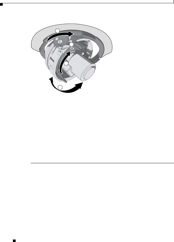
Step 6 Position the camera:
a.View the camera image using the service jack or a Web browser.
b.Unlock the tab locks located on each side of the camera.
c.Manually rotate and tilt the camera module to position the camera. Do not over-rotate the module.
d.Lock the tab locks to secure the camera.
Cisco Video Surveillance 5010/5011 Indoor Fixed HD IP Dome Camera User Guide
|
OL-22669-02 |
2-5 |
|
|
|
Chapter 2 Installation
Surface Installation
Figure 2-6 Positioning the Camera
1
2
3
4
279055
1 |
Pan 368° |
3 |
Rotate 355° |
|
|
|
|
2 |
Tab lock |
4 |
Tilt 160° |
|
|
|
|
Step 7 Focus the lens:
a.View the camera image using the service jack or a Web browser.
b.Press the auto back focus button once to center the focus mechanism. The button is located on the rim of the back box.
c.Manually adjust the zoom and focus of the lens to the desired field of view (refer to the instructions shipped with the lens).
d.Press and hold the back focus button for three seconds to start the auto back focus mechanism.
Step 8 Install the dome liner and lower dome (refer to “Dome Liner and Lower Dome Installation” section on page 2-7).
Cisco Video Surveillance 5010/5011 Indoor Fixed HD IP Dome Camera User Guide
2-6 |
OL-22669-02 |
|
|
Chapter 2 Installation
Dome Liner and Lower Dome Installation
Dome Liner and Lower Dome Installation
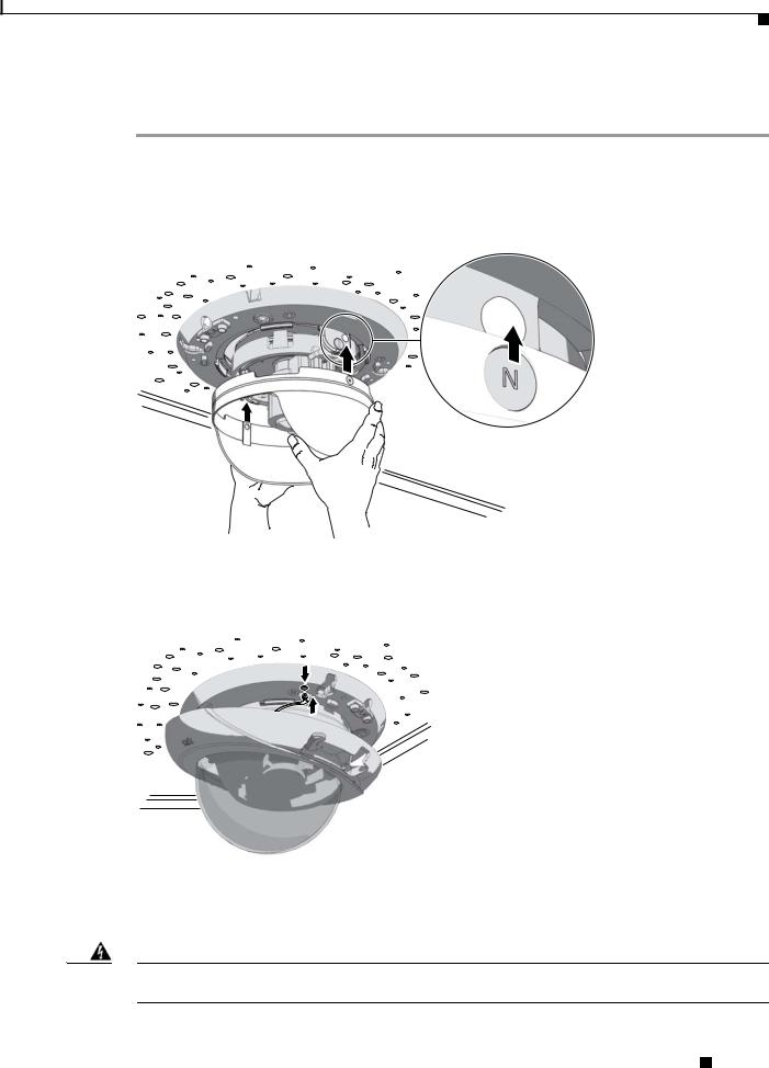
Step 1 Align the magnets on the dome liner with the magnets located on the camera module.
Figure 2-7 Installing the Dome Liner
279051
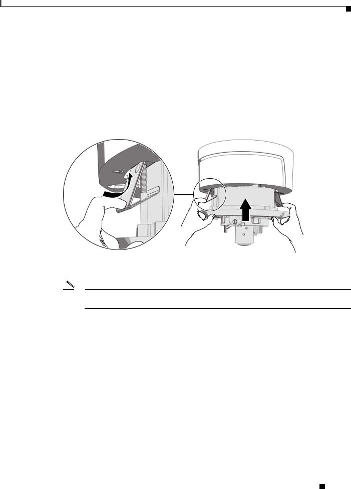
Step 2 Attach the leash of the lower dome to the back box.
Figure 2-8 Attaching the Leash
279056
Step 3 Move the lower dome latches away from the bubble until you hear a click indicating the latches are open. Align the lower dome latches with the slots located on the camera module (refer to Figure 2-9 on page 2-8).
Warning The lower dome latches must be in the open position. Never force the lower dome latches into the slots of the camera module.
Cisco Video Surveillance 5010/5011 Indoor Fixed HD IP Dome Camera User Guide
|
OL-22669-02 |
2-7 |
|
|
|

Chapter 2 Installation
Dome Liner and Lower Dome Installation
Figure 2-9 Aligning the Lower Dome with Camera
279052
Step 4 Move the lower dome latches toward the bubble until you hear a click.
Figure 2-10 Locking the Dome
279053
Step 5 Turn the top cover of the lower dome 90-degrees to conceal the camera latches, LED, and service jack.
Figure 2-11 Positioning the Top Cover of the Lower Dome
279054
Cisco Video Surveillance 5010/5011 Indoor Fixed HD IP Dome Camera User Guide
2-8 |
OL-22669-02 |
|
|
Chapter 2 Installation
Service Cable
Service Cable
The dome camera includes a service port that outputs camera video. Use it at the installation site to set up the field of view and to focus the camera.
To assemble a service cable for the camera, you will need to purchase the following items from an electronics supply store:
Qty Description
1 2.5 mm stereo plug (male)
1 CPM 88 miniature coaxial connector
1 RG174/U coaxial cable
1 1/8-inch shrink fit tubing, 1/2-inch long
To assemble the cable:
Step 1 Attach the CPM 88 miniature coaxial connector to one end of the cable. Follow the directions supplied with the miniature coaxial connector.
Step 2 Attach the 2.5 mm stereo plug to the other end of the coaxial cable (refer to Figure 2-12 on page 2-10):
a.Remove the support sleeve from the plug.
b.Slip the shrink fit tubing and support sleeve over the end of the cable.
c.Prepare the cable:
d.Strip back the outer jacket 0.318 inch (8.06 mm) inch from the end of the cable.
e.Pull back the coaxial braid shield.
f.Strip back the insulating material 0.125 inch (3.18 mm) inch to expose the center conductor.
g.Solder the center connector of the cable to the center pin of the plug.
h.Pull the coaxial braid shield back through the crimp pin and solder it to the top of the crimp pin arm.
i.Crimp the end of the crimp pin around the cable.
j.Heat the shrink fit tubing around the center conductor and shoulder pin.
k.Reassemble the support sleeve and the plug.
Cisco Video Surveillance 5010/5011 Indoor Fixed HD IP Dome Camera User Guide
|
OL-22669-02 |
2-9 |
|
|
|
Chapter 2 Installation
Wiring
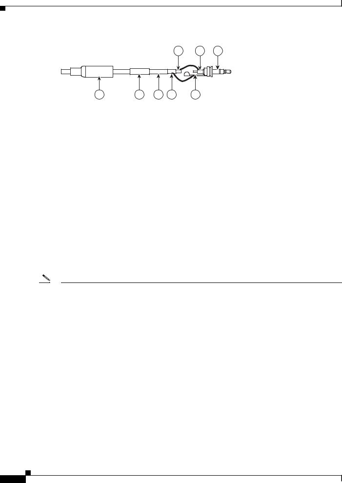
Figure 2-12 Attaching the 2.5 mm Monaural Headphone Plug
1 2 3
8 |
7 |
6 |
5 |
4 |
278793
1 |
2.5 mm Stereo Plug |
5 |
Shrink Fit Tubing |
|
|
|
|
2 |
Plug Shoulder Pin |
6 |
Coaxial Cable |
|
|
|
|
3 |
Center Conductor |
7 |
Coaxial Braid Shield |
|
|
|
|
4 |
Support Sleeve |
8 |
Crimp Pin Arm |
|
|
|
|
|
|
|
|
Wiring
Cat5 or Cat6 Cable
Connect a Cat5 or Cat 6 cable to the RJ-45 network port. The 8-pin connector includes video and PoE for the camera. PoE (IEEE 802.3af Class 3) injects power over the same cabling that carries the network data, eliminating the need for a separate power supply. This simplifies the installation and operation of the camera without affecting network performance.
Note |
• |
The camera will autosense and configure itself to use either a crossover cable or a straight cable. |
|
• |
A CAT5 is sufficient for 100 MHz transmission. Use a CAT6 cable for both 100 and 1000 MHz |
|
|
transmission. |
|
|
|
|
Cisco Video Surveillance 5010/5011 Indoor Fixed HD IP Dome Camera User Guide |
2-10 |
OL-22669-02 |
Chapter 2 Installation
Wiring
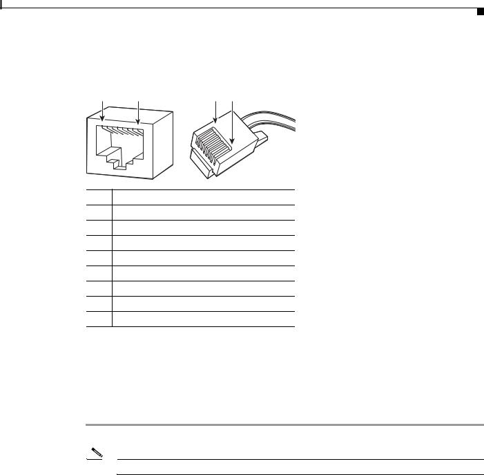
Refer to Figure 2-13 for pin descriptions.
Figure 2-13 Cat5 or Cat6 Cable Pin Descriptions
1 |
8 |
8 |
1 |
1 |
2 |
3 |
4 |
5 |
6 |
7 |
8 |
|
|
|
|||||
|
|
|
|
|
8
7 6
5
4
3
2
1
279057
Pin Function
1TX+
2TX–
3RX+
4PoE 1-2
5PoE 1-2
6RX–
7PoE 3-4
8PoE 3-4
24 VAC Connector
Single Camera Wiring
If PoE is not available:
Step 1 Connect the 24 VAC wires to the supplied 2-pin connector (refer to Figure 2-14).
Note Only use the 24 VAC wires if PoE is not available.
Step 2 Attach the mating connector to the green connector on the side of the camera.
|
|
Cisco Video Surveillance 5010/5011 Indoor Fixed HD IP Dome Camera User Guide |
|
|
|
|
|
|
|||
|
OL-22669-02 |
|
|
2-11 |
|
|
|
|
|
||
Loading...