


38AH044-134 Air-Cooled Condensing Units 50/60 Hz
Installation, Start-Up and
Service Instructions
CONTENTS
Page
SAFETY CONSIDERATIONS . . . . . . . . . . . . . . . . 1
INSTALLATION . . . . . . . . . . . . . . . . . . . . . . . . . . . . 1-37
Step 1 Ð Rig and Place Unit . . . . . . . . . . . . . . . 1
·DOMESTIC UNITS
·EXPORT UNITS
·PLACING UNITS
Step 2 Ð Check Compressor Mounting . . . . . 3
·UNITS 38AH044-084
·UNITS 38AH094-134
Step 3 Ð Make Refrigerant Piping
Connections . . . . . . . . . . . . . . . . . . . . . . . . . . . . . . 14
·UNITS 38AH044-084
·UNITS 38AH094-134
Step 4 Ð Make Electrical Connections . . . . . . 23
·POWER SUPPLY
·FIELD POWER CONNECTIONS
·MAIN POWER
·CONTROL CIRCUIT WIRING
Step 5 Ð Install Accessories . . . . . . . . . . . . . . . |
37 |
·LOW-AMBIENT OPERATION
·MISCELLANEOUS ACCESSORIES
PRE-START-UP . . . . . . . . . . . . . . . . . . . . . . . . . . |
37,38 |
START-UP . . . . . . . . . . . . . . . . . . . . . . . . . . . . . . . . 38-45 SERVICE . . . . . . . . . . . . . . . . . . . . . . . . . . . . . . . . . . 46-49 CONTROL . . . . . . . . . . . . . . . . . . . . . . . . . . . . . . . . 49-52 TROUBLESHOOTING . . . . . . . . . . . . . . . . . . . . . . 53,54 START-UP CHECKLIST . . . . . . . . . . . . . . . CL-1, CL-2
SAFETY CONSIDERATIONS
Installing, starting up, and servicing this equipment can be hazardous due to system pressures, electrical components, and equipment location (roofs, elevated structures, etc.).
Only trained, quali®ed installers and service mechanics should install, start up, and service this equipment.
Untrained personnel can perform basic maintenance functions, such as cleaning coils. All other operations should be performed by trained service personnel.
When working on the equipment, observe precautions in the literature, and on tags, stickers, and labels attached to the equipment and any other safety precautions that may apply.
·Follow all safety codes.
·Wear safety glasses and work gloves.
·Use care in handling, rigging, and setting bulky equipment.
ELECTRIC SHOCK HAZARD.
Open all remote disconnects before servicing this equipment.
INSTALLATION
Step 1 Ð Rig and Place Unit Ð All units are designed for overhead rigging, and it is important that this method be used. Lifting holes are provided in the frame base rails, which are marked for rigging (see rigging label on the unit and Tables 1, 2A, and 2B for rigging weights and center of gravity). It is recommended that ®eld-supplied pipes, of suf®cient length to extend at least 12-in. (305 mm) beyond the frame, be passed through the holes.
To maintain unit stability while lifting, use 4 cables, chains, or straps of equal length. Attach one end of each cable to one pipe end and the other end of each cable to the overhead rigging point.
Use spreader bars or frame to keep the cables, chains, and straps clear of the unit sides. Leave standard coil protection packaging in place during rigging to provide protection to coils. Remove and discard all coil protection after rigging cables are detached.
DOMESTIC UNITS Ð For units 38AH044-084, 124, and 134; standard unit packaging consists of coil protection only. There is no standard packaging provided for units 38AH094 and 104. Skids are not provided. If overhead rigging is not available at the jobsite, place the unit on a skid or pad before dragging or rolling. When rolling, use a minimum of 3 rollers. When dragging, pull the pad or skid. Do not apply force to the unit. When in ®nal position, raise from above to lift unit off the pad or skid.
EXPORT UNITS Ð All export units are mounted on skids with vertical coil protection. Leave the unit on the skid until it is in ®nal position. While on the skid, the unit can be rolled or skidded. Apply force to the skid, not to the unit. Use a minimum of 3 rollers when rolling. When in ®nal position, raise from above to remove the skid.
PLACING UNITS
Units 38AH044-084 Ð Refer to Fig. 1 and 2 for air¯ow clearances. Recommended minimum clearances are 6 ft (1829 mm) for unrestricted air¯ow and service on sides of unit, 5 ft (1524 mm) on ends, and unrestricted clear air space above the unit. Provide ample space to connect liquid and suction lines to indoor unit. For multiple units, allow 8 ft (2440 mm) separation between units for air¯ow and service.
Do not forklift these units unless the unit is attached to a skid designed for forklifting.
Manufacturer reserves the right to discontinue, or change at any time, speci®cations or designs without notice and without incurring obligations.
Book |
1 |
|
PC 111 |
Catalog No. 563-704 |
Printed in U.S.A. |
Form 38AH-15SI |
Pg 1 |
10-98 |
Replaces: 38AH-14SI |
Tab |
3a |
|
|
|
|
|
|
|
|
|
|
|
|
|
|
|
|
|
|
The placement area must be level and strong enough to support the operating weight of the unit (see Table 3A or 3B). When unit is in proper location, use of mounting holes in base rails is recommended for securing unit to supporting structure. For mounting unit on vibration isolators, a perimeter support channel between the unit and the isolators is recommended. Fasteners for mounting unit are ®eld supplied. Be sure to mount unit level to ensure proper oil return to compressors.
Units 38AH094-134 Ð Refer to Fig. 3-6 for air¯ow clearances. Recommended minimum clearances are 6 ft (1829 mm) for unrestricted air¯ow and service on sides of unit, 5 ft (1524 mm) on ends, and unrestricted clear air space above unit. Provide ample space to connect liquid and suction lines to indoor unit. For multiple units, allow 8 ft (2440 mm) separation between units for air¯ow and service.
Do not forklift these units unless the unit is attached to a skid designed for forklifting.
The placement area must be level and strong enough to support the operating weight of the unit. See Table 4A or 4B. Refer to the following paragraphs for the proper placement of the unit.
Units 38AH094,104 Ð For mounting units on vibration isolators, a perimeter support channel is required between the unit and the support isolators. The perimeter support channel must be sized to support the fully assembled unit. Do not
support units on individual isolation supports. Support channel, hardware, and fasteners are ®eld supplied. When unit is in proper location, level unit and bolt into position with ®eldsupplied bolts.
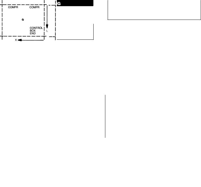
Units 38AH124,134 Ð For ease of shipment and handling, unit 38AH124 is shipped as 2 modules (124A and 124B) and unit 38AH134 is shipped as 2 modules (134A and 134B). The modules must be connected at the ®nal installation site with the factory-shipped piping and sheet metal trim kit mounted on Module 124A or 134A. See Fig. 7.
Do not move assembled 38AH124 or 134 units as a single assembly. Always move modules individually during installation or at any other time.
Mark installation site for placement of Modules 124A and 124B or Modules 134A and 134B. See Table 4A or 4B for ®nal assembled dimensions. A service space of 24 in. (610 mm) is required between the 2 modules for piping and sheet metal trim installation.
Place Module 124A or 134A in position, ensuring that the control box is at the end opposite the service space. See Fig. 8.
Remove sheet metal and tubing from Module 124A or 134A sheet metal trim kit (Fig. 7). Remove sheet metal cover panels from return-bend end of unit facing the service space. See Fig. 8. These panels may be discarded or saved for reinstallation if module is moved from site. See Fig. 9.
Table 1 Ð Rigging Center of Gravity Ð in. (mm)
UNIT |
|
|
044 |
054 |
|
064 |
074 |
084 |
|
094 |
|
104 |
MODULE |
MODULE |
MODULE |
MODULE |
||
38AH |
|
|
|
|
|
124A |
124B |
|
134A |
134B |
||||||||
|
|
|
|
|
|
|
|
|
|
|
|
|
|
|||||
Dimension X |
|
49 (1232) |
48 (1224) |
50 (1260) |
57 (1443) |
57 (1448) |
66 (1676) |
63 (1600) |
50 (1260) |
Ð |
50 (1260) |
Ð |
||||||
Dimension Y |
|
39 |
(984) |
39 |
(978) |
38 |
(968) |
39 (993) |
39 (991) |
31 |
(787) |
34 |
(851) |
38 (968) |
Ð |
38 |
(968) |
Ð |
Dimension X-C |
|
49 (1234) |
48 (1229) |
50 (1261) |
56 (1425) |
56 (1422) |
66 (1676) |
63 (1600) |
50 (1260) |
Ð |
50 (1260) |
Ð |
||||||
Dimension Y-C |
|
39 |
(993) |
39 |
(991) |
39 |
(986) |
40 (1006) |
40 (1008) |
31 |
(787) |
34 |
(851) |
39 (986) |
Ð |
39 |
(986) |
Ð |
Dimension K |
|
|
Ð |
Ð |
|
Ð |
|
Ð |
Ð |
Ð |
Ð |
|
Ð |
50 |
(1260) |
|
Ð |
57 (1443) |
Dimension L |
|
|
Ð |
Ð |
|
Ð |
|
Ð |
Ð |
Ð |
Ð |
|
Ð |
38 |
(968) |
|
Ð |
39 (993) |
Dimension K-C |
|
|
Ð |
Ð |
|
Ð |
|
Ð |
Ð |
Ð |
Ð |
|
Ð |
50 |
(1260) |
|
Ð |
56 (1425) |
Dimension L-C |
|
|
Ð |
Ð |
|
Ð |
|
Ð |
Ð |
Ð |
Ð |
|
Ð |
39 |
(986) |
|
Ð |
40 (1006) |
|
|
|
|
|
|
|
|
|
|
|
|
|
|
|
|
|
|
|
LEGEND |
|
|
|
|
|
|
|
|
|
|
|
|
|
|
|
|
|
|
Ð Ð |
Not Applicable |
C Ð |
Copper Fin Coils |
TOP VIEW, TYPICAL |
124, 134 ONLY |
2
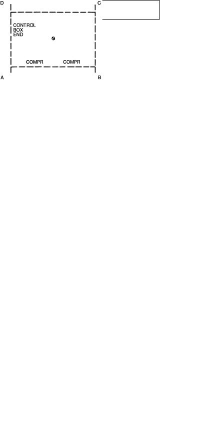
Remove sheet metal cover panels from return-bend end of Module 124B or 134B. Place Module 124B or 134B in position. The exposed return-bend ends of each module are now opposite each other and facing the service space. The compressors of each module are on opposite sides of the unit.
IMPORTANT: Modules must be placed 24 in. (610 mm) apart and square relative to each other.
The modules are now in position for piping installation and ®nal assembly. See Fig. 8. For mounting units on vibration isolators, a perimeter support channel is required between the assembled unit and the support isolators. The perimeter support channel must be sized to support the fully assembled unit. Do not support modules on individual isolation supports. Support channel, hardware, and fasteners are ®eld supplied.
When unit is in proper location, level unit and bolt into position with ®eld-supplied bolts.
Table 2A Ð Operational Corner Weights with Refrigerant Charge (Approximate) Ð Lb
UNIT |
|
TOTAL |
OPERATIONAL CORNER WEIGHT |
|||
38AH |
|
WEIGHT |
A |
B |
C |
D |
044 |
|
3259 |
939 |
893 |
695 |
732 |
044C |
|
3547 |
1013 |
967 |
765 |
802 |
054 |
|
3309 |
964 |
905 |
697 |
742 |
054C |
|
3597 |
1034 |
978 |
771 |
814 |
064 |
|
3565 |
1018 |
1011 |
765 |
771 |
064C |
|
3998 |
1125 |
1117 |
874 |
879 |
074 |
|
3812 |
1146 |
986 |
777 |
903 |
074C |
|
4229 |
1272 |
1059 |
862 |
1035 |
084 |
|
4057 |
1220 |
1049 |
827 |
961 |
084C |
|
4735 |
1425 |
1186 |
965 |
1159 |
094 |
|
5088 |
1114 |
2192 |
1182 |
601 |
094C |
|
5813 |
1273 |
2504 |
1350 |
686 |
104 |
|
5435 |
1240 |
2138 |
1302 |
755 |
104C |
|
6160 |
1405 |
2423 |
1476 |
856 |
MODULE |
|
|
|
|
|
|
38AH |
|
|
|
|
|
|
124A |
|
3630 |
1037 |
1030 |
779 |
785 |
124A-C |
|
4063 |
1144 |
1137 |
889 |
894 |
124B |
|
3630 |
1037 |
1030 |
779 |
785 |
124B-C |
|
4063 |
1144 |
1137 |
889 |
894 |
134A |
|
3630 |
1037 |
1030 |
779 |
785 |
134A-C |
|
4063 |
1144 |
1137 |
889 |
894 |
134B |
|
3877 |
1167 |
997 |
789 |
924 |
134B-C |
|
4294 |
1293 |
1080 |
874 |
1047 |
|
|
|
|
|
|
|
LEGEND
C Ð Copper Fin Coils
NOTE: Total weight may differ from summation of corner weights due to rounding of numerals.
Step 2 Ð Check Compressor Mounting
UNITS 38AH044-084 Ð Compressors are mounted on pans and are held down by 4 bolts during shipment. After unit is installed, loosen each of these bolts until the snubber washer can be moved with ®nger pressure. See Fig. 10.
UNITS 38AH094-134 Ð Units 38AH094 and 104 compressors are mounted on rails and held down by rail bolts during shipment. After unit is installed, loosen the rail bolts to allow the rails and compressors to ¯oat freely on the springs located under the rails. See Fig. 10.
Units 38AH124 and 134 compressors are mounted on pans and are held down by 4 bolts during shipment. After unit is installed, loosen each of these bolts until snubber washer can be moved with ®nger pressure. See Fig. 10.
Table 2B Ð Operational Corner Weights with Refrigerant Charge (Approximate) Ð Kg
UNIT |
|
TOTAL |
OPERATIONAL CORNER WEIGHT |
|||
38AH |
|
WEIGHT |
A |
B |
C |
D |
044 |
|
1478 |
426 |
405 |
316 |
332 |
044C |
|
1609 |
460 |
438 |
347 |
364 |
054 |
|
1501 |
437 |
411 |
316 |
337 |
054C |
|
1632 |
469 |
444 |
350 |
369 |
064 |
|
1617 |
462 |
459 |
347 |
350 |
064C |
|
1813 |
510 |
508 |
397 |
399 |
074 |
|
1729 |
520 |
447 |
352 |
410 |
074C |
|
1918 |
577 |
481 |
391 |
470 |
084 |
|
1840 |
553 |
476 |
375 |
436 |
084C |
|
2148 |
646 |
538 |
438 |
526 |
094 |
|
2308 |
505 |
994 |
536 |
272 |
094C |
|
2637 |
577 |
1136 |
612 |
311 |
104 |
|
2465 |
562 |
970 |
591 |
342 |
104C |
|
2794 |
637 |
1099 |
670 |
388 |
MODULE |
|
|
|
|
|
|
38AH |
|
|
|
|
|
|
124A |
|
1647 |
470 |
467 |
353 |
356 |
124A-C |
|
1843 |
519 |
516 |
403 |
405 |
124B |
|
1647 |
470 |
467 |
353 |
356 |
124B-C |
|
1843 |
519 |
516 |
403 |
405 |
134A |
|
1647 |
470 |
467 |
353 |
356 |
134A-C |
|
1843 |
519 |
516 |
403 |
405 |
134B |
|
1759 |
529 |
452 |
358 |
419 |
134B-C |
|
1948 |
587 |
490 |
396 |
475 |
|
|
|
|
|
|
|
LEGEND
C Ð Copper Fin Coils
NOTE: Total weight may differ from summation of corner weights due to rounding of numerals.
TOP VIEW, TYPICAL
3
|
DUAL CKT |
SINGLE CKT |
|
|
|
|
|
SUCTION |
21¤89 Dia [54 mm] |
25¤89 Dia [67 mm] |
|
CONNECTION(S) |
|
|
|
LIQUID |
7¤89 Dia [22 mm] |
11¤89 Dia [29 mm] |
|
CONNECTION(S) |
|
|
|
SUCTION C |
28-11¤169 |
[627mm] |
18-105¤169 [567mm] |
LIQUID D |
18-101¤169 [561mm] |
18-105¤169 [567mm] |
|
SUCTION (Ckt A) |
18-713¤169 [503mm] |
28-5¤89 [626mm] |
|
SUCTION (Ckt B) |
28-5¤89 |
[626mm] |
Ð |
LIQUID (Ckt A) |
28-53¤49 |
[756mm] |
28-105¤89 [879mm] |
LIQUID (Ckt B) |
28-105¤89 |
[879mm] |
Ð |
Chart 1, Field Power Supply Connections
|
UNIT |
|
VOLTAGE |
Hz |
DIAMETER Ð in. [mm] |
QTY |
||
|
044 |
|
230 |
50 |
35¤8 [92] |
1 |
||
044, 054 |
208/230 |
60 |
35¤8 [92] |
1 |
||||
346, 380/415 |
50 |
21¤2 [63] |
1 |
|||||
|
|
|
||||||
044, 054, 064 |
460,575,380 |
60 |
21¤2 |
[63] |
1 |
|||
|
064 |
|
208/230 |
60 |
21¤2 |
[63] |
2 |
|
|
|
346, 380/415 |
50 |
35¤8 |
[92] |
1 |
||
|
|
|
||||||
|
LEGEND |
|
|
|
|
|||
C |
Ð |
Copper Fin Coils |
|
|
|
|
||
MTG |
Ð |
Mounting |
|
|
|
|
||
SAE |
Ð |
Society of Automotive Engineers |
|
|
||||
NOTES:
1. The approximate operating weight of the unit is:
38AH-044--- |
3259 lb [1478 kg] |
38AH-044--C |
3547 lb [1609 kg] |
38AH-054--- |
3309 lb [1501 kg] |
38AH-054--C |
3597 lb [1632 kg] |
38AH-064--- |
3565 lb [1617 kg] |
38AH-064--C |
3998 lb [1813 kg] |
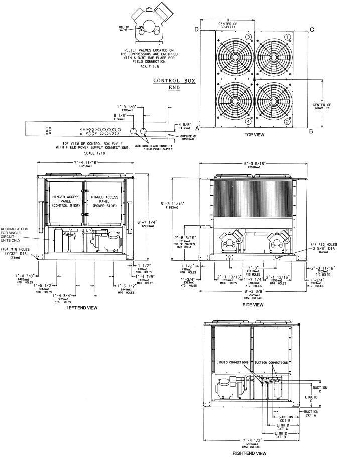
2.Unit must have clearances for air¯ow as follows: Top Ð Do not restrict in any way.
Ends Ð 5 ft [1524 mm] Sides Ð 6 ft [1829 mm]
3.Mounting holes may be used to mount unit to concrete pad. They are not recommended for mounting unit to spring isolators. If spring isolators are used, a perimeter support channel between the unit and the isolators is recommended.
4.One 35¤89 (92 mm) diameter hole is recommended for single-entry power on size 064 (208/230-v) units.
5.See Table 1 for rigging center of gravity (Dimensions X,Y). See Table 2A and 2B for A-D corner weights.
6.Circled numerals in Top View refer to condenser fans by position.
Fig. 1 Ð Dimensions Ð Units 38AH044,054,064
4
|
DUAL CKT |
SINGLE CKT |
|
|
|
|
|
SUCTION |
21¤89 Dia [54 mm] |
25¤89 Dia [67 mm] |
|
CONNECTION(S) |
|
|
|
LIQUID |
7¤89 Dia [22 mm] |
11¤89 Dia [29 mm] |
|
CONNECTION(S) |
|
|
|
SUCTION C |
28-11¤169 |
[627mm] |
18-105¤169 [567mm] |
LIQUID D |
18-101¤169 [561mm] |
18-105¤169 [567mm] |
|
SUCTION (Ckt A) |
18-713¤169 [503mm] |
28-5¤89 [626mm] |
|
SUCTION (Ckt B) |
28-5¤89 |
[626mm] |
Ð |
LIQUID (Ckt A) |
28-53¤49 |
[756mm] |
28-105¤89 [879mm] |
LIQUID (Ckt B) |
28-105¤89 |
[879mm] |
Ð |
Chart 1, Field Power Supply Connections
UNIT |
|
VOLTAGE |
Hz |
DIAMETER Ð in. [mm] |
QTY |
|
074 |
|
208/230 |
60 |
21¤2 [63] |
2 |
|
|
460 |
60 |
21¤2 [63] |
1 |
||
|
|
|
||||
|
|
|
346, 380/415 |
50 |
35¤8 [92] |
1 |
074, 084 |
|
380 |
60 |
35¤8 [92] |
1 |
|
|
|
|
575 |
60 |
21¤2 [63] |
1 |
084 |
|
208/230 |
60 |
35¤8 [92] |
2 |
|
|
460 |
60 |
35¤8 [92] |
1 |
||
|
|
|
||||
|
LEGEND |
|
|
|
||
C |
Ð |
Copper Fin Coils |
|
|
|
|
MTG |
Ð |
Mounting |
|
|
|
|
SAE |
Ð |
Society of Automotive Engineers |
|
|||
NOTES: |
|
|
|
|
|
|
1. The approximate operating weight of the unit is: |
|
|||||
38AH-074--- |
3812 lb (1729 kg) |
|
||||
38AH-074--C |
4229 lb (1918 kg) |
|
||||
38AH-084--- |
4057 lb (1840 kg) |
|
||||
38AH-084--C |
4735 lb (2148 kg) |
|
||||
2.Unit must have clearances for air¯ow as follows: Top Ð Do not restrict in any way.
Ends Ð 5 ft [1524 mm] Sides Ð 6 ft [1829 mm]
3.Mounting holes may be used to mount unit to concrete pad. They are not recommended for mounting unit to spring isolators. If spring isolators are used, a perimeter support channel between the unit and the isolators is recommended.
4.See Table 1 for rigging center of gravity (Dimensions X,Y). See Table 2A and 2B for A-D corner weights.
5.Circled numerals in Top View refer to condenser fans by position.
Fig. 2 Ð Dimensions Ð Units 38AH074,084
5
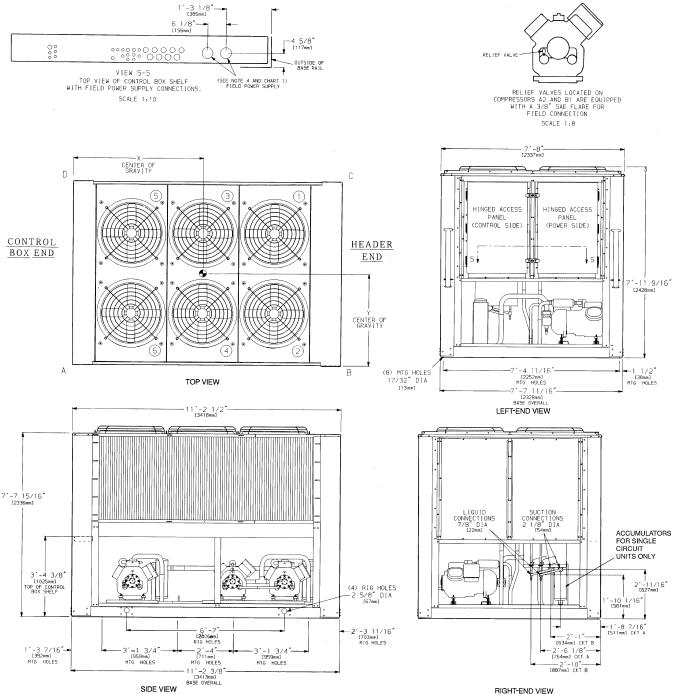
Chart 1, Field Power Supply Connections
UNIT |
VOLTAGE |
Hz |
DIAMETER Ð in. (mm) |
QUANTITY |
||
38AH |
||||||
|
|
|
|
|
||
|
208/230 |
60 |
35¤8 |
(92) |
2 |
|
094 |
460, 575, |
60 |
35¤8 |
(92) |
1 |
|
380 |
||||||
|
|
|
|
|
||
|
346, 380/415 |
50 |
35¤8 |
(92) |
1 |
|
|
LEGEND |
|
C |
Ð Copper Fin Coils |
|
MTG |
Ð |
Mounting |
SAE |
Ð |
Society of Automotive Engineers |
NOTES:
1. The approximate operating weight of the unit is:
38AH-094--- |
5088 lb (2308 kg) |
38AH-094--C |
5813 lb (2637 kg) |
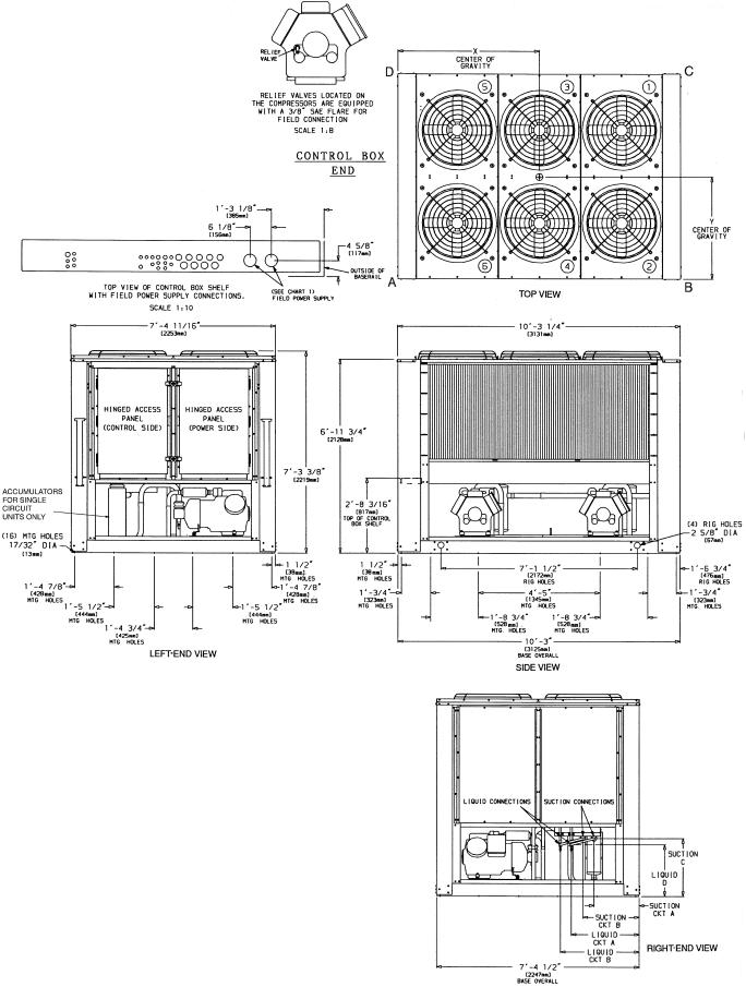
2.Unit must have clearances for air¯ow as follows: Top Ð Do not restrict in any way.
Ends Ð 5 ft [1524 mm] Sides Ð 6 ft [1829 mm]
3.Mounting holes may be used to mount unit to concrete pad. They are not recommended for mounting unit to spring isolators.
4.Two 35¤89 (92-mm) dia holes are recommended for parallel conductors on 208/230 v units.
5.Circled numerals in Top View refer to condenser fans by position.
6.If spring isolators are used, a perimeter support channel between the unit and the isolators is recommended.
7.See Table 1 for rigging center of gravity (Dimensions X,Y). See Table 2A and 2B for A-D corner weights.
Fig. 3 Ð Dimensions Ð Unit 38AH094
6
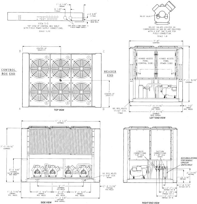
Chart 1, Field Power Supply Connections
UNIT |
VOLTAGE |
Hz |
DIAMETER Ð in. (mm) |
QUANTITY |
||
38AH |
||||||
|
|
|
|
|
||
|
208/230 |
60 |
35¤8 |
(92) |
2 |
|
104 |
460, 575, |
60 |
35¤8 |
(92) |
1 |
|
380 |
||||||
|
|
|
|
|
||
|
346, 380/415 |
50 |
35¤8 |
(92) |
1 |
|
|
LEGEND |
|
C |
Ð Copper Fin Coils |
|
MTG |
Ð |
Mounting |
SAE |
Ð |
Society of Automotive Engineers |
NOTES:
1. The approximate operating weight of the unit is:
38AH-104--- |
5435 lb (2465 kg) |
38AH-104--C |
6160 lb (2794 kg) |
2.Unit must have clearances for air¯ow as follows: Top Ð Do not restrict in any way.
Ends Ð 5 ft [1524 mm] Sides Ð 6 ft [1829 mm]
3.Mounting holes may be used to mount unit to concrete pad. They are not recommended for mounting unit to spring isolators.
4.Two 35¤89 (92-mm) dia holes are recommended for parallel conductors on 208/230 v units.
5.Circled numerals in Top View refer to condenser fans by position.
6.If spring isolators are used, a perimeter support channel between the unit and the isolators is recommended.
7.See Table 1 for rigging center of gravity (Dimensions X,Y). See Table 2A and 2B for A-D corner weights.
Fig. 4 Ð Dimensions Ð Unit 38AH104
7
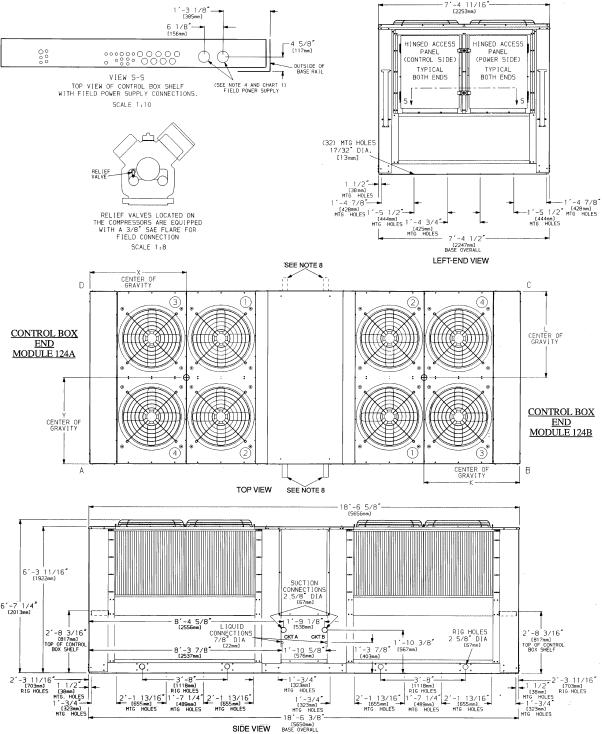
Chart 1, Field Power Supply Connections
UNIT |
VOLTAGE |
Hz |
DIAMETER |
QUANTITY |
|||
38AH |
(in.) |
||||||
|
|
|
|||||
|
|
208/230 |
60 |
35¤8 |
(92) |
1 |
|
124A |
460, 575, |
60 |
21¤2 |
(63) |
1 |
||
124B |
380 |
||||||
|
|
|
|
||||
|
|
346, 380/415 |
50 |
35¤8 |
(92) |
1 |
|
|
LEGEND |
|
|
|
|
||
C |
Ð Copper Fin Coils |
|
|
|
|||
MTG |
Ð Mounting |
|
|
|
|
||
SAE |
Ð |
Society of Automotive Engineers |
|
||||
NOTES:
1. The approximate operating weight of the unit is:
38AH-124--- |
7260 lb (3293 kg) |
38AH-124--C |
8126 lb (3686 kg) |
2.Unit must have clearances for air¯ow as follows: Top Ð Do not restrict in any way.
Ends Ð 5 ft [1524 mm] Sides Ð 6 ft [1829 mm]
3.Mounting holes may be used to mount unit to concrete pad. They are not recommended for mounting unit to spring isolators.
4.One 35¤89 (92-mm) dia hole is recommended for single-entry power into each module (124A and 124B) of the 208/230-v units.
5.Circled numerals in Top View refer to condenser fans by position.
6.If spring isolators are used, a perimeter support channel between the unit and the isolators is recommended. Do not support each module separately.
7.Each module of the unit must be rigged into position separately. The unit must not be rigged after modules have been connected.
8.Suction and liquid connections can exit on either side of the unit.
9.Field power supply connections are required for each module.
10.See Table 1 for rigging center of gravity (Dimensions K,L,X,Y). See Table 2A and 2B for A-D corner weights.
Fig. 5 Ð Dimensions Ð Unit 38AH124
8
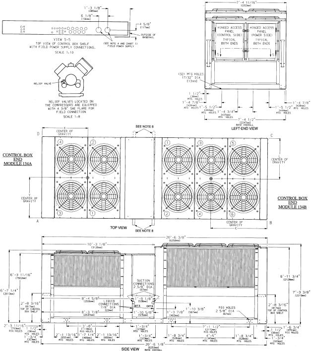
Chart 1, Field Power Supply Connections
UNIT |
|
VOLTAGE |
Hz |
DIAMETER Ð |
QUANTITY |
|
38AH |
|
in. (mm) |
||||
|
|
|
|
|||
|
|
|
208/230 |
60 |
35¤8 (92) |
1 |
134A |
|
460, 575, 380 |
60 |
21¤2 (63) |
1 |
|
|
|
|
346, 380/415 |
50 |
35¤8 (92) |
1 |
|
|
|
208/230 |
60 |
21¤2 (63) |
2 |
134B |
|
460, 575 |
60 |
21¤2 (63) |
1 |
|
|
380 |
60 |
35¤8 (92) |
1 |
||
|
|
|
||||
|
|
|
346, 380/415 |
50 |
35¤8 (92) |
1 |
|
LEGEND |
|
|
|
||
C |
Ð Copper Fin Coils |
|
|
|
||
MTG |
Ð Mounting |
|
|
|
||
SAE |
Ð |
Society of Automotive Engineers |
|
|||
NOTES:
1. The approximate operating weight of the unit is:
38AH-134--- |
7507 lb (3405 kg) |
38AH-134--C |
8357 lb (3791 kg) |
2.Unit must have clearances for air¯ow as follows: Top Ð Do not restrict in any way.
Ends Ð 5 ft [1524 mm] Sides Ð 6 ft [1829 mm]
3.Mounting holes may be used to mount unit to concrete pad. They are not recommended for mounting unit to spring isolators.
4.One 35¤89 (92-mm) dia hole is recommended for single-entry power into Module 134A and 208/230-v units. Single entry power into Module 134B is not recommended.
5.Circled numerals in Top View refer to condenser fans by position.
6.If spring isolators are used, a perimeter support channel between the assembled unit and the isolators is recommended. Do not support each module separately.
7.Each module of the unit must be rigged into position separately. The unit must not be rigged after modules have been connected.
8.Suction and liquid connections can exit on either side of the unit.
9.Field power supply connections are required for each module.
10.See Table 1A or 1B for rigging center of gravity (Dimensions K,L,X,Y). See Table 2A and 2B for A-D corner weights.
Fig. 6 Ð Dimensions Ð Unit 38AH134
9

Table 3A Ð Units 38AH044-084 Physical Data Ð 50/60 Hz (English)
38AH |
|
|
044 |
|
054 |
|
064 |
|
074 |
|
|
084 |
|||||
OPERATING WEIGHT WITH |
Cu-Al |
3259 |
3309 |
3565 |
3812 |
|
4057 |
||||||||||
REFRIGERANT (Approx) Ð Lb |
Cu-Cu |
3547 |
3597 |
3998 |
4229 |
|
4735 |
||||||||||
SHIP WEIGHT WITH COIL PROTECTION ONLY |
|
|
|
|
|
|
|
|
|
|
|
|
|
|
|
|
|
(Approx) Ð Lb |
Cu-Al |
3250 |
3290 |
3530 |
3780 |
|
4000 |
||||||||||
|
Cu-Cu |
3538 |
3578 |
3963 |
4197 |
|
4678 |
||||||||||
TYPICAL OPERATING REFRIGERANT |
|
|
|
|
|
|
|
R-22 |
|
|
|
|
|
|
|
||
Charge (Approx) Ð Lb |
|
|
62 |
|
72 |
|
88 |
|
104 |
|
|
130 |
|||||
Qty of Circuits |
Std |
|
2 |
|
2 |
|
2 |
|
2 |
|
|
2 |
|||||
|
Opt |
|
1 |
|
1 |
|
1 |
|
1 |
|
|
1 |
|||||
COMPRESSOR Type...Rpm |
|
|
|
|
Reciprocating Semi-Hermetic...1750 @ 60 Hz; 1458 @ 50 Hz |
|
|
|
|||||||||
(Qty Cylinder) Compressor* |
Std |
(4) A1 |
|
(4) B1 |
(4) A1 |
|
(6) B1 |
(6) A1 |
|
(6) B1 |
(6) A1 |
|
(6) B1 |
|
(6) A1 |
|
(6) B1 |
Model No. 06E |
Std |
250 |
|
250 |
250 |
|
265 |
265 |
|
275 |
275 |
|
299 |
|
299 |
|
299 |
(Qty Cylinder) Compressor* |
Opt |
(4) A1 |
|
(4) A2 |
(6) A1 |
|
(4) A2 |
(6) A1 |
|
(6) A2 |
(6) A1 |
|
(6) A2 |
|
(6) A1 |
|
(6) A2 |
Model No. 06E |
Opt |
250 |
|
250 |
265 |
|
250 |
275 |
|
265 |
299 |
|
275 |
|
299 |
|
299 |
Oil Charge (Pt) |
Std |
17 |
|
17 |
17 |
|
21 |
21 |
|
21 |
21 |
|
19 |
|
19 |
|
19 |
Capacity Control Steps² |
Opt |
17 |
|
17 |
21 |
|
17 |
21 |
|
21 |
19 |
|
21 |
|
19 |
|
19 |
|
|
|
|
|
|
|
|
4 |
|
|
|
|
|
|
|
||
CONDENSER FANS (6 Blade) Ð 60 Hz |
|
|
|
|
|
|
|
|
|
|
|
|
|
|
|
|
|
Qty...Dia (in.) |
|
|
|
|
4...30 |
|
|
|
|
6...30 |
|
|
|||||
Air¯ow (Cfm) |
|
|
|
|
35,000 |
|
|
|
52,000 |
|
51,000 |
||||||
Speed (Rpm) |
|
|
|
|
1140 |
|
|
|
|
1140 |
|
|
|||||
Total Power (kW) |
|
|
|
|
|
6.2 |
|
|
|
|
9.3 |
|
|
|
|||
CONDENSER FANS (6 Blade) Ð 50 Hz |
|
|
|
|
|
|
|
|
|
|
|
|
|
|
|
|
|
Qty...Dia (in.) |
|
|
|
|
4...30 |
|
|
|
|
6...30 |
|
|
|||||
Air¯ow (Cfm) |
|
|
|
|
35,000 |
|
|
|
52,000 |
|
51,000 |
||||||
Speed (Rpm) |
|
|
|
|
|
950 |
|
|
|
|
950 |
|
|
|
|||
Total Power (kW) |
|
|
|
|
|
6.2 |
|
|
|
|
9.3 |
|
|
|
|||
CONDENSER COIL |
|
|
|
|
Enhanced Copper Tubes, Aluminum Lanced Fin |
|
|
|
|||||||||
Rows...Fins per in. |
|
2...17 |
2...17 |
3...17 |
2...19 |
|
3...17 |
||||||||||
Face Area (sq ft) |
|
|
80.5 |
|
80.5 |
|
80.5 |
116.7 |
|
116.7 |
|||||||
Storage Capacity (Lb per Circuit) at 120 F |
|
|
35 |
|
35 |
|
55 |
|
55 |
|
|
80 |
|||||
CONNECTIONS |
|
|
|
|
|
|
|
|
|
|
|
|
|
|
|
|
|
Suction, ODF (in.)** |
|
|
|
|
|
|
|
|
21¤8 |
|
|
|
|
|
|
|
|
Liquid, ODF (in.)** |
|
|
|
|
|
|
|
|
7¤8 |
|
|
|
|
|
|
|
|
Hot Gas Bypass, ODF (in.) |
|
|
|
|
|
|
|
|
5¤8 |
|
|
|
|
|
|
|
|
Table 3B Ð Units 38AH044-084 Physical Data Ð 50/60 Hz (SI)
38AH |
|
|
044 |
|
054 |
|
064 |
|
074 |
|
|
084 |
|||||
OPERATING WEIGHT WITH |
Cu-Al |
1478 |
1501 |
1617 |
1729 |
|
1840 |
||||||||||
REFRIGERANT (Approx) Ð Kg |
Cu-Cu |
1609 |
1632 |
1813 |
1918 |
|
2148 |
||||||||||
SHIP WEIGHT WITH COIL PROTECTION ONLY |
|
|
|
|
|
|
|
|
|
|
|
|
|
|
|
|
|
(Approx) Ð Kg |
Cu-Al |
1474 |
1492 |
1601 |
1715 |
|
1814 |
||||||||||
|
Cu-Cu |
1605 |
1623 |
1798 |
1904 |
|
2122 |
||||||||||
TYPICAL OPERATING REFRIGERANT |
|
|
|
|
|
|
|
R-22 |
|
|
|
|
|
|
|
||
CHARGE (Approx) Ð Kg |
|
|
28.1 |
|
32.7 |
|
39.9 |
|
47.2 |
|
|
58.9 |
|||||
Qty of Circuits |
Std |
|
2 |
|
2 |
|
2 |
|
2 |
|
|
2 |
|||||
|
Opt |
|
1 |
|
1 |
|
1 |
|
1 |
|
|
1 |
|||||
COMPRESSOR Type...R/s |
|
|
|
|
Reciprocating Semi-Hermetic...29.2 @ 60 Hz; 24.3 @ 50 Hz |
|
|
|
|||||||||
(Qty Cylinder) Compressor* |
Std |
(4) A1 |
|
(4) B1 |
(4) A1 |
|
(6) B1 |
(6) A1 |
|
(6) B1 |
(6) A1 |
|
(6) B1 |
|
(6) A1 |
|
(6) B1 |
Model No. 06E |
Std |
250 |
|
250 |
250 |
|
265 |
265 |
|
275 |
275 |
|
299 |
|
299 |
|
299 |
(Qty) Cylinder) Compressor* |
Opt |
(4) A1 |
|
(4) A2 |
(6) A1 |
|
(4) A2 |
(6) A1 |
|
(6) A2 |
(6) A1 |
|
(6) A2 |
|
(6) A1 |
|
(6) A2 |
Model No. 06E |
Opt |
250 |
|
250 |
265 |
|
250 |
275 |
|
265 |
299 |
|
275 |
|
299 |
|
299 |
Oil Charge (L) |
Std |
8.0 |
|
8.0 |
8.0 |
|
9.9 |
9.9 |
|
9.9 |
9.9 |
|
9.0 |
|
9.0 |
|
9.0 |
Capacity Control Steps² |
Opt |
8.0 |
|
8.0 |
9.9 |
|
8.0 |
9.9 |
|
9.9 |
9.0 |
|
9.9 |
|
9.0 |
|
9.0 |
|
|
|
|
|
|
|
|
4 |
|
|
|
|
|
|
|
||
CONDENSER FANS (6 Blade) Ð 50 Hz |
|
|
|
|
|
|
|
|
|
|
|
|
|
|
|
|
|
Qty...Dia (mm) |
|
|
|
|
4...762 |
|
|
|
|
6...762 |
|
|
|||||
Air¯ow (L/s) |
|
|
|
|
16,500 |
|
|
|
24,500 |
|
24,100 |
||||||
Speed (R/s) |
|
|
|
|
|
15.8 |
|
|
|
|
15.8 |
|
|
||||
Total Power (kW) |
|
|
|
|
|
6.2 |
|
|
|
|
9.3 |
|
|
|
|||
CONDENSER FANS (6 Blade) Ð 60 Hz |
|
|
|
|
|
|
|
|
|
|
|
|
|
|
|
|
|
Qty...Dia (mm) |
|
|
|
|
4...762 |
|
|
|
|
6...762 |
|
|
|||||
Air¯ow (L/s) |
|
|
|
|
16,500 |
|
|
|
24,500 |
|
24,100 |
||||||
Speed (R/s) |
|
|
|
|
|
19.0 |
|
|
|
|
19.0 |
|
|
||||
Total Power (kW) |
|
|
|
|
|
6.2 |
|
|
|
|
9.3 |
|
|
|
|||
CONDENSER COIL |
|
|
|
|
Enhanced Copper Tubes, Aluminum Lanced Fin |
|
|
|
|||||||||
Rows...Fins per m |
|
2...669 |
2...669 |
3...669 |
2...782 |
|
3...669 |
||||||||||
Face Area (sq m) |
|
|
7.48 |
|
7.48 |
|
7.48 |
10.84 |
|
10.84 |
|||||||
Storage Capacity (Kg per Circuit) at 48.9 C |
|
|
16 |
|
16 |
|
25 |
|
25 |
|
|
36 |
|||||
CONNECTIONS |
|
|
|
|
|
|
|
|
|
|
|
|
|
|
|
|
|
Suction, ODF (in.)** |
|
|
|
|
|
|
|
|
21¤8 |
|
|
|
|
|
|
|
|
Liquid, ODF (in.)** |
|
|
|
|
|
|
|
|
7¤8 |
|
|
|
|
|
|
|
|
Hot Gas Bypass, ODF (in.) |
|
|
|
|
|
|
|
|
5¤8 |
|
|
|
|
|
|
|
|
|
|
LEGEND |
Cu-Al |
Ð Copper tubes with aluminum ®ns |
|
Cu-Cu |
Ð Copper tubes with copper ®ns |
|
ODF |
Ð |
Outside Diameter, Female |
Opt |
Ð |
Optional Single-Circuit Units |
Std |
Ð |
Standard Dual-Circuit Units |
*Compressor A1 is lead on standard and optional single-circuit units. ²Capacity control steps listed are for constant-volume units with no accesso-
ries. Refer to Table 19A or 19B, page 48, for additional system capacity information.
**For single-circuit units, suction ODF is 25¤8 in. (66.7 mm) and liquid ODF is 11¤8 in. (28.6 mm). Single circuits have a factory-installed manifold; no
®eld modi®cation is required.
NOTES:
1.Certi®ed dimensional drawings available on request.
2.Equivalent connection values in mm are as follows:
in. mm
5¤8 |
15.9 |
7¤8 |
22.2 |
21¤8 |
54.0 |
10
Table 4A Ð Units 38AH094-134 Physical Data Ð 50/60 Hz (English)
38AH |
|
|
094 |
|
|
|
|
104 |
|
|
|
124 |
|
|
|
|
134 |
|
|
||||
|
|
|
|
|
|
|
124A |
|
|
124B |
134A |
134B |
|||||||||||
|
|
|
|
|
|
|
|
|
|
|
|
|
|||||||||||
OPERATING WEIGHT WITH |
Cu-Al |
|
5088 |
|
|
|
|
5435 |
|
3630* |
|
3630* |
3630* |
3877* |
|||||||||
REFRIGERANT (Approx) Ð Lb |
Cu-Cu |
|
5813 |
|
|
|
|
6160 |
|
4063* |
|
4063* |
4063* |
4294* |
|||||||||
SHIP WEIGHT WITH |
Cu-Al |
|
5630 |
|
|
|
|
5990 |
|
3907* |
|
3907* |
3907* |
4080* |
|||||||||
COIL PROTECTION AND SKID |
Cu-Cu |
|
6355 |
|
|
|
|
6715 |
|
4340* |
|
4340* |
4340* |
4497* |
|||||||||
(Approx) Ð Lb |
|
|
|
|
|
|
|
|
|
|
|
|
|
|
|
|
|
|
|
|
|
|
|
TYPICAL OPERATING |
|
|
|
|
|
|
|
|
|
|
R-22 |
|
|
|
|
|
|
|
|
|
|
|
|
REFRIGERANT CHARGE |
|
|
|
|
|
|
|
|
|
|
|
|
|
|
|
|
|
|
|
|
|
||
|
|
|
|
|
|
|
|
|
|
|
|
|
|
|
|
|
|
|
|
|
|
|
|
(Approx) Ð Lb |
|
|
148 |
|
|
|
|
135 |
|
88 |
|
|
88 |
|
88 |
|
104 |
||||||
Qty of Circuits |
|
|
2 |
|
|
|
|
2 |
|
1 |
|
|
1 |
|
1 |
|
|
1 |
|||||
COMPRESSOR Type...Rpm |
|
|
|
|
Reciprocating Semi-Hermetic...1750 @ 60 Hz; 1460 @ 50 Hz |
|
|
|
|
||||||||||||||
(Qty Cylinder) Compressor² |
|
(6)A1 |
(4)A2 |
(6)B1 |
(6)A1 |
|
(4)A2 |
(6)B1 |
(6)B2 |
(6)A1 |
(6)A2 |
|
(6)A1 |
|
(6)A2 |
(6)A1 |
|
(6)A2 |
(6)A1 |
|
(6)A2 |
||
Model No. 06E |
|
−275 |
−250 |
−299 |
−265 |
|
−250 |
−265 −265 −275 −265 |
−275 |
|
−265 |
|
−275 |
−265 |
|
−299 |
−275 |
|
|
||||
Oil Charge (Pt) |
|
21 |
17 |
19 |
21 |
|
17 |
21 |
21 |
21 |
|
21 |
|
21 |
|
21 |
21 |
|
21 |
19 |
|
21 |
|
Capacity Control Steps** |
|
|
5 |
|
|
|
|
6 |
|
3 |
|
|
3 |
|
3 |
|
|
3 |
|||||
CONDENSER FANS (6 Blade) Ð 60 Hz |
|
|
|
|
|
|
|
|
|
|
|
|
|
|
|
|
|
|
|
|
|
|
|
Qty...Dia (in.) |
|
|
6...30 |
|
|
6...30 |
|
4...30 |
|
4...30 |
4...30 |
6...30 |
|||||||||||
Air¯ow (Cfm) |
|
|
52,000 |
|
|
52,000 |
|
35,000 |
|
35,000 |
35,000 |
52,000 |
|||||||||||
Speed (Rpm) |
|
|
1140 |
|
|
|
|
1140 |
|
1140 |
|
|
1140 |
1140 |
1140 |
||||||||
Total Power (kW) |
|
|
9.4 |
|
|
|
|
9.5 |
|
6.4 |
|
|
6.4 |
6.4 |
9.2 |
||||||||
CONDENSER FANS (6 Blade) Ð 50 Hz |
|
|
|
|
|
|
|
|
|
|
|
|
|
|
|
|
|
|
|
|
|
|
|
Qty...Dia (in.) |
|
|
6...30 |
|
|
6...30 |
|
4...30 |
|
4...30 |
4...30 |
6...30 |
|||||||||||
Air¯ow (Cfm) |
|
|
52,000 |
|
|
52,000 |
|
35,000 |
|
35,000 |
35,000 |
52,000 |
|||||||||||
Speed (Rpm) |
|
|
950 |
|
|
|
|
950 |
|
950 |
|
|
950 |
950 |
950 |
||||||||
Total Power (kW) |
|
|
9.4 |
|
|
|
|
9.5 |
|
6.4 |
|
|
6.4 |
6.4 |
9.2 |
||||||||
CONDENSER COIL |
|
|
|
|
|
|
Enhanced Copper Tubes, Aluminum Lanced Fin |
|
|
|
|
|
|
||||||||||
Rows...Fins per in. |
|
|
3...17 |
|
|
3...17 |
|
3...17 |
|
3...17 |
3...17 |
2...19 |
|||||||||||
Face Area (sq ft) |
|
|
128.3 |
|
|
128.3 |
|
80.5 |
|
|
80.5 |
80.5 |
116.7 |
||||||||||
Storage Capacity |
|
|
178 |
|
|
|
|
178 |
|
110 |
|
|
110 |
110 |
110 |
||||||||
(Lb per circuit) at 120 F |
|
|
|
|
|
|
|
|
|
||||||||||||||
|
|
|
|
|
|
|
|
|
|
|
|
|
|
|
|
|
|
|
|
|
|
|
|
CONNECTIONS |
|
|
|
|
|
|
|
|
|
|
|
|
|
|
|
|
|
|
|
|
|
|
|
Suction, ODF (in.) |
|
|
21¤8 |
|
|
|
|
21¤8 |
|
25¤8 |
|
|
25¤8 |
25¤8 |
25¤8 |
||||||||
Liquid, ODF (in.) |
|
|
7¤8 |
|
|
|
|
7¤8 |
|
11¤8 |
|
|
11¤8 |
11¤8 |
11¤8 |
||||||||
Hot Gas Bypass, ODF (in.) |
|
|
5¤8 |
|
|
|
|
5¤8 |
|
5¤8 |
|
|
5¤8 |
|
5¤8 |
|
|
5¤8 |
|||||
Table 4B Ð Units 38AH094-134 Physical Data Ð 50/60 Hz (SI)
38AH |
|
|
094 |
|
|
|
|
104 |
|
|
|
124 |
|
|
|
|
134 |
|
|
|||||
|
|
|
|
|
|
|
124A |
|
|
124B |
134A |
134B |
||||||||||||
|
|
|
|
|
|
|
|
|
|
|
|
|
|
|||||||||||
OPERATING WEIGHT WITH |
Cu-Al |
|
2308 |
|
|
|
|
2465 |
|
1647* |
|
1647* |
1647* |
1759* |
||||||||||
REFRIGERANT (Approx) Ð Kg |
Cu-Cu |
|
2637 |
|
|
|
|
2794 |
|
1843* |
|
1843* |
1843* |
1948* |
||||||||||
SHIP WEIGHT WITH |
Cu-Al |
|
2554 |
|
|
|
|
2717 |
|
1860* |
|
1860* |
1860* |
1851* |
||||||||||
COIL PROTECTION AND SKID |
Cu-Cu |
|
2883 |
|
|
|
|
3046 |
|
1968* |
|
1968* |
1968* |
1968* |
||||||||||
(Approx) Ð Kg |
|
|
|
|
|
|
|
|
|
|
|
|
|
|
|
|
|
|
|
|
|
|
|
|
TYPICAL OPERATING |
|
|
|
|
|
|
|
|
|
|
|
R-22 |
|
|
|
|
|
|
|
|
|
|
|
|
REFRIGERANT CHARGE |
|
|
|
|
|
|
|
|
|
|
|
|
|
|
|
|
|
|
|
|
|
|
||
|
|
|
|
|
|
|
|
|
|
|
|
|
|
|
|
|
|
|
|
|
|
|
|
|
(Approx) Ð Kg |
|
|
67.1 |
|
|
|
|
61.2 |
|
39.9 |
|
|
39.9 |
39.9 |
47.2 |
|||||||||
Qty of Circuits |
|
|
2 |
|
|
|
|
2 |
|
1 |
|
|
1 |
|
1 |
|
|
1 |
||||||
COMPRESSOR Type...R/s |
|
|
|
|
|
Reciprocating Semi-Hermetic...29.2 @ 60 Hz; 24.3 @ 50 Hz |
|
|
|
|
||||||||||||||
(Qty Cyliner) Compressor² |
|
(6)A1 |
|
(4)A2 |
(6)B1 |
(6)A1 |
|
(4)A2 |
(6)B1 |
(6)B2 |
(6)A1 |
(6)A2 |
|
(6)A1 |
|
(6)A2 |
(6)A1 |
|
(6)A2 |
(6)A1 |
|
(6)A2 |
||
Model No. 06E |
|
−275 |
|
−250 |
−299 |
−265 |
|
−250 |
−265 −265 −275 −265 |
−275 |
|
−265 |
|
−275 |
−265 |
|
−299 |
−275 |
|
|
||||
Oil Charge (L) |
|
10 |
|
8 |
9 |
10 |
|
8 |
10 |
10 |
10 |
|
10 |
|
10 |
|
10 |
10 |
|
10 |
9 |
|
10 |
|
Capacity Control Steps** |
|
|
|
5 |
|
|
|
|
6 |
|
3 |
|
|
3 |
|
3 |
|
|
3 |
|||||
CONDENSER FANS (6 Blade) Ð 60 Hz |
|
|
|
|
|
|
|
|
|
|
|
|
|
|
|
|
|
|
|
|
|
|
|
|
Qty...Dia (mm) |
|
|
6...762 |
|
|
6...762 |
|
4...762 |
|
4...762 |
4...762 |
6...762 |
||||||||||||
Air¯ow (L/s) |
|
|
24,544 |
|
|
24,544 |
|
16,520 |
|
16,520 |
16,520 |
24,544 |
||||||||||||
Speed (R/s) |
|
|
19 |
|
|
|
|
19 |
|
19 |
|
|
19 |
|
19 |
|
|
19 |
||||||
Total Power (kW) |
|
|
9.4 |
|
|
|
|
9.5 |
|
6.4 |
|
|
6.4 |
6.4 |
9.2 |
|||||||||
CONDENSER FANS (6 Blade) Ð 50 Hz |
|
|
|
|
|
|
|
|
|
|
|
|
|
|
|
|
|
|
|
|
|
|
|
|
Qty...Dia (mm) |
|
|
6...762 |
|
|
6...762 |
|
4...762 |
|
4...762 |
4...762 |
6...762 |
||||||||||||
Air¯ow (L/s) |
|
|
24,544 |
|
|
24,544 |
|
16,520 |
|
16,520 |
16,520 |
24,544 |
||||||||||||
Speed (R/s) |
|
|
15.8 |
|
|
|
|
15.8 |
|
15.8 |
|
|
15.8 |
15.8 |
15.8 |
|||||||||
Total Power (kW) |
|
|
9.4 |
|
|
|
|
9.5 |
|
6.4 |
|
|
6.4 |
6.4 |
9.2 |
|||||||||
CONDENSER COIL |
|
|
|
|
|
|
|
Enhanced Copper Tubes, Aluminum Lanced Fin |
|
|
|
|
|
|
||||||||||
Rows...Fins per m |
|
|
3...669.3 |
|
|
3...669.3 |
|
3...669.3 |
|
3...669.3 |
3...669.3 |
2...781.6 |
||||||||||||
Face Area (sq m) |
|
|
11.9 |
|
|
|
|
11.9 |
|
7.5 |
|
|
7.5 |
7.5 |
10.8 |
|||||||||
Storage Capacity |
|
|
81 |
|
|
|
|
81 |
|
50 |
|
|
50 |
|
50 |
|
|
50 |
||||||
(Kg per circuit) at 49 C |
|
|
|
|
|
|
|
|
|
|
|
|
||||||||||||
|
|
|
|
|
|
|
|
|
|
|
|
|
|
|
|
|
|
|
|
|
|
|
|
|
CONNECTIONS |
|
|
|
|
|
|
|
|
|
|
|
|
|
|
|
|
|
|
|
|
|
|
|
|
Suction, ODF (in.) |
|
|
21¤8 |
|
|
|
|
21¤8 |
|
25¤8 |
|
|
25¤8 |
25¤8 |
25¤8 |
|||||||||
Liquid, ODF (in.) |
|
|
7¤8 |
|
|
|
|
7¤8 |
|
11¤8 |
|
|
11¤8 |
11¤8 |
11¤8 |
|||||||||
Hot Gas Bypass, ODF (in.) |
|
|
5¤8 |
|
|
|
|
5¤8 |
|
5¤8 |
|
|
5¤8 |
|
5¤8 |
|
|
5¤8 |
||||||
|
|
LEGEND |
Cu-Al |
Ð Copper Tubes with Aluminum Fins |
|
Cu-Cu |
Ð |
Copper Tubes with Copper Fins |
ODF |
Ð |
Outside Diameter, Female |
*Includes piping and trim kit.
²Compressors are shipped with minimum oil charge.
**Capacity control steps listed are for constant volume units with no accessories. Refer to Table 20, page 48, for additional system capacity information.
NOTES:
1.Unit 38AH124 consists of one 124A module and one 124B module. Unit 38AH134 consists of one 134A module and one 134B module.
2.Certi®ed dimensional drawings available on request.
3.Equivalent connection values in mm are as follows:
in. mm
5¤8 |
15.9 |
7¤8 |
22.2 |
11¤8 |
28.6 |
21¤8 |
54.0 |
25¤8 |
66.7 |
11

Fig. 7 Ð Modules 38AH124A or 134A Ð Shipping Locations of Piping and Sheet Metal Trim Kit
CONTROL
BOX
SHEET METAL COVER
PANEL (REMOVED)
RIG HERE
RIG
HERE
RIG
HERE
RIG
HERE
24-in. (610-mm) SERVICE SPACE
Fig. 8 Ð Correct Placement of Modules Without Piping and Sheet Metal Trim (Unit 38AH134 Shown)
12
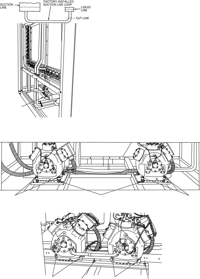
FACTORY-
INSTALLED
SUCTION
LINE LOOP
Fig. 9A Ð Typical Module with Cover Panels Removed
SHIPMENT BOLTS
Fig. 9B Ð Field-Installed Suction Line Loop
38AH044-084,124,134
MOUNTING SPRINGS |
SHIPMENT BOLTS |
38AH094,104
MOUNTING |
RAIL BOLT (3) (2 SHOWN) |
MOUNTING |
|
BOLTS |
BOLTS |
RAIL BOLT (3) (2 SHOWN) |
Fig. 10 Ð Outer View, Compressor Mounting
13
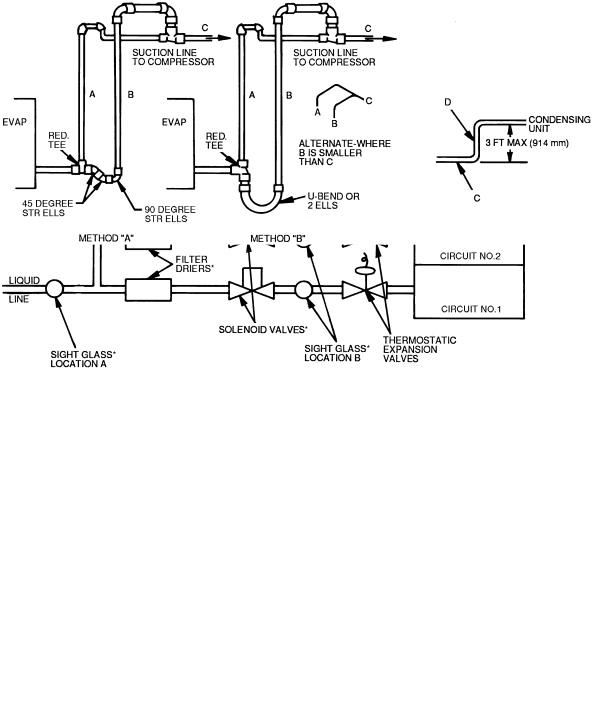
Step 3 Ð Make Refrigerant Piping
Connections
The ®eld-supplied liquid line solenoid valve must be installed at the evaporator to avoid possible compressor damage during unit operation. See Fig. 11 (for 38AH044084 dual-circuit and 38AH094-134 units), or Fig. 12 (for 38AH044-084 optional single-circuit units).
The units have large suction lines to minimize friction losses. The units also have the ability to operate at low capacity. Because of these capabilities, use special care with suction piping and suction risers to ensure proper compressor oil return under all operating conditions. Maximum allowable vertical separation between the condensing unit and the evaporator is shown in Table 5. Size suction lines in accordance with Tables 6A or 6B through 9A or 9B and Fig. 13. Mount liquid line solenoid valve just ahead of the TXVs (thermostatic expansion valves) which will be mounted at the evaporator. See Fig. 11 (for 38AH044-084 dual-circuit and 38AH094-134 units) or Fig. 12 (for 38AH044-084 optional single-circuit units).
To achieve good mixing of the refrigerant leaving the evaporator suction header for proper sensing by the TXV bulb:
1.Install a minimum of two 90-degree elbows upstream of the TXV bulb location. See Fig. 14 (for 38AH044-084 dual-circuit and 38AH094-134 units) or Fig. 15 (for 38AH044-084 optional single-circuit units).
2.Locate the TXV bulb on a vertical riser, where possible. If a horizontal location is necessary, secure the bulb at approximately the 4 o'clock position.
3.Size the suction line from the evaporator to the common suction line to achieve high refrigerant velocity. See Tables 6A or 6B through 9A or 9B and Fig. 13.
If an oil return connection at the bottom of the suction header is supplied with an evaporator, tee-in this connection ahead of ®rst mixing elbow. See Fig. 14 (for 38AH044-084 dual-circuit and 38AH094-134 units) or Fig. 15 (for 38AH044084 optional single-circuit units). When the compressor is below the evaporator, the riser at the evaporator should extend to the top of the evaporator section. After the riser is installed, the suction line can elbow down immediately.
Install a ®eld-supplied ®lter drier and sight glasses in each refrigerant system. Select the ®lter drier for maximum unit capacity and minimum pressure drop. Figure 11 (for 38AH044084 dual-circuit and 38AH094-134 units) or Fig. 12 (for
38AH044-084 optional single-circuit units) shows required location of solenoid valves and recommended locations for the ®lter driers and sight glasses. Complete the refrigerant piping from the evaporator to the condenser before opening the liquid and suction lines at the condenser.
Table 5 Ð Liquid Lift
UNIT |
|
|
MAXIMUM LIQUID LIFT |
|
||
|
60 Hz |
50 Hz |
|
|||
38AH |
|
|
||||
|
Ft |
|
M |
Ft |
|
M |
044 |
69 |
|
21.0 |
57.5 |
|
17.5 |
054 |
75 |
|
23.0 |
75.0 |
|
23.0 |
064 |
75 |
|
23.0 |
65.0 |
|
19.8 |
074 |
45 |
|
13.7 |
37.5 |
|
11.4 |
084 |
75 |
|
23.0 |
75.0 |
|
23.0 |
094 |
55 |
|
16.7 |
46.0 |
|
14.0 |
104 |
50 |
|
15.2 |
42.0 |
|
12.8 |
124 |
75 |
|
23.0 |
65.0 |
|
19.8 |
134 |
45 |
|
13.7 |
37.5 |
|
11.4 |
UNITS 38AH044-084 Ð Relieve the pressure caused by the holding charge into a refrigerant recovery system. Uncap the suction line and cut the run-around tube at the liquid line as close to the loop elbow as possible. This will leave approximately 2 in. (50 mm) of straight tube for liquid line connection.
IMPORTANT: Protect the liquid valves from the heat of brazing.
Leak test the entire system by using soap bubbles and nitrogen or R-22 with an electronic leak detector.
Purge nitrogen or reclaim R-22 from system after completion of leak-checking procedure. Repair leak if one is found. When ®nished, evacuate and dehydrate system using the methods described in Carrier GTAC II (General Training Air Conditioning II), Module 4, System Dehydration.
UNITS 38AH094-134 Ð Relieve the R-22 holding charge of each circuit into a refrigerant recovery system. Remove the liquid line to factory-installed suction line loop by cutting the loop at the liquid valve. (See Fig. 9A and 9B.) Cut as close to the 90-degree bend in the loop as possible. The remaining tube piece in the valve will be used for brazing the liquid line. Unbraze and remove the cap from the liquid line. For 38AH094 and 104 units, sweat-connect the liquid and suction lines from the evaporator. For 38AH124 and 134 units, see Piping Kit Connections on page 21.
LEGEND
LLS Ð Liquid Line Solenoid
TXV Ð Thermostatic Expansion Valve *Field-Supplied.
Fig. 11 Ð Required Location of Solenoid Valves and Recommended Filter Drier and Sight Glass Locations for 38AH044-084 Dual-Circuit and 38AH094-134 Units
14
*Field-Supplied.
Fig. 12 Ð Required Location of Solenoid Valves and Recommended Filter Drier and Sight Glass Locations for 38AH044-084 Optional Single-Circuit Units
|
LEGEND |
|
|
|
|
PIPE D DIAMETER |
|
|||
A |
Ð Pipe A, Suction Riser, without Trap |
|
|
|
|
|
||||
UNIT |
|
|
Dual Circuit* |
|
|
|
|
|||
B |
Ð Pipe B, Suction Riser with Trap |
|
|
|
|
Single Circuit* |
||||
C |
Ð Suction Line to Condensing Unit |
38AH |
A |
|
|
B |
|
|
||
D |
Ð Pipe D, Suction Riser Short Lift |
|
in. |
|
mm |
in. |
|
mm |
in. |
mm |
RED. Ð Reducer |
|
|
|
|
|
|
|
|
|
|
044 |
15¤8 |
|
41 |
15¤8 |
|
41 |
21¤8 |
54 |
||
STR Ð Street |
|
|
||||||||
054 |
15¤8 |
|
41 |
15¤8 |
|
41 |
21¤8 |
54 |
||
NOTES: |
|
|
||||||||
064 |
15¤8 |
|
41 |
21¤8 |
|
54 |
21¤8 |
54 |
||
1. |
Short riser, pipe D, is used when routing suction line to condens- |
074 |
21¤8 |
|
54 |
21¤8 |
|
54 |
21¤8 |
54 |
|
ing unit connection. See table at right. |
084 |
21¤8 |
|
54 |
21¤8 |
|
54 |
25¤8² |
67² |
2. See Tables 6A-9B for values of A, B, and C. |
094, 104 |
21¤8 |
|
54 |
21¤8 |
|
54 |
Ð |
Ð |
|
|
|
124, 134 |
25¤8 |
|
67 |
25¤8 |
|
67 |
Ð |
Ð |
*Maximum length of riser is 3 ft (914 mm).
²Double suction riser required if accessory unloader is ®eld installed.
Fig. 13 Ð Double Suction Riser Construction
15

Table 6A Ð Refrigerant Piping Requirements Ð 38AH044-104 Dual-Circuit Units Ð 60 Hz
|
|
|
|
|
|
|
TOTAL LINEAR LENGTH OF INTERCONNECTING PIPE Ð FT (M) |
|
|
|
||||||||||
|
UNIT |
|
15-25 |
|
25-50 |
|
50-75 |
|
75-100 |
|
100-150 |
|
150-200 |
|||||||
|
38AH |
(4.6-7.6) |
(7.6-15.2) |
(15.2-22.9) |
(22.9-30.5) |
(30.5-45.7) |
(45.7-61.0) |
|||||||||||||
|
|
|
L |
|
S |
L |
|
S |
L |
|
S |
L |
|
S |
L |
|
S |
L |
|
S |
044 |
|
Ckt A |
5¤8 |
|
15¤8 |
7¤8 |
|
15¤8 |
7¤8 |
|
21¤8 |
7¤8 |
|
21¤8 |
7¤8 |
|
21¤8 |
7¤8 |
|
21¤8 |
|
Ckt B |
5¤8 |
|
15¤8 |
7¤8 |
|
15¤8 |
7¤8 |
|
21¤8 |
7¤8 |
|
21¤8 |
7¤8 |
|
21¤8 |
7¤8 |
|
21¤8 |
|
|
|
|
|
|
|
|
|
|||||||||||||
054 |
|
Ckt A |
5¤8 |
|
15¤8 |
7¤8 |
|
15¤8 |
7¤8 |
|
21¤8 |
7¤8 |
|
21¤8 |
7¤8 |
|
21¤8 |
7¤8 |
|
21¤8 |
|
Ckt B |
7¤8 |
|
15¤8 |
7¤8 |
|
21¤8 |
7¤8 |
|
21¤8 |
11¤8 |
|
21¤8 |
11¤8 |
|
21¤8 |
11¤8 |
|
25¤8* |
|
|
|
|
|
|
|
|
|
|||||||||||||
064 |
|
Ckt A |
7¤8 |
|
15¤8 |
7¤8 |
|
21¤8 |
7¤8 |
|
21¤8 |
7¤8 |
|
21¤8 |
11¤8 |
|
21¤8 |
11¤8 |
|
25¤8² |
|
Ckt B |
7¤8 |
|
21¤8 |
7¤8 |
|
21¤8 |
7¤8 |
|
21¤8 |
11¤8 |
|
21¤8 |
11¤8 |
|
25¤8 |
11¤8 |
|
25¤8 |
|
|
|
|
|
|
|
|
|
|||||||||||||
074 |
|
Ckt A |
7¤8 |
|
21¤8 |
7¤8 |
|
21¤8 |
7¤8 |
|
21¤8 |
11¤8 |
|
21¤8 |
11¤8 |
|
25¤8² |
1 1¤8 |
|
25¤8² |
|
Ckt B |
7¤8 |
|
21¤8 |
11¤8 |
|
21¤8 |
11¤8 |
|
21¤8 |
11¤8 |
|
25¤8 |
13¤8 |
|
25¤8 |
13¤8 |
|
25¤8 |
|
|
|
|
|
|
|
|
|
|||||||||||||
084 |
|
Ckt A |
7¤8 |
|
21¤8 |
11¤8 |
|
21¤8 |
11¤8 |
|
21¤8 |
11¤8 |
|
25¤8² |
1 3¤8 |
|
25¤8² |
1 3¤8 |
|
25¤8² |
|
Ckt B |
7¤8 |
|
21¤8 |
11¤8 |
|
21¤8 |
11¤8 |
|
21¤8 |
11¤8 |
|
25¤8 |
13¤8 |
|
25¤8 |
13¤8 |
|
25¤8 |
|
|
|
|
|
|
|
|
|
|||||||||||||
094 |
|
Ckt A |
7¤8 |
|
21¤8 |
11¤8 |
|
21¤8 |
11¤8 |
|
25¤8² |
1 1¤8 |
|
25¤8² |
1 3¤8 |
|
25¤8² |
1 3¤8 |
|
31¤8** |
|
Ckt B |
7¤8 |
|
21¤8 |
7¤8 |
|
21¤8 |
11¤8 |
|
21¤8 |
11¤8 |
|
25¤8 |
11¤8 |
|
25¤8 |
13¤8 |
|
25¤8 |
|
|
|
|
|
|
|
|
|
|||||||||||||
104 |
|
Ckt A |
7¤8 |
|
21¤8 |
11¤8 |
|
21¤8 |
11¤8 |
|
25¤8² |
1 1¤8 |
|
25¤8² |
1 3¤8 |
|
25¤8² |
1 3¤8 |
|
31¤8** |
|
Ckt B |
7¤8 |
|
21¤8 |
11¤8 |
|
21¤8 |
11¤8 |
|
25¤8 |
11¤8 |
|
25¤8 |
13¤8 |
|
31¤8** |
13¤8 |
|
31¤8** |
|
|
|
|
|
|
|
|
|
|||||||||||||
LEGEND
L Ð Liquid Line
S Ð Suction Line
*Double suction riser required on units with ®eld installed unloader on circuit B compressor if condensing unit is elevated above evaporator.
²Double suction riser required on units with ®eld installed unloader on circuit B compressor if condensing unit is elevated above evaporator.
**Double suction riser required on all unit con®gurations if condensing unit is elevated above evaporator.
NOTES:
1.Addition of 2 unloaders to circuit B compressor is not recommended.
2.38AH094 and 38AH104 piping sizes apply only to factory supplied unit con®gurations. They do NOT take into account any ®eld installed unloaders.
3.Piping sizes are based on unit operation above 40 F (4.4 C) saturated suction temperature (SST). When operating below 40 F (4.4 C), refer to Carrier System Design Manual, E20-IIT piping design program, or ASHRAE Handbook to select proper line sizes.
4.Pipe sizes are based on the total linear length shown for each column, plus a 50% allowance for ®ttings.
5.Suction and liquid line sizing is based on pressure drop equivalent to 2 F (1.1 C) at nominal rating conditions. Higher pressure drop design criteria may allow selection of smaller pipe sizes, but at a penalty of decreased system capacity and ef®ciency.
6.Double suction risers may be required if condensing unit is elevated above the evaporator. See footnotes and double suction riser table below.
7.Refer to Carrier System Design Manual or to E20-II design programs for further information on selecting pipe sizes for split systems.
8.All pipe sizes are OD inches. Equivalent sizes in millimeters follow:
in. |
mm |
5¤8 |
15.9 |
7¤8 |
22.2 |
11¤8 |
28.6 |
13¤8 |
34.9 |
15¤8 |
41.3 |
21¤8 |
54.0 |
25¤8 |
66.7 |
31¤8 |
79.4 |
Table 6B Ð Refrigerant Piping Requirements for Double Suction Risers, 38AH054-104 Dual-Circuit Units Ð 60 Hz
|
|
|
|
|
|
TOTAL LINEAR LENGTH OF INTERCONNECTING PIPE Ð FT (M) |
|
|
|
|||||||||||
|
UNIT |
|
50-75 |
|
|
|
|
75-100 |
|
|
|
100-150 |
|
|
150-200 |
|
||||
|
38AH |
|
(15.2-22.9) |
|
|
(22.9-30.5) |
|
|
(30.5-45.7) |
|
|
(45.7-61.0) |
|
|||||||
|
|
|
A |
|
B |
C |
A |
|
|
B |
|
C |
A |
|
B |
C |
A |
|
B |
C |
054 |
|
Ckt A |
Ð |
|
Ð |
Ð |
Ð |
|
Ð |
Ð |
|
Ð |
Ð |
|
Ð |
Ð |
Ð |
|
Ð |
|
|
Ckt B |
Ð |
|
Ð |
Ð |
Ð |
|
Ð |
Ð |
|
Ð |
Ð |
|
Ð |
1 |
5¤8 |
|
21¤8 |
25¤8 |
|
|
|
|
|
|
|
|
||||||||||||||
064 |
|
Ckt A |
Ð |
|
Ð |
Ð |
Ð |
|
Ð |
Ð |
|
Ð |
Ð |
|
Ð |
1 |
5¤8 |
|
21¤8 |
25¤8 |
|
Ckt B |
Ð |
|
Ð |
Ð |
Ð |
|
Ð |
Ð |
|
Ð |
Ð |
|
Ð |
Ð |
Ð |
|
Ð |
|
|
|
|
|
|
|
|
|
|
|||||||||||||
074 |
|
Ckt A |
Ð |
|
Ð |
Ð |
Ð |
|
Ð |
Ð |
|
1 |
5¤8 |
|
21¤8 |
25¤8 |
15¤8 |
|
21¤8 |
25¤8 |
|
Ckt B |
Ð |
|
Ð |
Ð |
Ð |
|
Ð |
Ð |
|
Ð |
Ð |
|
Ð |
Ð |
Ð |
|
Ð |
|
|
|
|
|
|
|
|
|
|
|||||||||||||
084 |
|
Ckt A |
Ð |
|
Ð |
Ð |
1 5¤8 |
|
|
21¤8 |
|
25¤8 |
15¤8 |
|
21¤8 |
25¤8 |
15¤8 |
|
21¤8 |
25¤8 |
|
Ckt B |
Ð |
|
Ð |
Ð |
Ð |
|
Ð |
Ð |
|
Ð |
Ð |
|
Ð |
Ð |
Ð |
|
Ð |
|
|
|
|
|
|
|
|
|
|
|||||||||||||
094 |
|
Ckt A |
15¤8 |
|
21¤8 |
25¤8 |
15¤8 |
|
|
21¤8 |
|
25¤8 |
15¤8 |
|
21¤8 |
25¤8 |
15¤8 |
|
25¤8 |
31¤8 |
|
Ckt B |
Ð |
|
Ð |
Ð |
Ð |
|
Ð |
Ð |
|
Ð |
Ð |
|
Ð |
Ð |
Ð |
|
Ð |
|
|
|
|
|
|
|
|
|
|
|||||||||||||
104 |
|
Ckt A |
13¤8 |
|
21¤8 |
25¤8 |
13¤8 |
|
|
21¤8 |
|
25¤8 |
13¤8 |
|
21¤8 |
25¤8 |
15¤8 |
|
25¤8 |
31¤8 |
|
Ckt B |
Ð |
|
Ð |
Ð |
Ð |
|
Ð |
Ð |
|
1 |
3¤8 |
|
25¤8 |
31¤8 |
15¤8 |
|
25¤8 |
31¤8 |
|
|
|
|
|
|
|
|
||||||||||||||
LEGEND
ÐÐ Not Required
Pipe A Ð Suction Riser Without Trap
Pipe B Ð Suction Riser With Trap
Pipe C Ð Suction Line to Condensing Unit
NOTES:
1.See Refrigerant Piping Requirements table at top of page to determine need for double suction risers.
2.Pipe sizes are based on the total linear length, shown for each column, plus a 50% allowance for ®ttings.
3.Suction and liquid line sizing is based on pressure drop equivalent to 2 F (1.1 C) at nominal rating conditions. Higher design pressure drop criteria may allow selection of smaller pipe sizes but at a penalty of decreased system capacity and ef®ciency.
4.Refer to Carrier System Design Manual or to E20-II design programs for further information on selecting pipe sizes for split systems.
5.All pipe sizes are OD inches. See Table 6A notes for metric equivalents.
6.Refer to Fig. 13 for double suction riser construction.
16

Table 7A Ð Refrigerant Piping Requirements, 38AH044-104 Dual-Circuit Units Ð 50 Hz
|
|
|
|
|
|
|
|
TOTAL LINEAR LENGTH OF INTERCONNECTING PIPE Ð FT (M) |
|
|
|
|||||||||
|
UNIT |
|
15-25 |
|
25-50 |
|
50-75 |
|
75-100 |
|
100-150 |
|
150-200 |
|||||||
|
38AH |
(4.6-7.6) |
(7.6-15.2) |
(15.2-22.9) |
(22.9-30.5) |
(30.5-45.7) |
(45.7-61.0) |
|||||||||||||
|
|
|
L |
|
S |
L |
|
S |
L |
|
S |
L |
|
S |
L |
|
S |
L |
|
S |
044 |
|
Ckt A |
5¤8 |
|
13¤8 |
7¤8 |
|
15¤8 |
7¤8 |
|
15¤8 |
7¤8 |
|
21¤8 |
7¤8 |
|
21¤8 |
7¤8 |
|
21¤8 |
|
Ckt B |
5¤8 |
|
13¤8 |
7¤8 |
|
15¤8 |
7¤8 |
|
15¤8 |
7¤8 |
|
21¤8 |
7¤8 |
|
21¤8 |
7¤8 |
|
21¤8 |
|
|
|
|
|
|
|
|
|
|||||||||||||
054 |
|
Ckt A |
5¤8 |
|
13¤8 |
7¤8 |
|
15¤8 |
7¤8 |
|
15¤8 |
7¤8 |
|
21¤8 |
7¤8 |
|
21¤8 |
7¤8 |
|
21¤8 |
|
Ckt B |
7¤8 |
|
15¤8 |
7¤8 |
|
15¤8 |
7¤8 |
|
21¤8 |
7¤8 |
|
21¤8 |
11¤8 |
|
21¤8 |
11¤8 |
|
25¤8*² |
|
|
|
|
|
|
|
|
|
|||||||||||||
064 |
|
Ckt A |
7¤8 |
|
15¤8 |
7¤8 |
|
15¤8 |
7¤8 |
|
21¤8² |
7¤8 |
|
21¤8² |
1 1¤8 |
|
21¤8² |
1 1¤8 |
|
25¤8** |
|
Ckt B |
7¤8 |
|
15¤8 |
7¤8 |
|
21¤8 |
7¤8 |
|
21¤8 |
7¤8 |
|
21¤8 |
11¤8 |
|
25¤8* |
11¤8 |
|
25¤8* |
|
|
|
|
|
|
|
|
|
|||||||||||||
074 |
|
Ckt A |
7¤8 |
|
15¤8 |
7¤8 |
|
21¤8 |
7¤8 |
|
21¤8 |
7¤8 |
|
21¤8 |
11¤8 |
|
25¤8² |
1 1¤8 |
|
25¤8² |
|
Ckt B |
7¤8 |
|
21¤8 |
7¤8 |
|
21¤8 |
11¤8 |
|
21¤8 |
11¤8 |
|
25¤8 |
11¤8 |
|
25¤8 |
11¤8 |
|
25¤8 |
|
|
|
|
|
|
|
|
|
|||||||||||||
084 |
|
Ckt A |
7¤8 |
|
21¤8 |
7¤8 |
|
21¤8 |
11¤8 |
|
21¤8 |
11¤8 |
|
25¤8² |
1 1¤8 |
|
25¤8² |
1 1¤8 |
|
25¤8² |
|
Ckt B |
7¤8 |
|
21¤8 |
7¤8 |
|
21¤8 |
11¤8 |
|
21¤8 |
11¤8 |
|
25¤8 |
11¤8 |
|
25¤8 |
11¤8 |
|
25¤8 |
|
|
|
|
|
|
|
|
|
|||||||||||||
094 |
|
Ckt A |
7¤8 |
|
21¤8 |
11¤8 |
|
21¤8 |
11¤8 |
|
25¤8** |
11¤8 |
|
25¤8** |
11¤8 |
|
25¤8** |
13¤8 |
|
31¤8** |
|
Ckt B |
7¤8 |
|
21¤8 |
7¤8 |
|
21¤8 |
11¤8 |
|
21¤8 |
11¤8 |
|
25¤8*² |
1 1¤8 |
|
25¤8*² |
1 1¤8 |
|
25¤8*² |
|
|
|
|
|
|
|
|
|
|||||||||||||
104 |
|
Ckt A |
7¤8 |
|
21¤8 |
7¤8 |
|
21¤8 |
11¤8 |
|
21¤8 |
11¤8 |
|
25¤8** |
11¤8 |
|
25¤8** |
13¤8 |
|
31¤8** |
|
Ckt B |
7¤8 |
|
21¤8 |
11¤8 |
|
21¤8 |
11¤8 |
|
25¤8 |
11¤8 |
|
25¤8 |
13¤8 |
|
25¤8 |
13¤8 |
|
31¤8** |
|
|
|
|
|
|
|
|
|
|||||||||||||
LEGEND
L Ð Liquid Line
S Ð Suction Line
*Double suction riser required on units with ®eld installed unloader on circuit B compressor if condensing unit is elevated above evaporator.
²Double suction riser required on units with ®eld installed unloader on circuit B compressor if condensing unit is elevated above evaporator.
**Double suction riser required on all unit con®gurations if condensing unit is elevated above evaporator.
NOTES:
1.Addition of 2 unloaders to circuit B compressor is not recommended.
2.38AH094 and 38AH104 piping sizes apply only to factory supplied unit con®gurations. They do NOT take into account any ®eld installed unloaders.
3.Piping sizes are based on unit operation above 40 F (4.4 C) saturated suction temperature (SST). When operating below 40 F (4.4 C), refer to Carrier System Design Manual, E20-IIT piping design program, or ASHRAE Handbook to select proper line sizes.
4.Pipe sizes are based on the total linear length shown for each column, plus a 50% allowance for ®ttings.
5.Suction and liquid line sizing is based on pressure drop equivalent to 2 F (1.1 C) at nominal rating conditions. Higher pressure drop design criteria may allow selection of smaller pipe sizes, but at a penalty of decreased system capacity and ef®ciency.
6.Double suction risers may be required if condensing unit is elevated above the evaporator. See footnotes and double suction riser table below.
7.Refer to Carrier System Design Manual or to E20-II design programs for further information on selecting pipe sizes for split systems.
8.All pipe sizes are OD inches. Equivalent sizes in millimeters follow:
in. |
mm |
5¤8 |
15.9 |
7¤8 |
22.2 |
11¤8 |
28.6 |
13¤8 |
34.9 |
15¤8 |
41.3 |
21¤8 |
54.0 |
25¤8 |
66.7 |
31¤8 |
79.4 |
Table 7BÐ Refrigerant Piping Requirements for Double Suction Risers, 38AH054-104 Dual-Circuit Units Ð 50 Hz
|
|
|
|
|
|
TOTAL LINEAR LENGTH OF INTERCONNECTING PIPE Ð FT (M) |
|
|
|
||||||||||||
|
UNIT |
|
50-75 |
|
|
|
|
|
75-100 |
|
|
|
100-150 |
|
|
150-200 |
|
||||
|
38AH |
|
(15.2-22.9) |
|
|
|
(22.9-30.5) |
|
|
(30.5-45.7) |
|
|
(45.7-61.0) |
|
|||||||
|
|
|
A |
|
B |
C |
|
A |
|
|
B |
|
C |
A |
|
B |
C |
A |
|
B |
C |
054 |
|
Ckt A |
Ð |
|
Ð |
Ð |
Ð |
|
|
Ð |
Ð |
|
Ð |
Ð |
|
Ð |
Ð |
Ð |
|
Ð |
|
|
Ckt B |
Ð |
|
Ð |
Ð |
Ð |
|
|
Ð |
Ð |
|
Ð |
Ð |
|
Ð |
1 |
5¤8 |
|
21¤8 |
25¤8 |
|
|
|
|
|
|
|
|
|
||||||||||||||
064 |
|
Ckt A |
13¤8 |
|
15¤8 |
21¤8 |
|
13¤8 |
|
|
15¤8 |
|
21¤8 |
15¤8 |
|
15¤8 |
21¤8 |
15¤8 |
|
21¤8 |
25¤8 |
|
Ckt B |
Ð |
|
Ð |
Ð |
Ð |
|
|
Ð |
Ð |
|
1 |
5¤8 |
|
21¤8 |
25¤8 |
15¤8 |
|
21¤8 |
25¤8 |
|
|
|
|
|
|
|
|
|
||||||||||||||
074 |
|
Ckt A |
Ð |
|
Ð |
Ð |
Ð |
|
|
Ð |
Ð |
|
1 |
5¤8 |
|
21¤8 |
25¤8 |
15¤8 |
|
21¤8 |
25¤8 |
|
Ckt B |
Ð |
|
Ð |
Ð |
Ð |
|
|
Ð |
Ð |
|
Ð |
Ð |
|
Ð |
Ð |
Ð |
|
Ð |
|
|
|
|
|
|
|
|
|
|
|
|||||||||||||
084 |
|
Ckt A |
Ð |
|
Ð |
Ð |
1 |
5¤8 |
|
|
21¤8 |
|
25¤8 |
15¤8 |
|
21¤8 |
25¤8 |
15¤8 |
|
21¤8 |
25¤8 |
|
Ckt B |
Ð |
|
Ð |
Ð |
Ð |
|
|
Ð |
Ð |
|
Ð |
Ð |
|
Ð |
Ð |
Ð |
|
Ð |
|
|
|
|
|
|
|
|
|
|
|
|||||||||||||
094 |
|
Ckt A |
13¤8 |
|
21¤8 |
25¤8 |
|
13¤8 |
|
|
21¤8 |
|
25¤8 |
15¤8 |
|
21¤8 |
25¤8 |
15¤8 |
|
25¤8 |
31¤8 |
|
Ckt B |
Ð |
|
Ð |
Ð |
1 |
3¤8 |
|
|
21¤8 |
|
25¤8 |
15¤8 |
|
21¤8 |
25¤8 |
15¤8 |
|
21¤8 |
25¤8 |
|
|
|
|
|
|
|
|
|
||||||||||||||
104 |
|
Ckt A |
Ð |
|
Ð |
Ð |
1 |
3¤8 |
|
|
21¤8 |
|
25¤8 |
15¤8 |
|
21¤8 |
25¤8 |
15¤8 |
|
25¤8 |
31¤8 |
|
Ckt B |
Ð |
|
Ð |
Ð |
Ð |
|
|
Ð |
Ð |
|
Ð |
Ð |
|
Ð |
1 |
5¤8 |
|
25¤8 |
31¤8 |
|
|
|
|
|
|
|
|
|
||||||||||||||
LEGEND
ÐÐ Not Required
Pipe A Ð Suction Riser Without Trap
Pipe B Ð Suction Riser With Trap
Pipe C Ð Suction Line to Condensing Unit
NOTES:
1.See Refrigerant Piping Requirements table at top of page to determine need for double suction risers.
2.Pipe sizes are based on the total linear length, shown for each column, plus a 50% allowance for ®ttings.
3.Suction and liquid line sizing is based on pressure drop equivalent to 2 F (1.1 C) at nominal rating conditions. Higher design pressure drop criteria may allow selection of smaller pipe sizes but at a penalty of decreased system capacity and ef®ciency.
4.Refer to Carrier System Design Manual or to E20-II design programs for further information on selecting pipe sizes for split systems.
5.All pipe sizes are OD inches. See Table 7A notes for metric equivalents.
6.Refer to Fig. 13 for double suction riser construction.
17
 Loading...