


 Loading...
38AUM Air Cooled Condensing Units – 50Hz
Quality Assurance
Certificate Reg. No: 04 100 950420
Subject to change without notice |
Installation Operation Maintenance Manual |
Manufacturer’s Name: Saudi Airconditioning Manufacturing Co. Ltd. |
|
Country of origin : Jeddah, Saudi Arabia |
|
Nearest port of embarkation: Jeddah Islamic port |
|
Product classification: Commercial and Residential |
|
38AUM Air Cooled Condensing Units – 50Hz
Nominal Cooling Capacity 6.0 – 15.0 Tons
HFC R-410A Refrigerant
The 38AUM series outdoor air cooled condensing units matched with Carrier’s 40RUM series indoor air handler’s offer a wide variety of options for your HVAC application needs. Whether it’s first cost with the 38AUM single compressor models or superior part load performance from the two compressor models, this series is designed for long, dependable operation as a rooftop or on-the-ground installation. All 38AUM and 40RUM series units use environmentally sound Puron ® R-410A refrigerant. Together, they create a reliable split system that provides easy solutions to a wide range of commercial HVAC needs.
Contact your local Carrier representative for additional reference materials.
Page 1
Table of Contents |
|
Safety Considerations ................................................................................................................................................. |
2 |
Unit Physical Data ....................................................................................................................................................... |
4 |
Base Unit Dimensions ................................................................................................................................................. |
5 |
Installation Guideline ................................................................................................................................................... |
7 |
Pre-Start-Up/Start-Up/Operating Sequence.............................................................................................................. |
19 |
Routine System Maintenance/Service ...................................................................................................................... |
23 |
Piping Recommendation ........................................................................................................................................... |
30 |
Electrical Data Table ................................................................................................................................................. |
31 |
Typical Wiring Schematic .......................................................................................................................................... |
32 |
Charging Chart .......................................................................................................................................................... |
35 |
R-410A Refrigerant Quick Reference Guide............................................................................................................. |
39 |
Air Conditioner Troubleshooting Chart...................................................................................................................... |
40 |
Mandatory Startup Checklist and Record ................................................................................................................. |
41 |
SAFETY CONSIDERATIONS |
|
General |
|
Improper installation, adjustment, alteration, service, maintenance or use can cause explosion, fire, electrical shock or other conditions which may cause personal injury or property damage. Consult a qualified installer; service agency must use factory-authorized kits or accessories when modifying this product. Refer to the individual instructions packaged with the kits or accessories when installing.
Follow all the safety codes. Wear safety glasses and work gloves. Use quenching cloths for brazing operations and have a fire extinguisher available. Read these instructions thoroughly and follow all warnings or cautions attached to the unit. Consult local building codes for special requirements. In absence of local codes, it is recommended that the USA standard ANSI/NFPA 70, National Electrical Code (NEC), be followed.
It is important to recognize safety information. This is the safety-alert symbol  . When you see this symbol on the unit and in instructions or manuals, be alert to the potential for personal injury.
Understand the signal words DANGER, WARNING, CAUTION, and NOTE. These words are used with the safetyalert symbol. DANGER identifies the most serious hazards which will result in severe personal injury of death. WARNING signifies hazards which could result in personal injury or death. CAUTION is used to identify unsafe practices, which may result in minor personal injury or product and property damage. NOTE is used to highlight suggestions which will result in enhanced installation, reliability, or operation.
Installation Safety Considerations
After the unit has been received and when it is ready to be installed or reinstalled, it must be inspected for damage. If damage is detected upon receipt, immediately file a claim with the shipping company or repair.
This machine must be installed in a location that is not accessible to the public and protected against access by non-authorized people. This machine must not be installed in an explosive atmosphere.
Do not remove the skid or the packaging until the unit is in its final position. The units can also be lifted with slings, using only the designated lifting points marked on the unit (labels on the chassis and a label with all unit handling instructions are attached to the unit). Use slings with the correct capacity, and always follow the lifting instructions on the certified drawings supplied for the unit.
Safety is only guaranteed, if these instructions are carefully followed. If this is not the case, there is a risk of material deterioration and injuries to personnel. These units are not designed to be lifted from above.
Warranty
Warranty is based on the general terms and conditions of the manufacturer. Any modifications to the design and/or installation made without discussion with Carrier and without advance written agreement will result in the loss of the right to any warranty claims and any claim for injury to personnel as a result of these modifications.
Page 2


 WARNING
ELECTRIC SHOCK HAZARD
Failure to follow this warning could cause personal injury or death.
Before performing service or maintenance operations on unit, always turn off main power switch to unit and install lockout tag. Unit may have more than one power switch.

 CAUTION
CUT HAZARD
Failure to follow this warning could cause personal injury.
Sheet metal parts may have sharp edges or burrs. Use care and wear appropriate protective clothing, safety glasses and gloves when handling parts and servicing air conditioning equipment

 WARNING
UNIT OPERATION AND SAFETY
HAZARD
Failure to follow this warning could cause personal injury, death and /or equipment damage.
Puron® (R-410A) refrigerant systems operate at higher pressures than standard R-22 systems. Do not use R-22 service equipment or components on Puron® refrigerant equipment.

 WARNING
PERSONAL SAFETY AND ENVIRONMENTAL
HAZARD
Failure to follow this warning could cause personal injury or death damage.
Relieve pressure and recover all refrigerant before system repair or final unit disposal. Wear safety glasses and gloves when handling refrigerants. Keep torches and other ignition sources away from refrigerants and oils.
Page 3
UNIT PHYSICAL DATA (ENGLISH UNITS)
Unit 38AUM |
Z07 |
|
Z08 |
|
D12 |
D14 |
D16 |
Refrigeration System |
|
|
|
|
Puron ® |
|
|
No. of Ckt / No. of Comp. / Type |
1 / 1 / Scroll |
|
|
|
2 / 2 / Scroll |
|
|
Initial Charge per Circuit (Ib) |
7.72 |
|
8.16 |
|
7.05 / 7.05 |
9.03 / 9.70 |
12.57 / 11.57 |
Operating Charge per Circuit (Ib) |
12.79 |
|
13.67 |
|
11.66 / 11.66 |
15.41 / 16.29 |
20.94 / 19.29 |
Metering Device |
|
|
|
|
TXV |
|
|
High - Pressure Trip / Reset (PSIG) |
|
|
|
630 / 505 |
|
|
|
Low - Pressure Trip / Reset (PSIG) |
|
|
|
54 / 117 |
|
|
|
Condenser Coil |
|
|
RTPF - Round Tube / Plate Fin Coil Design |
|
|||
Material (Fin / Tube) |
|
|
|
|
Al/Cu |
|
|
Fin Type |
|
|
|
|
Double Wavy |
|
|
Rows / FPI |
|
|
2 / 17 |
|
|
3 / 17 |
2 / 17 |
Total Face Area (ft²) |
17.5 |
|
|
25.1 |
31.8 |
23.5 x 2 |
|
Condenser Fan & Motor |
|
|
|
|
|
|
|
Qty. / Motor Drive Type |
|
|
|
|
2 / Direct |
|
|
Motor HP / RPM |
|
|
|
1/3 / 1200 |
|
1/2 / 860 |
|
Fan Diameter (mm) |
|
|
|
559 |
|
660 |
|
UNIT PHYSICAL DATA (SI UNITS)
Unit 38AUM |
Z07 |
|
Z08 |
|
D12 |
D14 |
D16 |
Refrigeration System |
|
|
|
|
Puron ® |
|
|
No. of Ckt / No. of Comp. / Type |
1 / 1 / Scroll |
|
|
|
2 / 2 / Scroll |
|
|
Initial Charge per Circuit (kg) |
3.50 |
|
3.70 |
|
3.20 / 3.20 |
4.10 / 4.40 |
5.70 / 5.25 |
Operating Charge per Circuit (kg) |
5.80 |
|
6.20 |
|
5.29 / 5.29 |
6.99 / 7.39 |
9.50 / 8.75 |
Metering Device |
|
|
|
|
TXV |
|
|
High - Pressure Trip / Reset (PSIG) |
|
|
|
630 / 505 |
|
|
|
Low - Pressure Trip / Reset (PSIG) |
|
|
|
54 / 117 |
|
|
|
Condenser Coil |
|
|
RTPF - Round Tube / Plate Fin Coil Design |
|
|||
Material (Fin / Tube) |
|
|
|
|
Al/Cu |
|
|
Fin Type |
|
|
|
|
Double Wavy |
|
|
Rows / FPI |
|
|
2 / 17 |
|
|
3 / 17 |
2 / 17 |
Total Face Area (m²) |
1.63 |
|
|
2.33 |
2.95 |
2.18 x 2 |
|
Condenser Fan & Motor |
|
|
|
|
|
|
|
Qty. / Motor Drive Type |
|
|
|
|
2 / Direct |
|
|
Motor HP / RPM |
|
|
|
1/3 / 1200 |
|
1/2 / 860 |
|
Fan Diameter (in) |
|
|
|
22 |
|
26 |
|
Page 4

BASE UNIT DIMENSIONS – 38AUM Series Size Z07-D14
FRONT VIEW
|
|
|
|
|
|
|
|
|
|
|
|
|
LEFT SIDE VIEW |
|
|
|
|
|
RIGHT SIDE VIEW |
||||
|
|
|
|
|
|
|
|
|
|
|
|
Unit |
Unit |
Height (mm) |
Center of Gravity |
Service Valve |
|||||||
|
(mm) |
|
Connections |
||||||||
Weight |
|
|
|
||||||||
38AUM |
|
|
|
|
|
|
|
|
|
||
(kg) |
H |
X |
Y |
Z |
Suction |
Liquid |
|||||
|
|||||||||||
|
|
|
|
|
|
|
|
|
|
|
|
Z07 |
176.0 |
1165.0 |
457.2 |
609.6 |
533.4 |
1-1/8 |
3/8 |
|
|
|
|
|
|
|
|
|
|
|
|
|
|
|
|
Z08 |
177.0 |
1165.0 |
457.2 |
609.6 |
533.4 |
1-1/8 |
1/2 |
|
|
|
|
|
|
|
|
|
|
|
|
|
|
|
|
D12 |
234.0 |
1368.0 |
482.6 |
584.2 |
609.6 |
1-1/8 |
3/8 |
|
|
|
|
|
|
|
|
|
|
|
|
|
|
|
|
D14 |
297.0 |
1368.0 |
508.0 |
635.0 |
609.6 |
1-3/8 |
1/2 |
|
|
|
|
|
|
|
|
|
|
|
|
|
|
|
|
 - Center Of Gravity
 - Direction of Air Flow
NOTES:
1.Minimum clearance (Local codes or jurisdiction may prevail):
A.Bottom to combustible surfaces: 0 inches
B.Outdoor coil, for proper airflow: 36 inches one side, 12 inches the other. The side getting the greater clearance is optional.
C.Overhead: 60 inches, to assure proper outdoor fan operation.
D.Between units: Control box side: 42 inches per NEC.
E.Between unit and ungrounded surfaces: Control box side, 36 inches per NEC.
F.Between unit and block or concrete walls and other grounded surfaces: Control box side 42 inches per NEC.
2.With exception of the clearance for the outdoor coil as stated in note 1B, are movable fence or barricade requires no clearance.
3.Units may be installed on combustible floors made from wood or Class A, B or C roof covering material.
Page 5

BASE UNIT DIMENSIONS – 38AUM Series Size D16
TOP VIEW
LEFT SIDE VIEW
|
|
|
|
|
|
|
- Center Of Gravity |
|
|
|
|
|
|
|
|
- Direction of Air Flow |
|
|
|
FRONT |
|
|
|
|
|
|
|
|
|
|
|
|
|
|
|
Unit |
Unit |
Height |
Center of Gravity |
Service Valve |
||||
(mm) |
|
(mm) |
|
Connections |
|
|||
38AUM |
Weight (kg) |
H |
X |
Y |
Z |
Suction |
Liquid |
|
|
|
|||||||
|
|
|
|
|
|
|
|
|
D16 |
332.0 |
1339 |
965.2 |
482.6 |
431.8 |
1-3/8 |
1/2 |
|
|
|
|
|
|
|
|
|
|
NOTES:
1.Minimum clearance (Local codes or jurisdiction may prevail):
A.Bottom to combustibles surfaces: 0 Inches
B.Outdoor coil, for proper airflow: 36 inches one side, 12 inches the other. The side getting the greater clearance is optional.
C.Overhead: 60 inches, to assure proper outdoor fan operation.
D.Between units: control box side: 42 inches per NEC.
E.Between unit and ungrounded surfaces: Control box side, 36 inches per NEC.
F.Between unit and block or concrete walls and other grounded surfaces: Control box side 42 inches per NEC.
2.With exception of the clearance for the outdoor coil as stated in note 1B, are movable fence or barricade requires no clearance.
3.Units may be installed on combustible floor made from wood or Class A, B or C roof covering material.
Page 6

INSTALLATION GUIDELINE
Replacement/Retrofit – R-22 to Puron®
Replacement/retrofit installations require change-out of outdoor unit, metering device, and filter driers. Change-out of indoor coil (evaporator) and interconnecting tubing is recommended.
Existing evaporator coil – If the existing evaporator coil may be re-used, check with the coil manufacturer to verify the coil construction is suitable for operation with the higher pressures of Puron® (R-410A). Also determine if the existing TXV valve is compatible with R-410A, replace if necessary. The minimum factory test pressure rating must be 2413 kPa (350 psig). Existing coil will need to be purged with Nitrogen to remove as much mineral oil as possible to eliminate cross contamination of oils.
Acid test – If the existing system is being replaced because of a compressor electrical failure, assume acid is in system. If system is being replaced for any other reason, use an approved acid test kit to determine acid level. If even low levels of acid are detected, install a 100 percent activated alumina suction-line filter drier in addition to the replacement liquid-line filter drier. Remove the suction line filter drier as soon as possible, with a maximum of 72 hr of operation. Recommendation: Install a ball valve in the liquid line at the filter drier location when installing a suction filter in the suction line.
Existing refrigeration piping – Reuse of existing refrigerant piping involves three issues: quality (strength) of existing tubing, cleanliness and tube size. Inspect all tube segments and joints for signs of damage, corrosion or poor brazing. Flush the interconnecting piping system with dry Nitrogen to eliminate as much trace of mineral oil as possible.
Same tube sizes are capable of handling higher flow rates (expressed as tons of cooling capacity) with Puron refrigerant compared to R-22 at constant pressure drops. For example, a 1/2-inch OD liquid line is rated at 33% higher tons with Puron® than with R-22 (at 5°pressure drop). A 1 1/8-inch OD suction line is rated at 53% higher tons with Puron® than with R-22 (at 2° pressure drop). Refrigeration lines selected for R-22 use are typically oversized for Puron® applications. Carefully check the existing suction line size against the table for maximum size (see Table Piping Recommendation); replace vertical riser segments if necessary. Check existing liquid line size against sizing data (see Table Piping Recommendation); replace with smaller lines when feasible.
Installation
1.Remove the existing evaporator coil or fan coil and install the replacement coil when appropriate.
2.Drain oil from low points and traps in suction line tubing (and hot gas bypass tubing if appropriate) and evaporator if they were not replaced. Removing oil from evaporator coil may require purging of the tubing with dry nitrogen.
3.Unless indoor unit is equipped with a Puron® approved metering device, change the metering device to a thermal expansion valve (TXV) designed for Puron® (R-410A).
4.Remove the existing outdoor unit. Install the new outdoor unit according to these installation instructions.
5.Install a new field-supplied liquid-line filter drier at the indoor coil just upstream of the TXV or fix orifice metering device.
6.If a suction line filter drier is also to be installed, install suction line drier downstream of suction line service valve at condensing unit.
 CAUTION
UNIT DAMAGE HAZARD
Failure to follow this caution may result in equipment damage.
Never install suction-line filter drier in the liquid-line of a Puron® system.
7.If required, install a 100% activated alumina suction line filter drier at the outdoor unit.
8.Evacuate and charge the system according to the instructions in this installation manual.
9.Operate the system for 10 hr. Monitor the pressure drop across the suction line filter drier. If pressure drop exceeds 21kPa (3 psig), replace suction-line and liquid-line filter driers. Be sure to purge system with dry nitrogen and evacuate when replacing filter driers. Continue to monitor the pressure drop across suction-line filter drier. Repeat filter changes is necessary. Never leave suction-line filter drier in system longer than 72 hr (actual time).
Page 7
Matching 38AUM Model to Evaporator Coil
The Model 38AUMZ is a single-circuit unit design, requiring one set of refrigeration piping. This model can be connected to an evaporator coil with one circuit or with two circuits (by manifolding the evaporator connections into a single piping system). The Model 38AUMD is a dual-circuit unit design that requires two sets of refrigeration piping between the outdoor unit and the evaporator coil (or coils). This model can only be connected to an evaporator coil that has two refrigeration circuits (or to two separate evaporator coils). The Model 38AUMD CANNOT be connected to a single-circuit evaporator coil. The Model 38AUMD CANNOT be field-converted to a single-circuit design. Before unpacking this new 38AUM model, compare the evaporator coil design to the 38AUM model.
Evaporator Coil Connections
Evaporator Coil has |
Connect to Model |
Notes |
Single Circuit |
38AUMZ |
|
Two Circuits |
38AUMD |
Use two separate piping systems |
NEW INSTALLATION
Jobsite Survey
Complete the following checks before installation.
1.Consult local building codes or the U.S.A. National Electrical Code (Ref: ANSI/NFPA 70, [American National Standards Institute/National Fire Protection Association], latest revision) for special installation requirements
2.Determine unit location (from project plans) or select unit location.
3.Check for possible overhead obstructions which may interfere with unit lifting or rigging.
Step 1 — Plan for Unit Location
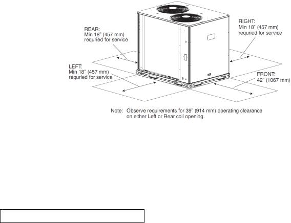
Select a location for the unit and its support system (pad, rails or other) that provides for the minimum clearances required for safety. This includes the clearance to combustible surfaces, unit performance and service access below, around and above unit as specified in unit drawings. See Service Clearance Dimensional Drawing.
NOTE: Local codes may require different clearances than specified in Service Clearance Dimensional Drawing. It is the responsibility of installers to be knowledgeable in local codes and to modify the recommended clearances to satisfy local codes.
NOTE: Consider also the effect of adjacent units on airflow performance and control box safety clearance.
Fig: - Service Clearance Dimensional Drawing
Do not install the outdoor unit in an area where fresh air supply to the outdoor coil may be restricted or when recirculation from the condenser fan discharge is possible. Do not locate the unit in a well or next to high walls. Evaluate the path and required line length for interconnecting refrigeration piping, including suction riser requirements (outdoor unit above indoor unit), liquid line lift (outdoor unit below indoor unit) and hot gas bypass line. Relocate sections to minimize the length of interconnecting tubing.
Although unit is weatherproof, avoid locations that permit water from higher level runoff and overhangs to fall onto the unit.
DO NOT BURY REFRIGERATION LINES.
Page 8

Step 2 — Complete Pre-Installation Checks
Check Unit Electrical Characteristics: Confirm before installation of unit that voltage, amperage and circuit protection requirements listed on unit data plate agree with power supply provided.
Un-crate Unit: Remove unit packaging except for the top skid assembly, which should be left in place until after the unit is rigged into its final location.
Inspect Shipment: File a claim with shipping company if the shipment is damaged or incomplete.
Consider System Requirements:
•Consult local building codes or the U.S.A. National Electrical Code (Ref: ANSI/NFPA 70, [American National Standards Institute/National Fire Protection Association], latest revision) for special installation requirements.
•Allow sufficient space for airflow clearance, wiring, refrigerant piping, and servicing unit. See Unit Dimensional Drawing for unit dimensions and weight distribution data.
•Locate the unit so that the outdoor coil (condenser) airflow is unrestricted on all sides and above.
•The unit may be mounted on a level pad directly on the base channels or mounted on raised pads at support points. See Unit Dimensional Drawing for unit operating weights and for weight distribution based on recommended support points.
NOTE: If vibration isolators are required for a particular installation, use the data in Unit Dimensional Drawing to make the proper selection.
Step 3 — Prepare Unit Mounting Support
Slab Mount — Provide a level concrete slab that extends a minimum of 150 mm (6 in.) beyond unit cabinet. Install a gravel apron in front of condenser coil air inlet to prevent grass and foliage from obstructing airflow.
Step 4 — Rig and Mount the Unit
 CAUTION
UNIT DAMAGE HAZARD
Failure to follow this caution may result in equipment damage.
All panels must be in place when rigging. Unit is not designed for handling by fork truck.
Rigging: These units are designed for overhead rigging. Refer to the rigging label for preferred rigging method. Spreader bars are not required if top crating is left on the unit. All panels must be in place when rigging. As further protection for coil faces, plywood sheets may be placed against the sides of the unit, behind cables. Run cables to a central suspension point so that the angle from the horizontal is not less than 45 degrees. Raise and set the unit down carefully. If it is necessary to roll the unit into position, mount the unit on longitudinal rails, using a minimum of 3 rollers. Apply force to the rails, not the unit. If the unit is to be skidded into position, place it on a large pad and drag it by the pad. Do not apply any force to the unit. Raise from above to lift the unit from the rails or pad when unit is in its final position. After the unit is in position, remove all shipping materials and top crating.
Step 5 — Complete Refrigerant Piping Connections
IMPORTANT: Do not bury refrigerant piping underground.
IMPORTANT: A refrigerant receiver is not provided with the unit. Do not install a receiver.
Provide Safety Relief
If local codes dictate an additional safety relief device, purchase locally and install locally. Installation will require the recovery of the factory shipping charge before the factory tubing can be cut and the supplemental relief device is installed. Model 38AUMD has two separate refrigeration systems. If required, each circuit will require a fieldsupplied/installed supplemental relief device.
Page 9
Check 38AUM Model with Evaporator Coil Connections
Confirm before installation of unit that the evaporator coil connections are consistent with this 38AUM model.
Determine Refrigerant Line Sizes
Select the recommended line sizes for 38AUMZ and 38AUMD unit from the appropriate tables. Determine the linear length of interconnecting piping required between the outdoor unit and indoor unit (evaporator). Consider and identify also the arrangement of the tubing path (quantity and type of elbows in both lines), liquid line solenoid size, filter drier and any other refrigeration specialties located in the liquid line. Refer to the indoor unit installation instructions for additional details on refrigeration specialties devices. Determine equivalent line length adjustments for path and components and add to linear line lengths. See Equivalent Lengths for Common Fittings (EN units), Equivalent Lengths for Common Fittings, for usual fitting types. Also identify adjustments for refrigeration specialties. Refer to Part 3 of the Carrier System Design Manual for additional data and information on equivalent lengths.
Equivalent Lengths for Common Fittings (EN units)
mm |
Nominal |
|
|
Elbows |
|
|
Tube OD |
90° |
90° |
90° |
45° |
45° |
|
Ref |
(in) |
Std |
Lrad |
Street |
Std |
Street |
9.5 |
3/8 |
0.40 |
0.24 |
0.67 |
0.18 |
0.30 |
12.7 |
1/2 |
0.43 |
0.27 |
0.70 |
0.21 |
0.34 |
15.9 |
5/8 |
0.49 |
0.30 |
0.76 |
0.24 |
0.40 |
19.1 |
3/4 |
0.55 |
0.37 |
0.88 |
0.27 |
0.46 |
22.2 |
7/8 |
0.61 |
0.43 |
0.98 |
0.27 |
0.49 |
28.6 |
1 - 1/8 |
0.79 |
0.52 |
1.25 |
0.40 |
0.64 |
34.9 |
1 - 3/8 |
1.01 |
0.70 |
1.71 |
0.52 |
0.91 |
41.3 |
1 - 5/8 |
1.22 |
0.79 |
1.92 |
0.64 |
1.04 |
54.0 |
2 - 1/8 |
1.52 |
1.01 |
2.50 |
0.79 |
1.37 |
mm |
Nominal |
|
Tees |
|
||
|
|
Straight-Thru |
||||
Tube OD |
Branch |
|
||||
Ref |
No |
Reduce |
Reduce |
|||
(in) |
Flow |
|||||
|
Reduct |
25% |
50% |
|||
|
|
|
||||
9.5 |
3/8 |
0.79 |
0.24 |
0.34 |
0.40 |
|
12.7 |
1/2 |
0.82 |
0.27 |
0.37 |
0.43 |
|
15.9 |
5/8 |
0.91 |
0.30 |
0.43 |
0.49 |
|
19.1 |
3/4 |
1.07 |
0.37 |
0.52 |
0.55 |
|
22.2 |
7/8 |
1.22 |
0.43 |
0.58 |
0.61 |
|
28.6 |
1 - 1/8 |
1.52 |
0.52 |
0.70 |
0.79 |
|
34.9 |
1 - 3/8 |
2.13 |
0.70 |
0.94 |
1.01 |
|
41.3 |
1 - 5/8 |
2.44 |
0.79 |
1.13 |
1.22 |
|
54.0 |
2 - 1/8 |
3.05 |
1.01 |
1.43 |
1.52 |
|
NOTE: Equivalent line lengths will vary based on tube diameter. Calculate equivalent line length for each pipe by adding equivalent length adjustments to linear lengths for each pipe. Enter the appropriate table to select the recommended line sizes.
Model: |
Line Sizes Table |
Quality of Line Sets |
38AUMZ |
5 |
1 |
38AUMD |
6 |
2 |
Liquid Lift
A liquid lift condition exists when the outdoor unit is located below the indoor (evaporator) unit and liquid flows vertically up in a portion of the liquid line. The vertical column of liquid reduces the available state point subcooling at the evaporator coil’s thermal expansion valve. This effect reduces the length of liquid lift (feet of elevation) that a liquid line size can accommodate. Longer linear tube lengths will also reduce the amount of liquid lift possible. Check Table Piping Recommendation for maximum liquid lift capabilities for line sizes. Reselect the liquid line tube size if necessary. If maximum available tube size cannot provide the required lift distance on this installation, relocate the outdoor unit to reduce the equivalent line length or the lift requirement.
Suction Riser
A suction riser condition exists when the outdoor unit is located above the indoor (evaporator) unit and suction vapor must flow vertically up to return to the compressor. Oil return is a concern when the suction tube size is too large to produce the minimum refrigerant velocity to ensure oil return at minimum load conditions. Check Table 38AUM Maximum Suction Pipe Size for maximum suction tube size for 38AUM units at minimum load conditions. Consider suction speed riser (reduced tube size for vertical segment only) or double suction riser arrangement if the proposed suction tube size does not provide necessary minimum flowrates for this riser.
38AUM Maximum Suction Pipe Size
Model: |
Unit Size |
Maximum Tube Size |
|
38AUMZ |
07 |
1 – 3/8 |
|
08 |
1 – 5/8 |
||
|
|||
38AUMD |
12 |
1 – 3/8 |
|
14 |
1 – 3/8 |
||
|
16 |
1 – 3/8 |
Page 10
Vertical Separation (outdoor unit above indoor unit)
Vertical elevation difference of 60 m (200 ft) is permitted when the outdoor unit (38AUMZ or 38AUMD) is located above the indoor unit.
Insulate Suction Lines
Apply closed-cell tubular insulation to all suction lines between evaporator coil connection and 38AUM unit’s suction service valve.
Hot Gas Bypass
Hot gas bypass, if used, should be introduced before the evaporator. (A bypass route that also bypasses the evaporator circuit may lead to oil trapping in the evaporator circuit during low load conditions and then to oil slugging as evaporator load increases.) Model 38AUM units do not include a hot gas stub connection; a tee must be fieldsupplied and installed in the compressor discharge line. Run a 1/2-in OD line between outdoor unit and evaporator coil inlet. Install an Auxiliary Side Connector at the evaporator between TXV and distributor (follow instructions for the side connector part). Insulate the hot gas line.
38AUMD: Generally only one hot gas bypass system will be applied on a two-circuit unit. Connect the hot gas bypass system to Circuit 1 (first-on/last-off, connected to the evaporator coil’s bottom circuit).
38AUMD Piping Connections
The 38AUMD’s two circuits are designated Circuit 1 and Circuit 2. Circuit 1 is controlled by the thermostat’s Y1 (or TC1) contact and will be the first circuit on and last circuit off. Circuit 2 is controlled by the thermostat’s Y2 (or TC2) contact and this circuit is always the “lag” circuit.
See Fig. 38AUMD Service Valve Locations for location of Circuit 1 and Circuit 2 service valves and field piping connections. Circuit 1 is on the right-hand side of the service valve compartment; Circuit 2 is on the left. When a single piece evaporator coil with two separate circuits is connected to a 38AUMD, the lower coil circuit should be connected to the 38AUMD’s Circuit 1 so that the evaporator’s lower coil segment is first-on/last-off (to avoid re-evaporation of condensate on dry lower coil segments).
Fig: - 38AUMD Service Valve Locations
Plan the Circuit 1 and Circuit 2 tubing segments carefully, mark each segment and check constantly as piping systems are assembled to avoid piping errors.
38AUMD unit cannot be field-piped as a single-circuit/tandem system.
Connecting 40RUM to 38AUMD: The 40RUM fan coil in sizes 12, 14 and 16 is a face-split coil design that also has its circuits designated as 1 and 2. See Fig: - Typical Evaporator Coil Connections (40RUM). Note that the lower coil segment changes as the arrangement of the 40RUM changes. In a vertical arrangement, the 40RUM’s lower coil segment is segment 2; this segment should be connected to the 38AUMD’s Circuit 1. In a horizontal arrangement, the 40RUM’s lower segment is now segment 1; this segment should be connected to the 38AUMD’s Circuit 1.
Note that refrigerant suction piping should be insulated.
Page 11

40RUM |
Cooling Stage |
40RUM Coil |
Connect to 38AUMD |
|
Arrangement |
Segment |
|||
|
|
|||
Vertical |
Y1 |
2 |
Circuit 1 |
|
Y2 |
1 |
Circuit 2 |
||
|
||||
Horizontal |
Y1 |
1 |
Circuit 1 |
|
Y2 |
2 |
Circuit 2 |
||
|
Fig: - Typical Evaporator Coil Connections (40RUM)
Install Filter Drier(s) and Moisture Indicator(s)
Every unit MUST have a filter drier in the liquid line. 38AUMD models require two filter driers (one in each liquid line). Locate the filter drier(s) at the indoor unit, close to the evaporator coil’s thermal expansion valve (TXV) inlets.
Installation of liquid line moisture indicating sightglass in each circuit is recommended. Locate the sightglass(es) between the outlet of the filter drier and the TXV inlet. In some applications, depending on space and convenience requirements, it may be desirable to install 2 filter driers and sight glasses in a single circuit application. One filter drier and sight glass may be installed at A locations
Select the filter drier for maximum unit capacity and minimum pressure drop. Complete the refrigerant piping from the indoor unit to the outdoor unit before opening the liquid and suction lines at the outdoor unit.
Fig: - Location of Sight Glass(es) and Filter Driers Typical 38AUMZ Systems
Page 12

Fig: - Location of Sight Glass(es) and Filter Driers Typical 38AUMD Systems
Install Liquid Line Solenoid Valve
It is recommended that a solenoid valve be placed in the main liquid line (see Figs: - Location of Sight Glass(es) and Filter Driers Typical 38AUMZ/D Systems) between the condensing unit and the evaporator coil. Locate the solenoid valve at the outlet end of the liquid line, near the evaporator coil connections, with flow direction arrow pointed at the evaporator coil. (A liquid line solenoid valve is required when the liquid line length exceeds 23m [75ft].) This valve prevents refrigerant migration (which causes oil dilution) to the compressor during the off cycle, at low outdoor ambient temperatures.
Solenoid drop control wiring: control the power to the liquid line solenoid through a Solenoid Valve Relay (SVR) in all units. Use part number HN61PC005 (field--supplied, installed). 38AUMZ unit requires one SVR; 38AUMD unit requires two relays. 38AUMD units also require a separate control power transformer for the liquid solenoid valve loads. Use transformer part number HT01BD602, according to unit power supply.
Mount the SVR (and transformer TRAN3 when used) in unit control box. Connect per wiring schematic label on unit or per Typical Wiring Schematic.
Capacity Control Liquid Line Solenoid Valve: Evaporator capacity staging control via direct thermostat control of a liquid solenoid valve on the evaporator’s second stage circuit is not possible with 38AU models. If this installation is a retrofit for a unit that included automatic pressure-operated unloading, check the existing thermostat and liquid solenoid valve wiring for possible direct thermostat control of a solenoid valve; re-wire per Fig: - Typical Piping Connection Assembly.
Selecting an Accumulator – Because all 38AUM models use scroll compressors, an accumulator is not required. If an accumulator is to be added, check the accumulator manufacturer’s literature carefully for indication of its suitability for use with R--410A; look for minimum working pressure of 1380 kPa (200 psig). Select the accumulator first on the basis of its cataloged minimum capacity (tons) to ensure oil return from the accumulator, then on tube size or holding capacity.
Make Piping Connections — Piping connections at the 38AUM unit are ball valves with stub tube extensions. Do not open the unit service valves until all interconnecting tube brazing has been completed. The stub tube connections include 1/4-in SAE service fittings with Schrader valve cores (see Fig: - Typical Piping Connection Assembly). Before making any brazed connections to the unit service valves, remove both Schrader valve caps and cores and save for re-installation. Connect a source for nitrogen to one of these service fittings during tube brazing to prevent the formation of copper oxides inside the tubes at brazed joints.
Page 13

Fig: - Typical Piping Connection Assembly
When connecting the field tubing to the 38AU service valves, wrap the valves in wet rags to prevent overheating Pressure-test all joints from outdoor unit connections over to the evaporator coil, using nitrogen as pressure and with soap-and-bubbles. When pressure-testing is completed, remove the nitrogen source at the outdoor unit service valves and re-install the two Schrader valve cores. Torque the cores to 23-34 N-cm (2-3 in-lbs).
Evacuation/Dehydration — Evacuate and dehydrate the connected refrigeration system(s) (excluding the 38AUM unit) to 500 microns using a two-stage vacuum pump attached to the service ports outside the 38AU service valves, following description in GTAC II, Module 4, System Dehydration.
 WARNING
UNIT OPERATION AND SAFETY HAZARD
Failure to follow this warning could cause personal injury, death and/or equipment damage.
Puron® (R-410A) refrigerant systems operate at higher pressure than standard R-22 systems. Do not use R-22 service equipment or components on Puron refrigerant equipment.
This unit is designed for use with Puron (R-410A) refrigerant. Do not use any other refrigerant in this system.
Puron (R-410A) refrigerant is provided in pink (rose) colored cylinders. These cylinders are available with and without dip tubes; cylinders with dip tubes will have a label indicating this feature. For a cylinder with a dip tube, place the cylinder in the upright position (access valve at the top) when removing liquid refrigerant for charging. For a cylinder without a dip tube, invert the cylinder (access valve on the bottom) when removing liquid refrigerant.
Because Puron (R-410A) refrigerant is a blend, it is strongly recommended that refrigerant always be removed from the cylinder as a liquid. Admit liquid refrigerant into the system in the discharge line. If adding refrigerant into the suction line, use a commercial metering/expansion device at the gauge manifold; remove liquid from the cylinder, pass it through the metering device at the gauge set and then pass it into the suction line as a vapor. Do not remove Puron (R-410A) refrigerant from the cylinder as a vapor.
Preliminary Charge — Before starting the unit, charge R-410A liquid refrigerant into the high side of each 38AUM circuit through the liquid service valve(s). The amount of refrigerant added must be compatible with the operating charge listed in Table Piping Recommendation for LINEAR line length LESS the factory charge quantity (if factory shipping charge has not been removed). See example below.
Note: See section “Adjust Refrigerant Charge” for details on refrigerant charge adjustment.
Allow high and low side pressures to equalize. If pressures do not equalize readily, charge R-410A vapor (using special service manifold with expansion device) into the suction line service port for the low side of system to assure charge in the evaporator. Refer to GTAC II, Module 5, Charging, Recover, Recycling, and Reclamation for liquid charging procedures.
Page 14
Loading...