


PIXMA iP5300
Service Manual
Revision 0
QY8-13BB-000
COPYRIGHTc2006 CANON INC. CANON PIXMAiP5300 082006 XX 0.00-0
Scope
This manual has been issued by Canon Inc., to provide the service technicians of this product with the information necessary for qualified persons to learn technical theory, installation, maintenance, and repair of products. The manual covers information applicable in all regions where the product is sold. For this reason, it may contain information that is not applicable to your region.
Revision
This manual could include technical inaccuracies or typographical errors due to improvements or changes made to the product. When changes are made to the contents of the manual, Canon will release technical information when necessary. When substantial changes are made to the contents of the manual, Canon will issue a revised edition.
The following do not apply if they do not conform to the laws and regulations of the region where the manual or product is used:
Trademarks
Product and brand names appearing in this manual are registered trademarks or trademarks of the respective holders.
Copyright
All rights reserved. No parts of this manual may be reproduced in any form or by any means or translated into another language without the written permission of Canon Inc., except in the case of internal business use.
Copyright © 2006 by Canon Inc. CANON INC.
Inkjet Device Quality Assurance Div. 2
451, Tsukagoshi 3-chome, Saiwai-ku, Kawasaki-shi, Kanagawa 212-8530, Japan

PIXMA iP5300
I. MANUAL OUTLINE
This manual consists of the following three parts to provide information necessary to service the PIXMA iP5300:
Part 1: Maintenance
Information on maintenance and troubleshooting of the PIXMA iP5300
Part 2: Technical Reference
New technology and technical information such as FAQ's (Frequently Asked Questions) of the PIXMA iP5300
Part 3: Appendix
Block diagrams and pin layouts of the PIXMA iP5300
Reference
This manual does not provide sufficient information for disassembly and reassembly procedures. Refer to the graphics in the separate Parts Catalog.
 <I. MANUAL OUTLINE>

PIXMA iP5300
II. TABLE OF CONTENTS
Part 1: MAINTENANCE
1. MAINTENANCE
1-1. Adjustment, Periodic Maintenance, Periodic Replacement Parts, and Replacement Consumables by Service Engineer
1-2. Customer Maintenance
1-3. Product Life
1-4. Special Tools
1-5. Serial Number Location
2.LIST OF ERROR DISPLAY / INDICATION 2-1. Operator Call Errors
2-2. Service Call Errors
2-3. Warnings
2-4. Troubleshooting by Symptom
3.REPAIR
3-1. Notes on Service Part Replacement
3-2. Special Notes on Repair Servicing
3-3. Adjustment / Settings
(1)Paper feed motor adjustment
(2)Grease application
(3)Ink absorber counter setting
(4)User mode
(5)Service mode
Service test print, EEPROM initialization, Ink absorber counter resetting Destination setting
LF / Eject correction Left margin correction
3-4. Verification Items
(1)Service test print
(2)EEPROM information print
4.MACHINE TRANSPORTATION
Part 2: TECHNICAL REFERENCE
1.NEW TECHNOLOGIES
2.CLEANING MODE AND AMOUNT OF INK PURGED 2-1. Cleaning
2-2. Moisturizing Timer Sequence
3.PRINT MODE
4.FAQ (Problems Specific to the iP5300 and Corrective Actions)
Part 3: APPENDIX
1.BLOCK DIAGRAM
2.CONNECTOR LOCATION AND PIN LAYOUT 2-1. Logic Board
2-2. Carriage Board (Print Head Connector)
3.PIXMA iP5300 SPECIFICATIONS
 <II. TABLE OF CONTENTS>

Part 1: MAINTENANCE |
TABLE OF CONTENTS |
|
|
1. MAINTENANCE
1-1. Adjustment, Periodic Maintenance, Periodic Replacement Parts, and Replacement Consumables by Service Engineer
(1) Adjustment
|
|
Adjustment |
|
Timing |
|
Purpose |
|
Tool |
|
Approx. time |
|
|
Destination settings |
|
- At logic board |
|
To set destination. |
|
None. |
|
1 min. |
|
|
(EEPROM settings) |
|
replacement |
|
|
|
Perform in the |
|
|
|
|
|
|
|
|
|
|
service mode. |
|
|
|
|
Ink absorber counter |
|
- At logic board |
|
To reset the ink absorber counter. |
|
None. |
|
1 min. |
|
|
resetting |
|
replacement |
|
|
|
Perform in the |
|
|
|
|
(EEPROM settings) |
|
- At ink absorber |
|
|
|
service mode. |
|
|
|
|
|
|
replacement |
|
|
|
|
|
|
|
|
Paper feed motor position |
|
- At paper feed |
|
To adjust the belt tension.(Position the |
|
None. |
|
5 min. |
|
|
adjustment |
|
motor replacement |
|
paper feed motor so that the belt is |
|
|
|
|
|
|
|
|
|
|
stretched tight.) |
|
|
|
|
|
|
CD / DVD detection sensor |
|
- At logic board |
|
To correct the light volume for the CD / |
|
None. |
|
2 min. |
|
|
light volume correction |
|
replacement |
|
DVD detection sensor. |
|
Perform in the |
|
|
|
|
|
|
- At carriage unit |
|
|
|
service mode. |
|
|
|
|
|
|
replacement |
|
|
|
|
|
|
|
|
Grease application |
|
- At carriage unit |
|
To maintain sliding properties of the |
|
FLOIL KG- |
|
1 min. |
|
|
|
|
replacement |
|
following items: |
|
107A |
|
|
|
|
|
|
- At lift cam |
|
- Carriage shaft |
|
|
|
|
|
|
|
|
replacement |
|
- Lift cam bushing |
|
|
|
|
|
|
|
|
- To gears |
|
- Printer sliding portions (gears) |
|
|
|
|
|
|
Ink system function check |
|
- At logic board |
|
To maintain detection functionality for |
|
None. |
|
1 min. |
|
|
|
|
replacement |
|
presence of the ink tanks and each ink tank |
|
Perform in the |
|
|
|
|
|
|
- At platen unit |
|
position. |
|
service mode. |
|
|
|
|
|
|
replacement |
|
|
|
|
|
|
|
|
|
|
- At carriage unit |
|
|
|
|
|
|
|
|
|
|
replacement |
|
|
|
|
|
|
|
|
LF correction |
|
- At logic board |
|
To correct line feeding. |
|
None. |
|
5 min.* |
|
|
|
|
replacement |
|
|
|
Perform in the |
|
|
|
|
|
|
- At feed roller ass'y |
|
|
|
service mode. |
|
|
|
|
|
|
replacement |
|
|
|
|
|
|
|
|
Eject correction |
|
- At logic board |
|
To maintain the paper eject accuracy |
|
None. |
|
|
New |
|
replacement |
|
|
|
|
|
|
||
|
- At platen unit |
|
|
|
|
|
|
|||
|
|
|
|
|
|
|
|
|
|
|
|
|
|
|
replacement |
|
|
|
|
|
|
* LF and eject corrections are performed at the same time.
Caution: DO NOT loosen the red screws at both ends of the carriage shaft, securing the print head position, as they are not readjustable.
The red screws securing the paper feed motor may be loosened only at replacement of the paper feed motor unit.
(2) Periodic maintenance
No periodic maintenance is necessary.
(3) Periodic replacement parts
There are no parts in this printer that require periodic replacement by a service engineer.
(4) Replacement consumables
There are no consumables that require replacement by a service engineer.
1-1

1-2. Customer Maintenance
Adjustment |
|
Timing |
|
Purpose |
|
Tool |
|
Approx. time |
Automatic print |
|
- At print head replacement |
|
To secure the dot |
|
- 2 sheets of Matte Photo Paper |
|
13 min. |
head alignment |
|
- When print quality is not satisfying, |
|
placement |
|
(MP-101) |
|
|
|
|
and not improved by print head |
|
accuracy. |
|
- Printer buttons |
|
|
|
|
cleaning. |
|
|
|
- Computer (automatic alignment |
|
|
|
|
|
|
|
|
via printer driver) |
|
|
Manual print head |
|
- At print head replacement |
|
To secure the dot |
|
- 5 sheets of plain paper |
|
15 min. |
alignment |
|
- When print quality is not satisfying, |
|
placement |
|
- Printer buttons |
|
|
|
|
and not improved by print head |
|
accuracy. |
|
- Computer (printer driver with |
|
|
|
|
cleaning. |
|
|
|
the manual print head |
|
|
|
|
|
|
|
|
alignment selected) |
|
|
Print head cleaning |
|
When print quality is not satisfying. |
|
To improve nozzle |
|
- Printer buttons |
|
1 min. |
|
|
|
|
conditions. |
|
- Computer (printer driver) |
|
|
Print head deep |
|
When print quality is not satisfying, and |
|
To improve nozzle |
|
- Computer (printer driver) |
|
2 min. |
cleaning |
|
not improved by print head cleaning. |
|
conditions. |
|
|
|
|
Ink tank |
|
When an ink tank becomes empty. ("No |
|
― |
|
― |
|
2 min. |
replacement |
|
ink error" displayed on the monitor, or |
|
|
|
|
|
|
|
|
short flashing of an ink tank LED) |
|
|
|
|
|
|
Paper feed roller |
|
When paper does not feed properly. |
|
To clean the paper |
|
- Printer buttons |
|
2 min. |
cleaning |
|
|
|
feed rollers. |
|
|
|
|
CD / DVD print |
|
At CD / DVD printing, when necessary. |
|
To correct CD / |
|
- Computer (application software) |
|
5 min. |
position adjustment |
|
|
|
DVD print |
|
|
|
|
|
|
|
|
position. |
|
|
|
|
Bottom plate |
|
When the back side of the paper is |
|
To clean the |
|
- Plain paper |
|
1 min. |
cleaning |
|
smeared. |
|
platen ribs. |
|
- Computer (printer driver) |
|
|
ASF subroller |
|
When the paper fed from the ASF is |
|
To clean the ASF |
|
- Plain paperPrinter buttons |
|
1 min. |
cleaning |
|
smeared due to ink mist attached to the |
|
sub-rollers. |
|
See Part 2, 4. FAQ, How to |
|
|
|
|
ASF sub-rollers. |
|
|
|
make and set the ASF sub- |
|
|
|
|
|
|
|
|
roller cleaning sheet, for |
|
|
|
|
|
|
|
|
details. |
|
|
1-2
1-3. Product Life
(1) Printer
Specified print volume (I) or the years of use (II), whichever comes first.
(I) Print volume: 21,000 pages
Black |
1500 character pattern |
8,400 pages |
|
|
|
Color |
7.5% duty per color pattern |
6,300 pages |
|
A4, photo, borderless printing |
400 pages |
|
4 x 6, photo, borderless printing |
4,400 pages |
|
Postcard, photo, borderless printing |
1,500 pages |
|
|
|
(II) Years of use: 5 years of use
(2)Print head
Print volume: 28,560 pages
(3) Ink tank (target value)
Average yield |
|
PGI-5BK |
|
CLI-8BK |
|
CLI-8C |
|
CLI-8M |
|
CLI-8Y |
( ): Estimated supplemental yield |
|
|
|
|
|
|||||
|
|
|
|
|
|
|
|
|
|
|
Color document (ISO/IEC FCD24712)*1 |
|
530 pages |
|
(5,395 pages) |
|
890 pages |
|
695 pages |
|
710 pages |
Photo (4" x 6")*2 |
|
(4,340 pages) |
|
(1,600 pages) |
|
436 pages |
|
290 pages |
|
331 pages |
*1: Declared yield value in accordance with ISO/IEC FCD24711. Values obtained by continuous printing.
*2: When printing Canon standard patterns on 4" x 6" Photo Paper Plus Glossy continuously with the default settings of Photo Paper Plus Glossy using Windows XP printer driver in borderless printing mode and Windows XP Photo Printing Wizard. Declared yield value determined based on Canon standard method referring to ISO/IEC FCD24712.
Note: Ink yield may vary depending on texts/photos printed, applications software used, print mode and type of paper used.
1-4. Special Tools
Name |
|
Tool No. |
|
Price |
|
Application |
|
Remarks |
|
|
(JPY) |
|
|
||||
|
|
|
|
|
|
|
|
|
FLOIL KG-107A |
|
QY9-0057-000 |
210 |
|
To the carriage shaft sliding portions, and lift cam |
|
In common with the |
|
|
|
bushing |
|
S520. |
||||
|
|
|
|
|
|
|
||
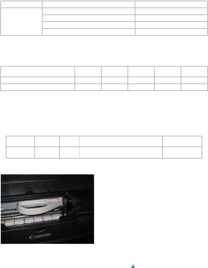
1-5. Serial Number Location
On the carriage flexible cable holder (visible on the right of the carriage after the printer is turned on, the top cover is opened, and the carriage moves to the center).
 <Part 1: 1. MAINTENANCE>
1-3

Part 1: MAINTENANCE |
TABLE OF CONTENTS |
|
|
2. LIST OF ERROR DISPLAY / INDICATION
Errors are indicated by the LED, and warnings are displayed on the monitor of the computer connected to the printer.
2-1. Operator Call Errors (by Alarm LED Blinking in Orange)
LED |
|
Error |
blinking |
|
[Error code] |
2 times |
|
No paper in the ASF. [1000] |
|
|
No CD / DVD tray. [1001] |
Solution |
|
Remarks |
|
|
|
Set the paper in the ASF, and press the
Resume/Cancel button.
Set the CD / DVD tray, and press the
Resume/Cancel button.
|
No paper in the cassette. |
Set the paper in the cassette, and press the |
|
|
[1003] |
Resume/Cancel button. |
|
|
No CD or DVD. [1002] |
Set a CD or DVD in the CD / DVD tray (which is |
|
|
|
ejected at error occurrence), and inset the CD / |
|
|
|
DVD tray in the proper position. Then, press the |
|
|
|
Resume/Cancel button. |
|
3 times |
Paper jam. [1300] |
Remove the jammed paper, and press the |
Error during paper feeding from the ASF |
|
|
Resume/Cancel button. |
|
|
Paper jam in the rear guide. |
|
Error in the duplexing transport unit |
|
[1303] |
|
|
Paper jam in the under guide. [1304]
Front door close error. |
Open the paper output tray. |
[1250] |
|
Error during paper feeding from the cassette
The error is indicated if the paper output tray is closed at start of a print job, or while a print job is being performed.
4 times |
Ink may have run out. |
|
[1600] |
|
Ink tank not installed. |
|
[1660] |
5 times |
- Print head not installed, or |
|
not properly installed. |
|
[1401] |
|
- Print head temperature |
|
sensor error. [1403] |
|
- Faulty EEPROM data of |
|
the print head. [1405] |
|
- Print head hardware error. |
|
[1682] |
6 times |
Inner cover open during |
|
printing on paper (print |
|
continuable). [1851] |
|
Inner cover open during |
|
printing on paper (print |
|
NOT continuable). [1856] |
|
Inner cover closed before |
|
start of CD / DVD printing |
|
(print continuable). [1850] |
|
Inner cover closed during |
|
CD / DVD printing (print |
|
NOT continuable). [1855] |
Replace the applicable ink tank, or press the Resume/Cancel button to clear the error without ink tank replacement.
Install the applicable ink tank(s) properly, and confirm that the LED's of all the ink tanks light red.
Install the print head properly.
Close the inner cover, and press the Resume/Cancel button.
Close the inner cover, and press the Resume/Cancel button to clear the error. The paper being printed at error occurrence will be ejected without printing the remaining data for the ejected paper, then printing will resume from the next page.
Open the inner cover which functions as the CD / DVD tray feeder, set the CD / DVD tray in the feeder, and press the Resume/Cancel button.
Open the inner cover, and press the Resume/Cancel button to clear the error. The CD or DVD being printed at error occurrence will be ejected without
1-4
When the error is cleared by pressing the Resume/Cancel button, ink may run out during printing.

printing the remaining data for the ejected CD or DVD, then the next print job will be performed.
7 times |
Multiple ink tanks of the |
Replace the wrong ink tank(s) with the correct one |
|
|
same color installed. [1681] |
(s). |
|
|
Ink tank in a wrong |
Install the ink tank(s) in the correct position. |
|
|
position. [1680] |
|
|
8 times |
Warning: The ink absorber |
Press the Resume/Cancel button. |
The service call error, indicating the ink |
|
becomes almost full. [1700] |
|
absorber is full, is likely to occur soon. |
9 times |
The connected digital |
Remove the cable between the camera and the |
|
|
camera or digital video |
printer. |
|
|
camera does not support |
|
|
|
Camera Direct |
|
|
|
Printing. [2001] |
|
|
10 times Automatic duplex printing |
Press the Resume/Cancel button to eject the paper |
cannot be performed. [1310] |
being used at error occurrence. Printing will resume |
|
from on the front side of the next page. |
11 times Failed in automatic print head alignment. [2500]
Press the Resume/Cancel button.
-If paper is being fed at error occurrence, the error is indicated after the paper is ejected.
-If the error occurs, the print head alignment values are not changed.
-After exit from the error by the Resume/Cancel button, the automatic print head alignment will not be re-done.
Data which was to be printed on the back side of paper at error occurrence is skipped (not printed).
The error will occur (a) when the print head alignment pattern is not printed due to no ink or non-ejection of ink, (b) when the sensor's AD value is incorrect, or (c) when the paper is shorter than the specified length.
13 times |
The remaining ink amount |
Replace the applicable ink tank with a new one, and |
|
unknown. [1683] |
close the scanning unit (printer cover). |
|
|
Printing with a once-empty ink tank can damage the |
|
|
printer. |
|
|
To continue printing without replacing the ink tank |
|
|
(s), press the Resume/Cancel button for 5 sec. or |
|
|
longer to disable the function to detect the |
|
|
remaining ink amount. After the operation, it is |
|
|
recorded in the printer EEPROM that the function |
|
|
to detect the remaining ink amount was disabled. |
14 times |
Ink tank not recognized. |
A non-supported ink tank is installed (the ink tank |
|
[1684] |
LED is turned off). Install the supported ink tanks. |
15 times |
Ink tank not recognized. |
A hardware error occurred in an ink tank (the ink |
|
[1410 to 1414] |
tank LED is turned off). Replace the ink tank(s). |
|
|
Each error code corresponds to each ink tank, from |
|
|
left (the opposite side of the home position) to right, |
|
|
respectively. Error code 1410 is for the leftmost ink |
|
|
tank (PGI-5BK). |
The error is indicated when raw ink is detected but the dot count number exceeds the threshold of complete exhaustion of ink.
Ink tank positioning (from left to right): BK, PigBK, Y, M, C
16 times No ink. [1688] |
Replace the empty ink tank(s), and close the |
|
scanning unit (printer cover). |
|
Printing with an empty ink tank can damage the |
|
printer. |
|
To continue printing without replacing the ink tank |
|
(s), press the Resume/Cancel button for 5 sec. or |
|
longer to disable the function to detect the |
|
remaining ink amount. After the operation, it is |
|
recorded in the printer that the function to detect the |
|
remaining ink amount was disabled. |
The error is indicated when "no raw ink" is detected and when the dot count number exceeds the threshold of complete exhaustion of ink.
1-5

2-2. Service Call Errors (by Cyclic Blinking in Orange (Alarm LED) and Green (Power LED), or Alarm LED Lit in Orange)
Cycles of blinking in |
|
|
|
Solution |
orange (Alarm LED) |
|
Error |
|
|
and green (Power |
|
|
(Replacement of listed parts, which are likely to be faulty) |
|
|
|
|
||
LED) |
|
|
|
|
2 times |
|
Carriage error [5100] |
|
- Carriage unit (QM2-3999) |
|
|
|
|
- Timing slit strip film (QC1-6526) |
|
|
|
|
- Logic board ass'y (QM3-0833)*1 |
|
|
|
|
- Carriage motor (QK1-1500) |
3 times |
|
Line feed error [6000] |
|
- Timing sensor unit (QM3-1271) |
|
|
|
|
- Timing slit disk film (QC2-0475) |
|
|
|
|
- Feed roller ass'y (QL2-1490) |
|
|
|
|
- Logic board ass'y (QM3-0833)*1 |
|
|
|
|
- Paper feed motor (QK1-1502) |
4 times |
|
Purge cam sensor error [5C00] |
|
- Purge unit (QM3-0007) |
|
|
|
|
- Logic board ass'y (QM3-0833)*1 |
5 times |
|
ASF (cam) sensor error [5700] |
|
- Sheet feed unit (QM2-3902) |
6 times |
|
Internal temperature error [5400] |
|
- Logic board ass'y (QM3-0833)*1 |
|
|
|
|
- Carriage unit (QM2-3999) |
7 times |
|
Ink absorber full [5B00] |
|
- Ink absorber kit (QY5-0179) |
8 times |
|
Print head temperature rise error [5200] |
|
- Print head (QY6-0067) |
|
|
|
|
- Logic board ass'y (QM3-0833)*1 |
9 times |
|
EEPROM / NVRAM error [6800] |
|
- Logic board ass'y (QM3-0833)*1 |
10 times |
|
VH monitor error [B200] |
|
- Logic board ass'y (QM3-0833)*1 |
|
|
|
|
- Print head (QY6-0067) |
11 times |
|
Carriage lift mechanism error [5110] |
|
- PR lift shaft ass'y (QL2-1450) |
|
|
|
|
- Sheet feed unit (QM2-3902) |
|
|
|
|
- Logic board ass'y (QM3-0833)*1 |
|
|
|
|
- Carriage lift sensor unit (QM3-1273) |
12 times |
|
AP position error [6A00] |
|
- Sheet feed unit (QM2-3902) |
|
|
|
|
- Logic board ass'y (QM3-0833)*1 |
|
|
|
|
- Purge unit (QM3-0007) |
13 times |
|
Paper feed position error [6B00] |
|
- Sheet feed unit (QM2-3902) |
|
|
|
|
- Logic board ass'y (QM3-0833)*1 |
14 times |
|
Paper feed cam sensor error [6B10] |
|
- Sheet feed unit (QM2-3902) |
|
|
|
|
- Logic board ass'y (QM3-0833)*1 |
15 times |
|
USB Host VBUS overcurrent [9000] |
|
- Logic board ass'y (QM3-0833)*1 |
16 times |
|
Pump roller sensor error [5C20] |
|
- Logic board ass'y (QM3-0833)*1 |
|
|
|
|
- Purge unit (QM3-0007) |
17 times |
|
Paper eject encoder error [6010] |
|
- Timing sensor unit (QM3-1271) |
|
|
|
|
- Timing slit disk eject film (QC2-0476) |
|
|
|
|
- Logic board ass'y (QM3-0833)*1 |
|
|
|
|
- Paper feed motor (QK1-1502) |
|
|
|
|
- Platen unit (QM3-0001) |
19 times |
|
Ink tank position sensor error [6502] |
|
- Platen unit (QM3-0001) |
|
|
|
|
- Logic board ass'y (QM3-0833)*1 |
20 times |
|
Other hardware error [6500] |
|
- Logic board ass'y (QM3-0833)*1 |
Power LED turned off, |
|
ROM / RAM error |
|
- Logic board ass'y (QM3-0833)*1 |
and Alarm LED lit |
|
|
|
|
1-6

*1: Before replacement of the logic board ass'y, check the ink absorber counter value (by service test print or EEPROM information print). If the counter value is 7% or more, also replace the Ink absorber kit (QY5-0179) when replacing the logic board ass'y. [See 3-3. Adjustment / Settings, (5) Service mode, for details.]
2-3. Warnings
Displayed warning |
|
Remarks |
Low ink |
|
Status indication only. |
Print head temperature rise |
|
If the print head temperature is high when the top cover is opened, the warning is |
|
|
displayed*1. |
|
|
When the print head temperature falls, the warning is released. |
Protection of excess rise of the print head |
|
If the print head temperature exceeds the specified limit, a Wait is inserted during |
temperature |
|
printing, |
*1: If the warning is displayed, the carriage does not move to the ink tank replacement position when the top cover is opened.
2-4. Troubleshooting by Symptom
|
|
Symptom |
|
Solution |
Faulty operation |
The power does not turn on. |
|
The power turns off immediately after |
|
power-on. |
|
A strange noise occurs. |
-Replace the
-AC adapter, or
-logic board ass'y*1.
-Remove foreign material.
-Attach a removed part if any.
|
Printing stops mid-way. |
- Replace the logic board ass'y*1. |
Paper feed problems |
Multiple sheets feed. |
- Replace the |
|
|
- sheet feed unit, or |
|
|
- cassette. |
|
Paper does not feed. |
- Remove foreign material. |
|
|
- Replace the |
|
|
- sheet feed unit, or |
|
|
- cassette. |
|
Paper feeds at an angle. |
- Remove foreign material. |
|
|
- Adjust the paper guide. |
|
|
- Replace the |
|
|
- sheet feed unit, or |
|
|
- cassette. |
Unsatisfactory print quality |
No printing, or no color ejected. |
- Replace the |
|
|
- ink tank, |
|
|
- print head*2, or |
|
|
- logic board ass'y*1. |
|
|
- Remove foreign material from the purge unit caps, if any. |
|
|
- Replace the purge unit. |
|
Printing is faint, or white lines appear on |
- Remove and re-install the print head. |
|
printouts even after print head cleaning. |
- Replace the |
|
Line(s) not included in the print data |
- ink tank, or |
|
appears on printouts. |
- print head*2. |
|
|
|
|
|
- Perform print head alignment*3. |
|
|
- Replace the |
|
|
- purge unit, or |
|
|
- logic board ass'y*1. |
|
Paper gets smeared. |
- Feed several sheets of paper. |
1-7
|
- Perform bottom plate cleaning. |
|
- Clean the paper path with cotton swab or cloth. |
|
- Clean the ASF sub-rollers. |
A part of a line is missing on printouts. |
- Replace the |
|
- ink tank, or |
|
- print head*2. |
Color hue is incorrect. |
- Replace the |
|
- ink tank, or |
|
- print head*2. |
|
- Perform print head alignment*3. |
Printing is incorrect. |
Replace the logic board ass'y*1. |
No ejection of black ink. |
- Replace the |
|
- ink tank, or |
|
- print head*2. |
|
- Remove foreign material from the purge unit caps, if any. |
|
- Replace the purge unit. |
Graphic or text is enlarged on printouts. |
When enlarged in the carriage movement direction: |
|
- Clean grease or oil off the timing slit strip film |
|
- Replace the |
|
- timing slit strip film, |
|
- carriage unit, or |
|
- logic board ass'y*1. |
|
When enlarged in the paper feed direction: |
|
- Clean grease or oil off the timing slit disk film and timing slit |
|
disk eject film. |
|
- Replace the |
|
- timing slit disk film, |
|
- timing slit disk eject film, |
|
- timing sensor unit, or |
|
- logic board ass'y*1. |
*1: Before replacement of the logic board ass'y, check the ink absorber counter value (by service test print or EEPROM information print). If the counter value is 7% or more, also replace the ink absorber kit (QY5-0179) when replacing the logic board ass'y. [See 3-3. Adjustment / Settings, (5) Service mode, for details.]
*2: Replace the print head only after the print head deep cleaning is performed 2 times, and when the problem persists.
*3: For automatic print head alignment, use Matte Photo Paper (MP-101). For manual print head alignment, plain paper can be used.
 <Part 1: 2. LIST OF ERROR DISPLAY / INDICATION>
1-8

Part 1: MAINTENANCE |
TABLE OF CONTENTS |
|
|
3. REPAIR
3-1. Notes on Service Part Replacement (and Disassembling / Reassembling)
Service part |
|
Notes on replacement*1 |
|
|
Adjustment / settings |
Logic board ass'y |
|
- Before removal of the logic |
|
After replacement: |
|
QM3-0833 |
|
board ass'y, remove the power |
1. |
Initialize the EEPROM. |
|
|
|
cord, and allow for approx. 1 |
2. |
Reset the ink absorber |
|
|
|
minute (for discharge of |
|
|
counter. |
|
|
capacitor's accumulated |
3. |
Set the destination in the |
|
|
|
charges), to prevent damages to |
|
|
EEPROM. |
|
|
the logic board ass'y. |
4. |
Correct the CD / DVD and |
|
|
|
- Before replacement, check the |
|
|
automatic print head |
|
|
ink absorber counter value (by |
|
|
alignment sensors. |
|
|
service test print or EEPROM |
5. |
Check the ink system |
|
|
|
information print). If the value |
|
|
function. |
|
|
is 7% or more, also replace the |
|
|
[See 3-3. Adjustment / |
|
|
ink absorber kit when replacing |
|
|
Settings, (5) Service mode, |
|
|
the logic board ass'y. |
|
|
for details of 1 to 5.] |
|
|
[See 3-3. Adjustment / Settings, |
6. |
Perform LF / Eject |
|
|
|
(5) Service mode, for details.] |
|
|
correction. |
|
|
|
7. |
Perform the print head |
|
|
|
|
|
|
alignment in the user |
|
|
|
|
|
mode*1. |
Ink absorber kit |
|
|
|
After replacement: |
|
QY5-0179 |
|
|
1. |
Reset the ink absorber |
|
|
|
|
|
|
counter. |
|
|
|
|
|
[See 3-3. Adjustment / |
|
|
|
|
|
Settings, (5) Service mode, |
|
|
|
|
|
for details.] |
Carriage unit |
|
|
|
At replacement: |
|
QM2-3999 |
|
|
1. |
Apply grease to the sliding |
|
|
|
|
|
|
portions. |
|
|
|
|
|
[See 3-3. Adjustment / |
|
|
|
|
|
Settings, (2) Grease |
|
|
|
|
|
application.] |
|
|
|
|
After replacement: |
|
|
|
|
1. |
Correct the CD / DVD and |
|
|
|
|
|
|
automatic print head |
|
|
|
|
|
alignment sensors. |
|
|
|
|
|
[See 3-3. Adjustment / |
|
|
|
|
|
Settings, (5) Service mode, |
|
|
|
|
|
for details.] |
|
|
|
2. |
Check the ink system |
|
|
|
|
|
|
function. |
|
|
|
|
|
[See 3-3. Adjustment / |
|
|
|
|
|
Settings, (5) Service mode, |
|
|
|
|
|
for details.] |
|
|
|
3. |
Perform the print head |
|
|
|
|
|
|
alignment in the user |
|
|
|
|
|
mode*1. |
Paper feed motor |
|
- The red screws securing the |
|
At replacement: |
|
QK1-1502 |
|
paper feed motor are allowed to |
1. |
Adjust the paper feed motor. |
|
|
|
be loosened. (DO NOT loosen |
|
|
[See 3-3. Adjustment / |
|
|
any other red screws.) |
|
|
Settings, (1) Paper feed |
|
|
|
|
|
motor adjustment.] |
Platen unit |
|
|
|
After replacement: |
|
QM3-0001 |
|
|
1. |
Check the ink system |
|
|
|
|
|
|
function. |
|
|
|
|
|
[See 3-3. Adjustment / |
|
|
|
|
1-9Settings, (5) Service mode, |
|
Operation check
-EEPROM information print
-Service test print
-Printing via USB connection
-Direct printing from a digital camera
-Service test print
-EEPROM information print
-Service test print (Confirm CD / DVD and automatic print head alignment sensor correction, and ink system function.)
- Service test print

PR lift shaft ass'y
QL2-1450
Input carriage lift gear QC2-1873
Timing slit strip film QC1-6526
Timing slit disk film QC2-0475
Timing slit disk eject film QC2-0476
for details.] |
|
At replacement: |
- Service test print |
1.Apply grease to the sliding portions.
[See 3.3. Adjustment / Settings, (2) Grease application.]
- Wipe off any grease from the |
After replacement: |
- Service test print |
film with ethanol. |
1. Perform the print head |
|
- Confirm no grease is on the |
alignment in the user |
|
film. (Wipe off any grease |
mode*1. |
|
thoroughly with ethanol.) |
|
|
- Do not bend the film. |
|
|
Print head |
After replacement: |
- Service test print |
QY6-0067 |
1. Perform the print head |
|
|
alignment in the user |
|
|
mode*1. |
|
*1: For automatic print head alignment, use Matte Photo Paper (MP-101). For manual print head alignment, plain paper can be used.
General notes:
-Make sure that the flexible cables and wires in the harness are in the proper position and connected correctly. [See 3-2. Special Notes on Repair Servicing, (5) Flexible cable and harness wiring, connection, for details.]
-Do not drop the ferrite core, which may cause damage.
-Protect electrical parts from damage due to static electricity.
-Before removing a unit, after removing the power cord, allow the printer to sit for approx. 1 minute (for capacitor discharging to protect the logic board ass'y from damages).
-Do not touch the timing slit strip film, timing slit disk film, and timing slit disk eject film. No grease or abrasion is allowed.
-Protect the units from soiled with ink.
-Protect the housing from scratches.
-Exercise caution with the red screws, as follows:
i.The red screws of the paper feed motor may be loosened only at replacement of the paper feed motor unit (DO NOT loosen them in other cases).
ii.DO NOT loosen the red screws on both sides of the main chassis, securing the carriage shaft positioning (they are
not adjustable in servicing)
 <Part 1: 3-1. Notes on Service Part Replacement>
1-10
Part 1: MAINTENANCE |
TABLE OF CONTENTS |
|
|
3-2. Special Notes on Repair Servicing
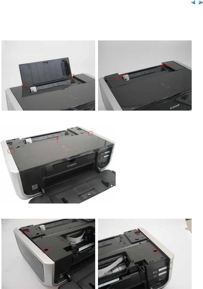
(1)External cover removal
(i)Remove the paper support unit (left photo) and the main case cover (right photo).
(ii) Remove the access cover.
(iii) Remove the side covers L and R.
1-11
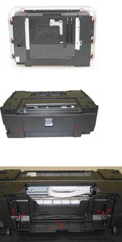
(iv) Remove the main case by inserting tool like precision screw driver into the 2 holes (at red marked) at the rear side.
(v)1) Open the front door and the inner cover.(1)
2)Push the (2) arrow-indicated portions to release the locks, then lift the main case upward to remove it.
3)Remove the interface cover.
1-12

(2) Door damper removal
Door damper location:
Removal:
While pulling the claw upward to release the lock ((1) in the photo below), slide the damper to the left ((2) in the photo below) to remove it.
1-13

(3) Front door removal
Open the paper output tray, and extend the output tray extension.
By bending the front door on both sides as shown in the photo below, the front door can be removed easily.
(4) Printer unit removal
The printer unit is fastened to the bottom case with 5 screws.
To remove the screw beneath the carriage unit in the home position, unlock the carriage unit first as follows:
(i) Unlock the carriage unit.
Rotate the gear (indicated by the red square) toward the rear side of the printer 2 or 3 times. The carriage will be unlocked.
1-14

(ii) Slide the carriage to the opposite of the home position, and remove the screw.
(5) Flexible cable and harness wiring, connection
Be cautious of wiring of the flexible cables and harness. Improper wiring or connection may cause breakage of a line, leading to ignition or emission of smoke.
(i) Logic board ass'y wiring
1-15

(ii) Paper feed motor side wiring
 <Part1: 3-2. Special Notes on Repair Servicing>
1-16

Part 1: MAINTENANCE |
TABLE OF CONTENTS |
|
|
3-3. Adjustment / Settings
(1) Paper feed motor adjustment
Perform the following adjustments when the paper feed motor unit is replaced:
1)When attaching the motor, fasten the screws so that the belt is properly stretched (in the direction indicated by the blue arrow in the figure below).
2)After replacement, be sure to perform the service test print, and confirm that no strange noise or faulty print operation (due to dislocation of the belt or gear, or out-of-phase motor, etc.) occurs.
Caution:
The red screws securing the paper feed motor may be loosened only at replacement of the paper feed motor unit. DO NOT loosen them in other cases.
(2) Grease application
<Printer Unit>
No |
Part name |
Where to apply grease / oil |
1Chassis ass'y
2Adjust plate L
3Chassis ass'y
4Adjust plate R
5Chassis ass'y
6Chassis ass'y
7Idler pulley
8Carriage shaft
9Carriage shaft spring L
10 Carriage shaft
Entire surface the carriage slider contacts
Carriage shaft cam L sliding portion
Carriage shaft sliding portion on the left side of the chassis (1 location)
Carriage shaft cam R sliding portion
Carriage shaft sliding portion on the right side of the chassis (1 location)
PR lift shaft cam contact portion (3 locations)
The shaft surface which contacts the idler pulley hole
Entire surface of the carriage shaft where the carriage unit slides
Carriage shaft sliding portion (to the end of the spring)
Carriage shaft surface where the carriage unit slides (and where the machineapplication of the grease is not feasible)
Drawing |
Grease / oil |
Grease / oil |
Number of |
|
amount |
drops* x |
|||
No. |
||||
|
(mg) |
locations |
||
|
|
|||
(1) |
Floil KG107A |
27 to 54 |
3 x 1 |
|
(2) |
Floil KG107A |
18 to 36 |
2 x 1 |
|
(3) |
Floil KG107A |
9 to 18 |
1 x 1 |
|
(4) |
Floil KG107A |
18 to 36 |
2 x 1 |
|
(5) |
Floil KG107A |
9 to 18 |
1 x 1 |
|
(6) |
Floil KG107A |
18 to 27 |
1.5 x 3 |
|
(7) |
Floil KG107A |
9 to 18 |
1 x 1 |
|
(8) |
Floil KG107A |
200 to 400 |
|
|
(9) |
Floil KG107A |
9 to 18 |
1 x 1 |
|
(10) |
Floil KG107A |
9 to 18 |
1 x 1 |
11 |
CL gear base |
Outer surface of the CL idle gear R cylinder |
(11) |
|
Floil KG107A |
9 to 18 |
1 x 1 |
12 |
CL gear base |
Outer surface of the CL output gear cylinder |
(12) |
|
Floil KG107A |
9 to 18 |
1 x 1 |
1-17

13 |
CL input gear |
Joint of the CL gear base |
(13) |
|
Floil KG107A |
9 to 18 |
1 x 1 |
|
|
|
|
|
|
|
|
14 |
CL input gear |
CL input gear teeth |
(14) |
|
Floil KG107A |
9 to 18 |
1 x 1 |
* 1 drop = 9 to 18 mg |
|
|
|
|
|
|
|
<Part 1: 3-3. Adjustment / Settings, (1) & (2)>
1-18

Part 1: MAINTENANCE |
TABLE OF CONTENTS |
|
|
(3) Ink absorber counter setting
When the logic board ass'y is replaced, reset the ink absorber counter.
In addition, according to the ink absorber counter value, replace the ink absorber (ink absorber kit). The standard counter value for ink absorber replacement is given in the table below.
Ink absorber counter value*1 |
|
Ink absorber kit replacement |
Less than 7% |
|
Not required. |
7% or more |
|
Required. |
*1: Check the ink absorber counter value by service test print or EEPROM information print. [See 3-3. Adjustment / Settings, (5) Service mode, for details.]
(4) User mode
Function |
|
Procedures |
Print head manual cleaning |
|
- Cleaning both Black and Color: |
|
|
See "Standalone printer operation" below. |
|
|
- Cleaning Black or Color separately, or both Black |
|
|
and Color: |
|
|
Perform from the printer driver's Maintenance tab. |
Print head deep cleaning |
|
- Cleaning Black or Color separately, or both Black |
|
|
and Color: |
|
|
Perform from the printer driver's Maintenance tab. |
Paper feed roller cleaning |
|
See "Standalone printer operation" below. |
Nozzle check pattern printing |
|
See "Standalone printer operation" below. |
Print head alignment |
|
See "Standalone printer operation" below. |
(automatic / manual) |
|
|
Bottom plate cleaning |
See "Standalone printer operation" below, or perform |
|
from the printer driver's Maintenance tab. |
Print head replacement |
The print head is replaceable at the same position as |
|
for ink tank replacement. (Open the top cover. When |
|
the carriage stops at the center, the print head can be |
|
replaced.) |
Remarks
Also available from the printer driver's Maintenance tab.
Automatic alignment:
Use MP-101.
Manual alignment:
In Custom Settings of the printer driver's Maintenance tab, manual print head alignment (by selecting the optimum values) as with the conventional models can be performed.
Cleaning of the platen ribs when the back side of paper gets smeared.
1-19

<Standalone printer operation>
1)Turn on the printer.
2)Press and hold the Resume/Cancel button until the LED blinks the specified number of times listed in the table below, and release it. The operation starts.
LED blinking |
|
Operation |
|
Remarks |
1 time |
|
Print head manual cleaning |
|
|
2 times |
|
Nozzle check pattern printing |
|
Set a sheet of plain paper (A4 or Letter) in the ASF or the cassette |
|
|
|
|
(according to the Paper Feed Switch button setting). |
3 times |
|
Paper feed roller cleaning |
|
|
4 times |
|
Automatic print head alignment |
|
Set 2 sheets of Matte Photo Paper MP-101 (A4 or Letter) in the ASF. |
5 times |
|
Bottom plate cleaning |
|
Fold a sheet of plain paper (A4 or Letter) in half crosswise, then unfold |
|
|
|
|
and set it in the ASF with the folded ridge facing down. |
6 times |
|
Unspecified |
|
|
7 times |
|
Head-to-paper distance setting to the widest |
|
|
8 times or more |
|
Unspecified |
|
|
(5) Service mode
Function |
|
Procedures |
|
Remarks |
Service test print |
|
See "Service mode operation |
|
Set a sheet of A4 or Letter size paper in the ASF |
- Model name - Destination |
|
procedures" below. |
|
(cassette not usable). |
- ROM version |
|
|
|
For print sample, see 3-4. Verification Items, (1) |
- USB serial number |
|
|
|
Service test print, <Service test print sample>. |
-Ink absorber counter value (ink amount in the ink absorber)
-LF / Eject correction value
-CD / DVD sensor correction value - Ink system function check result
-CD / DVD sensor correction result
EEPROM initialization |
See "Service mode operation |
The following items are NOT initialized, and the |
|
procedures" below. |
shipment arrival flag is not on: |
|
|
- USB serial number |
|
|
- Destination settings |
|
|
- Ink absorber counter value (ink amount in the ink |
|
|
absorber) |
|
|
- CD / DVD correction value |
|
|
- LF / Eject correction value |
|
|
- Left margin correction value |
|
|
- Record of disabling the function to detect the |
|
|
remaining ink amount |
Ink absorber counter reset |
See "Service mode operation |
If the ink absorber counter value is 7% or more, replace |
|
procedures" below. |
the ink absorber kit. |
LF / Eject correction |
See "Service mode operation |
|
|
procedures" below. |
|
Left margin correction |
See "Service mode operation |
|
|
procedures" below. |
|
Destination settings |
See "Service mode operation |
|
|
procedures" below. |
|
Note: At the end of the service mode, press the Power button. The paper lifting plate of the sheet feed unit will be raised.
1-20

<Service mode operation procedures>
1)With the printer power turned off, while pressing the Resume/Cancel button, press and hold the Power button. (DO NOT release the buttons). The Power LED lights in green to indicate that a function is selectable.
2)While holding the Power button, release the Resume/Cancel button. (DO NOT release the Power button.)
3)While holding the Power button, press the Resume/Cancel button 2 times, and then release both the Power and Resume/Cancel buttons. (Each time the Resume/Cancel button is pressed, the Alarm and Power LEDs light alternately, Alarm in orange and Power in green, starting with Alarm LED.)
4)When the Power LED lights in green, press the Resume/Cancel button the specified number of time(s) according to the function listed in the table below. (Each time the Resume/Cancel button is pressed, the Alarm and Power LEDs light alternately, Alarm in orange and Power in green, starting with Alarm LED.)
Time(s) |
|
LED indication |
|
Function |
|
Remarks |
0 times |
|
Green (Power) |
|
Power off |
|
When the print head is not installed, the carriage returns and |
|
|
|
|
|
|
locks in the home position capped. |
1 time |
|
Orange (Alarm) |
|
Service test print |
|
See 3-4. Verification Items, (1) Service test print. |
2 times |
|
Green (Power) |
|
EEPROM information print |
|
See 3-4. Verification Items, (2) EEPROM information print. |
3 times |
|
Orange (Alarm) |
|
EEPROM initialization |
|
|
4 times |
|
Green (Power) |
|
Ink absorber counter resetting |
|
|
5 times |
|
Orange (Alarm) |
|
Destination settings |
|
Press the Resume/Cancel button the specified number of |
|
|
|
|
|
|
time(s) according to the destination. |
6 times |
|
Green (Power) |
|
Print head deep cleaning |
|
Cleaning of both Black and Color |
7 times |
|
Orange (Alarm) |
|
CD / DVD check pattern print |
|
Not used in servicing. |
8 times |
|
Green (Power) |
|
CD / DVD print position |
|
Not used in servicing. |
|
|
|
|
correction (horizontal: X |
|
|
|
|
|
|
direction) |
|
|
9 times |
|
Orange (Alarm) |
|
CD / DVD print position |
|
Not used in servicing. |
|
|
|
|
correction (vertical: Y |
|
|
|
|
|
|
direction) |
|
|
10 times |
|
Green (Power) |
|
LF / Eject correction |
|
|
11 times |
|
Orange (Alarm) |
|
Left margin correction |
|
|
12 to 15 times |
|
Green (Power), Orange |
|
Return to the menu selection |
|
|
|
|
(Alarm) |
|
|
|
|
16 times or more |
|
Orange (Alarm) |
|
Return to the menu selection |
|
|
Note: If the Resume/Cancel button is pressed 16 or more times, the Alarm LED (orange) lights steadily without any changes.
<Destination settings>
In the destination settings mode, press the Resume/Cancel button the specified number of time(s) according to the destination listed in the table below, and press the Power button.
Time(s) |
|
LED indication |
|
Destination |
|
CD / DVD print |
0 times |
|
Green (Power) |
|
No change of the destination |
|
|
1 time |
|
Orange (Alarm) |
|
Japan |
|
Supported |
2 times |
|
Green (Power) |
|
Korea |
|
Not supported |
3 times |
|
Orange (Alarm) |
|
US |
|
Not supported |
4 times |
|
Green (Power) |
|
Europe |
|
Supported |
5 times |
|
Orange (Alarm) |
|
Australia |
|
Supported |
6 times |
|
Green (Power) |
|
Asia |
|
Supported |
7 times |
|
Orange (Alarm) |
|
China |
|
Supported |
8 times |
|
Green (Power) |
|
Taiwan |
|
Supported |
9 times |
|
Orange (Alarm) |
|
Canada, LAM |
|
Supported |
10 times or |
|
Green (Power) |
|
Return to the menu selection |
|
|
more |
|
|
|
|
||
|
|
|
|
|
|
Note: After setting the destination, confirm the model name and destination in service test print or EEPROM information print.
See 3-4. Verification Items, (1) Service test print, or (2) EEPROM information print.]
1-21
<LF / Eject correction>
After replacement of the feed roller ass'y, the logic board ass'y or platen unit in repair servicing or in refurbishment operation, perform the adjustment.
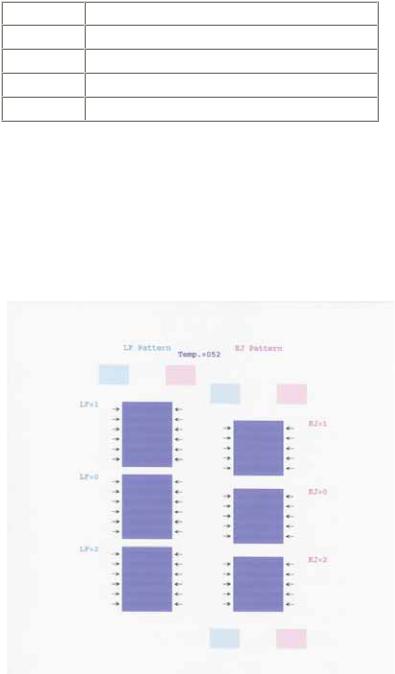
Details: Print the LF / Eject correction pattern on a sheet of paper. Select the Pattern No. (0 to 2) in which streaks or lines are the least noticeable, press the Resume/Cancel button the same number of time(s) as the selected Pattern No., then press the Power button. (See the flowchart below.)
1)In the LF /Eject correction mode, press the Resume/Cancel button the specified number of time(s) according to the paper to be used in LF / Eject correction listed in the table below, then press the Power button. (Set a sheet of selected paper in the ASF.)
Time(s) (L) |
|
Paper |
1 time |
|
HR-101 |
2 times |
|
GF-500, Office Planner |
3 times |
|
HP BrightWhite |
4 times |
|
Canon Extra, STEINBEIS |
Note: - Each time the Resume/Cancel button is pressed, the Alarm and Power LEDs light alternately, Alarm in orange and Power in green.
-If the Resume/Cancel button is NOT pressed, and only the Power button is pressed, the printer remains in the LF / Eject correction mode.
-If the Resume/Cancel button is pressed 5 times or more, then the Power button is pressed, the printer returns to the service mode menu selection.
2)The LF / Eject correction pattern for the selected paper is printed. (LF correction values from 0 to 2, Eject correction values from 0 to 2)
1-22

3)In the printout, select the Pattern No. in which streaks or lines are the least noticeable, press the Resume/Cancel button the same number of time(s) as the selected Pattern No., then press the Power button.
3-1) LF correction value
Selected pattern number
1
0
2
Number of times the Resume/Cancel button is pressed (M)
1time
0times
2times
Note: - Each time the Resume/Cancel button is pressed, the Alarm and Power LEDs light alternately, Alarm in orange and Power in green.
- If the Resume/Cancel button is pressed 3 times or more, then the Power button is pressed, the printer returns to the service mode menu selection.
3-2) Eject correction value
Selected pattern number
1
0
2
Number of times the Resume/Cancel button is pressed (N)
1time
0times
2times
Note: - Each time the Resume/Cancel button is pressed, the Alarm and Power LEDs light alternately, Alarm in orange and Power in green.
- If the Resume/Cancel button is pressed 3 times or more, then the Power button is pressed, the printer returns to the service mode menu selection.
1-23
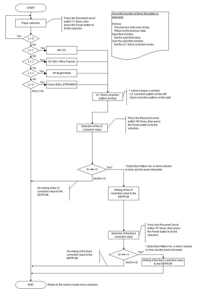
4)The selected LF correction value or Eject correction value is written to the EEPROM. The printer returns to the service mode menu selection after the correction values are written to the EEPROM.
1-24
 Loading...