


Broan 655, 657 User Manual
MODEL 655/659 HEATER/FAN/LIGHT
MODEL 657 FAN/LIGHT
655F, 657F AND 659F FINISH PACKS FOR
USE WITH 654H HOUSING PACKS
MODELO 655/659 CALENTADOR/VENTILADOR/LUZ
MODELO 657 VENTILADOR/LUZ
PAQUETES DE ACABADO 655F, 657F, Y 659F PARA
USAR CON PAQUETES DE BASTIDOR 654H
READ AND SAVE
THESE INSTRUCTIONS
WARNING
TO REDUCE THE RISK OF FIRE, ELECTRIC
SHOCK, OR INJURY TO PERSONS, OBSERVE THE
FOLLOWING:
1. Installation work and electrical wiring must be done
by qualified person(s) in accordance with all applicable codes and standards, including fire-rated
construction.
2. THIS PRODUCT MUST BE GROUNDED.
UNITS WITH HEATERS ONLY:
3. Do not use this unit with any solid-state speed
control device.
4. The combustion air flow needed for safe operation of fuel-burning equipment may be affected by
this unit's operation. Follow the heating equipment
manufacturer's guideline and safety standards
such as those published by the National Fire Protection Association (NFP A), and the American Society for Heating, Refrigeration and Air Conditioning Engineers (ASHRAE), and the local code authorities.
5. When cutting or drilling into wall or ceiling, do not
damage electrical wiring and other hidden utilities.
6. Ducted fans must always be vented to the outdoors.
UNITS WITH HEATERS ONLY:
7. Do not install this unit in a tub or shower enclosure.
8. Never place a switch where it can be reached from
a tub or shower.
9. Use this unit only in the manner intended by the
manufacturer. If you have questions, contact the
manufacturer.
10.Before servicing or cleaning unit, switch power off
at service panel and lock service panel to prevent
power from being switched on accidentally.
CAUTION
UNITS WITH HEATERS ONLY:
1. Provide a separate 15 AMP circuit. Use 14 GA.
power cable of type which meets code. (Separate 20 AMP circuit and 12 GA. wire for Model
655.)
2. This product is designed for ceiling installation
only. This product is designed for installation in
ceilings up to a12/12 pitch. Ductwork must point
up. DO NOT MOUNT THIS PRODUCT IN A
WALL.
3. Install in ceiling only, at least 6" from any wall.
4. For greatest efficiency, install heater so heat is
directed toward tub or shower area. Avoid directing toward walls or windows.
Models 657 & 657F ONLY:
5. Acceptable for use over a bathtub or shower
when installed in a GFCI protected branch
circuit.
6. For general ventilating use only . Do not use to exhaust hazardous or explosive materials and vapors.
7. To avoid motor bearing damage and noisy and/or
unbalanced impellers, keep drywall spray, construction dust, etc., off power unit.
8. Please read specification label on product for further information and requirements.
FIG. 1
RETAINING
SCREWS
TORNILLOS
DE RETEN
FIG. 2
FIG. 3
FIG. 4
FIG. 5
HINGE PIN
PASADORE DE
LA BISAGRA
KNOCKOUTS
DISCOS
REMOVIBLES
LEA Y CONSERVE
ESTAS INSTRUCCIONES
ADVERTENCIA
PARA REDUCIR EL RIESGO DE INCENDIO, DESCARGA
ELECTRICA O LESIONES PERSONALES, CUMPLA CON
LOS SIGUIENTES PUNTOS:
1. El trabajo de instalación y el cableado eléctrico deben de
llevarse a cabo por personal competente de acuerdo con
todos los códigos y las normas correspondientes,
incluyendo los códigos y normas de construcción a prueba
de incendios.
2. ESTE PRODUCTO DEBE SER CONECTADO A TIERRA.
SOLAMENTE PARA UNIDADES CON CALENTADOR:
3. No utilice esta unidad con aparatos de estado sólido
de control de velocidad.
4. El flujo de aire para la combustión necesario para el
funcionamiento seguro de equipo que quema combustible
puede ser afectado por el funcionamiento de esta unidad.
Siga las especificaciones del fabricante del equipo de
calefacción y las normas de seguridad semejantes a las
publicadas por la Asociación Nacional de Protección
Contra Incendios (NFPA por sus siglas en inglés), y la
Sociedad Americana de Ingenieros de Calefacción,
Refrigeración y Aire Acondicionado (ASHRAE), y los
códigos de las autoridades locales.
5. Cuando corte o taladre en una pared o cielo raso, no dañe
los cables eléctricos ni otras instalaciones no visibles.
6. Los ventiladores con conductos siempre deben ventilar
hacia el exterior.
SOLAMENTE PARA UNIDADES CON CALENTADOR:
7. No instale esta unidad sobre una bañera o ducha.
8. Nunca coloque un interruptor donde pueda ser alcanzado
desde la bañera o la ducha.
9. Solamente use esta unidad de la manera propuesta por
el fabricante. Si tiene alguna pregunta, póngase en
contacto con el fabricante.
10. Antes de limpiar o reparar la unidad, corte la potencia en
el panel de servicio y asegúrelo para evitar que resuma
accidentalmente.
PRECAUCIÓN
SOLAMENTE PARA UNIDADES CON CALENTADOR:
1. Provea un circuito por separado de 15 AMP. Use un
cable de potencia 14 GA. del tipo conforme al código
(circuito por separado de 20 AMP y cable de 12 GA.
para el modelo 655).
2. Este producto está diseñado solamente para instalarse
en el cielo raso. Este producto está diseñado para
instalarse en cielos rasos con una pendiente de hasta
12/12. El sistema de conductos debe apuntar hacia
arriba. NO MONTE ESTE PRODUCTO EN LA P ARED.
3. Instalar en el techo solamente por lo menos a 6" de la
pared.
4. Para asegurar una mayor eficiencia, instale el
calentador de manera que el calor esté dirigido hacia
el área de la bañera o ducha. Evite dirigir el calor hacia
paredes o ventanas.
SOLAMENTE MODELOS 657 y 657F:
5. Aceptable si se lo usa por encima de una tina o ducha
instaladas en un circuito derivado protegido GFCI (con
interruptor accionado por corriente de pérdida a tierra).
6. Solamente para uso de ventilación general. No use para
ventilar materiales y vapores peligrosos o explosivos.
7. Para evitar daños al cojinete del motor y/o impulsores ruidosos
o desequilibrados, mantenga la fuente de potencia lejos de
rocíos de yeso, de polvo de construcción, etc.
8. Lea la etiqueta de especificaciones del producto para más
información y requisitos.
INSTALLER: Leave This Manual With The Homeowner. HOMEOWNER: Use and Care Information on Page 3.
INSTALADOR: Deje este manual con el dueño de casa. DUEÑO DE CASA: Información del uso y mantenimiento en la página 3.
PREPARE THE UNIT
STEPS 1 THRU 3 - UNITS WITH HEATERS ONLY
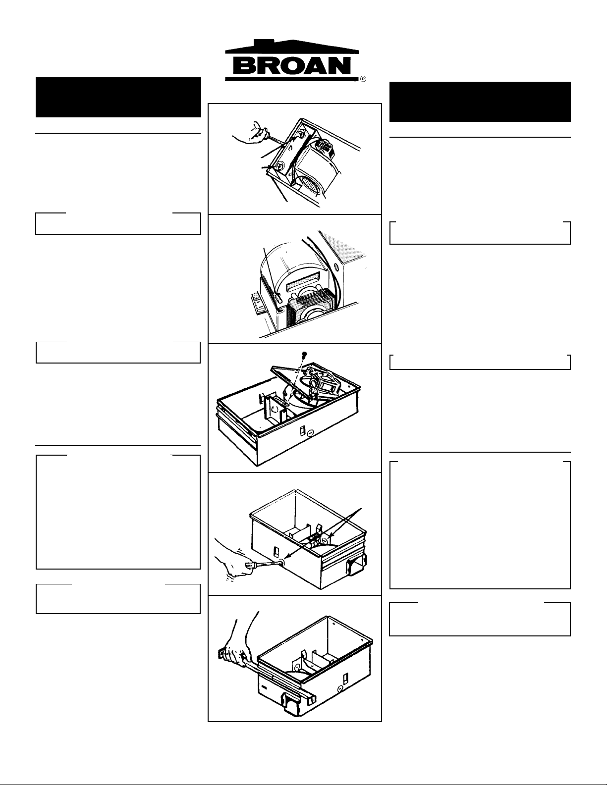
1. Make sure the heater assembly is unplugged
from the RED receptacle.
2. Loosen the two black retaining screws on the
inside of the heater discharge opening.
Place a screwdriver tip between the outer wall
of the discharge opening and the fan housing.
Gently pry outward until the exhaust discharge
slips off the support lip on the outer housing.
(FIG. 1)
3. Unhook hinge pins and lift heater assembly out
of housing. (FIG. 2)
4. Unplug the fan assembly from the BLACK receptacle. Remove the plastic bag and set it aside.
5. Remove the mounting screw and carefully lift the
fan assembly out of the housing. (FIG. 3)
6. Refer to the wiring diagram of your unit on the next
page. Remove appropriate knockout(s) by inserting a screwdriver blade into slots and bending it
back and forth to break tabs. (FIG. 4)
7. Insert the adjustable mounting brackets into the
bracket channels on the housing. (FIG. 5)
INSTALL THE UNIT
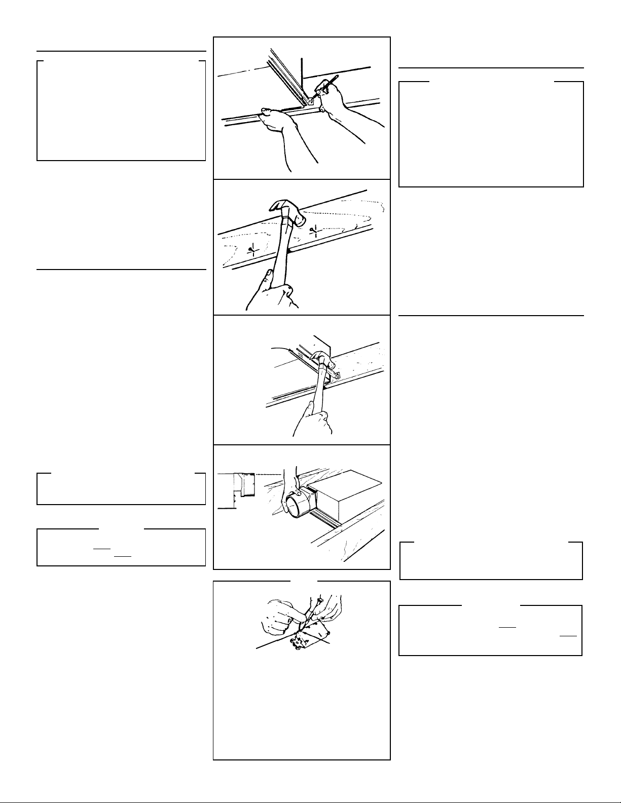
8. For best results, choose a location which allows
fan to be vented outside with the shortest possible
duct run and the fewest number of elbows.
9. Position unit between joists and extend mounting
brackets. Position brackets such that the bottom
edge of housing will be flush with finished ceiling.
Mark the top of keyhole slot on all four mounting
brackets. (FIG. 6)
10.Remove unit temporarily, and pound nails partially
into joists at all four marked locations. (FIG. 7)
11.Hang unit from nails and use embossed measuring guides to check if unit will be flush with finished ceiling. Pound nails tight. For wide joist
centers: A #8 x 3/8 self-tapping screw can be used
to join extended brackets together and create a
rigid mount. To ensure a noise-free mount, crimp
the bracket channels tightly around mounting
brackets. (FIG. 8)
12. Snap the damper/duct connector onto housing.
Make sure that tabs on the connector lock in housing slots. (Top of damper/duct connector will be
flush with top of housing.) (FIG. 9)
13.Wire unit according to Figure 10 or 11, whichever
is appropriate. (See NOTE.)
STEP 14 - UNITS WITH HEATERS ONLY
14. Replace heater assembly removed in STEP 3
and plug it into RED receptacle. Direct wires
away from blower inlet.
15. Replace fan assembly removed in STEP 5 and plug
it into BLACK receptacle.
To avoid the possibility of overheating and/or
grille
fire, the
FIG. 12.
rod
through proper hole in
16. Slide the light reflector into opening in grille and
plug into WHITE receptacle. Use acorn nut from
plastic bag to attach grille reflector assembly to
threaded rod on housing. Tighten securely using
pliers or nut driver. Install a light bulb 100 Watt
maximum. (FIG.. 12)
17.Install light lens by 1) hooking one of its tabs into
notch in grille/reflector assembly; 2) apply light
pressure to other tab with fingertips and 3) snap
into place. (FIG. 13)
CAUTION
must be installed as shown in
Acorn nut
must attach to
light reflector.
threaded
FIG. 6
FIG. 7
FIG. 8
EMBOSSED
MEASURING
GUIDES
GUIAS
ESTAMPADAS
DE MEDICION
FIG. 9
FLUSH
NIVEL
NOTE
NOTA
WIRE
OPENING
ENTRADA
PARA
EL CABLE
If the switch has not been wired properly and wires need
to be moved:
1. Each wire opening has a release slot.
2. Push a small nail or screwdriver into release slot while gently
removing wire.
3. DO NOT pull any wire out of the switch without using the
release slot. The switch may be damaged.
Si el interruptor no ha sido conectado de forma apropiada
y se necesita cambiar los cables:
1. Cada entrada para cable posee una ranura de desenganche.
2. Meta un clavo pequeño o un destornillador en la ranura de
desenganche mientras saca el cable poco a poco.
3. NO tire de los cables hacia afuera del interruptor sin usar la
ranura de desenganche. Esto puede dañar el interruptor.
2
RELEASE SLOT
RANURA DE
DESENGANCHE
PREP ARACION
DE LA UNIDAD
PASOS DEL 1 AL 3 - SOLO PARA
UNIDADES CON CALENTADORES
1. Asegúrese de que el conjunto del calentador está
desconectado del enchufe ROJO.
2. Afloje los dos tornillos negros de retén en el interior de
la abertura de descarga del calentador. Coloque la punta
del destornillador entre la pared exterior de la abertura
de descarga y la caja del ventilador. Haga palanca
suavemente hacia afuera hasta que la abertura del
escape se deslice del borde de apoyo en la caja exterior.
(FIG. 1)
3. Desenganche los pasadores de la bisagra y levante el
conjunto del calentador hacia afuera de la caja. (FIG.
2)
4. Desconecte el conjunto del ventilador del enchufe
NEGRO. Saque la bolsa de plástico y déjela a un lado.
5. Saque el tornillo de montaje y levante con cuidado el
conjunto del ventilador hacia afuera de la caja. (FIG. 3)
6. Refiérase al diagrama de conexiones de la unidad en la
página siguiente. Saque los discos removibles apropiados
introduciendo la punta del destornillador en las ranuras y
moviendo éste de un lado a otro hasta romper las
lengüetas. (FIG. 4)
7. Meta los soportes de montaje ajustables en los canales
para los soportes en la caja. (FIG. 5)
INSTALACION
DE LA UNIDAD
8. Para mejores resultados, elija una posición que permita
que el ventilador extraiga hacia afuera usando la menor
cantidad de ducto y el menor número posible de codos.
9. Coloque la unidad entre las vigas y extienda los soportes
de montaje. Coloque los soportes de manera que el
extremo inferior de la caja esté al nivel del cielo raso
acabado. Marque la parte superior de la ranura en los
cuatro soportes de montaje. (FIG. 5)
10. Saque la unidad por unos momentos, y clave los clavos
parcialmente en las vigas en las cuatro posiciones
marcadas. (FIG. 7)
11. Cuelgue la unidad de los clavos y use las guías de
medición estampadas para comprobar si la unidad se
encuentra a nivel con el cielo raso acabado. Termine de
clavar los clavos. En caso de que el centro de las vigas
sea ancho: se puede usar un tornillo autoenroscante # 8
x 3/8 para juntar los soportes extendidos y crear un soporte
de montaje rígido. Para asegurar un montaje silencioso,
pliegue los canales alrededor de los soportes de montaje.
(FIG. 8)
12. Meta la conexión del amortiguador/ducto en la caja.
Asegúrese de que las lengüetas del conector se cierran
en las ranuras de la caja.(La parte superior del
amortiguador/ducto debe estar a nivel con la parte superior
de la caja). (FIG. 9)
13. Conecte la unidad de acuerdo con el diagrama de las
figuras 10 y 11. (See NOTE.)
PASO 14 - SOLO PARA UNIDADES CON
14. Vuelva a colocar el conjunto del calentador que se sacó
en el paso 3 y conéctelo al enchufe ROJO. Instale los
alambres alejados de la entrada de aire el ventilador.
15. Vuelva a colocar el conjunto del ventilador que se sacó
en el paso 5 y conéctelo al enchufe NEGRO.
Para evitar la posibilidad de un sobrecalentamiento
y/o un incendio, la
muestra en la figura 12. La tuerca ciega debe
conectarse a la varilla roscada a través del agujero
apropiado en el reflector de luz.
16. Deslice el reflector de luz en la abertura de la rejilla y
conéctelo al enchufe BLANCO. Use la tuerca en la bolsa
de plástico para sujetar la rejilla y el reflector de luz a la
varilla roscada de la caja. Apriete con fuerza usando el
alicates o el aprietatuercas. Instale una bombilla de un
máximo de 100 vatios. (FIG. 12)
17. Para instalar el lente de la luz: 1) Enganche una de las
lengüetas en la muesca del conjunto rejilla/reflector; 2)
Aplique un poco de presión a la otra lengûeta con los
dedos, y 3) Encájela en su sitio. (FIG. 13)
CALENTADORES
PRECAUCION
rejilla
debe ser instalada se
 Loading...