


Broan ALT330SS Installation Manual

WWW.BROAN.COM
WWW.BROAN.CA
RANGE HOOD
Series: ALT3
INSTALLATION, USE
AND CARE MANUAL
Serial number:
99046186A

Safety . . . . . . . . . . . . . . . . . . . . . . . . . . . . . . . . . 3-4
Operation . . . . . . . . . . . . . . . . . . . . . . . . . . . . . . 5-6
Cleaning and Maintenance . . . . . . . . . . . . . . . . . 7
Motors
Grease Filters
Non-Ducted Recirculation Filters
Fan Wheels
Stainless Steel Cleaning
Installation . . . . . . . . . . . . . . . . . . . . . . . . . . . . 8-20
Recommended Tools
and Accessories for Installation . . . . . . . . . . . . 8
Install Ductwork (Ducted Installations Only) . . . 8
Contents . . . . . . . . . . . . . . . . . . . . . . . . . . . . . . 9
Prepare the Hood . . . . . . . . . . . . . . . . . . . . . . . 10-12
Prepare the Hood Location . . . . . . . . . . . . . . . . 13
EZ1 Person Installation . . . . . . . . . . . . . . . . . 13-15
Install the Hood (EZ1 Bracket) . . . . . . . . . . . . 16-17
Standard Installation . . . . . . . . . . . . . . . . . . . 18
Install the Hood (Standard Installation) . . . . . 19
Connect the Wiring . . . . . . . . . . . . . . . . . . . . . . 20
Install the Filters . . . . . . . . . . . . . . . . . . . . . . . . 20
Wiring Diagram . . . . . . . . . . . . . . . . . . . . . . . . . 21
Service Parts . . . . . . . . . . . . . . . . . . . . . . . . . . . 22
Warranty . . . . . . . . . . . . . . . . . . . . . . . . . . . . . . . 23
INSTALLATION MANUAL
TABLE OF CONTENTS
2
READ AND SAVE THESE INSTRUCTIONS
!
Intended for domestic cooking only
!
INSTALLER: LEAVE THIS MANUAL WITH HOMEOWNER.
In U.S.A., register your range hood online at www.broan.com.
In Canada, register your range hood online at www.broan.ca.
!
WARNING
TO REDUCE THE RISK OF FIRE, ELECTRIC SHOCK, OR INJURY TO
PERSONS, OBSERVE THE FOLLOWING:
• Use this unit only in the manner intended by the manufacturer. If you have
questions, contact the manufacturer at the address or telephone number
listed in the warranty.
• Before servicing or cleaning unit, switch power off at service panel and
lock the service disconnecting means to prevent power from being
switched on accidentally. When the service disconnecting means cannot
be locked, securely fasten a prominent warning device, such as a tag, to
the service panel.
• Installation work and electrical wiring must be done by a qualified
person(s) in accordance with all applicable codes and standards, including
fire-rated construction.
• Sufficient air is needed for proper combustion and exhausting of
gases through the flue (chimney) of fuel burning equipment to prevent
backdrafting. Follow the heating equipment manufacturer’s guidelines and
safety standards such as those published by the National Fire Protection
Association (NFPA) and the American Society for Heating, Refrigeration
and Air Conditioning Engineers (ASHRAE) and the local code authorities.
• When cutting or drilling into wall or ceiling, do not
damage electrical wiring and other hidden utilities.
• Ducted fans must always be vented to the outdoors.
• Do not use this unit with any additional solid-state speed control device.
• To reduce the risk of fire, use only metal ductwork.
• This unit must be grounded.
• As an alternative, this product may be installed with the UL-approved cord
kit designated for the product, following instructions packed with the cord
kit.
• When applicable local regulations comprise more restrictive installation
and/or certification requirements, the aforementioned requirements prevail
on those of this document and the installer agrees to conform to these at
his own expense.
INSTALLATION MANUAL
SAFETY
3

!
WARNING
TO REDUCE THE RISK OF A RANGE TOP GREASE FIRE:
a) Never leave surface units unattended at high settings. Boilovers cause
smoking and greasy spillovers that may ignite. Heat oils slowly on low or
medium settings.
b) Always turn hood ON when cooking at high heat or when flambeing food
(i.e.: Crêpes Suzette, Cherries Jubilee, Peppercorn Beef Flambé).
c) Clean ventilating fan frequently. Grease should not be allowed to
accumulate on fan, filters or in exhaust ducts.
d) Use proper pan size. Always use cookware appropriate for the size of
the surface element.
TO REDUCE THE RISK OF INJURY TO PERSONS IN THE EVENT OF A
RANGE TOP GREASE FIRE, OBSERVE THE FOLLOWING*:
1. SMOTHER FLAMES with a close-fitting lid, cookie sheet or metal tray,
then turn off the burner. BE CAREFUL TO PREVENT BURNS. IF THE
FLAMES DO NOT GO OUT IMMEDIATELY, EVACUATE AND CALL
THE FIRE DEPARTMENT.
2. NEVER PICK UP A FLAMING PAN — You may be burned.
3. DO NOT USE WATER, including wet dishcloths or towels — This could
cause a violent steam explosion.
4. Use an extinguisher ONLY if:
A. You own a Class ABC extinguisher and you know how to operate it.
B. The fire is small and contained in the area where it started.
C. The fire department has been called.
D. You can fight the fire with your back to an exit.
* Based on “Kitchen Fire Safety Tips” published by NFPA.
INSTALLATION MANUAL
SAFETY
4
!
CAUTION
• For indoor use only.
• For general ventilating use only. Do not use to exhaust hazardous or explosive materials
and vapors.
• To avoid motor bearing damage and noisy and/or unbalanced fan blade, keep drywall
spray, construction dust, etc. off range hood.
• Your hood motor has a thermal overload which will automatically shut off the motor if it
becomes overheated. The motor will restart when it cools down. If the motor continues to
shut off and restart, have the hood serviced.
• For best capture of cooking fumes, the bottom of the hood MUST NOT BE LESS than 18”
and at a maximum of 30” above the cooking surface.
• Always follow the cooking equipment manufacturer’s requirements regarding the ventilation
needs.
• To reduce the risk of fire and to properly exhaust air, be sure to duct air outside — Do not
exhaust air into spaces within walls or ceiling or into attics, crawl space or garage.
• When installing, servicing or cleaning the unit, it is recommended to wear safety glasses
and gloves.
• Please read specification label on product for further information and requirements.
Operation
Always turn your hood on before you begin cooking to establish an air flow in the kitchen.
Let the blower run for a few minutes to clear the air after you turn off the range. This will help
keep the whole kitchen cleaner and fresher.
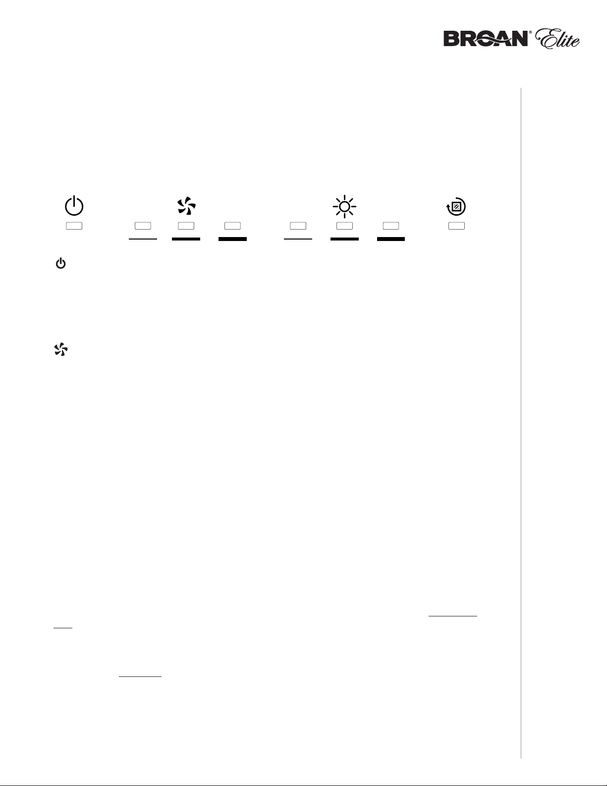
This hood is equipped with infrared sensing controls. To activate it, simply touch the sensor
corresponding to the desired function and/or intensity. At the touch of the sensor, a beep is
emitted to acknowledge the command.
MASTER ON/OFF
Touch this sensor to turn ON the lights and blower at the last saved blower and/or lighting level.
When the blower and/or lights are ON, touching this sensor will store the last-used blower speed
and light intensity and turn the unit off.
BLOWER
ACTIVATION/SPEED CHANGE
When blower is OFF, touch the sensor corresponding to the desired blower speed. The sensor will
illuminate and the blower will activate.
When the blower is ON, touch the sensor corresponding to the active blower speed to turn the
blower OFF and memorize the blower speed.
NOTE: When LOW speed is activated from OFF, the blower starts on MEDIUM speed for a very
short moment, and then resumes to LOW speed.
DELAY OFF
To activate the Delay OFF function, while the blower is ON, touch and hold for 3 seconds the
illuminated sensor corresponding to the active blower speed. A beep will be emitted at the first
touch, and again at the end of the 3-second hold. The blower will continue to operate for 10minutes
at this setting. During this time, the sensor corresponding to the active blower speed will blink to
indicate that the Delay OFF function was activated.
When the Delay OFF function is activated, the blower speed can be changed by touching the
sensor corresponding to the desired blower speed without affecting the remaining time of the delay.
To cancel the Delay OFF function before the end of the 10-minute cycle, touch and hold for
3seconds the sensor corresponding to the active blower speed, or simply touch the Master ON/OFF
sensor.
HEAT SENTRY™
This hood is equipped with a protective device that changes the blower speed when an abnormally
high heat level is detected while the blower is activated. When the Heat Sentry is activated, it sets
the blower on MEDIUM speed while all the blower sensors blink. The lighting can still be controlled,
but the blower will remain on MEDIUM speed until the heat level is normal. The blower will then
return to the speed previously selected.
NOTE: When excessive heat is detected, Heat Sentry will shut off both the blower and lights
while all the blower sensors will blink faster. Both the blowers and lights will remain OFF
until the temperature cools down; the blower will then start on MEDIUM speed and the
lights can be controlled again. The blower will remain on MEDIUM speed until the heat
level is normal. The blower will then return to the speed previously selected.
OPERATION
INSTALLATION MANUAL
5

LIGHTING/LIGHT INTENSITY CHANGE
To turn the lighting ON, touch the sensor corresponding to the desired lighting intensity and the
sensor will illuminate.
When the lighting is ON, touch the sensor corresponding to the active light intensity to turn the
lighting OFF and memorize the intensity.
The LED modules included with this hood are the latest in LED cooktop illumination technology
specially designed to operate in the elevated temperatures of cooking - offering bright lighting and
lasting up to 25 times as long as a standard bulb and greater reliability than typical replacement
LED bulbs.
FILTER CLEANING REMINDER
When it is time to clean the filters, the Filter Cleaning Reminder sensor will blink for 30seconds
after the blower is turned off.
To reset the Filter Cleaning Reminder, touch and hold for 3seconds this sensor while it is blinking.
ADDITIONAL INFORMATION
This control is light-sensitive; pointing directional spot lights towards it may cause it to malfunction.
In rare circumstances, the control could falsely be activated by an external light source.
OPTIONAL REMOTE CONTROL
For more convenience, the ALT3 Series range hood can also be controlled using the HCR3 remote
control (purchase separately). For more details, see instructions included with the HCR3 remote
control.
INSTALLATION MANUAL
OPERATION
6

Cleaning and Maintenance
Proper maintenance of the Range Hood will assure proper performance of the unit.
MOTORS
The motors are permanently lubricated and never need oiling. If the motor bearings make
excessive or unusual noise, replace the motor with the exact service motor. The fan wheel should
also be replaced.
GREASE FILTERS
The grease filters should be cleaned frequently. Use a warm dishwashing detergent solution.
Grease filters are diswasher safe. Clean all-metal filters in the dishwasher using a non-phosphate
detergent. Discoloration of the filters may occur if using phosphate detergents, or as a result of
local water conditions - but this will not affect filter performance. This discoloration is not covered
by the warranty. To minimize or prevent discoloration, hand wash filters using a mild detergent.
NON-DUCTED RECIRCULATION FILTERS
The non-ducted recirculation filters should be changed every 3 to 6 months. Replace more often
if your cooking style generates extra grease, such as frying and wok cooking. Refer to installation
instructions included with non-ducted recirculation filters.
FAN WHEELS
The center of the fan wheels should be cleaned frequently. Use a clean cloth soaked with warm
detergent solution.
STAINLESS STEEL CLEANING
CLEANING AND MAINTENANCE
Do:
• Regularly wash with clean cloth or rag soaked with warm water and mild soap or liquid dish
detergent.
• Always clean in the direction of original polish lines.
• Always rinse well with clear water (2 or 3 times) after cleaning. Wipe dry completely.
• You may also use a specialized household stainless steel cleaner.
Don’t:
• Use any steel or stainless steel wool or any other scrapers to remove stubborn dirt.
• Use any harsh or abrasive cleansers.
• Allow dirt to accumulate.
• Let plaster dust or any other construction residues reach the hood. During construction/
renovation, cover the range hood to make sure no dust sticks to the stainless steel surface.
Avoid when choosing a detergent:
• Any cleaners that contain bleach will attack stainless steel.
• Any products containing: chloride, fl uoride, iodide, bromide will deteriorate surfaces
rapidly.
• Any combustible products used for cleaning such as acetone, alcohol, ether, benzol, etc.,
are highly explosive and should never be used close to a range.
INSTALLATION MANUAL
7

For ADA compliance installation guidelines, please visit www.broan.com
Recommended Tools and Accessories
for Installation
• Measuring tape
• Phillips screwdriver no. 2
• Nutdriver or socket 11/32"
• Flat blade screwdriver (to open knockout holes)
• Drill, 1/8” drill bit and 1½” hole saw (to mark holes for ducting and cut electrical access hole)
• 7/64” drill bit (to drill holes for EZ1 brackets mounting screws)
• Wood shims (2) and wood screws (4) (required for standard installation to framed cabinet)
• Saw (to cut holes for ducted application)
• Sheet metal shears (ducted installation only, for duct adjustment)
• Pliers (ducted installation only, for duct adjustment)
• Metal foil duct tape (for ducted applications)
• Scissors (to cut metal foil duct tape)
• Pencil
• Wire stripper
• Strain relief, 1/2” diameter (to secure house wiring cable to the hood)
INSTALLATION MANUAL
INSTALLATION
Install Ductwork (Ducted Installations Only)
ROOF CAP
SOFFIT
CABINET
HOOD
18" MIN - 30" MAX
ABOVE
COOKING SURFACE
NOTE: Distances over 30” are at the installer and user discretion.
1 ] Determine whether hood will discharge vertically (3¼” x 10” or 7” round),
or horizontally (3¼” x 10” only).
2 ] Decide where the ductwork will run between the hood and the outdoors.
3 ] Choose a straight, short duct run to allow the hood to perform most efficiently. Long duct
runs, elbows and transitions will reduce the performance of the hood. Use as few of them as
possible. When possible, use at least 2 foot straight runs before any turns. Larger ductwork
may be required for best performance with longer duct runs.
NOTE: To use 6” round ducting, install a 3¼” x 10” to 6” round transition (not included). The
performances may be affected.
4 ] Install wall cap or roof cap (sold separately); ensure there is no leak in house insulation.
Connect metal ductwork to cap and work back towards the hood location. Use 2” metal foil
duct tape to seal the joints between ductwork sections.
3¼" X 10" OR
7" ROUND DUCT
(FOR VERTICAL
DISCHARGE
HOUSE WIRING
(TOP OR BACK OF HOOD)
3¼" X 10" DUCT
(FOR HORIZONTAL DISCHARGE)
)
WALL CAP
8
Contents
VERTICAL EXHAUST
Before proceeding to the installation, check the contents of the box. If items are missing or
damaged, contact the manufacturer.
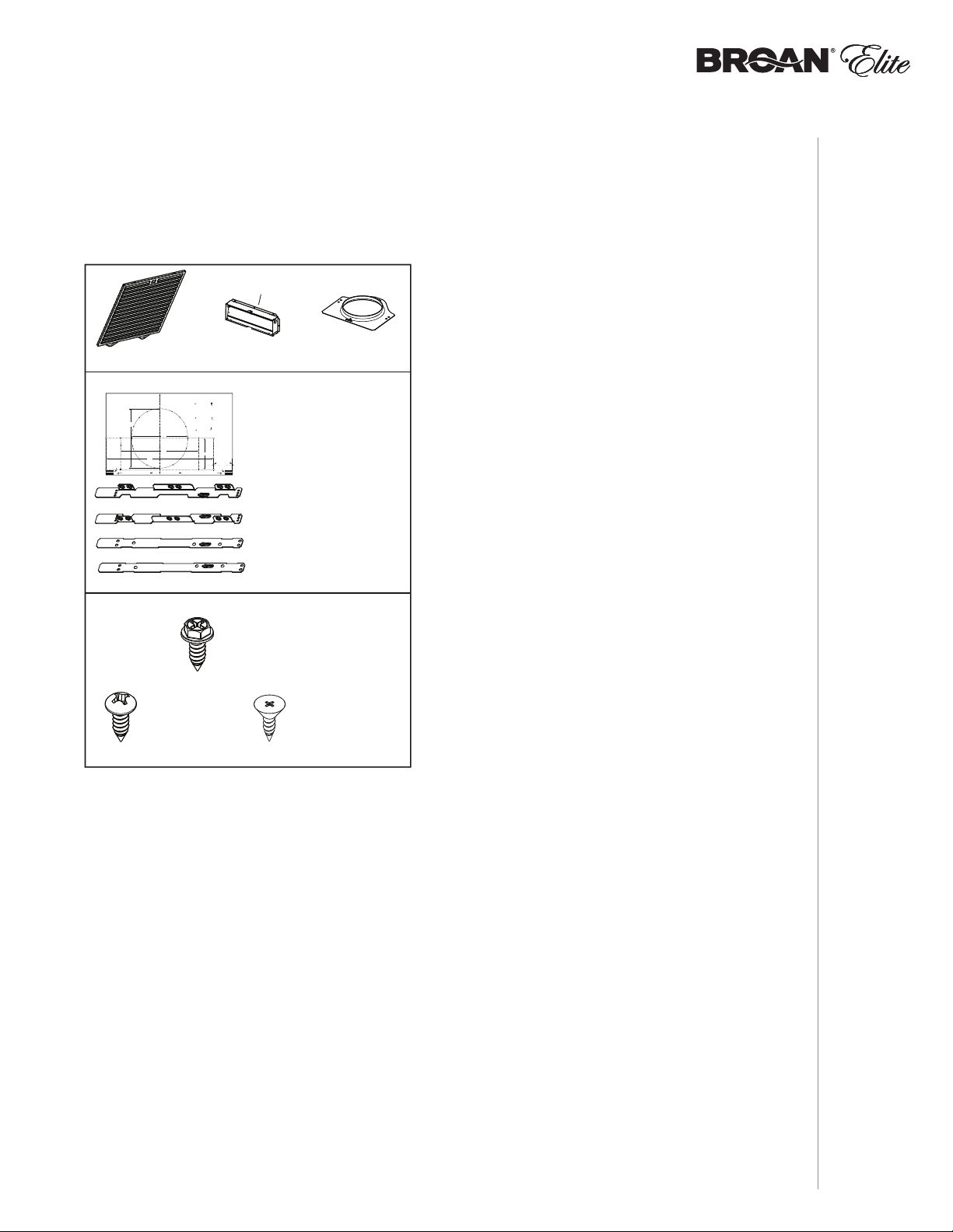
Make sure that the following items are included:
* FIND INSIDE ONE PACKAGING
STYROFOAM OF HOOD
(2) GREASE FILTERS
Use this template for marking;do not attempt to cut out the ducting hole through it.
NOTE: These cutouts are clearance holes; they do not need to be the exact size of ducting.
Utiliser ce gabarit pour marquer vos repères;ne pas tenter de découper
le trou pour le conduit à travers le gabarit.
NOTE : Les découpes incluent le jeu nécessaire à l’installation; elles ne doivent pas
être du format exact des conduits.
Use esta plantilla para crear marcados;no trate de cortar el
agujero del conducto a través de la plantilla.
NOTA: To be translated in Spanish.
Bend template along graduated
scale when installing to framed
cabinet.
C
Pour une installation sous une
armoire à fond en retrait, utiliser les
lignes pour mesurer l’épaisseur du
décalage causé par le mur de
l’armoire et plier le gabarit en
8”
conséquence.
To be translated in Spanish.
C
L
7½”
10½”
14½”
C
Appuyer ce bord au mur arrière
** FIND EZ1 BRACKETS ATTACHED INSIDE OF HOOD
(6) N
RD. HD.
W
OOD SCREWS
(1) 3¼” X 10”
D
AMPER ASSEMBLY*
EZ1 COMPONENTS
MARKWHEREINDICATED
FORTHEAPPROPRIATE SIZE DUCT OPENING
RECTANGULAR DUCTING7” ROUND DUCTING
OR
= 3¼” x 10”
= 3¼” x 14”
MARQUERLESREPÈRES AUX ENDROITS INDIQUÉSSELON
LEFORMATDE CONDUIT UTILISÉ
CONDUITRECTANGULAIRECONDUITRONDDE 7 PO
OU
= 3¼ po x 10 po
= 3¼ po x 14 po
TITLETOBE TRANSLATED IN SPANISH
CONDUCTORECTANGULARCONDUCTOREDONDO
O
= 3¼ pulg. x 10 pulg.
DE
7 PULG.
= 3¼ pulg. x 14 pulg.
4¼”
Apoyar este borde contra la pared de atrásPlace this edge against back wall
(1) TEMPLATE FOR DUCTING
Electrical access hole center
A = single blower hood
B = double blower hood
Centre du trou pour fil
d’alimentation électrique
A = hotte ventilateur simple
B = hotte ventilateur double
To be translated in Spanish
Electrical access hole center
A = single blower hood
B = double blower hood
AB
C
(PRINTED BOTH SIDES)
(2) INSTALLATION BRACKETS**
FOR FRAMED CABINET
(2) INSTALLATION BRACKETS**
FOR FRAMELESS CABINET
(1) P
ARTS BAG*** CONTAINING:
(4) NO. 8-18 X 1/2”
M
ETAL SCREWS
O. 8 X 5/8”
*** FIND PARTS BAG INSIDE OF HOOD
(1) 7” ROUND
DUCT CONNECTOR
(6) NO. 8 X 1/2”
C
OUNTERSUNK
WOOD SCREWS
INSTALLATION
INSTALLATION MANUAL
9

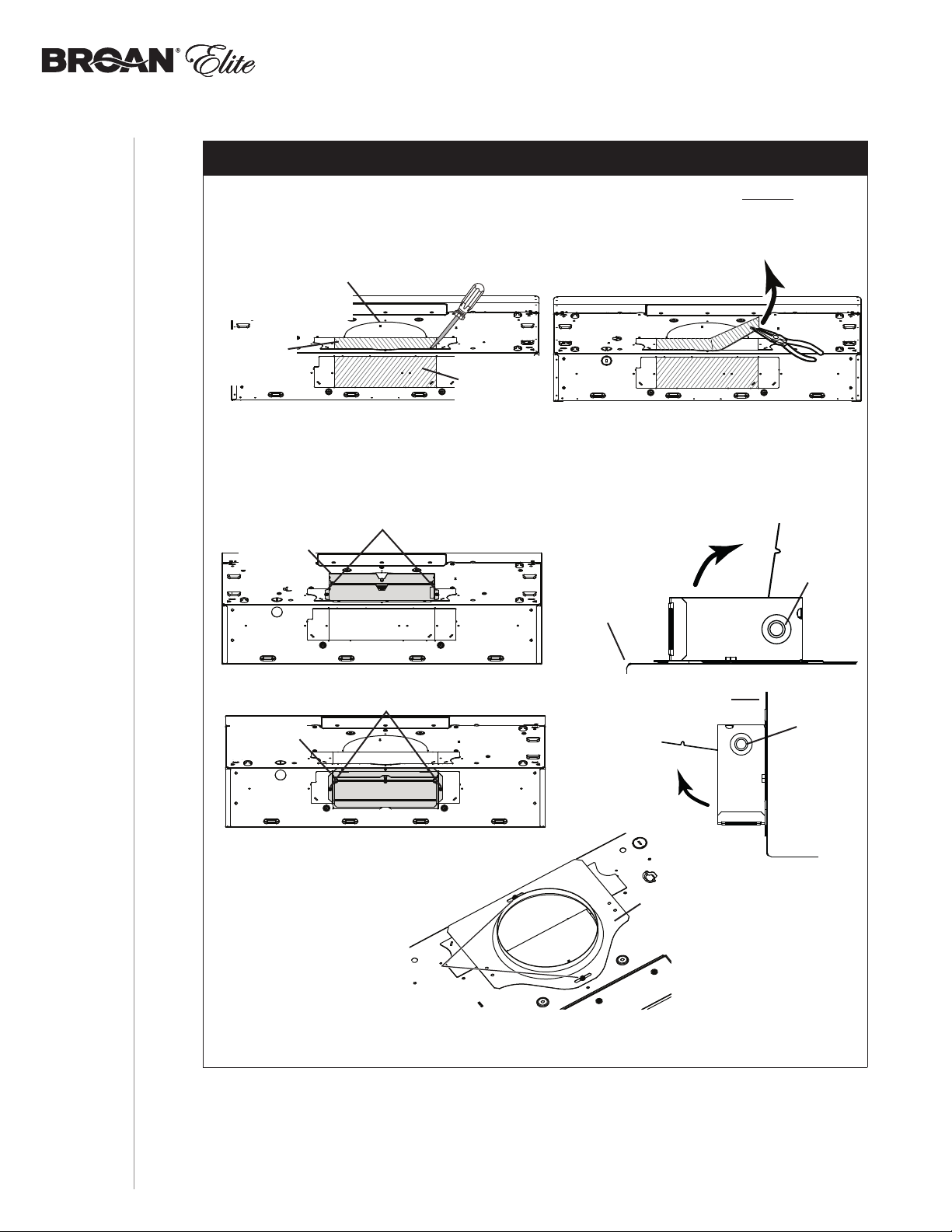
Prepare the Hood
1 ] If present, remove all protective polyfilm from the hood and/or parts.
2 ] Remove 7” Round Duct Plate from top/back of hood (see illustration below). Keep the screws
for further use.
7” ROUND
DUCT PLATE
2 SCREWS
3 ] Using the finger cup, remove the grease filters from the hood by pushing down and tilting
filters out .
INSTALLATION MANUAL
INSTALLATION
B
C
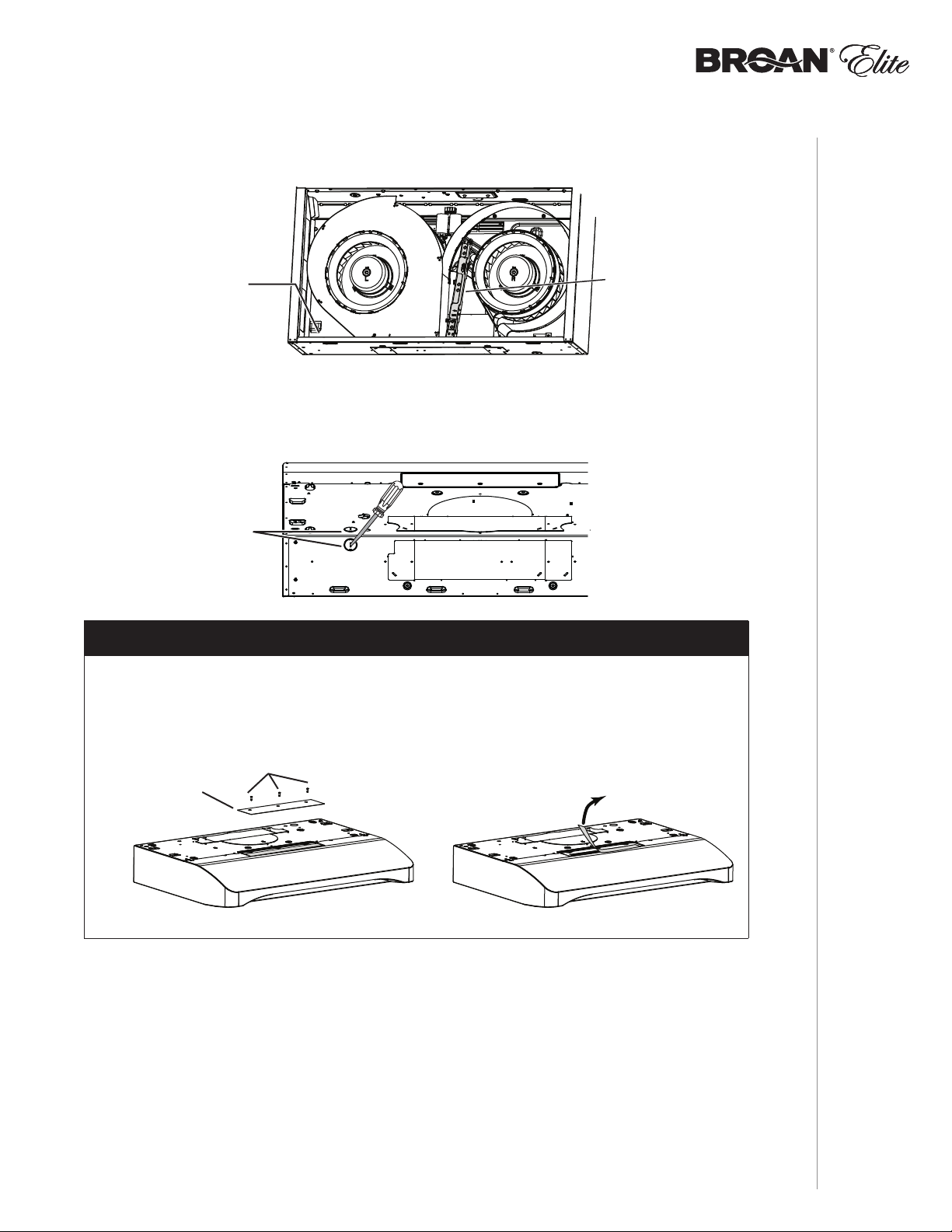
4 ] Using a 11/32” nutdriver or socket, remove the lock nut retaining the flange of the right cover
plate (shaded part on illustration below) to the inner back of hood (see inset). Remove the
right cover plate retaining screws (7 screws), then set the blower cover along with its screws
and nut aside.
45
3
6
2
7
BACK OF HOOD
LOCK NUT
1
10
5 ] Remove the parts bag, taped on the inner back of hood, near the left corner. Remove the
EZ1 brackets from inside the hood by cutting off the tie wrap. Discard the tie wrap.
PARTS BAG LOCATION
6 ] Remove Electrical Power Cable Knockout from top (vertical exhaust) or back (horizontal
exhaust) of hood. For knockout removed from back of hood, install an appropriate strain
relief, 1/2” diameter (not included). For knockout removed from top of hood, the strain relief
will be installed later.
ELECTRICAL
POWER CABLE
KNOCKOUT
EZ1
BRACKETS
NON-DUCTED INSTALLATION ONLY
7 ] Remove 3 screws retaining the recirculation cover plate to the hood. Discard this plate with
its screws. Peel off and discard the membrane covering the recirculation grille, ensuring
the openings are totally cleared.
RECIRCULATION
COVER PLATE
SCREWS
INSTALLATION
INSTALLATION MANUAL
11
DUCTED INSTALLATION ONLY
8 ] Remove 3¼” x 10” vertical, 3¼” x 10” horizontal (both are the rectangular central
knockout plates, see hatched areas) or 7-inch round knockout plate as appropriate for
your ducting method (see FIGURES 1 A and 1 B).
FIGURE 1 A
7” ROUND KNOCKOUT
PLATE (ALSO REMOVE
3¼” X 10” VERTICAL
KNOCKOUT PLATE)
3¼” X 10”
VERTICAL
KNOCKOUT
PLATE
3¼” X 10”
HORIZONTAL
KNOCKOUT
PLATE
9 ] Attach 3¼” x 10” Damper Assembly on top OR back of hood (if using 3¼” x 10” duct; shaded
part in FIGURE 2 A below) or 7” Round Duct Plate (if using 7-inch round duct, FIGURE 3) over
the knockout opening. When installed, the 3¼” x 10” damper assembly must open as shown
in FIGURE 2 B.
FIGURE 2 A FIGURE 2 B
3¼” X 10”
DAMPER
ASSEMBLY
SCREWS
FIGURE 1 B
TOP/BACK
EDGE OF
HOOD
DAMPER
FLAP
PIVOT
INSTALLATION MANUAL
INSTALLATION
SCREWS
3¼” X 10”
DAMPER
ASSEMBLY
FIGURE 3
SCREWS
BACK OF
HOOD
DAMPER
FLAP
PIVOT
7” ROUND
DUCT
PLATE
NOTE: To accommodate off-center ductwork, the 7” round duct plate can be installed up
to 1/2” on either side of the hood center.
TIP: Insert a small length of duct over the 3¼” x 10” damper assembly (for rectangular ducting) or
7” round (for round ducting) and seal the joint using aluminum foil duct tape to ease connection
with the house ductwork.
12
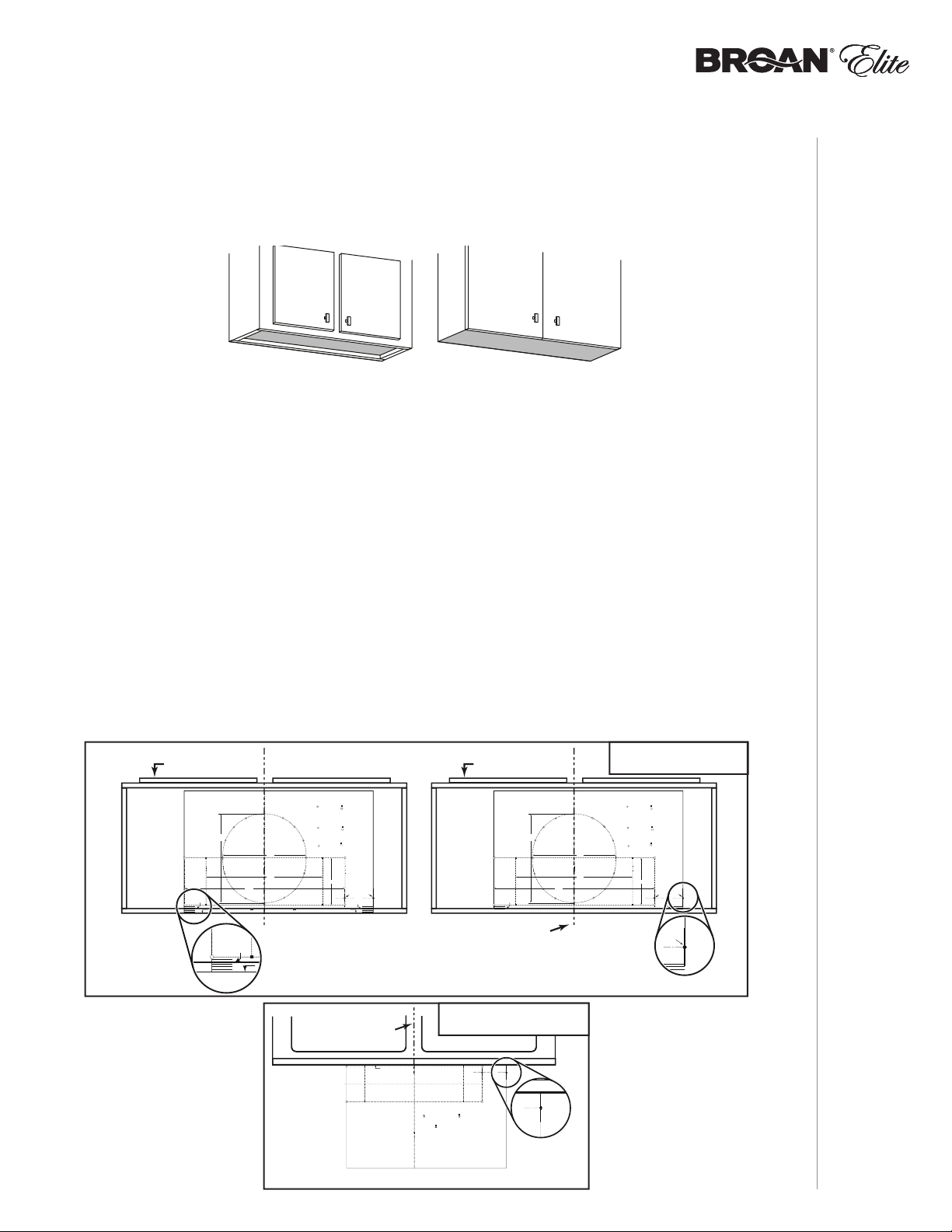
Prepare the Hood Location
VERTICAL EXHAUST
VERTICAL EXHAUST
NOTE: Before starting installation, read all the steps of these instructions.
Use the illustration below to identify your kitchen cabinet type.
FRAMED CABINET FRAMELESS CABINET
This manual covers 2 kinds of installation: the standard (without EZ1 brackets)
and the EZ1 one-person installation system (using included template and brackets).
For the standard installation, go to page 18.
EZ1 one-person installation system
EZ1 installation is designed for use with kitchen cabinets that have the same width designation as
the range hood width. If the cabinet is greater than 1/2” wider than the range hood width, please
use the standard installation method.
1 ] Use the proper template for vertical OR horizontal disharge (included) for placement of
ductwork and electrical cutout in cabinet or wall. For a non-ducted installation, DO NOT cut a
duct access hole, only cut the hole for electrical wiring. If replacing a hood and plan to use
the existing duct and electrical, steps 2 to 5 may not be necessary. If so, skip to step 6.
2 ] Measure and mark the hood center line on cabinet bottom.
3 ] Align the center line on template with the hood center line marked on the bottom of the
cabinet, placing the edge (where indicated) of the template against back wall. When using
with framed cabinet for vertical exhaust installation, fold over rear edge of template equal
to the depth of the cabinet frame at the wall (use graduations on template, C locations on
template). Tape the template in place.
NOTE: When facing the installation, A and B (on template) must be at right.
CABINET FRONT
CABINET FRONT
VERTICAL EXHAUST
DUCTING
Use this template for marking;do not attempt to cut out the ducting hole through it.
NOTE: These cutouts are clearance holes; they do not need to be the exact size of ducting.
Utiliser ce gabarit pour marquer vos repères;ne pas tenter de découper
le trou pour le conduit à travers le gabarit.
NOTE : Les découpes incluent le jeu nécessaire à l’installation; elles ne doivent pas
être du format exact des conduits.
Use esta plantilla para crear marcados;no trate de cortar el
agujero del conducto a través de la plantilla.
NOTA: To be translated in Spanish.
Bend template along graduated
scale when installing to framed
cabinet.
C
Pour une installation sous une
armoire à fond en retrait, utiliser les
lignes pour mesurer l’épaisseur du
décalage causé par le mur de
l’armoire et plier le gabarit en
8”
conséquence.
To be translated in Spanish.
C
C
MARKWHERE INDICATED
FORTHE APPROPRIATE SIZE DUCT OPENING
RECTANGULAR DUCTING7” ROUND DUCTING
OR
= 3¼” x 10”
= 3¼” x 14”
MARQUERLES REPÈRES AUX ENDROITSINDIQUÉS SELON
LEFORMAT DE CONDUIT UTILISÉ
CONDUITRECTANGULAIRECONDUITROND DE 7 PO
OU
= 3¼ po x 10 po
= 3¼ po x 14 po
TITLETO BE TRANSLATED IN SPANISH
CONDUCTORECTANGULARCONDUCTOREDONDO
O
= 3¼ pulg. x 10 pulg.
7 PULG.
C
14½”
Appuyer ce bord au mur arrière
L
DE
= 3¼ pulg. x 14 pulg.
4¼”
Electrical access hole center
A = single blower hood
B = double blower hood
Centre du trou pour fil
d’alimentation électrique
A = hotte ventilateur simple
B = hotte ventilateur double
To be translated in Spanish
Electrical access hole center
A = single blower hood
B = double blower hood
AB
C
7½”
10½”
Apoyar este borde contra la pared de atrásPlace this edge against back wall
FOLD TEMPLATE ALONG GRADUATED
SCALE WHEN INSTALLING TO FRAMED
P
CABINET
.
CENTER LINE
Use this template for marking;do not attempt to cut out the ducting hole through it.
NOTE: These cutouts are clearance holes; they do not need to be the exact size of ducting.
Utiliser ce gabarit pour marquer vos repères;ne pas tenter de découper
le trou pour le conduit à travers le gabarit.
NOTE : Les découpes incluent le jeu nécessaire à l’installation; elles ne doivent pas
être du format exact des conduit
Use esta plantilla para crear marcados;no trate de cortar el
agujero del conducto a través de la plantilla.
NOTA: To be translated in Spanish.
Place this edge against
cabinet bottom.
Appuyer ce bord contre le bas
de l’armoire.
Apoyar este borde contra
la base del armario.
s.
Use this template for marking;do not attempt to cut out the ducting hole through it.
NOTE: These cutouts are clearance holes; they do not need to be the exact size of ducting.
Utiliser ce gabarit pour marquer vos repères;ne pas tenter de découper
le trou pour le conduit à travers le gabarit.
NOTE : Les découpes incluent le jeu nécessaire à l’installation; elles ne doivent pas
être du format exact des conduits.
Use esta plantilla para crear marcados;no trate de cortar el
agujero del conducto a través de la plantilla.
NOTA: To be translated in Spanish.
Bend template along graduated
scale when installing to framed
cabinet.
C
Pour une installation sous une
armoire à fond en retrait, utiliser les
lignes pour mesurer l’épaisseur du
décalage causé par le mur de
l’armoire et plier le gabarit en
conséquence.
To be translated in Spanish.
C
CENTER LINE
HORIZONTAL EXHAUST
DUCTING
AB
Electrical access hole center
A = single blower hood
B = double blower hood
Centre du trou pour fil
d’alimentation électrique
A = hotte ventilateur simple
B = hotte ventilateur double
MARQUERLESREPÈRES AUXENDROITS INDIQUÉS SELON
LEFORMATDE CONDUIT UTILISÉ
CONDUITRECTANGULAIRE
= 3¼ po x 10 po
= 3¼ po x 14 po
To be translated in Spanish
Electrical access hole center
A = single blower hood
B = double blower hood
ess hole center
wer hood
wer hood
ELECTRICAL
ACCESS HOLE
LOCATION (B)
C
L
MARKWHEREINDICATED
FORTHEAPPROPRIATE SIZE DUCTOPENING
RECTANGULAR DUCTING
= 3¼” x 10”
= 3¼” x 14”
TITLETOBE TRANSLATEDIN SPANISH
CONDUCTORECTANGULAR
= 3¼ pulg. x 10 pulg.
= 3¼ pulg. x 14 pulg.
8”
B
IN WALL)
(
MARKWHERE INDICATED
FORTHE APPROPRIATE SIZE DUCT OPENING
MARQUERLES REPÈRES AUX ENDROITSINDIQUÉS SELON
LEFORMAT DE CONDUIT UTILISÉ
C
L
14½”
TITLETO BE TRANSLATED IN SPANISH
7½”
10½”
ELECTRICAL
ACCESS HOLE
LOCATION (B)
IN CABINET BOTTOM)
(
RECTANGULAR DUCTING7” ROUND DUCTING
OR
= 3¼” x 10”
= 3¼” x 14”
CONDUITRECTANGULAIRECONDUITROND DE 7 PO
OU
= 3¼ po x 10 po
= 3¼ po x 14 po
CONDUCTORECTANGULARCONDUCTOREDONDO
O
= 3¼ pulg. x 10 pulg.
7 PULG.
DE
= 3¼ pulg. x 14 pulg.
Electrical access hole center
A = single blower hood
B = double blower hood
Centre du trou pour fil
d’alimentation électrique
A = hotte ventilateur simple
B = hotte ventilateur double
To be translated in Spanish
Electrical access hole center
4¼”
A = single blower hood
B = double blower hood
AB
C
B
INSTALLATION
INSTALLATION MANUAL
13

4 ] Drill a 1/8” dia. pilot hole for house wiring, at B location on template.
5 ] Use a sharp pencil or 1/8” drill bit to mark the locations for the appropriate duct access
holes (16 locations for 7” round duct, or 4 corner locations for rectangular duct). Remove the
template.
6 ] Draw the border for the exhaust ducting by linking its marks (16 for round duct and 4 for
rectangular duct), then cut the opening in the cabinet bottom (vertical exhaust) or in the wall
(horizontal exhaust). Drill the house wiring hole by using a 1½” hole saw centered with the
pilot hole previously made in 4.
7 ] Install the proper installation brackets according to the type of cabinet (framed or frameless).
See below.
FRAMED CABINET
INSTALLATION MANUAL
INSTALLATION
Refer to the marking on brackets to determine the correct installation side and orientation.
XY
7/64”
Z
Mate the corresponding bracket to the cabinet side frame, while placing rear end
of bracket against the wall. Use a pencil to mark 3 holes (there are 6 holes but only
3 are necessary).
Remove the bracket. Using a 7/64” drill bit, drill 3 holes where marked.
14
Assemble the bracket to the side frame using a Phillips screwdriver and 3 provided
no. 8 x 5/8” wood screws. Repeat for the other side frame.
 Loading...