


Broan 696 Installation Guide
COMBINATION UNITS
MODEL HFL695 HEATER/FAN/LIGHT
MODEL 696 FAN/LIGHT
UNIDADES COMBINADAS
MODELO HFL695 CALENTADOR/VENTILADOR/LUZ
MODELO 696 VENTILADOR/LUZ
READ AND SAVE
THESE INSTRUCTIONS
SAFETY NOTES
1. ALL ELECTRICAL WORK MUST BE DONE IN ACCORDANCE WITH LOCAL AND/OR NATIONAL
ELECTRICAL CODE AS APPLICABLE. FOR
SAFETY, THIS PRODUCT MUST BE
GROUNDED. IF YOU ARE UNFAMILIAR WITH
METHODS OF INSTALLING ELECTRICAL WIRING, SECURE THE SERVICES OF A QUALIFIED
ELECTRICIAN.
2. TURN OFF POWER AT SERVICE ENTRANCE
BEFORE INSTALLING, WIRING OR SERVICING
THIS PRODUCT.
MODEL 695 HEATER/FAN/LIGHT
3. For greatest efficiency, install heater so heat is directed toward tub or shower area. Avoid directing
toward walls or windows.
4. Provide separate 20 AMP circuit. Use 12 GA.
(minimum) power cable of a type which meets local code.
5. Do not connect heater to dimmer switch or speed
control.
6. Do not install this Heater/Fan/Light closer than 6”
to any adjacent vertical surface.
7. Do not install this unit in a tub or shower enclosure. Do not install a switch within arm’s reach of
a tub or shower. Electric shock could result.
8. This product is designed for ceiling installation only.
This product is designed for installation in ceilings
up to a 12/12 pitch. Ductwork must point up. DO
NOT MOUNT THIS PRODUCT IN A WALL.
9. CAUTION: Always vent this product to the outside - NOT into spaces within walls or ceilings,
attics, crawl spaces, garages, etc.
10. To avoid motor bearing damage and noisy and/or
unbalanced impellers, keep drywall spray, construction dust, etc. off power unit.
11. Fireplaces, gas furnaces, water heaters and the
like, require proper flow of combustion air and exhaust. To prevent this flow from being altered by
an exhaust fan, follow the heating equipment
manufacturer’s guidelines and see safety standards such as those published by NFPA and
ASHRAE. Please direct any remaining questions
to the Broan Engineering Department.
12. Please read specification label on product for further information and requirements.
TOOLS AND MATERIALS
REQUIRED
Straight-blade & Phillips screwdrivers
Saber or keyhole saw
Hammer
4” round duct and elbows (as needed)
Roof or wall cap
Duct tape
Electrical supplies (to comply with codes)
LEA Y CONSERVE
ESTAS INSTRUCCIONES
NOTAS DE SEGURIDAD
1. EL TRABAJO DE INSTALACION Y ALAMBRADO
ELECTRICO DEBEN DE LLEVARSE A CABO POR
PERSONAL CALIFICADO DE ACUERDO CON TODOS
LOS CODIGOS Y LAS NORMAS APLICABLES. POR
RAZONES DE SEGURIDAD, ESTE PRODUCTO DEBE
SER CONECTADO A TIERRA. SI USTED NO ESTA
FAMILIARIZADO CON LOS METODOS DE
INSTALACION DE ALAMBRADO ELECTRICO,
PROCURESE LOS SERVICIOS DE UN ELECTRICISTA
CALIFICADO.
2. DESCONECTE LA CORRIENTE EN LA ENTRADA DE
SERVICIO ANTES DE INSTALAR, CONECTAR O DAR
SERVICIO A ESTE PRODUCTO
MODELO 695 CALENTADOR/VENTILADOR/LUZ
3. Para asegurar la mayor eficiencia, instale el calentador
de manera que el calor esté dirigido hacia el área de la
bañera o ducha. Evite dirigir el calor hacia paredes o
ventanas.
4. Provea un circuito separado de 20 AMP. Use un cable de
corriente 12 GA. (mínimo) de tipo conforme al código.
5. No conecte el calentador a un regulador variable de luz ni
a un control de velocidad.
6. No instale este Calentador/Ventilador/Luz más cerca de
15,24 cm (6 pulg.). de cualquier superficie vertical
adyacente.
7. No instale esta unidad sobre una bañera o ducha. Nunca
coloque un interruptor donde pueda ser alcanzado desde
la bañera o la ducha.Esto podría resultar en descarga
eléctrica.
8. Este producto está diseñado solamente para instalarse
en el cielo raso. Este producto está diseñado para
instalarse en cielos rasos con una pendiente de hasta
12/12. El sistema de conductos debe apuntar hacia arriba.
NO MONTE ESTE PRODUCTO EN LA PARED.
9. PRECAUCION:Haga siempre que este producto ventile
hacia el exterior -NO hacia adentro de espacios entre
paredes o cielo raso, áticos, espacios reducidos, garages,
etc.
10. Para evitar daños al cojinete del motor o impulsores
ruidosos o desequilibrados, mantenga la fuente de
potencia lejos de rocíos de yeso, de polvo de construcción,
etc.
11. Chimeneas, calentadores de gas, calentadores de agua,
y unidades de este tipo, requieren un flujo apropiado de
aire de combustión y escape. Para evitar que este flujo
sea alterado por un ventilador de escape, siga las
especificaciones y estándares de seguridad del fabricante,
tales como los publicados por la Asociación Nacional de
Protección Contra Incendios (NFPA por sus siglas en
inglés), y la Sociedad Americana de Ingenieros de
Calefacción, Refrigeración y Aire Acondicionado
(ASHRAE). Por favor dirija sus preguntas al departamento
de ingeniería de Broan.
12. Lea la etiqueta de especificaciones del producto para más
información y requisitos.
HERRAMIENTAS Y
MATERIALES
NECESARIOS
Destornilladores con rectos lados y Phillips
Sierra de punta o saber
Martillo
Ducto redondo de 10,16 cm (4 pulg.) y codos (los que
se necesiten)
Funda para pared o techo.
Cinta adhesiva para ductos
Material eléctrico (para cumplir con los códigos)
INSTALLER: Leave This Manual With The Homeowner. HOMEOWNER: Use and Care Information on Page 3.
INSTALADOR: Deje este manual con el dueño de la casa. DUEÑO DE LA CASA: Información del uso y MANTENIMIENTO en la página 3.
PREPARE THE FAN
1. Unplug the heater assembly from the RED receptacle.
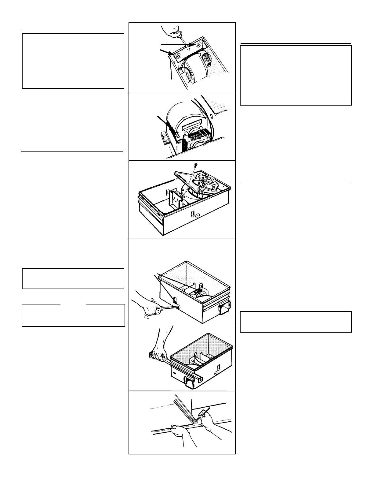
2. Loosen the two retaining screws on the inside
of the heater discharge opening. Place a screwdriver tip between the discharge opening and
the outer housing. Gently pry outward until the
exhaust discharge slips off the support lip on
the outer housing. (FIG. 1)
3. Unhook hinge pins and lift heater assembly out
of housing. (FIG. 2)
4. Unplug the fan assembly from the BLACK receptacle. Remove the plastic bag and set it aside.
5. Remove the mounting screw and carefully lift the
fan assembly out of the housing. (FIG. 3)
6. Refer to the wiring diagram of you unit on the next
page. Remove appropriate knockout(s) by inserting a screwdriver blade into slot(s) and bending it
back and forth to break tabs. (FIG. 4)
7. Insert the adjustable mounting brackets into the
bracket channels on the housing. (FIG. 5)
MODEL HFL695 ONLY
INSTALL THE FAN
8. Choose the location for your fan. For best possible performance, use the shortest possible duct
run and a minimum number of elbows.
9. Position unit between joists and extend mounting
brackets. Position brackets such that bottom edge
of housing will be flush with finished ceiling. Mark
the top of keyhole slot on all four mounting brackets. (FIG. 6)
10. Remove unit temporarily, and pound nails partially
into joists at all four marked locations. (FIG. 7)
11. Hang unit from nails and use embossed measuring guides to check if unit will be flush with finished ceiling. Pound nails tight. For wide joist
centers: A #8 x 3/8 self-tapping screw can be used
to join extended brackets together and create a
rigid mount. To ensure a noise-free mount, crimp
the bracket channels tightly around mounting
brackets. (FIG. 8)
12. Snap the damper/duct connector onto housing.
Make sure that tabs on the connector lock in housing slots. (Top of damper/duct connector will be
flush with top of housing). (FIG. 9)
13. Wire unit using appropriate diagram.
14. Replace heater assembly removed in STEP 3
and plug it into RED receptacle. Direct wires
away from blower inlet.
15. Replace fan assembly removed in STEP 5 and plug
it into BLACK receptacle.
To avoid the possibility of overheating and/or
fire, the grille
FIG. 12. Acorn nut
rod through proper hole in light reflector.
16. Slide the light reflector into opening in grille and
plug into WHITE receptacle. Use acorn nut from
plastic bag to attach grille reflector assembly to
threaded rod on housing. Tighten securely using
pliers or nut driver. Install a light bulb - 100 watt
maximum. (FIG. 10)
17. Install light lens by (1) hooking one of its tabs into
notch in grille/reflector assembly; (2) apply light
pressure to other tab with fingertips and (3) snap
into place. (FIG. 11)
MODEL HFL695 ONLY
CAUTION
must be installed as shown in
must attach to threaded
FIG. 1
RETAINING
SCREWS
TORNILLOS
DE RETEN
FIG. 2
HINGE PIN
PASADORES
DE LA
BISAGRA
FIG. 3
FIG. 4
KNOCKOUTS
DISCOS
REMOVIBLES
FIG. 5
PREPARACION DEL
VENTILADOR
SOLAMENTE PARA EL MODELO HFL695
1. Desconecte el conjunto del calentador del enchufe
ROJO.
2. Afloje los dos tornillos de retén en el interior de la
abertura de salida del calentador. Coloque la punta
del destornillador entre la abertura de salida y la caja
exterior del ventilador. Haga palanca suavemente hacia
afuera hasta que la salida del escape se deslice hacia
afuera del borde de soporte de la caja exterior.
(FIG. 1)
3. Desenganche los pasadores de la bisagra y levante el
conjunto del calentador fuera de la caja. (FIG. 2)
4. Desconecte el conjunto del ventilador del enchufe
NEGRO. Saque la bolsa de plástico y déjela a un lado.
5. Saque el tornillo de montaje y levante con cuidado el
conjunto del ventilador fuera de la caja. (FIG. 3)
6. Refiérase al diagrama de conexiones de la unidad en la
página siguiente. Saque los discos removibles apropiados
introduciendo la punta del destornillador en las ranuras y
moviendo éste de un lado a otro hasta romper las
lengüetas. (FIG. 4)
7. Meta los soportes de montaje ajustables en los canales
para éstos en la caja. (FIG. 5)
INSTALACION DEL
VENTILADOR
8. Elija la posición para su ventilador. Para el mejor
desempeño, use la menor cantidad de ducto y el menor
número posible de codos.
9. Sitúe la unidad entre las vigas y extienda los soportes de
montaje. Coloque los soportes de manera que el extremo
inferior de la caja esté al nivel del cielo raso acabado.
Marque la parte superior de la ranura en las cuatro
soportes de montaje. (FIG. 6)
10. Saque la unidad por unos momentos, y clave los clavos
parcialmente en las vigas en las cuatro posiciones
marcadas. (FIG. 7)
11.Cuelgue la unidad de los clavos y use las guías
estampadas de medición para comprobar si la unidad se
encuentra a nivel con el cielo raso acabado. Termine de
clavar los clavos. En caso de que el centro de las vigas
sea ancho: se puede usar un tornillo autorroscante #8 x
3/8 para juntar los soportes extendidos y crear un soporte
de montaje rígido. Para asegurar un montaje silencioso,
pliegue los canales alrededor de los soportes de montaje.
(FIG. 8)
12. Inserte la conexión del amortiguador/ducto en la caja.
Asegúrese de que las lengüetas del conector se cierran
en las ranuras de la caja.(La parte superior del
amortiguador/ducto debe estar a nivel con la parte
superior de la caja). (FIG. 9)
13. Conecte la unidad de acuerdo con el diagrama apropiado.
SOLO PARA EL MODELO HFL695
14. Vuelva a colocar el conjunto del calentador que se sacó
en el PASO 3 y conéctelo al enchufe ROJO. Instale
los alambres alejados de la entrada de aire al ventilador.
15. Vuelva a colocar el conjunto del ventilador que se sacó
en el paso 5 y conéctelo al enchufe NEGRO.
16. Deslice el reflector de luz en la abertura de la rejilla y
conéctelo al enchufe BLANCO. Use el tornillo para sujetar
la rejilla y el conjunto del reflector al soporte del motor.
Instale una lámpara de un máximo de 100 vatios.
(FIG. 10)
17. Para instalar el lente de la luz: 1)Enganche una de las
lengüetas en la muesca del conjunto rejilla/reflector;
2)Aplique un poco de presión a la otra lengüeta con los
dedos, y 3)Encájela en su sitio. (FIG. 11)
FIG. 6
2
 Loading...