


Broan Ae60 Installation Guide

Installation and User Manual
Address of your installer
06095 rev. A
AE60 / EA 1500 / HV 1.5
RESIDENTIAL USE ONLY
INSTALLER: LEAVE THIS MANUAL WITH THE HOMEOWNER.
HOMEOWNER: USE AND CARE INFORMATION ON PAGES 20 TO 24.
READ AND SAVE THESE INSTRUCTIONS
VB0063

2
!
TO REDUCE THE RISK OF FIRE, ELECTRIC SHOCK, OR INJURY TO PERSON(S)
OBSERVE THE FOLLOWING:
1. This unit is intented for residential installation only.
2. Use this unit only in the manner intended by the manufacturer. If you have questions,
contact the manufacturer at the address or telephone number listed in the warranty.
3. Before replacing filters, servicing or cleaning unit, disconnect power cord from
electrical outlet.
4. Installation must be done in accordance with all applicable codes and standards,
including fire-rated construction codes and standards.
5. This unit is not designed to provide combustion and/or dilution air for fuel-burning
appliances.
6. When cutting or drilling into wall or ceiling, do not damage electrical wiring and other
hidden utilities.
7. Do not use this unit with any solid-state speed control device other than optional wall
controls C34, CMR or ACCGSC3.
8. This unit must be grounded. The power supply cord has a 3-prong grounding plug for
your personal safety. It must be plugged into a mating 3-prong grounding receptacle,
grounded in accordance with the national electrical code and local codes and
ordinances. Do not remove the ground prong. Do not use an extension cord.
9. Do not install in a cooking area or connect directly to any appliances.
10. Do not use to exhaust hazardous or explosive materials and vapors.
11. Do not run any air ducts directly above or closer than 2 ft (0.61 m) to any furnace or
its supply plenum, boiler, or other heat producing appliance. Do not connect the unit
ducts to the furnace ducts, neither return plenum or supply.
12. When performing installation, servicing or cleaning the unit, it is recommended to
wear safety glasses and gloves.
13. When the federal, provincial or state legislation comprises more restrictive installation
and/or certification requirements, the aforementioned requirements prevail on those
of this document and the installer agrees to conform to these at his own expenses.
CAUTION
1. To avoid premature clogged filters, turn OFF the unit during construction or renovation.
2. Please read specification label on product for further information and requirements.
3. Be sure to duct air outside – Do not intake / exhaust air into spaces within walls or
ceiling or into attics, crawl spaces, or garage.
4. Intended for residential installation only in accordance with the requirements of NFPA 90B.
5. The ductwork is intended to be installed in compliance with all local and national
codes that are applicable.
6. Do not use the AE60, EA 1500 or HV 1.5 unit when varnishing. Furthermore, if the
unit is installed in the attic, it is highly recommended to block the stale air intake and
fresh air register. The varnish vapors may damage the unit.
7. At least once in a year, the unit mechanical and electronic parts should be inspected
by qualified service personnel.
8. If the AE60, EA1500 or the HV 1.5 unit is installed in the attic, the unit should not be
turned off during the winter time in order to avoid condensation inside the unit and
inside the ducts.
9. During snow/rain storm, operate the unit in recirculation mode to prevent water build
up in the ventilator.
WARNING

1. YOUR UNIT AND ITS PURPOSE . . . . . . . . . . . . . . . . . . . . . . . . .4
2. TYPICAL INSTALLATIONS . . . . . . . . . . . . . . . . . . . . . . . . . . . . .5
2.1 Basement Installation . . . . . . . . . . . . . . . . . . . . . . . . . . . . . . . . . . . . . . . .5
2.2 Attic Installation . . . . . . . . . . . . . . . . . . . . . . . . . . . . . . . . . . . . . . . . . . . .5
2.3 Mounting Considerations . . . . . . . . . . . . . . . . . . . . . . . . . . . . . . . . . . . . .6
3. INSTALL THE UNIT . . . . . . . . . . . . . . . . . . . . . . . . . . . . . . . . . .7
3.1 Locating and Mounting the Unit . . . . . . . . . . . . . . . . . . . . . . . . . . . . . . . .7
3.2 Tools and Materials . . . . . . . . . . . . . . . . . . . . . . . . . . . . . . . . . . . . . . . . .7
3.3 How to Hang the Unit . . . . . . . . . . . . . . . . . . . . . . . . . . . . . . . . . . . . . . . .7
3.4 Planning of the Ductwork . . . . . . . . . . . . . . . . . . . . . . . . . . . . . . . . . . . . .8
3.5 Installing 6’’ Ducts and Registers . . . . . . . . . . . . . . . . . . . . . . . . . . . .8-10
3.6 Insulated Flexible Ducts Installation . . . . . . . . . . . . . . . . . . . . . . . . . . . .11
3.7 Exterior Opening(s) Installation . . . . . . . . . . . . . . . . . . . . . . . . . . . . .11-17
4. WALL CONTROL . . . . . . . . . . . . . . . . . . . . . . . . . . . . . . . . . .18
4.1 Installation of the Wall Control . . . . . . . . . . . . . . . . . . . . . . . . . . . . .18-20
4.2 Operating the Wall Control . . . . . . . . . . . . . . . . . . . . . . . . . . . . . . . .20-21
5. MAINTENANCE . . . . . . . . . . . . . . . . . . . . . . . . . . . . . . . . . . .22
5.1 Biannual Maintenance . . . . . . . . . . . . . . . . . . . . . . . . . . . . . . . . . . . . . .22
5.2 Annual Maintenance . . . . . . . . . . . . . . . . . . . . . . . . . . . . . . . . . . . . . . . .23
5.3 Master Reset . . . . . . . . . . . . . . . . . . . . . . . . . . . . . . . . . . . . . . . . . . . . .24
6. TROUBLESHOOTING . . . . . . . . . . . . . . . . . . . . . . . . . . . . . . .24
3
TABLE OF CONTENTS
The purpose of this guide is to help you to install properly your unit, and to show you how to
operate and do the maintenance. Please read completely before starting the installation.
Please note the illustrations are typical ones.
We welcome any suggestions you may have concerning this manual and/or the unit, and
we would appreciate hearing your comments on ways to better serve you. Please forward
all correspondence to us at the address indicated on the product registration card included
with this manual.
This manual uses the following symbols to emphasize particular information:
NOTE: Indicates supplementary information needed to fully complete an instruction.
Finally, we want to congratulate you on your purchase of this excellent unit which will
allow you and your family to enjoy fresh air throughout your home for years to come!
NOTE: The unit does not require balancing because of its design.
ABOUT THIS MANUAL/PRODUCT
WARNING
Identifies an instruction which, if not followed, might cause serious
personal injuries including possibility of death.
!
CAUTION
Denotes an instruction which, if not followed, may severely damage the
unit and/or its components.

OPERATIONAL PRINCIPLES
4
1. YOUR UNIT AND ITS PURPOSE
CIRCULATION WITH AIR EXCHANGE:
While continually circulating the air within the house, the unit also evacuates part of this
stale air and replaces it with fresh dry air from the outside. The following extra benefits
are thus obtained: expelling the excess of humidity during the winter months, ventilate the
house on hot summer nights, elimination of stale air.
The air exchanger is designed to eliminate problems of excessive humidity, to steady the
temperature and the humidity and to filter and purify the air inside your house. The air
exchanger carries out the following operations:
AIR RECIRCULATION:
The system recirculates the air inside the house, without exchanging with the outside.
This operation steadies the temperature and the humidity throughout.
FILTRATION:
When the air flows through the system, a mechanical filter traps dust particles.
F
RESH AIR TO
BUILDING
FILTERED AIR
TO BUILDING
STALE AIR TO
OUTSIDE
FRESH AIR
FROM OUTSIDE
STALE AIR
FROM BUILDING
STALE AIR
FROM BUILDING
VF0035
VF0034
5
2. TYPICAL INSTALLATIONS
Only one outside connection is needed when
using the Tandem® transition* and the dual
outside port*, simplifying the installation. These
two components are included in the installation
kit no. 15273 (purchase separately).
NOTES: 1. See Point 2.3
MOUNTING
CONSIDERATIONS
on next page
for required joists opening.
2. The installation kit no. 15273 is not
available in the U.S.A.
*Patented.
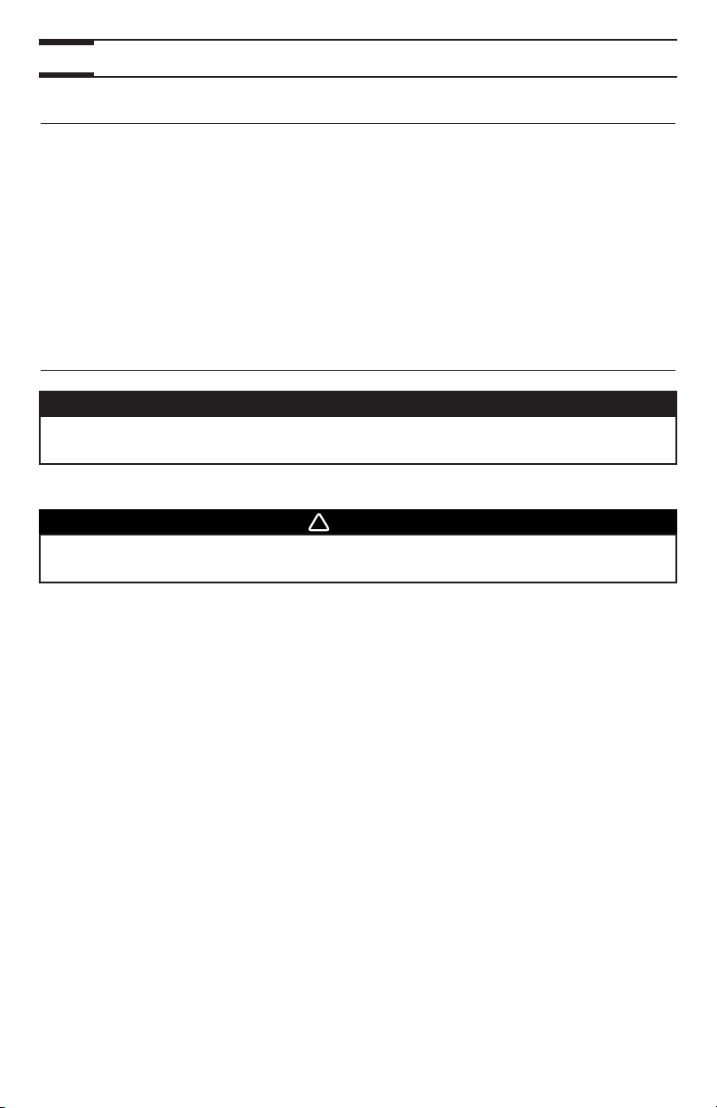
If the unit is installed in the attic, this unit must
always be in operation during the winter season.
Use the installation kit no. EA20130 (purchase
separately).
NOTE: The installation kit no. EA20130 is not
available in the U.S.A.
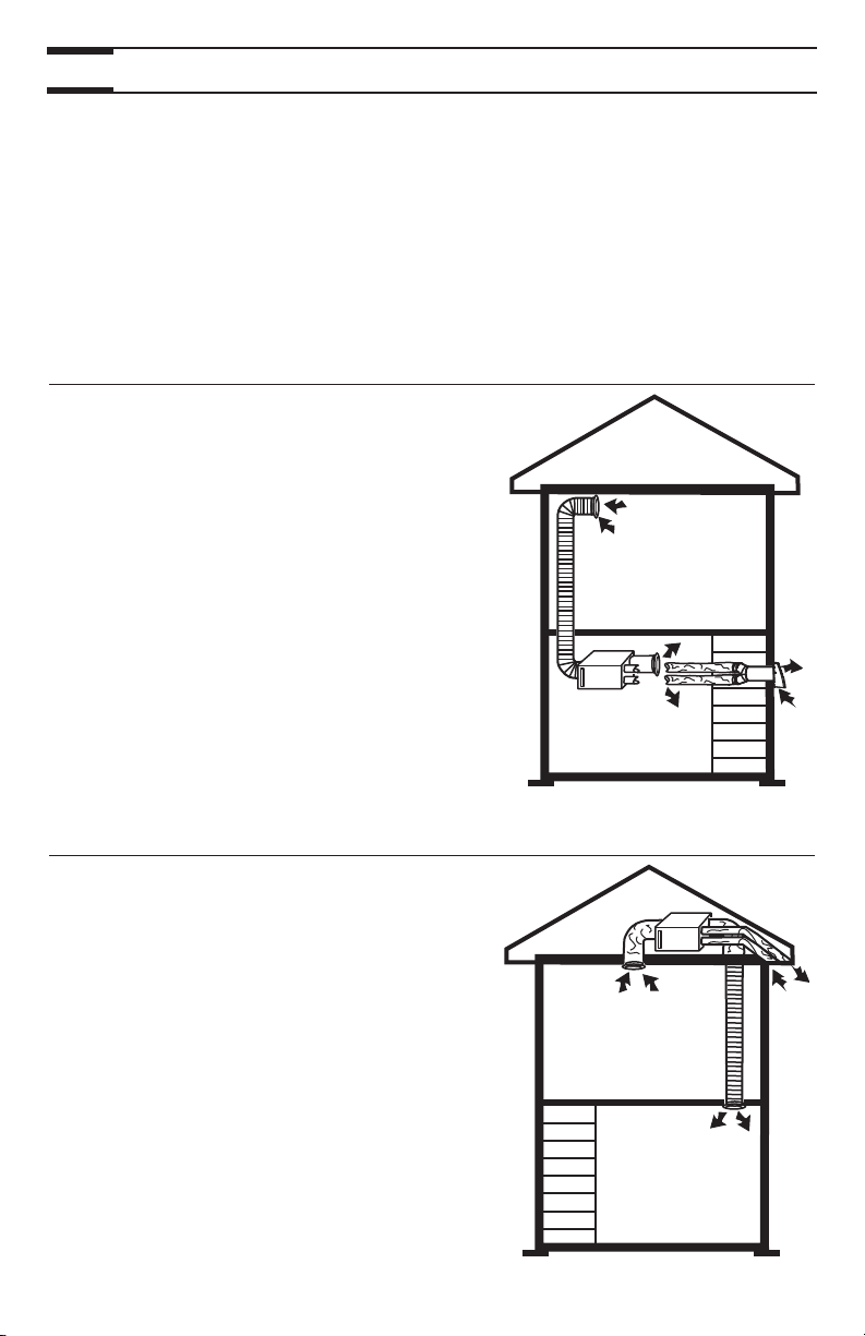
2.1 BASEMENT INSTALLATION
VH0004
2.2 ATTIC INSTALLATION
Use the following illustrations as guidelines to help you decide where your unit will be
installed. The unit should be hung to the joists, using chains and springs (included). If
needed, this unit can be installed upside down. For more details, see Point 3.
INSTALL
THE UNIT
.
In every case, bathroom fan and a range hood should be used to exhaust stale air. Also,
for homes with more than one level, we recommend one exhaust register at the highest
level.
NOTE: An electrical outlet (standard 3-prong grounding outlet) has to be available within
3 feet from the unit.
VH0053

6
2. TYPICAL INSTALLATIONS (CONT’D)
This unit can be used for a retrofit application. Connect the existing ducts to the corresponding
unit ports. If the previous stale air to outside duct and fresh air from outside duct are 5’’
diameter, install the 5’’ diameter adapters (included) over each of the corresponding unit
ports. Also, if using the installation kit no. 15273 or no. EA20130 (not available in the
U.S.A.), install these 5’’ diameter adapters. Use 4 screws (included) per adapter to attach
them to the unit. See figure below.
The joists opening needed to install the Tandem transition must be 9¾’’ (248 mm)
minimum. Also, the maximum heigh of the tandem transition is 8¾’’ (222 mm). See
Tandem transition end view below.
NOTE: The Tandem transition is included in the installation kit no. 15273 (not
available in U.S.A.).
2.3 MOUNTING CONSIDERATIONS
VJ0030
VD0118A
9¾”
248 mm
8¾”
222 mm

7
3. INSTALL THE UNIT
Choose an appropriate location for the unit, far from the areas of the house where peace
and quiet are desired.
• So as to provide easy access for filter maintenance (sometimes, by
installing the unit upside down, it becomes easier to get at the filter).
• Close to an exterior wall, so as to limit the length of the insulated flexible
ducts to and from the unit.
• Away from hot chimneys and other fire hazards.
• Allow for a power source (standard 3-prong grounding outlet).
3.1 LOCATING AND MOUNTING THE UNIT
• Phillips screwdriver no. 2 or Robertson no. 2
• Scissors or utility knife (to cut duct tape and flexible ducts)
• Duct tape
• Jig saw
• A pair of metal shears (if the exterior covering of the house is aluminum
or vinyl)
• A chisel and hammer (if the exterior covering of the house is brick)
• Caulking gun and caulking
3.2 TOOLS AND MATERIALS
Use the 4 chains and springs in the hardware pack provided with the unit. According to
your needs, the unit can be installed upside down.
3.3 HOW TO HANG THE UNIT
CAUTION
Make sure the unit is level.
VD0156
8
3. INSTALL THE UNIT (CONT’D)
• Keep it simple. Plan for a minimum number of bends and joints. Keep the
length of the insulated ducts to a minimum.
• Do not use wall cavities as ducts. Do not use branch lines smaller than
4’’ (102 mm) diameter.
• Do not ventilate crawl spaces or cold room. Do not attempt to recover the
exhaust air from a dryer or a range hood, this would cause the clogging of
the unit.
• Be sure to plan at least one exhaust register on the highest lived-in level of
the house, if it has 2 floors or more.
3.4 PLANNING OF THE DUCTWORK
• Install the stale air exhaust register(s) in the main area where the contaminants
are produced: kitchen, living room, etc. Position the register(s) as far from
the stairway as possible and in such a way that the air circulates in all the
lived-in spaces in the house.
• If a register is installed in the kitchen, it must be located at least 4 feet (1.2 m)
from the range.
• Install the register(s) 6 to 12 inches (152 to 305 mm) from the ceiling on an
interior wall OR install it in the ceiling.
• Attach one end of the 6’’ flexible duct to the stale air exhaust register, and
the other end to the unit stale air from building port, using tie wrap and duct
tape.
3.5 INSTALLING 6’’ DUCTS AND REGISTERS
WARNING
Never install a stale air exhaust register in a room where a combustion
device operates, such as a gas water heater, a gas furnace or a fireplace.
!
3.5.1 STALE AIR EXHAUST DUCTWORK
• Install the fresh air distribution register(s) in a large, open area in the lowest
level to ensure the greatest possible air circulation. Keep in mind that the fresh
air register(s) must be located as far as possible from the stale air register(s).
• Install the register(s) in the ceiling OR 6 to 12 inches (152 to 305 mm) from
the ceiling on an interior wall. The duct length should be at least 15’ (4.6 m).
(The cooler air will then cross the upper part of the room and mix with room
air before descending to occupant level.)
• Attach one end of the 6’’ flexible duct to the fresh air distribution register,
and the other end to the unit fresh air to building port, using tie wrap and
duct tape.
3.5.2 FRESH AIR DISTRIBUTION DUCTWORK
CAUTION
If ducts have to go through an unconditioned space, always use insulated
ducts (purchase separately).
 Loading...