

MODELS 170F, 174F & 178F
FAN FORCED WALL HEATERS
FINISH ASSEMBLIES
FOR USE WITH BROAN MODEL 171H ROUGH-IN HOUSING
READ AND SAVE THESE INSTRUCTIONS
WARNING
1. ALL ELECTRICAL WORK MUST BE DONE IN ACCORDANCE WITH LOCAL OR NATIONAL ELECTRICAL CODE
AS APPLICABLE. FOR SAFETY, THIS PRODUCT MUST
BE GROUNDED. IF YOU ARE UNFAMILIAR WITH METHODS OF INSTALLING ELECTRICAL WIRING, SECURE
THE SERVICES OF A QUALIFIED ELECTRICIAN.
2. WHEN WIRING, SERVICING OR CLEANING THIS UNIT,
TURN OFF POWER AND LOCK OUT SERVICE PANEL.
FAILURE TO DO SO COULD ALLOW OTHERS OR THERMOSTAT TO TURN ON POWER UNEXPECTEDLY WHICH
MAY CAUSE FATAL ELECTRICAL SHOCK.
3. To avoid electrical shock:
• DO NOT install unit in a tub or shower enclosure or any
location where it may come in contact with water.
• NEVER place a switch where it can be reached from a
tub or shower.
4. DO NOT install this unit in an area where chemicals or
other flammables are stored or used. Explosion and fire
may result
.
PLAN THE INSTALLATION
This wall heater finish assembly is intended for installation
into a Broan Model 171H rough-in housing — after the wall
has been completed.
The heater can be operated using the Broan Model 86 LineVoltage Thermostat from a wall location or the Broan Model
83 Integral Thermostat installed into heater. Purchase the control separately.
CAUTION
1. This product may ONLY be installed horizontally in a wall.
DO NOT MOUNT IN ANY OTHER POSITION.
2. Install heater at least 6” from floor or any adjacent vertical
surface.
3. DO NOT locate heater behind a door, furniture, drapes,
etc., where the air flow to the unit would be restricted.
4. Provide heater with an appropriately-rated electrical circuit to prevent tripped breakers or blown fuses. (See chart
below).
5. DO NOT CONNECT HEATER TO DIMMER SWITCH OR
SPEED CONTROL.
6. To avoid motor bearing damage and noisy and/or unbalanced impellers, keep drywall spray, construction dust,
etc., off power unit.
7. Please read specification label on product for further information and requirements.
Follow these basic steps when installing this heater:
• Remove the housing mask.
• Fasten finish assembly inside housing.
• Plug assembly in.
• Attach grille.
!
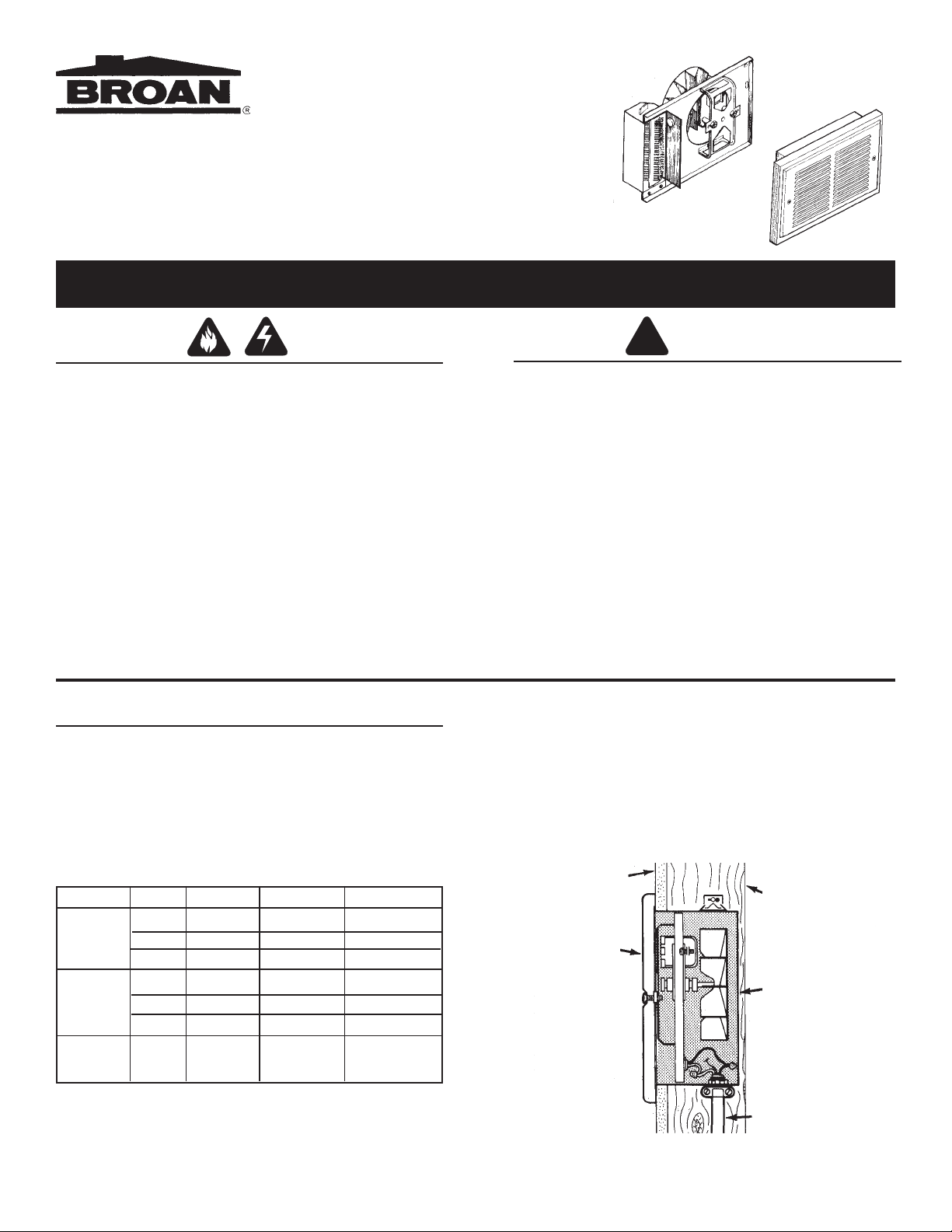
The table below lists the ratings for each model.
MODELS VOLTS AMPS WATTS BTU/HR
120 8.33/4.16 1000/500 3413/1707
170F 240 4.16 1000 3413
208 3.61 750 2560
120 12.5/6.25 1500/750 5120/2560
174F 240 6.25 1500 5120
208 5.41 1125 3640
178F 240 8.33/4.16 2000/1000 6827/3413
208 7.21/3.61 1500/750 5120/2560
BOLD ratings are factory wired. See "OPTIONAL WIRING
CONVERSIONS" section on pages 2 and 3 for wattage and
voltage conversion instructions.
DRYWALL
GRILLE
WALL
STUD
HEATER
HOUSING
POWER
CABLE
INSTALL THE HEATER ASSEMBLY OPTIONAL WIRING CONVERSIONS
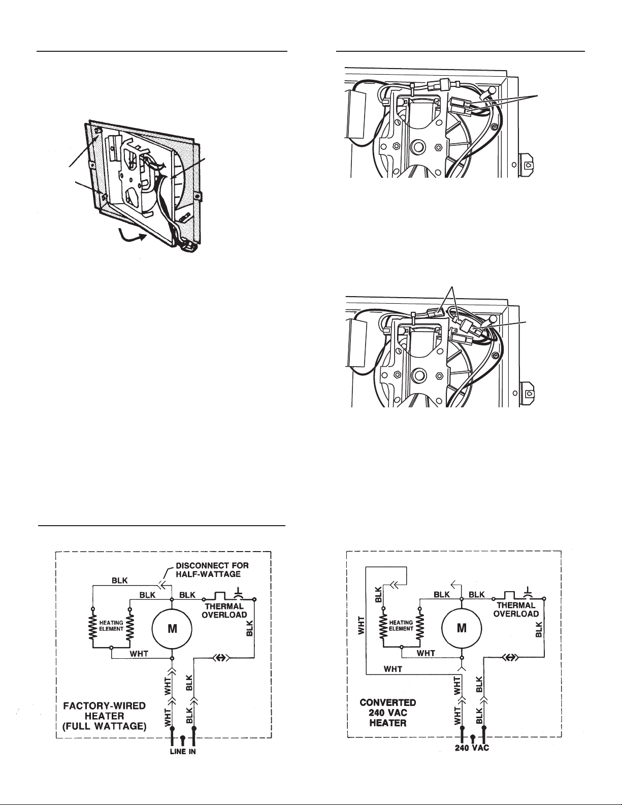
1. Remove housing mask.
Make sure wall has been finished (including paint or wall
paper, etc.) Take out and discard the cardboard mask from
inside of housing.
FASTEN TO
HOUSING WITH
TABS
RETAINING SCREW -
HERE
1. Conversion to half-wattage.
The heater will produce less heat and use less electricity if
converted to half-wattage.
Disconnect ONE of the black wires with an insulated terminal from the motor.
BLACK
WIRES
(connected
to motor)
2. Install heater assembly into housing.
Place element end of heater assembly behind the tabs on
the left side of housing. Pivot the assembly in and fasten
with retaining screw from parts bag.
Plug wiring harness into receptacle.
3. Provide desired control.
The heater finish assembly has no adjustable thermostat
control.
If a wall-mounted control has been pre-wired, nothing else
need be done.
If a built-in thermostat is desired, purchase and insert the
Broan Model 83 Integral Thermostat at this time.
WIRING DIAGRAM
WHITE WIRES
BLACK WIRE
(from motor)
2. 120 VAC to 240 VAC Conversion.
(Factory-wired 120 VAC Models 170F and 174F ONLY)
1) Disconnect ONE of the black wires with an insulated
terminal from the motor.
2) Disconnect the two (2) white wires with insulated
terminals from each other. Do not remove wire from
beneath plastic wire tie.
3) Connect black wire to white wire.
NOTE: When heater is converted from 120 VAC to 240 VAC,
half-wattage conversion is not possible
2

COMPLETE THE INSTALLATION
USE AND CARE
1. Attach grille.
Fasten grille to heater with two (2) screws from parts bag.
2. Check operation.
Turn on power at service entrance. Turn thermostat to its
highest setting and make sure heating element and blower
come on. Then turn it to its lowest setting and make sure
element and blower shut off.
DISCONNECT ELECTRIC POWER AT SERVICE
WARNING
ENTRANCE BEFORE CLEANING OR SERVICING UNIT.
THERMAL OVERLOAD PROTECTOR
If heater fails to operate when thermostat is turned to its highest setting: Turn power off at service entrance. Remove grille
and press button marked "RESET".
CLEANING
Clean the heater using the round brush tool on your vacuum
cleaner. Remove large accumulations of dust, lint, etc., that
might impede the flow of air through the heater. Such blockage will lower its efficiency and create a possible over-heating condition.
To clean grille, use a soft cloth which has been moistened with
household window cleaner.
CAUTION: METAL AND ELECTRICAL PARTS SHOULD
NEVER BE IMMERSED IN WATER.
Broan-NuTone LLC warrants to the original consumer purchaser of its products that such products will be free from defects in materials
or workmanship for a period of one year from the date of original purchase. THERE ARE NO OTHER WARRANTIES, EXPRESS OR
IMPLIED, INCLUDING, BUT NOT LIMITED TO, IMPLIED WARRANTIES OF MERCHANTABILITY OR FITNESS FOR A PARTICULAR
PURPOSE.
During this one-year period, Broan-NuTone LLC will, at its option, repair or replace, without charge, any product or part which is found
to be defective under normal use and service.
THIS WARRANTY DOES NOT EXTEND TO FLUORESCENT LAMP STARTERS AND TUBES. This warranty does not cover (a) normal
maintenance and service or (b) any products or parts which have been subject to misuse, negligence, accident, improper maintenance
or repair (other than by Broan-NuTone LLC), faulty installation or installation contrary to recommended installation instructions.
The duration of any implied warranty is limited to the one-year period as specified for the express warranty. Some states do not allow
limitation on how long an implied warranty lasts, so the above limitation may not apply to you.
BROAN-NUTONE LLC’S OBLIGATION TO REPAIR OR REPLACE, AT BROAN-NUTONE LLC’S OPTION, SHALL BE THE PURCHASER’S
SOLE AND EXCLUSIVE REMEDY UNDER THIS WARRANTY. BROAN-NUTONE LLC SHALL NOT BE LIABLE FOR INCIDENTAL,
CONSEQUENTIAL OR SPECIAL DAMAGES ARISING OUT OF OR IN CONNECTION WITH PRODUCT USE OR PERFORMANCE.
Some states do not allow the exclusion or limitation of incidental or consequential damages, so the above limitation or exclusion may
not apply to you.
This warranty gives you specific legal rights, and you may also have other rights, which vary from state to state. This warranty supersedes
all prior warranties.
To qualify for warranty service, you must (a) notify Broan-NuTone LLC at the address or telephone number below, (b) give the model
number and part identification and (c) describe the nature of any defect in the product or part. At the time of requesting warranty service,
you must present evidence of the original purchase date.
Broan-NuTone LLC One Year Limited Warranty
Broan-NuTone LLC, 926 West State Street, Hartford, WI 53027 (1-800-637-1453)
3
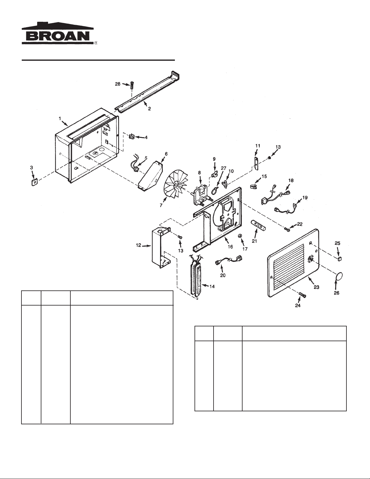
SERVICE PARTS
FAN-FORCED
WALL HEATER
KEY PART
NO. NUMBER DESCRIPTION
1 97008681 Housing
2 98003036 Mounting Bracket (2 Required)
3 99260512 #8-18 Sheet Metal Nut (2 Required)
4 99390015 Grounding Clip
5 97005422 Receptacle Assembly
6 98006975 Wiring Cover
7 99020130 Blower Wheel
8 99080248 Motor (Models 170F and 174F)
99080252 Motor (Model 178F)
9 99270735 Tab Adapter
10 99030194 Thermal Overload
11 99271091 Guard
12 98006974 Element Bracket
13 99150491 Screw, #8-18 x 3/8 Ph. Pan Head
(5 Required)
14 99270741 Heating Element (Model 170F)
99270725 Heating Element (Model 174F)
99270742 Heating Element (Model 178F)
15 93270619 Wire Clamp
16 97008682 Partition Plate Assembly
Always order replacement parts by part number - NOT key number.
KEY PART
NO. NUMBER DESCRIPTION
17 99260428 Nut, #6-32 x 5/16 Keps (2 Required)
18 97008675 Plug Assembly
19 97008677 Thermostat Wire Assembly
20 97008678 Overload Wire Assembly
21 99270743 Terminal Jumper
22 99150533 Screw, #8-18 x 5/8 Ph. Pan Head
23 98006970 Grille
24 99150528 Grille Screw (2 Required)
25 99090681 Grille Logo
26 99090688 Cover Label
27 93270493 Wire Tie
28 99150470 Screw, #8-18 x 3/8 Ph. Truss Hd.
Broan-NuTone LLC, 926 West State Street, Hartford, WI 53027
99041235H
 Loading...