


Worcester 2000
Bosch Worcester 2000, Worcester GC2000iW C, Worcester GC2000iW 30 C NG, Worcester GC2000iW 25 C NG Installation And Maintenance Instructions Manual

Installation and Maintenance Instructions
Gas-fired condensing combi appliance
Worcester 2000
GC2000iW C
6 721 814 551 (2019/09) UK/IE
2
3
1
40
bar
Table of contents
Table of contents
1 Explanation of symbols and safety instructions . . . . . . . . . . . 3
1.1 Explanation of symbols . . . . . . . . . . . . . . . . . . . . . . . . . . 3
1.2 General safety instructions . . . . . . . . . . . . . . . . . . . . . . . 4
2 Regulations . . . . . . . . . . . . . . . . . . . . . . . . . . . . . . . . . . . . . . . . . . 6
3 Product Information . . . . . . . . . . . . . . . . . . . . . . . . . . . . . . . . . . 7
3.1 Misuse. . . . . . . . . . . . . . . . . . . . . . . . . . . . . . . . . . . . . . . . 7
3.2 Scope of delivery . . . . . . . . . . . . . . . . . . . . . . . . . . . . . . . 7
3.3 Declaration of Conformity . . . . . . . . . . . . . . . . . . . . . . . . 7
3.4 Appliance type overview . . . . . . . . . . . . . . . . . . . . . . . . . 7
3.5 Product identification . . . . . . . . . . . . . . . . . . . . . . . . . . . 8
3.6 Pipe work positions and flue outlet. . . . . . . . . . . . . . . . . 8
3.7 Product overview . . . . . . . . . . . . . . . . . . . . . . . . . . . . . . . 9
3.8 Product data for energy consumption. . . . . . . . . . . . . . 10
3.9 Standard accessories. . . . . . . . . . . . . . . . . . . . . . . . . . . 10
3.9.1 Appliance accessories . . . . . . . . . . . . . . . . . . . . . . . . . . 10
3.9.2 Programmer/timer accessories. . . . . . . . . . . . . . . . . . . 10
4 Pre-Installation. . . . . . . . . . . . . . . . . . . . . . . . . . . . . . . . . . . . . . 11
4.1 System preparation . . . . . . . . . . . . . . . . . . . . . . . . . . . . 11
4.1.1 Artificially softened water . . . . . . . . . . . . . . . . . . . . . . . 11
4.1.2 Water systems and pipe work . . . . . . . . . . . . . . . . . . . . 11
4.1.3 System layouts examples. . . . . . . . . . . . . . . . . . . . . . . . 12
4.1.4 System fill . . . . . . . . . . . . . . . . . . . . . . . . . . . . . . . . . . . . 12
4.2 Mains supply. . . . . . . . . . . . . . . . . . . . . . . . . . . . . . . . . . 13
4.2.1 Electrical supply . . . . . . . . . . . . . . . . . . . . . . . . . . . . . . . 13
4.2.2 Gas supply . . . . . . . . . . . . . . . . . . . . . . . . . . . . . . . . . . . 13
4.2.3 Water supply. . . . . . . . . . . . . . . . . . . . . . . . . . . . . . . . . . 13
4.3 Appliance location and clearances . . . . . . . . . . . . . . . . 14
4.3.1 Appliance location . . . . . . . . . . . . . . . . . . . . . . . . . . . . . 14
4.3.2 Rooms containing a bath or shower . . . . . . . . . . . . . . . 15
4.3.3 Appliance clearances. . . . . . . . . . . . . . . . . . . . . . . . . . . 15
4.4 Flue systems considerations . . . . . . . . . . . . . . . . . . . . . 16
4.4.1 Flue length . . . . . . . . . . . . . . . . . . . . . . . . . . . . . . . . . . . 16
4.4.2 Flue options . . . . . . . . . . . . . . . . . . . . . . . . . . . . . . . . . . 16
4.4.3 Plume management system. . . . . . . . . . . . . . . . . . . . . . 18
4.4.4 Flue terminal positions . . . . . . . . . . . . . . . . . . . . . . . . . 18
4.4.5 Plume re-direct and plume management terminal
positions . . . . . . . . . . . . . . . . . . . . . . . . . . . . . . . . . . . . . 22
4.5 Condensate discharge . . . . . . . . . . . . . . . . . . . . . . . . . . 24
4.5.1 Condensate pipe work. . . . . . . . . . . . . . . . . . . . . . . . . . 24
4.5.2 Condensate production . . . . . . . . . . . . . . . . . . . . . . . . . 24
4.5.3 Internal connections . . . . . . . . . . . . . . . . . . . . . . . . . . . 24
4.5.4 External connections . . . . . . . . . . . . . . . . . . . . . . . . . . . 25
4.6 Pressure relief discharge. . . . . . . . . . . . . . . . . . . . . . . . 28
4.6.1 Pressure relief pipe work. . . . . . . . . . . . . . . . . . . . . . . . 28
4.6.2 Alternative PRV connections - Combined PRV/
condensate. . . . . . . . . . . . . . . . . . . . . . . . . . . . . . . . . . . 28
4.7 Cleaning primary systems . . . . . . . . . . . . . . . . . . . . . . . 29
4.7.1 Flushing the system . . . . . . . . . . . . . . . . . . . . . . . . . . . . 29
5 Installation . . . . . . . . . . . . . . . . . . . . . . . . . . . . . . . . . . . . . . . . . 30
5.1 Position the appliance . . . . . . . . . . . . . . . . . . . . . . . . . . 30
5.1.1 Mounting bracket fixing . . . . . . . . . . . . . . . . . . . . . . . . . 30
5.2 Appliance connections . . . . . . . . . . . . . . . . . . . . . . . . . 31
5.3 Hanging the appliance . . . . . . . . . . . . . . . . . . . . . . . . . . 32
5.4 Flue turret/adaptor installation. . . . . . . . . . . . . . . . . . . 33
5.5 Electrical connection . . . . . . . . . . . . . . . . . . . . . . . . . . . 34
5.5.1 Installer connections . . . . . . . . . . . . . . . . . . . . . . . . . . . 35
5.5.2 Cable preparations . . . . . . . . . . . . . . . . . . . . . . . . . . . . 35
5.5.3 Key (accessories). . . . . . . . . . . . . . . . . . . . . . . . . . . . . . 36
6 Commissioning. . . . . . . . . . . . . . . . . . . . . . . . . . . . . . . . . . . . . . 36
6.1 Pre-Commissioning checks . . . . . . . . . . . . . . . . . . . . . . 36
6.2 Water treatment. . . . . . . . . . . . . . . . . . . . . . . . . . . . . . . 37
6.2.1 Filling the appliance and adding Inhibitor. . . . . . . . . . . 37
6.3 Circulation pump . . . . . . . . . . . . . . . . . . . . . . . . . . . . . . 38
6.4 Starting the appliance . . . . . . . . . . . . . . . . . . . . . . . . . . 38
6.4.1 Control panel overview . . . . . . . . . . . . . . . . . . . . . . . . . 38
6.4.2 Screen display . . . . . . . . . . . . . . . . . . . . . . . . . . . . . . . . 39
6.4.3 Switching on the device. . . . . . . . . . . . . . . . . . . . . . . . . 39
6.4.4 Setting the flow temperature. . . . . . . . . . . . . . . . . . . . . 39
6.4.5 Setting the DHW heating . . . . . . . . . . . . . . . . . . . . . . . . 39
6.4.6 Setting the heating control device . . . . . . . . . . . . . . . . 40
6.4.7 After commissioning . . . . . . . . . . . . . . . . . . . . . . . . . . . 40
6.4.8 Setting summer mode . . . . . . . . . . . . . . . . . . . . . . . . . . 40
6.5 Chimney sweep mode . . . . . . . . . . . . . . . . . . . . . . . . . . 40
6.5.1 Setting the appliance to maximum . . . . . . . . . . . . . . . . 40
6.5.2 Setting the appliance to minimum . . . . . . . . . . . . . . . . 40
6.5.3 Exiting chimney sweep mode . . . . . . . . . . . . . . . . . . . . 40
6.6 Checking gas inlet pressure. . . . . . . . . . . . . . . . . . . . . . 40
6.7 Checking the gas rate. . . . . . . . . . . . . . . . . . . . . . . . . . . 41
6.8 Checking for gas leaks during operation. . . . . . . . . . . . 41
6.9 CO and combustion check. . . . . . . . . . . . . . . . . . . . . . . 42
6.10 Checking flue integrity. . . . . . . . . . . . . . . . . . . . . . . . . . 43
6.11 Flue gas analysis. . . . . . . . . . . . . . . . . . . . . . . . . . . . . . . 43
6.12 Finishing commissioning . . . . . . . . . . . . . . . . . . . . . . . . 44
6.12.1 Fitting the front panel . . . . . . . . . . . . . . . . . . . . . . . . . . 44
6.12.2 Appliance/product guarantee . . . . . . . . . . . . . . . . . . . . 44
7 Shutdown . . . . . . . . . . . . . . . . . . . . . . . . . . . . . . . . . . . . . . . . . . 45
7.1 Setting frost protection . . . . . . . . . . . . . . . . . . . . . . . . . 45
7.2 Anti-seize protection . . . . . . . . . . . . . . . . . . . . . . . . . . . 45
8 Settings in the service menu . . . . . . . . . . . . . . . . . . . . . . . . . . 45
8.1 Operating the service menu . . . . . . . . . . . . . . . . . . . . . 45
8.2 Service functions overview . . . . . . . . . . . . . . . . . . . . . . 46
8.2.1 Menu 1 . . . . . . . . . . . . . . . . . . . . . . . . . . . . . . . . . . . . . . 46
8.2.2 Menu 2 . . . . . . . . . . . . . . . . . . . . . . . . . . . . . . . . . . . . . . 46
8.2.3 Menu 3 . . . . . . . . . . . . . . . . . . . . . . . . . . . . . . . . . . . . . . 47
8.2.4 Menu 4 . . . . . . . . . . . . . . . . . . . . . . . . . . . . . . . . . . . . . . 48
8.2.5 Menu 5 . . . . . . . . . . . . . . . . . . . . . . . . . . . . . . . . . . . . . . 49
8.2.6 Menu 6 . . . . . . . . . . . . . . . . . . . . . . . . . . . . . . . . . . . . . . 50
8.2.7 Menu 0 . . . . . . . . . . . . . . . . . . . . . . . . . . . . . . . . . . . . . . 50
9 Inspection and maintenance . . . . . . . . . . . . . . . . . . . . . . . . . . 51
9.1 Inspection and maintenance considerations . . . . . . . . 51
9.2 Service functions . . . . . . . . . . . . . . . . . . . . . . . . . . . . . . 51
9.2.1 Calling up the last fault saved . . . . . . . . . . . . . . . . . . . . 51
9.3 Component access . . . . . . . . . . . . . . . . . . . . . . . . . . . . 51
9.4 Fan pressure test . . . . . . . . . . . . . . . . . . . . . . . . . . . . . . 52
9.4.1 Checking heating block . . . . . . . . . . . . . . . . . . . . . . . . . 52
9.5 Check working gas inlet pressure . . . . . . . . . . . . . . . . . 52
2
Worcester 2000 – 6 721 814 551 (2019/09)
Table of contents
9.6 Flue gas analysis . . . . . . . . . . . . . . . . . . . . . . . . . . . . . . .52
9.7 Checking the flue integrity . . . . . . . . . . . . . . . . . . . . . . . 53
9.8 Cleaning the siphon and heat exchanger . . . . . . . . . . .53
9.8.1 Cleaning the heat exchanger . . . . . . . . . . . . . . . . . . . . .53
9.8.2 Cleaning the siphon . . . . . . . . . . . . . . . . . . . . . . . . . . . .56
9.9 Setting the air/gas ratio . . . . . . . . . . . . . . . . . . . . . . . . .58
10 Replacement parts . . . . . . . . . . . . . . . . . . . . . . . . . . . . . . . . . . .58
10.1 Component access. . . . . . . . . . . . . . . . . . . . . . . . . . . . .59
10.2 Draining the appliance . . . . . . . . . . . . . . . . . . . . . . . . . .59
10.3 Checking the strainer in the cold water pipe. . . . . . . . .59
10.4 Checking the plate heat exchanger . . . . . . . . . . . . . . . .60
10.5 Checking the expansion vessel . . . . . . . . . . . . . . . . . . .60
10.6 Adjusting the operating pressure of the heating
system. . . . . . . . . . . . . . . . . . . . . . . . . . . . . . . . . . . . . . .60
10.7 Removing the gas valve . . . . . . . . . . . . . . . . . . . . . . . . .60
10.8 Removing the pump . . . . . . . . . . . . . . . . . . . . . . . . . . . .61
10.9 Removing the automatic air vent valve . . . . . . . . . . . . .61
10.10 Removing the motor of the diverter valve . . . . . . . . . . .61
10.11 Removing the heat exchanger . . . . . . . . . . . . . . . . . . . . 62
10.12 Replacing the control unit . . . . . . . . . . . . . . . . . . . . . . .62
10.13 Reattaching the casing on the side . . . . . . . . . . . . . . . .63
11 Fault finding and diagnosis . . . . . . . . . . . . . . . . . . . . . . . . . . . .63
11.1 General information . . . . . . . . . . . . . . . . . . . . . . . . . . . .63
11.2 Table of operation and fault displays. . . . . . . . . . . . . . .64
11.3 Pump operation and diagnosis . . . . . . . . . . . . . . . . . . .71
11.4 Faults that are not displayed . . . . . . . . . . . . . . . . . . . . . 72
12 Environmental protection/disposal. . . . . . . . . . . . . . . . . . . . .73
13 Technical Specifications/Logs . . . . . . . . . . . . . . . . . . . . . . . . .74
13.1 Technical data . . . . . . . . . . . . . . . . . . . . . . . . . . . . . . . . .74
13.2 Component resistance characteristics . . . . . . . . . . . . .75
13.2.1 Sensor values . . . . . . . . . . . . . . . . . . . . . . . . . . . . . . . . .75
13.3 Heating curve . . . . . . . . . . . . . . . . . . . . . . . . . . . . . . . . .75
13.4 Internal wiring of the appliance . . . . . . . . . . . . . . . . . . .76
13.4.1 Electircal wiring . . . . . . . . . . . . . . . . . . . . . . . . . . . . . . .76
13.5 Setting values for output . . . . . . . . . . . . . . . . . . . . . . . .77
13.5.1 Gas setting values. . . . . . . . . . . . . . . . . . . . . . . . . . . . . .77
13.6 Gas Boiler System Commissioning Checklist and
Warranty Validation Record . . . . . . . . . . . . . . . . . . . . . .78
13.7 Inspection and maintenance checklist . . . . . . . . . . . . .79
13.8 Service and Interim Boiler Work Record . . . . . . . . . . . .80
1 Explanation of symbols and safety instructions
1.1 Explanation of symbols
Warnings
In warnings, signal words at the beginning of a warning are used to
indicate the type and seriousness of the ensuing risk if measures for
minimising danger are not taken.
The following signal words are defined and can be used in this document:
DANGER:
DANGER indicates that severe or life-threatening personal injury will
occur.
WARNING:
WARNING indicates that severe to life-threatening personal injury may
occur.
CAUTION:
CAUTION indicates that minor to medium personal injury may occur.
NOTICE:
NOTICE indicates that material damage may occur.
Important information
The info symbol indicates important information where there is no risk to
people or property.
Additional symbols
Symbol Meaning
▶ a step in an action sequence
a reference to a related part in the document
• a list entry
– a list entry (second level)
Table 1
Worcester 2000 – 6 721 814 551 (2019/09)
3

Explanation of symbols and safety instructions
1.2 General safety instructions
H Please read these instructions carefully before
starting installation.
• These instructions are applicable to the Worcester
appliance model(s) stated on the front cover of this
manual only and must not be used with any other
make or model of appliance.
• These instructions apply in the UK and Ireland only
and must be followed except for any statutory
obligations.
• This appliance must be installed by a competent
registered gas engineer, such as a Gas Safe
registered engineer including a British Gas
engineer. Failure to install correctly could lead to
prosecution.
• If you are in any doubt, contact the Worcester,
Bosch Group help line
(0330 123 3366).
• Distance learning and training courses are available
from Worcester.
• The BENCHMARK Commissioning Checklist can be
found on page 78 of this Installation manual.
H Notices for the target group
These installation instructions are intended for gas,
plumbing, heating and electrical contractors. All
instructions must be observed. Failure to comply with
instructions may result in material damage and
personal injury, including danger to life.
▶ Read the installation instructions (heat source,
heating controller, etc.) before installation.
▶ Observe the safety instructions and warnings.
▶ Follow national and regional regulations, technical
regulations and guidelines.
▶ Record all work carried out.
H Intended use
The appliance may only be used for heating water or
domestic hot water in domestic properties.
▶ Observe the details on the data plate and the
specifications (installation manual) to ensure
correct use of this appliance.
▶ Worcester Bosch offer flue gas systems which are
suitable for use with the appliance. It is the
responsibility of the designer/installer of the flue to
ensure this flue gas system operates correctly and
in a safe manner.
H If you smell gas
A gas leak could potentially cause an explosion. If you
smell gas, observe the following rules:
▶ Prevent flames or sparks:
– Do not smoke, use a lighter or strike matches.
– Do not operate any electrical switches or unplug
any equipment.
– Do not use the telephone or ring doorbells.
▶ Turn off the gas at the meter or regulator.
▶ Open windows and doors.
▶ Warn your neighbours and leave the building.
▶ Prevent anyone from entering the building.
▶ Move well away from the building: call the National
Gas Emergency Service on 0800 111 999.
▶ L.P.G. boilers: Call the supplier’s number on the
side of the gas tank.
H Risk to life from carbon monoxide poisoning
There is a risk to life from escaping flue gases
▶ Do not modify the flue gas system.
▶ Ensure that flue pipes and gaskets are undamaged.
If flue pipes are damaged or leaking:
▶ Turn off and isolate the appliance.
▶ Open windows and doors.
▶ If necessary, leave the building and warn your
neighbours.
▶ Prevent anyone from entering the building.
▶ Rectify any damage to the flue system immediately.
H Installation and maintenance
Installation and maintenance must only be carried out
by a competent registered gas engineer, such as Gas
Safe registered engineer or British Gas engineer.
▶ Carry out a gas tightness test after completing work
on gas-carrying components.
▶ Only use original spares.
H Electrical work
Electrical work must only be carried out by a qualified
electrician:
▶ Before starting electrical work;
– Ensure that the electricity supply is safely
Isolated and secured to prevent inadvertent reconnection.
Information on safe isolation can be found in the
Health and Safety Executive guidance HSG85.
– Using test equipment approved to GS38 to
confirm that the electricity supply is
disconnected.
▶ Refer to the manufacturer’s information when
installing non Worcester components and systems
to the Worcester appliance.
4
Worcester 2000 – 6 721 814 551 (2019/09)

Explanation of symbols and safety instructions
H Handover to the user
When handing over, instruct the user how to operate
the heating system and inform the user about its
operating conditions.
▶ Explain how to operate the heating system and draw
the user's attention to any safety relevant action.
▶ Explain that modifications and repairs must only be
performed by a competent, registered gas
engineer, such as a Gas Safe registered engineer or
British Gas engineer.
▶ Leave the installation instructions with the
completed Benchmark Checklist (or a certificate
confirming compliance with IS 813, Eire only) and
the operating instructions with the user or at the gas
meter.
H Servicing
Advise the user to have the system serviced annually
by a competent, registered gas engineer, such as a Gas
Safe registered engineer or British Gas engineer.
Approved spares must be used to help maintain the
efficiency, safety and reliability of the appliance.
H Benchmark Service Record
The service engineer must complete the Benchmark
Service Record at the back of this manual after each
service.
Benchmark places
responsibilities on both
manufacturers and
installers.
The purpose is to ensure that customers are provided
with the correct equipment for their needs, that it is
installed, commissioned and serviced in accordance
with the manufacturer's instructions by competent
persons and that it meets the requirements of the
appropriate Building Regulations. The Benchmark
Checklist can be used to demonstrate compliance
with Building Regulations and should be provided to
the customer for future reference.
Installers are required to carry out installation,
commissioning and servicing work in accordance with
the Benchmark Code of Practice which is available
from the Heating and Hot water Industry Council who
manage and promote the scheme.
Visit hhic.org.uk for more information.
H Combustion and corrosive materials
Do not store or use any combustible materials (paper,
thinners, paints etc.) inside or within the vicinity of the
appliance.
Chemically aggressive substances can corrode the
appliance and invalidate any warranty.
H Fitting and modification
Fitting the appliance and any controls to the appliance
may only be carried out by a competent engineer in
accordance with the current Gas Safety (Installation
and Use) Regulations.
Flue systems must not be modified in any way other
than as described in the fitting instructions. Any
misuse or unauthorised modifications to the
appliance, flue or associated components and
systems could invalidate the warranty. The
manufacturer accepts no liability arising from any such
actions, excluding statutory rights.
H General manual handling guidelines
▶ Only remove packaging at the time of the final
installation.
▶ Always use Health and Safety guidance for manual
handling of an appliance.
– Never lift or carry more than the safe guidance
limit on your own.
– Always use appropriate methods and equipment
when lifting/carrying an appliance.
▶ Never lift or carry packages by the shipping straps.
▶ During handling and unpacking, wear safety gloves
to prevent injuries to your hands through sharpedged appliance components.
▶ Dispose of packing materials appropriately.
H Important handling instructions
Care should be taken when transporting, lifting and
carrying the appliance.
▶ Use a means of transport suitable for handling
appliances (e.g. sack truck with strap, stair
climbing or step trolley).
▶ When handling appliances, secure them against a
fall.
▶ Let only trained personnel undertake the handling.
▶ The correct method for handling heavy objects
should be strictly observed, at all times.
H Health and safety
The appliance contains no asbestos and no
substances have been used in the construction
process that contravene the COSHH Regulations
(Control of Substances Hazardous to Health
Regulations 1988).
Worcester 2000 – 6 721 814 551 (2019/09)
5

Regulations
2 Regulations
Installation regulations
Current Gas Safety (Installation and Use) Regulations:
All gas appliances must be installed by a competent, registered gas
engineer, such as a Gas Safe registered engineer or British Gas engineer
in accordance with the current regulations.
Failure to install appliances correctly could lead to prosecution.
The appliance must be installed in accordance with, and comply to, the
current:
Gas Safety Regulations, IET Regulations, Building Regulations, Building
Standards (Scotland) (Consolidation),
Building Regulations (Northern Ireland), local water by-laws,
Health and Safety Document 635 (The Electricity at Work Regulations
1989) and any other local requirements.
EU Regulations No. 811/2013 - Energy Labelling.
Building Regulations Part L1A 2013 - new dwellings
If the installation is in a new build property or it is a first time installation
in an existing property, the heating systems must conform to current
building regulations Part L1A.
The exception to this are single storey, open plan dwellings where the
living area is more than 70% of the total usable floor area. Then this type
of dwelling can be controlled as one zone.
An alternative would be individual electronically controlled TRVs.
For dwellings with a floor area over 150m
temperature control for each zone is required. It is best practice to fit
Thermostatic Radiator Valves (TRV's) to all radiators except the area
where the room thermostat is sited.
2
, separate time and
Irish Standards
The current relevant Irish standards should be followed, including:
• ECTI
– National rules for electrical installations
• IS 813
– Domestic Gas Installations
Timber framed buildings
Where the appliance is to be fitted to a timber framed building the
guidelines laid down in BS5440: Part 1 and IGE “Gas Installations in
Timber Frame Buildings” should be adhered to.
Potable water
All seals, joints and compounds (including flux and solder) and
components used as part of the secondary domestic water system must
be approved by WRAS.
CH Water
Salt based artificially softened water must not be used to fill the central
heating system.
Building Regulations Part L1B 2010 - existing dwellings
For appliance replacements on an existing system, it is not necessary to
zone the upstairs and downstairs separately, compliance with the zone
requirements can be achieved by a single room thermostat or
programmable room thermostat.
While the system is drained down, it is best practice to fit Thermostatic
Radiator Valves (TRV's) to all radiators except the area where the room
thermostat is sited.
British Standards
Where no specific instruction is given, reference should be made to the
relevant British Standard codes of Practice.
• BS7074:1
– Code of practice for domestic and hot water supply
• BS6891
– Installation of low pressure gas pipe work up to 28mm (R1)
• BS5546
– Installation of gas hot water supplies for domestic purposes
• EN12828
– Central heating for domestic premises
• BS5440:1
– Flues and ventilation for gas appliances of rated heating not
exceeding 70kW (net): Flues
• BS5440:2
– Flues and ventilation for gas appliances of rated heating not
exceeding 70kW (net): Air Supply
• BS7593
– Treatment of water in domestic hot water central heating systems
• BS6798
– Installation of gas fired boilers of rated input up to 70kW (net)
• BS7671
– IET Wiring Regulations
6
Worcester 2000 – 6 721 814 551 (2019/09)
Product Information
3 Product Information
Appliance features
• Aluminium-silicon heat exchanger, which has an extra-large surface
area for enhanced heat exchanger efficiency.
• NOx emissions 39mg/kWh.
• Direct burner ignition.
• Zero pressure governor gas valve with fully modulating fan.
• Display for appliance status and access to diagnostics, system and
commissioning parameters.
• 1 hour memory retention after power interruption.
• Low electrical power consumption during operation and stand-by
modes.
• Modulating pump.
• Condensing in CH and DHW modes.
• Two star Hot Water Comfort measured to EN13203 Part 1 in comfort
mode with DHW pre-heat ON.
• Eco mode, to use gas on demand.
• Plate type DHW heat exchanger.
• Galvanised steel wall mounting bracket.
• Only Worcester controls, see accessories list for available controls.
– Worcester Comfort+ II RF control included with every 2000
boiler.
• Condensfit II flue systems 60/100 and 80/125 mm allows plume re-
direction.
• Condensfit II flue systems 60/100 allows the ability to attach plume
management kit.
• Front accessible components for maintenance.
3.1 Misuse
Appliance must be used as per the intended use statement. Operation
outside the parameters of the intended use is considered misuse and
could cause harm to people and damage to property.
Accessories should be as per accessories list. Minimum operational
parameters are included in this document.
Using the appliance outside of its intended use may also invalidate the
manufacturer's guarantee.
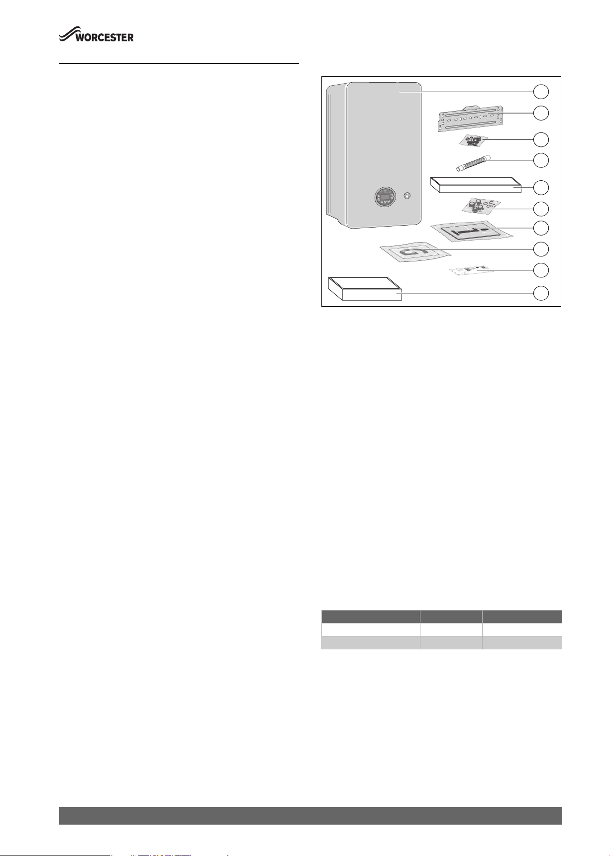
3.2 Scope of delivery
1
2
3
4
5
6
7
8
9
10
Fig. 1
[1] Wall mounted gas-fired condensing combi appliance.
[2] Wall mounting bracket.
[3] Fittings pack.
[4] Condensate hose connector.
[5] Valves set.
[6] Compression fitting adapters set.
[7] Literature pack:
– Installation and Maintenance Instructions,
– User Instructions,
– Wall mounting template.
[8] Guarantee card
[9] ErP labels and system fiche.
[10] Comfort+ II RF controller and Key
3.3 Declaration of Conformity
The design and operation of this product comply with European
Directives and the supplementary national requirements. Conformity
has been demonstrated by the CE marking.
You can ask for a copy of the declaration of conformity for this product.
For this see the contact address on the back cover of these instructions.
0010029387-001
Worcester 2000 – 6 721 814 551 (2019/09)
3.4 Appliance type overview
This appliance are for use with:
• Natural Gas (Cat.II 2H type C13, C33 & C53)
This document refers to the following appliance types:
Appliance type Part number Gas Council number
GC2000iW 25 C NG 7 736 902 027 47-800-25
GC2000iW 30 C NG 7 736 902 028 47-800-24
Table 2 Type overview
The name of the appliance consists of the following parts:
• GC2000iW: Type name
• 25 or 30: Hot water output in kW
• C: Combi appliance
• NG: Gas type (Natural Gas)
7
Product Information
3.5 Product identification
Data plate
The data plate includes the product performance information, approval
data and serial number. The data plate location can be found in the
product overview.
Additional type plate
The product name and the most important product data are shown on
the additional data plate. The additional type plate can be found on the
outside of the product in an easily accessible location.
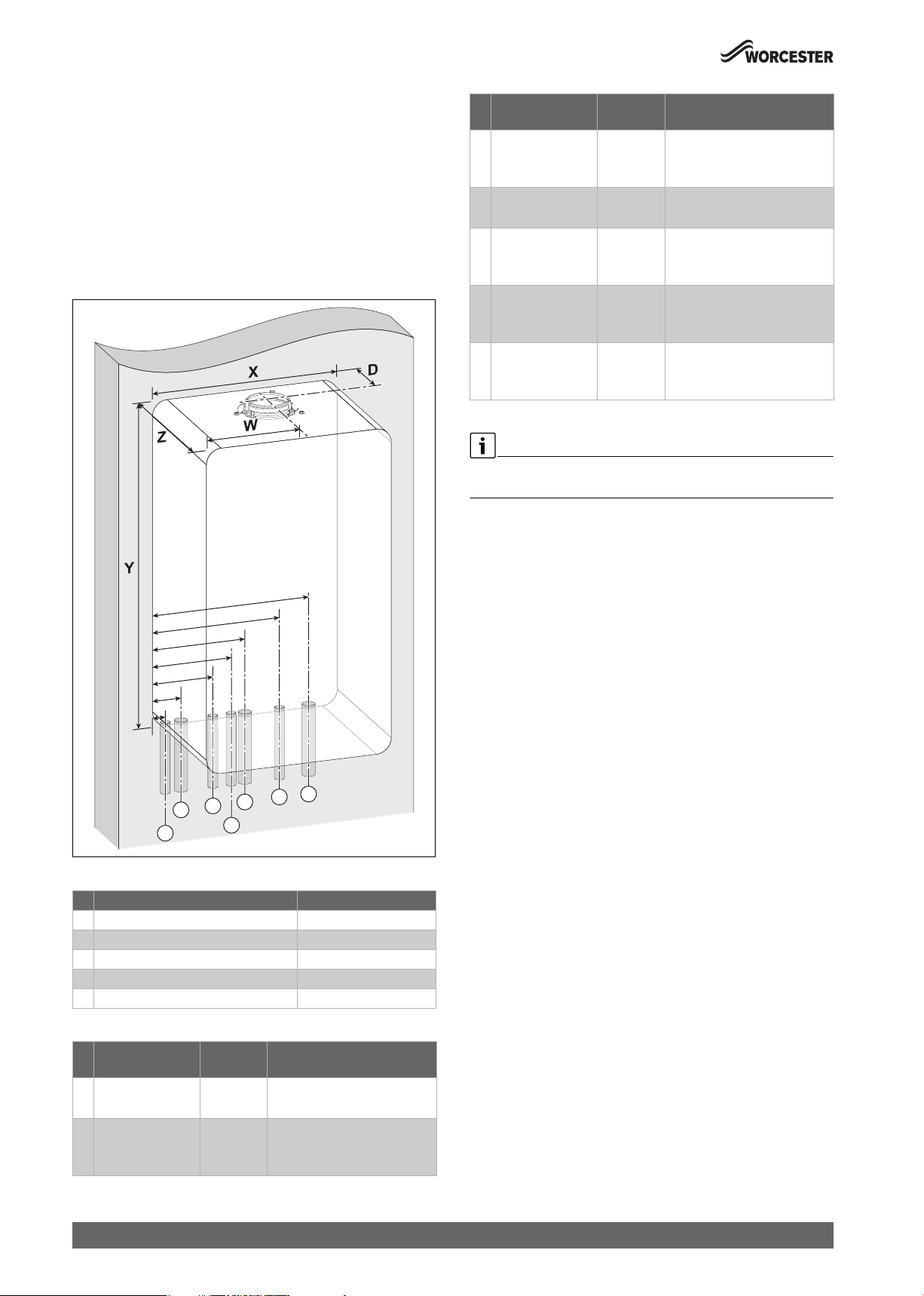
3.6 Pipe work positions and flue outlet
# Function From left
case edge
3 DHW Outlet 133mm 15mm
4 PRV Discharge 172.5mm 15mm
5 Gas 200mm 22mm
6 DCW Inlet 267mm 15mm
7 CH Return 332mm 22mm
Table 4 Pipe dimensions
For servicing purposes, keep condensate and pressure release valve
discharge pipes away from other hydraulic components.
Diameter of pipe
• Compression fitting (via
adaptor)
• Fittings not supplied
• Compression fitting (via
adaptor)
• Compression fitting (via
adaptor)
• Compression fitting (via
adaptor)
7
6
5
3
2
1
Fig. 2 Pipe and flue outlet dimensions
Description Dimensions (mm)
X Appliance width 400
Y Appliance height 724
Z Appliance depth 300
W Flue centre from appliance left side 200
D Flue centre from rear of appliance 125
Table 3 Appliance and flue outlet dimensions
# Function From left
1 Condensate Outlet 60mm 22mm
2 CH Flow 68mm 22mm
4
Diameter of pipe
case edge
• Rubber push fit connection
• Compression fitting (via
adaptor)
0010029389-001
8
Worcester 2000 – 6 721 814 551 (2019/09)
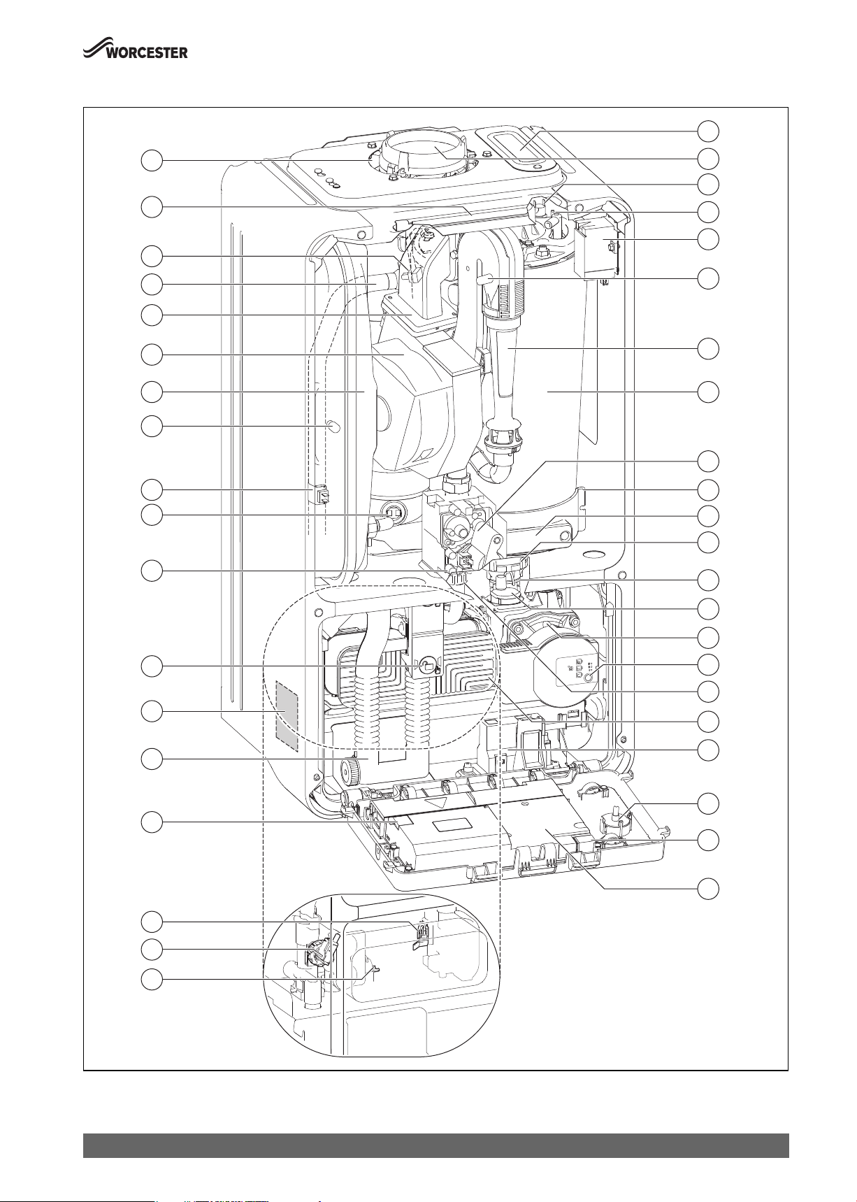
3.7 Product overview
Product Information
1
40
39
38
37
36
35
34
33
32
31
2
3
4
5
6
7
8
9
10
11
12
30
29
28
27
26
25
24
13
14
15
16
17
18
19
20
21
22
23
Fig. 3 Product overview
Worcester 2000 – 6 721 814 551 (2019/09)
0010029397-001
9

Product Information
Legend to figure 3:
[1] Inspection aperture
[2] Flue connection
[3] Heating block temperature limiter
[4] Electrode set
[5] Ignition transformer
[6] Control pressure test point
[7] Gas-air mixing chamber
[8] Heating block
[9] Gas valve
[10] Condensate sump
[11] Cover for inspection aperture
[12] Diverter valve motor
[13] Diverter valve
[14] Automatic air vent
[15] Heating pump
[16] Pump speed adjuster and LED indicator
[17] Pressure relief valve (heating circuit)
[18] Plate heat exchanger
[19] KEY accessory housing (wireless gateway)
[20] Pressure gauge
[21] Position for code plug (KIM)
[22] Control unit
[23] DHW temperature sensor
[24] Pressure switch
[25] Flow turbine
[26] Fuse (replacement)
[27] Condensate trap
[28] Data plate
[29] Condensate trap locking mechanism
[30] Gas supply pressure test point
[31] Flue gas temperature limiter
[32] Flow temperature sensor
[33] Schrader valve
[34] Expansion vessel
[35] Fan
[36] Air-gas manifold with non-return valve
[37] Heating flow
[38] Flow temperature sensor at heating
[39] Bracket
[40] Combustion air intake
3.8 Product data for energy consumption
The product data on energy consumption can be found in the operating
instructions for the user.
3.9 Standard accessories
3.9.1 Appliance accessories
Part number Description
7 716 192 746 Worcester CondenseSure
7 733 600 236 Greenstar System filter (22mm)
7 733 600 237 Greenstar System filter (28mm)
7 733 600 266 Greenstar System filter mini (22mm)
7 733 600 476 Greenstar Brass system filter (22mm)
7 716 192 610 Worcester keyless filling link
7 733 600 091 Heat exchanger cleaning kit
Table 5 Appliance accessories
3.9.2 Programmer/timer accessories
The programmers/timers listed can be used with the appliances stated
on the front of this manual.
Part number Description
7 738 112 324 Comfort +II RF (programmable room
thermostat)
7 738 111 064 Sense II weather compensation controller
1) Preheat time control available
2) Landlord function is not compatible with the Worcester 2000
3) Power and gas consumption will not display accurately on the Comfort+ II RF.
The electricity consumption for both CH and DHW assumes the pump is running
at 100% speed permanently. As a result the indicated consumption will be the
highest possible. Actual consumption is likely to be less.
Table 6 Control accessories
Bosch EasyControl smart control system
Part number Description
7 736 701 341 EasyControl (white)
7 736 701 392 EasyControl (black)
7 736 701 555 EasyControl TRV set (white)
7 736 701 556 EasyControl TRV set (black)
Table 7 EasyControl accessories
1) 2)3)
1)
10
Worcester 2000 – 6 721 814 551 (2019/09)

4 Pre-Installation
NOTICE:
Risk of damage to system or appliance!
Before installation
▶ All the following Pre-Installation sections must be read and
requirements met before starting appliance or flue installations.
4.1 System preparation
4.1.1 Artificially softened water
It is possible to have an ion exchange water softener fitted to the cold
water system of the property. However, the appliance requires an
untreated cold water connection taken from the mains supply, before the
water softener, to the primary water filling point of the heating system.
Alternatively there are water softening/treatment appliances that do not
adjust or alter the pH levels of the water. With these appliances it may not
be necessary to provide an untreated water by-pass to the primary water
filling point of the heat system.
NOTICE:
▶ Salt based softened water must not be used to fill the central heating
system.
4.1.2 Water systems and pipe work
Primary system plastic pipework:
• Any plastic pipe work must have a polymeric barrier, complying with
BS 7921 and installed to BS 5955 with 600mm (minimum) length of
copper connected to the appliance.
• Plastic pipe work used for under-floor heating must be correctly
controlled with a thermostatic blending valve limiting the
temperature of the circuits to approximately 50°C with 1000mm
(minimum) length of copper or steel pipe connected to the
appliance.
Primary system/connections/valves:
• Do not use galvanised pipes or radiators.
• All system connections, taps and mixing valves must be capable of
sustaining a pressure of 3 bar.
• Radiator valves should conform to BS 2767:10.
• All other valves should conform to BS 1010.
• It is best practice to fit Thermostatic Radiator Valves (TRV's) to all
radiators, except the area where the room thermostat is sited which
must be fitted with lockshield valves that are left open.
• The circulating pump speed is fixed therefore as system
circulation can be significantly adjusted or stopped by TRV's or
zone valves, a system bypass must be installed to give at least a
3 metre circuit when activated.
• Drain cocks are required at all the lowest points on the system.
• Air vents are required at all high points on the system.
Showers/Bidets:
• If a shower head can be immersed in water or comes closer than
25mm from the top edge of a bath or shower tray spill-over level then
an anti-siphon appliance must be fitted to the shower hose.
• Bidets with direct hot and cold mains water can be used (with the
approval of the local water authority) and must be the over rim
flushing type with shrouded outlets to prevent the fitting of hand held
sprays.
Hot water:
• Taps and mixing valves must be capable of sustaining a pressure up to
10 bar.
Pre-Installation
• Hot water temperature and flow rate are affected by the size and
insulation of pipe work making up the distribution system and are
controlled by the hot water tap and the water main inlet pressure. A
mixing valve can be fitted if a more permanent temperature setting is
required.
• If using more than one outlet at once causes water flow starvation, fit
flow balancing valves or Ball-O-Fix valves to the appropriate outlets.
Primary system considerations - Combi & System appliances
Sealed system
• The CH sealed system must be filled using a WRAS approved filling
loop or comply with examples in 4.1.4 "System fill" section.
• Where the system volume is more than 100 litres or exceeds 2.5 bar
at maximum heating temperature an additional expansion vessel [2]
must be fitted as close as possible to the appliance in the central
heating return.
• Pressurise the extra expansion vessel [2] to the same value as the
built-in expansion vessel - refer to the Technical data page.
1
2
4
5
3
0010021117-001
Fig. 4 Additional expansion vessel
[1] Appliance expansion vessel
[2] Additional expansion vessel
[3] Pressure relief discharge
[4] Heating return
[5] Heating flow
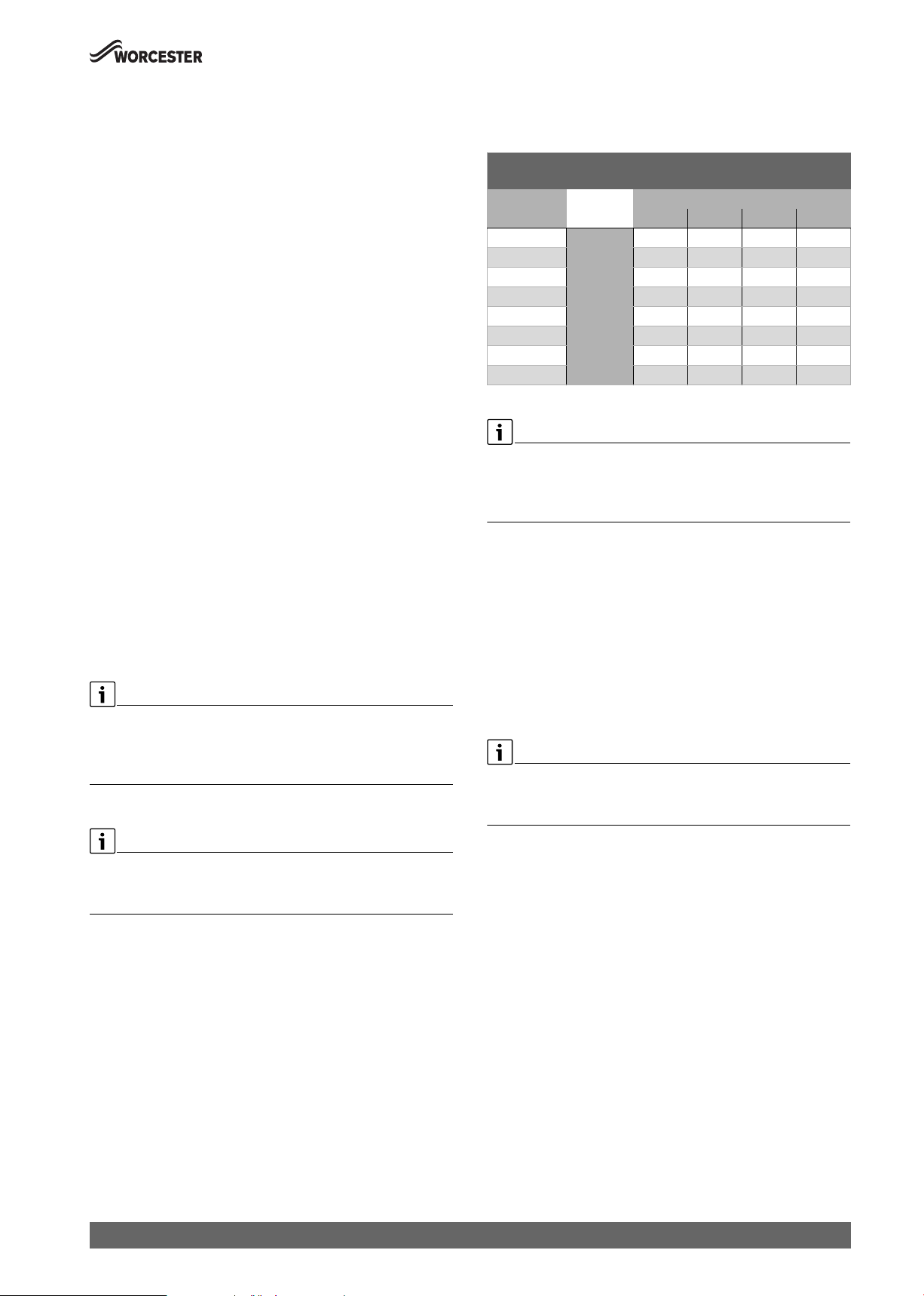
Checking the size of the expansion vessel
To determine whether an additional expansion vessel is required: Follow
the steps below:
▶ Calculate the total system volume (litres).
– Plot a line vertically on the chart ( Fig. 5).
▶ Determine the central heating maximum operating flow temperature.
– Plot a line horizontally on the chart ( Fig. 5).
▶ Determine the pre-charge in the expansion vessel based on static
head, 1 meter = 0.1 bar.
– Static head should be measured between the expansion vessel
and the highest point on the system (top of the highest radiator).
▶ Select a curve from the key below (1-5).
▶ System pressure should be set at 0.1 - 0.25 bar higher than the
vessel pre-charge.
– It must be at least to the minimum on appliances with an analogue
gauge.
– Minimum pressure settings may need to be adjusted to suit on,
appliances with a digital gauge, in the applicable menu function.
– Intelligent filling settings may need to be adjusted to suit on,
appliances with the automatic filling accessory, in the applicable
menu function.
If the dissected lines are in area A then no additional expansion is
required.
If the dissected line is in are B then an additional expansion vessel must
be installed ( Fig. 4).
Worcester 2000 – 6 721 814 551 (2019/09)
11

Pre-Installation
T[°C]
90
Sealed primary system - 2 x central heating zones:
• Requirement for new builds if the floor area of a property is over
150m
2
.
80
70
60
5
4
B
3
2
50
1
A
40
30
0 100 200 300 400 500
Fig. 5 Curves for the expansion vessel
1 Pre-charge pressure 0.5 bar (minimum)
2 Pre-charge pressure 0.75 bar
3 Pre-charge pressure 1.0 bar
4 Pre-charge pressure 1.2 bar
5 Pre-charge pressure 1.3 bar
A Operational capacity of the expansion vessel (left of the relevant
curve)
B Additional expansion vessel required (right of the relevant curve)
T Maximum operating temperature [ °C]
V Total System Volume [l]
The default pre-charge pressure for the appliance is 0.75 bar
600 700
V[l]
0010016558-002
2
2
1
Fig. 7 Separated heating zones
[1] Appliance
[2] Zone valves
4.1.4 System fill
Integral filling link
• An optional filling link accessory is available to fill the system.
– Refer to filling link instructions for fitting and operation.
Filling primary sealed systems
NOTICE:
Filling the primary sealed system
The system must not be filled with salt based softened water.
▶ Ensure the primary water filling point uses an untreated cold water
connection from the mains supply, before a water softener.
0010021228-002
4.1.3 System layouts examples
Sealed primary system - Single central heating circuit:
Typical primary system example
1
Fig. 6 Single central heating circuit example
[1] Appliance
0010021227-002
• Filling the system must comply with one of the following methods
shown.
• The filling point must be at low level and must never be a permanent
connection to the mains water supply.
• Filling loops must be WRAS approved.
• If the external filling link is sited away from the appliance, then a
pressure gauge should be installed at the filling point.
External filling loop
1
3 3
4
Fig. 8 External filling loop system fill example
[1] Cold mains inlet pipe
[2] Stop valve
[3] Check valve
[4] Test point
[5] Hose union
[6] Central heating flow pipe
5
6
22
0010012942-001
12
Worcester 2000 – 6 721 814 551 (2019/09)
Pre-Installation
4.2 Mains supply
4.2.1 Electrical supply
• Supply: 230V AC - 50 Hz
• This appliance must not be connected to a three phase supply.
• The wiring between the appliance and the electrical supply must
comply with the latest IET wiring regulations that apply to wiring a
fixed appliance for Class 1 equipment.
• The correct type of RCD must be employed where additional
protection is required that is suitable for a low energy DC modulating
pump according to IET wiring regulations.
• External 3 A fuse to BS1362.
• The appliance must be earthed.
• Cable: PVC insulated 0.75mm
90 °C, to BS EN50525.
• Any additional components that are connected to the appliance with
mains electrical supply must not have a separate supply.
• Additional equipment wired to the appliance must comply with the
latest IET wiring regulations.
• Appliance protection rating - IPX4D
4.2.2 Gas supply
• Appliances using Natural Gas (NG) must be connected to a governed
meter.
• Installation and connection of the gas supply to the appliance must
be in accordance with the latest version of BS6891.
• Gas pipe sizing should be calculated to ensure no more than the
permitted mbar drop between the meter to the appliance inlet. (
chapter 6).
• The meter and pipe work to the meter must be checked, preferably by
the gas supplier. This is to ensure that the equipment is in good
working order and can meet the gas flow and pressure requirements,
in addition to the demand from any other appliance being served.
Pipe sizing (NG)
Gas pipe work:
▶ Gas installation pipe work must be designed to ensure the pressure
loss between the meter outlet (NG) table 20 ”Allowed mbar
pressure drop”.
Basic pipe sizing calculation
2
(24 x 0.2mm) temperature rated to
Natural Gas (NG):
Discharge rates for copper tube with 1mbar differential pressure
between the ends for Natural Gas.
Discharge rates for Natural Gas (m3/hr)
with straight horizontal copper tube
Pipe Pipe Size (mm)
Length (m) 15 22 28 35
3
2.9 8.7 18 32
6 1.9 5.8 12 22
9
1.5 4.6 9.4 17
12 Discharge 1.3 3.9 8 15
15
m3/hr 1.1 3.4 7 13
20 0.95 2.9 5.9 11
25
0.92 2.5 5.2 9.5
30 0.88 2.3 4.7 8.5
Table 8 Natural Gas
Natural Gas:
▶ When using this table to estimate the gas flow rate in pipe work of a
known length, the effective length will be increased by 0.5m for each
90° elbow and tee fitted and by 0.3m for each 90° bend.
4.2.3 Water supply
Use in hard water areas:
Normally there is no need for water treatment to prevent scale formation
as the maximum temperature of the HW heat exchanger is limited by the
electronic control.
In areas where temporary water hardness exceeds 200ppm,
consideration may need to be given to the fitting of a scale prevention
appliance. In such circumstances, the advice of the local water authority
should be sought.
Keyless filling link accessory
Minimum static pressure.
▶ A minimum static pressure of 1.75bar is recommended for correct
operation of the Keyless filling link.
Basic pipe sizing calculation.
▶ This method is only a guide - for more complex design please
refer to latest version of BS6891 and training given in ACS.
Worcester 2000 – 6 721 814 551 (2019/09)
13
Pre-Installation
Water mains pressure:
• Minimum mains water pressure, for maximum performance refer to
section 13.1 "Technical data".
• Maximum mains fed water static pressure 10 bar.
If necessary fit a pressure reducing valve.
NOTICE:
Non return, back flow prevention appliances (including those
associated with water meters) fitted to the mains water supply can
cause a pressure build up which could damage the appliance and
other household appliances.
NOTICE:
Non return valves in the cold water feed system.
If a non return valve is fitted on the mains inlet, then pressure can
increase significantly over normal standing pressure when the appliance
carries out a HW preheat or due to fast acting valves closing on other
appliances/outlets.
▶ To ensure water pressure stays at a level that will not damage the
appliance or other household appliances, we would recommend that
a 3bar pressure reducing valve and mini expansion vessel are fitted.
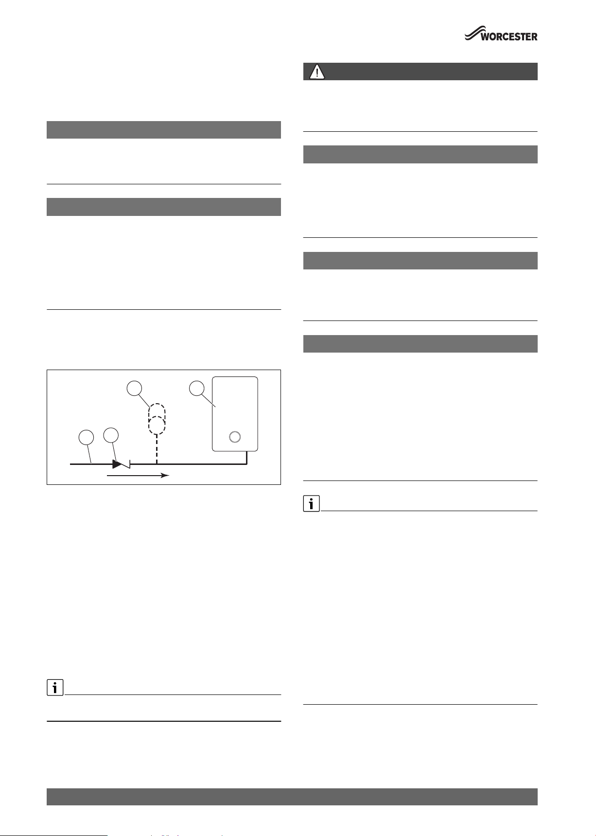
• Where the mains water supply has a non-return, back flow prevention
valve fitted, a mini expansion vessel [3] should be connected to the
mains water inlet pipe [1] between the non-return valve [2] and the
appliance[4] as shown below.
3 4
2
1
0010015563-001
DANGER:
Danger from explosive and flammable materials:
Storage of explosive and flammable materials.
▶ Do not store flammable materials (paper, curtains, clothing, primer,
paint, …) in proximity to the appliance.
NOTICE:
Damage to appliance:
Contaminated combustion air.
▶ Do not use any cleaners containing chlorine or hydrogen halide (i.e.
spray cans, primers, cleaners, paint and glue).
▶ Do not store or use these substances in the appliance, room.
▶ Avoid the build up of dust.
NOTICE:
Damage to appliance:
Extreme temperatures may cause damage to the heating system.
▶ Ensure the appliance location’s ambient temperature is above 0 °C
and below 50°C.
NOTICE:
Damage to system:
The heating system pipe work can be damaged by frost if installed in an
internal unheated area, such as a loft, basement or garage.
The appliance internal frost protection only monitors the system water
temperature within the appliance to provide protection for the
appliance.
▶ No system frost protection available.
▶ The system pipe work in the internal unheated area should be
insulated.
▶ If the appliance is to be shut down for an extended period, drain the
central heating system.
Fig. 9 Mini expansion vessel location
[1] Mains water inlet pipe
[2] Non-return valve
[3] Mini expansion vessel - part no. 7 716 192 105
[4] Appliance
4.3 Appliance location and clearances
4.3.1 Appliance location
• Follow local regulations for the location within the property that the
appliance is to be installed.
• This appliance is only suitable for installing internally within a
property at a suitable location onto a flat, fixed rigid surface capable
of supporting the appliance weight.
• The appliance is not suitable for external installation.
• Protect installation area against dust and moisture.
• Provide fresh air.
No surface protection is required against heat transfer from the
appliance
The appliance must be installed where:
▶ The area is well lit, allowing to clearly see the appliance to carry out
any work or checks.
▶ An engineer can gain clear and safe access to work on the product or
component, including making adequate provision for visual
inspection of flues in voids.
▶ The homeowner can gain clear and safe access to the controls, check,
top up or reset the appliance.
▶ Roof space installations must fully conform to BS 5410 part 1: roof
space installations.
▶ Products in roof spaces must have permanent fixed lighting, a
permanent fixed retractable ladder and a fixed floor area sufficient to
allow access for normal use and servicing around the product and
between and the access hatch.
We would also recommend that a remote pressure gauge and filling
loop are sited where the customer can gain easy access for checking
and topping up.
14
Worcester 2000 – 6 721 814 551 (2019/09)
4.3.2 Rooms containing a bath or shower
CAUTION:
Risk of electric shock
▶ Any switch or appliance control using mains electricity must not be
within reach of a person using the bath or shower.
• In all cases the installation must be in accordance with the latest
amendments to the latest edition of the IET Wiring Regulations
(BS7671).
• Check the IP rating of any control units to be used on this appliance.
• Circuit breaking devices should be used in accordance with the
regulations.
• Figure 10 is for guidance only.
600mm
Pre-Installation
600mm
600mm
1
1
2*
2250mm
2*
A
2
2
1
2
A
A
0010017086-001
Fig. 10 Bathroom installations
[1] Zone 1
[2] Zone 2
[2*] Without the end wall, zone 2 must extend 600mm from the bath
[A] 600mm radius from the bath or shower
• Appliance protection rating - IPX4D
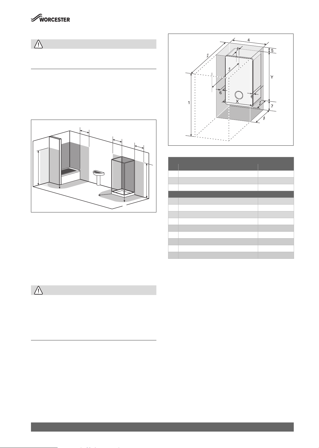
4.3.3 Appliance clearances
Appliance clearances
• The following details covering the installation, service and
maintenance clearances for the appliance.
CAUTION:
Risk of damage to appliance or property
The appliance will overheat if the clearance space around the appliance
is restricted by objects.
▶ Do not restrict this space with the addition of cupboards, shelves etc.
next to or around the appliance.
▶ Do not store any combustible materials on or next to the appliance,
such as clothes, towels, paper or plastic bags.
Fig. 11 Appliance minimum clearances
Minimum clearances
Description Dimensions (mm)
X Appliance width 400
Y Appliance height 724
2250mm
Z Appliance depth 300
Installation/Maintenance
1 Overall clearance height 1115/1155
2 Overall clearance depth 850
3 In front of appliance 600
4 Overall clearance width 410
5 Above the appliance 191/231
6 Either side of appliance 5
7 Below the appliance 200
8 Compartment depth 320
9 Appliance to removable door 20
1) Height for either 60/100 flue or 80/125 flue
Table 9 Appliance minimum clearances
Appliances in compartments
Follow the latest requirements of BS6798 and BS5440 and note:
• Minimum clearances must be maintained.
• An access door is required to install, service and maintain the
appliance and any ancillary equipment.
• If the appliance is installed in an unventilated airing/storage
cupboard, there is no requirement to make a partition between the
appliance and the storage space as long as the minimum clearances
around the appliance are maintained.
0010012940-001
1)
1)
Worcester 2000 – 6 721 814 551 (2019/09)
15
Pre-Installation
4.4 Flue systems considerations
WARNING:
Flue systems
Possible flue gas escape
▶ Use Worcester, Bosch Group approved Condensfit II flue systems
only, no other manufacturer’s flue have been tested or approved for
use with Worcester, Bosch Group appliances.
CAUTION:
Concealed flue systems:
▶ Where a flue system is going to be concealed, provision must be
made for service and inspection.
▶ Voids containing concealed flues must have at least one inspection
hatch no less than 300mm square.
▶ Flue joints within the void must not be more than 1.5 metres from the
edge of the inspection hatch.
▶ Inspection hatches should be located at changes of direction.
▶ If this is not possible, bends should be viewable from both directions.
Refer to the manual supplied with the Worcester, Bosch Group flue kit for
complete installation instructions.
Flue kit part numbers
Part number Flue Ø Description
7 716 191 082 60/100 Telescopic horizontal flue kit
7 716 191 171 60/100 Extended telescopic horizontal flue kit
7 733 600 048 60/100 Horizontal high level telescopic flue kit
7 719 003 702 80/125 Telescopic horizontal flue kit
7 719 002 430 60/100 Vertical balanced flue kit
7 719 002 431 80/125 Vertical balanced flue kit
Table 10 Flue kit assembly part numbers
4.4.1 Flue length
Horizontal maximum flue lengths
Flue length [L] Flue length [L]
Appliance 60/100 80/125
GC2000iW 25 C 9,000mm 12,000mm
GC2000iW 30 C 9,000mm 12,000mm
Table 11 Maximum flue lengths - Horizontal flues
Effective flue length
Bend 60/100 80/125
45° 1m 1m
90° 2m 2m
Table 13 Effective length of bends
4.4.2 Flue options
The systems have different maximum flue lengths, refer to the following
example flue options for those maximum flue lengths.
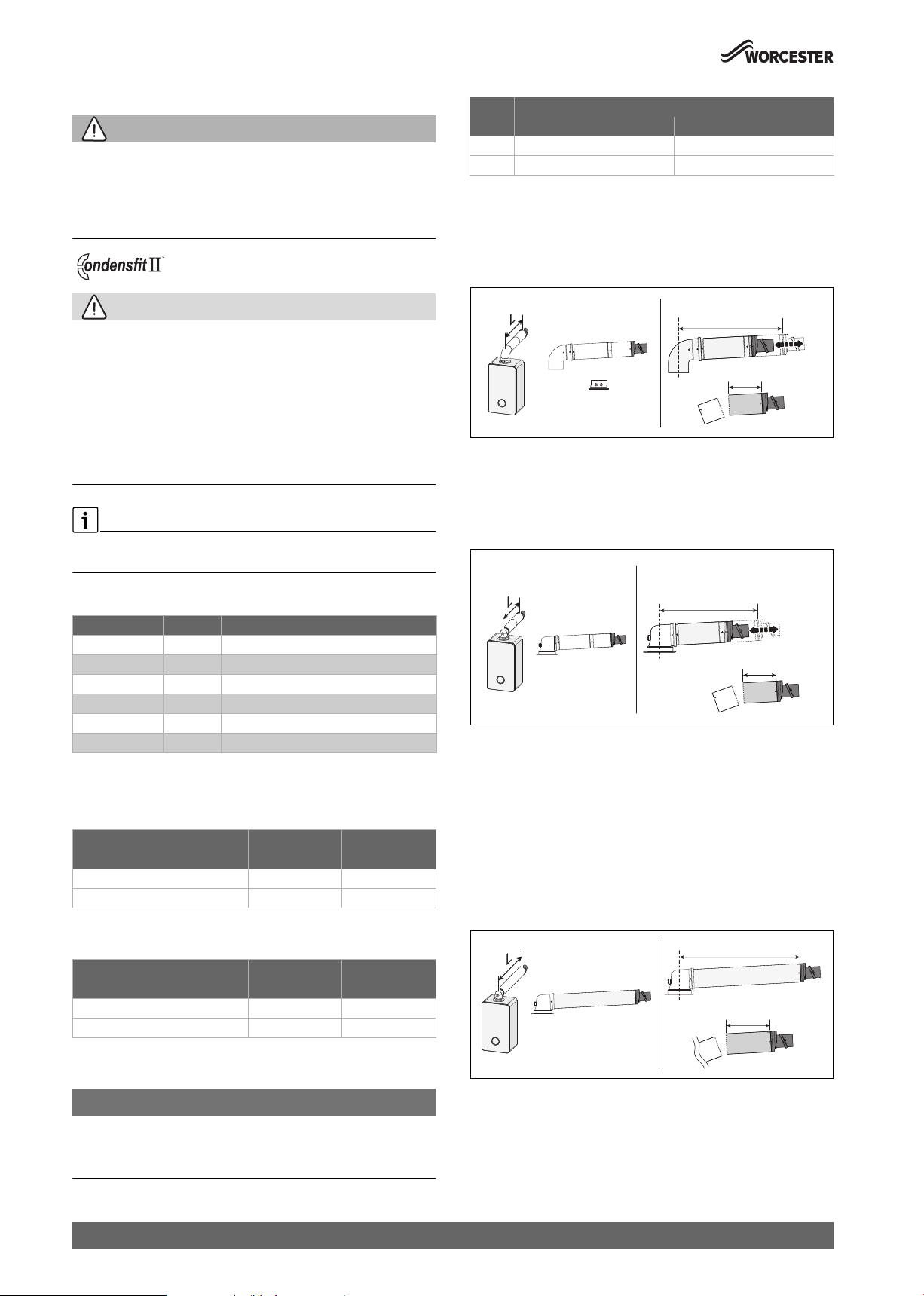
Horizontal high level flue assembly
60/100 mm
383 mm - 603 mm
130 mm Min
0010015190-001
Fig. 12 Horizontal flue option
• Flue length [L] (initial bend included in length calculation)
– 60/100 = 202 - 603mm
– 80/125 = N/A
Telescopic horizontal flue assembly
60/100 mm
[A] 350 mm - 570 mm
[B] 570 mm - 790 mm
130 mm Min
0010015191-001
Fig. 13 Horizontal flue option
Telescopic horizontal flue assembly [A]
• Flue length [L] (adaptor bend included in length calculation)
– 60/100 = 180 - 570mm
– 80/125 = 405 - 600mm
Extended telescopic horizontal flue assembly [B]
• Flue length [L] (adaptor bend included in length calculation)
– 60/100 = 570 - 790mm
– 80/125 = N/A
Horizontal fixed length flue assembly
Vertical maximum flue lengths
Flue length [L] Flue length [L]
Appliance 60/100 80/125
GC2000iW 25 C 12,000mm 15,000mm
GC2000iW 30 C 12,000mm 15,000mm
Table 12 Maximum flue lengths - Vertical flues
Flue system bends
NOTICE:
Effective flue lengths of bends:
Each bend used has an equivalent straight flue length.
▶ Refer to the table 13.
16
1050 mm
330 mm Min
0010015192-001
Fig. 14 Horizontal flue option
• Flue length [L] (adaptor bend included in length calculation)
– 60/100 = 330 - 1,050mm
– 80/125 = N/A
Worcester 2000 – 6 721 814 551 (2019/09)
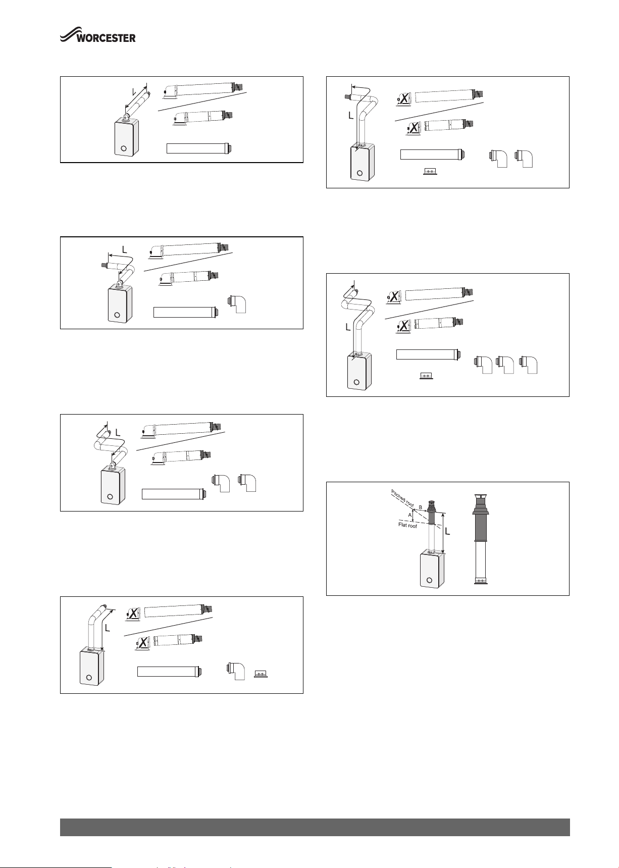
Pre-Installation
A
Extended horizontal flue
0010015193-001
Fig. 15 Horizontal flue option
• Flue length [L] (adaptor bend included in length calculation)
– Maximum flue length as stated in "Horizontal maximum flue
lengths".
Horizontal flue with additional 90° elbow
0010015194-001
Fig. 16 Horizontal flue option
• Flue length [L] (adaptor bend included in length calculation)
– Maximum flue length as stated in "Horizontal maximum flue
lengths" minus the 90° bend equivalent straight flue length as
stated in Table 13 "Effective length of bends".
Horizontal flue with additional 90° elbows
High level horizontal flue with additional 90° elbow
0010015197-001
Fig. 19 Horizontal flue option
• Flue length [L] (initial bend included in length calculation)
– Maximum flue length as stated in "Horizontal maximum flue
lengths" minus the 90° bend equivalent straight flue length as
stated in Table 13 "Effective length of bends".
High level horizontal flue with additional 90° elbows
0010015198-001
Fig. 20 Horizontal flue option
• Flue length [L] (initial bend included in length calculation)
– Maximum flue length as stated in "Horizontal maximum flue
lengths" minus 2 x 90° bends equivalent straight flue length as
stated in Table 13 "Effective length of bends".
0010015195-001
Fig. 17 Horizontal flue option
• Flue length [L] (adaptor bend included in length calculation)
– Maximum flue length as stated in "Horizontal maximum flue
lengths" minus 2 x 90° bends equivalent straight flue length as
stated in Table 13 "Effective length of bends".
High level horizontal flue
Fig. 18 Horizontal flue option
• Flue length [L] (initial bend included in length calculation)
– Maximum flue length as stated in "Horizontal maximum flue
lengths".
Vertical balanced flue assembly
= 300 mm
B = 500 mm
0010015199-001
Fig. 21 Vertical flue option
• Flue length [L]
– Maximum flue length as stated in "Vertical maximum flue
lengths".
0010015196-001
Worcester 2000 – 6 721 814 551 (2019/09)
17
Pre-Installation
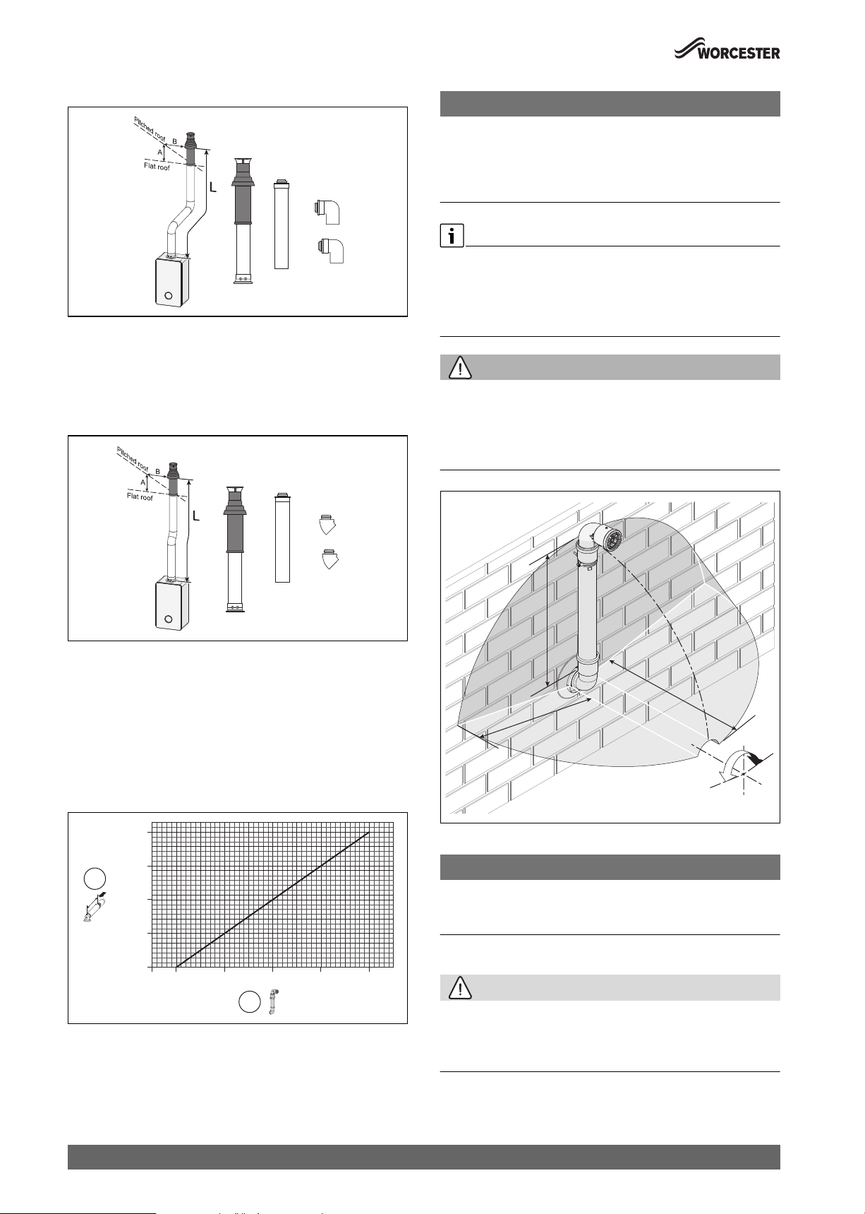
A
A
Vertical balanced flue with 90° elbow offset
= 300 mm
B = 500 mm
0010015200-001
Fig. 22 Vertical flue option
• Flue length [L]
– Maximum flue length as stated in "Vertical maximum flue lengths"
minus 2 x 90° bends equivalent straight flue length as stated in
Table 13 "Effective length of bends".
Vertical balanced flue with 45° elbow offset
NOTICE:
Plume management length:
▶ The plume management length must be a minimum of 500mm and
must not exceed the maximum straight length for a horizontal Ø 60/
100mm flue with a 60mm plume management system as stated
previously.
Horizontal plume management runs
▶ The initial horizontal run from the terminal elbow must have a
minimum 10° fall back, (stop tabs in the elbow prevent less than 10°)
to the appliance for proper disposal of condensate.
▶ Any further horizontal runs after an elbow can be 3°.
WARNING:
Minimum plume management length:
The minimum distance of 500mm must be maintained between air inlet
and exhaust.
▶ Do not terminate the plume management inside the terminal
exclusion zone (shaded area) shown in figure 25.
= 300 mm
B = 500 mm
0010015201-001
Fig. 23 Vertical flue option
• Flue length [L]
– Maximum flue length as stated in "Vertical maximum flue lengths"
minus 2 x 45° bends equivalent straight flue length as stated in
Table 13 "Effective length of bends".
4.4.3 Plume management system
For every extra 1,000mm of plume management after the first 500mm,
the internal 60/100 flue length must be reduced by 700mm, up to a
maximum of 4,500mm of plume management.
2,800
2,100
1
1,400
[mm]
Fig. 24 Reduction to flue length as plume length increases graph
[1] Reduction to flue length [mm] (maximum reduction 2,800mm)
[2] Plume length [mm] (maximum plume length 4,500mm)
700
0
500 1,500 2,500 3,500 4,500
[mm]
2
0010023114-001
m
m
00
5
5
0
0
m
m
mm
00
5
±80°
0010013548-001
Fig. 25 Terminal exclusion zone
NOTICE:
Cutting the 500mm pipe
▶ The Plume management extension kit contains the components
required for such a configuration.
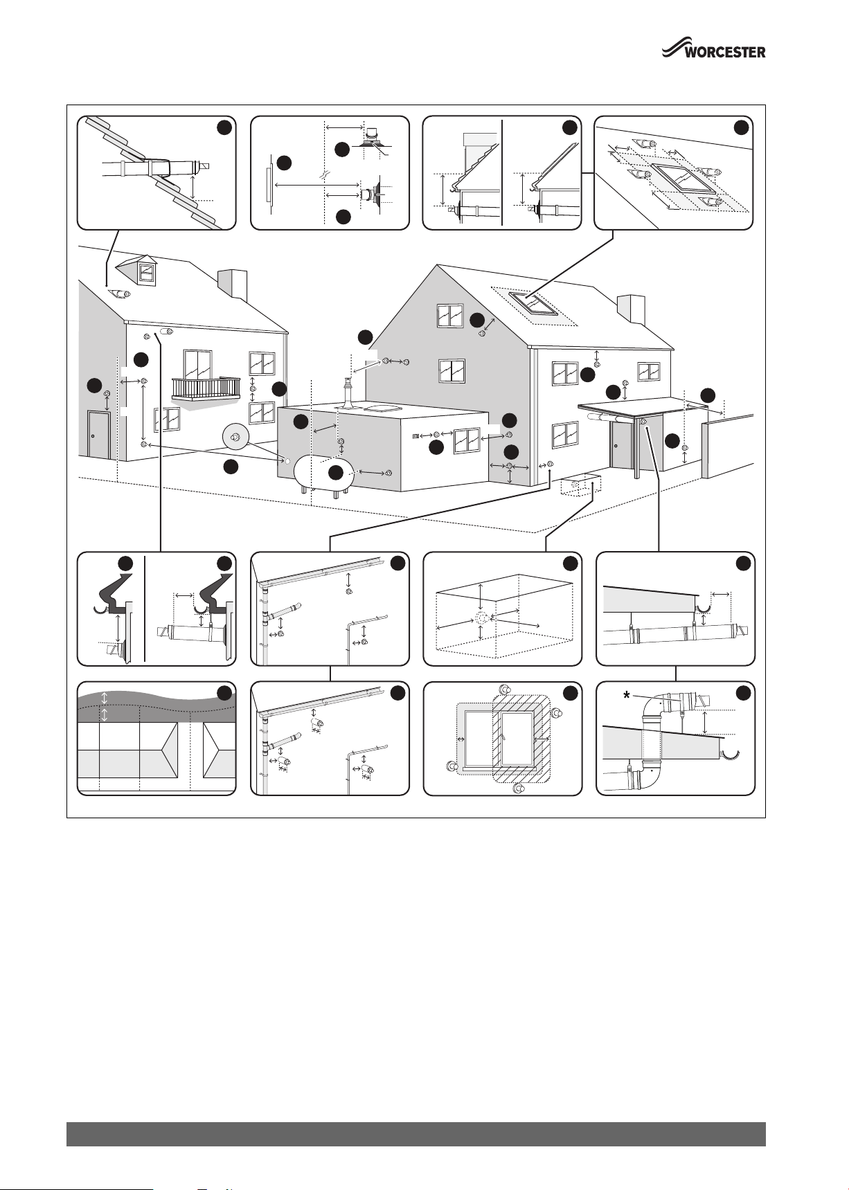
4.4.4 Flue terminal positions
CAUTION:
Flue terminal positions
▶ All measurements are the minimum clearances required.
▶ Terminals must be positioned so to avoid combustion products
entering the building.
18
Worcester 2000 – 6 721 814 551 (2019/09)
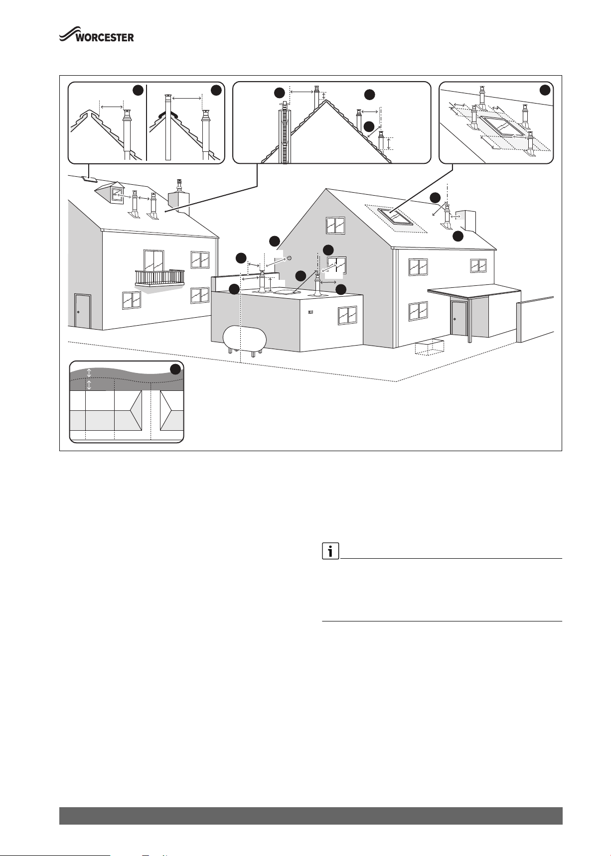
Vertical flue terminal positions
Pre-Installation
1/2
1/2
1500
1500
RIDGE FLUERIDGE VENT
1
600
BOUNDARY LINE
BOUNDARIES
9
1500
2
5
300
3
500
8
1200
300
2
1500
4
600
300
10
1500
500
2
600
400
7
300
5
400
600
600
7
500
5
2000
600
1500
6
Fig. 26 Vertical flue terminal positions
Key to figure 26:
[1] 1,500mm measured between a vertical flue terminal and an
opening or vented window. 500mm measured horizontally
between a vertical flue terminal and an opening or vented window
providing the flue terminal is at least 300mm above the opening.
[2] Minimum clearance to an additional flue, 600mm to a room
sealed flue or 1,500mm to an open flue.
[3] 300mm clearance from a vertical flue terminal adjacent to a
boundary line, unless it will cause a nuisance. BS 5440: Part 1
recommends that care is taken when siting a terminal in relation to
boundary lines.
[4] 600mm minimum clearance measured from an opening or vented
skylight to a vertical flue terminal. If the terminal is within
1,500mm of the opening or vented skylight then it must be at
least 300mm above the opening.
[5] 500mm clearance measured horizontally from a vertical flue to a
vertical structure.
Not required if the terminal is 300mm above the structure.
[6] The flue must not penetrate the roof in the shaded area.
The terminal must be at least 1,500mm from the opening or vent
when sited below the window or 600mm when sited to either side
or above.
[7] 400mm measured diagonally from a pitched roof or 500mm in
regions with heavy snow fall. 300mm measured vertically from
the air intake to the closest intersection with the roof.
[8] 1,200mm separation measured between a vertical flue and a
horizontal flue terminal.
[9] For the purpose of determining suitable flue terminal positions for
gas appliances, the boundary can be considered to extend to the
0010021441-002
centre line of any adjacent routes or waterways e.g. paths,
streets, rights of way, canals, rivers or railways.
[10] 1,500mm measured between a vertical flue terminal and an
opening or vented window. 500mm measured horizontally
between a vertical flue terminal and an opening or vented window
providing the flue terminal is at least 300mm above the opening.
Note:
▶ Where a vertical flue terminates in an area that is enclosed on 3 sides,
the flue must be no more than 1,000mm below the lowest roof line.
You must ensure that all clearances are maintained and that products
of combustion disperse safely from the area.
Worcester 2000 – 6 721 814 551 (2019/09)
19
Pre-Installation
Horizontal flue terminal positions
11
300
300
1500
300
10
BOUNDARY LINE
OPENING
OPPOSITE
14
2000
300
3
600
TOP
TOP
600
600
SKYLIGHTDORMA
6
600
600
600
1500
6
5
1
600
200
300
10
200
1
10
300
7
5
600
10
25
300
300
8
600
13
300
1200
1000
300
300
300
11
3
300
11
300
5
1200
4
BOUNDARY LINE
200
1/2
1/2
1
100
BOUNDARIES
2
25
9
Fig. 27 Horizontal flue terminal positions
1
200
75
25
75
25
BELOW GROUND OPEN LIGHT WELL
<1000
300
300
300
2
25
100
25
25
100
25
25
100
12
600
15
300150
16
100
25
10
300
0010021442-002
20
Worcester 2000 – 6 721 814 551 (2019/09)

Key to figure 27:
[1] 200mm below eaves and 75mm below gutters, pipe and drains.
[2] The dimension below eaves, gutters, pipes and drains can be
reduced to 25mm, as long as the flue terminal is extended by
100mm past any overhang. The telescopic flue joint must be
sealed with suitable silicone sealant if it is external to the building.
[3] 300mm adjacent to a boundary line, unless it will cause a
nuisance. BS 5440: Part 1 recommends that care is taken when
siting terminal in relation to surfaces or boundary lines.
[4] 1,200mm separation measured between terminals facing each
other.
[5] 600mm distance to a surface or boundary line facing a terminal,
unless it will cause a nuisance. BS 5440: Part 1 recommends that
care is taken when siting terminal in relation to surfaces or
boundary lines.
[6] The terminal must be at least 1,500mm from the opening or vent
when sited below the window or 600mm when sited to either side
or above.
[7] 600mm diagonally to an opening door, air vent or opening
window.
[8] 1,200mm separation measured between a vertical flue and a
horizontal flue terminal.
[9] For the purpose of determining suitable flue terminal positions for
gas appliances, the boundary can be considered to extend to the
centre line of any adjacent routes or waterways e.g. paths,
streets, rights of way, canals, rivers or railways.
[10] 300mm to an internal or external corner. 300mm above a
surface, such as the ground/ floor level or roof surface.
* If the terminal section is less than 150mm and has two screws
securing it to the elbow, the terminal section will not require a
supporting bracket.
[11] 300mm above, below and either side of an opening door, air vent
or opening window.
[12] Below ground level in an open lightwell. The flue must be at least
600mm from the opposing surface and have at least 300mm
clearance either side and below. The flue terminal must be no
more than 1,000mm from the top of the lightwell.
[13] Flues should clear any LPG storage by 1,000mm horizontally and
300mm above.
[14] Proximity of flue duct outlet to boundaries, 2,000mm distance to
an opening in adjacent building facing a terminal. BS 5440: Part
1 recommends that care is taken when siting terminal in relation
to boundary lines.
[15] 300mm from an opening or vented window, 150mm to a fixed
unvented window.
[16] The dimension below eaves, balconies and car ports can be
reduced to 25mm, as long as the flue terminal is extended to clear
any overhang. The telescopic flue joint of the terminal must be
sealed with suitable silicon sealant if it is external to the building.
Pre-Installation
Note:
▶ Installations in car ports are not recommended.
▶ The flue cannot be lower than 1,000mm from the top of a light well
due to the build up of combustion products.
▶ Dimensions from a flue terminal to a fanned air inlet to be determined
by the ventilation equipment manufacturer.
▶ A flue terminal guard shall be fitted whenever a terminal or air inlet is
fitted less than 2,000mm above ground, above a balcony or above a
flat roof to which people have access.
Worcester 2000 – 6 721 814 551 (2019/09)
21
Pre-Installation
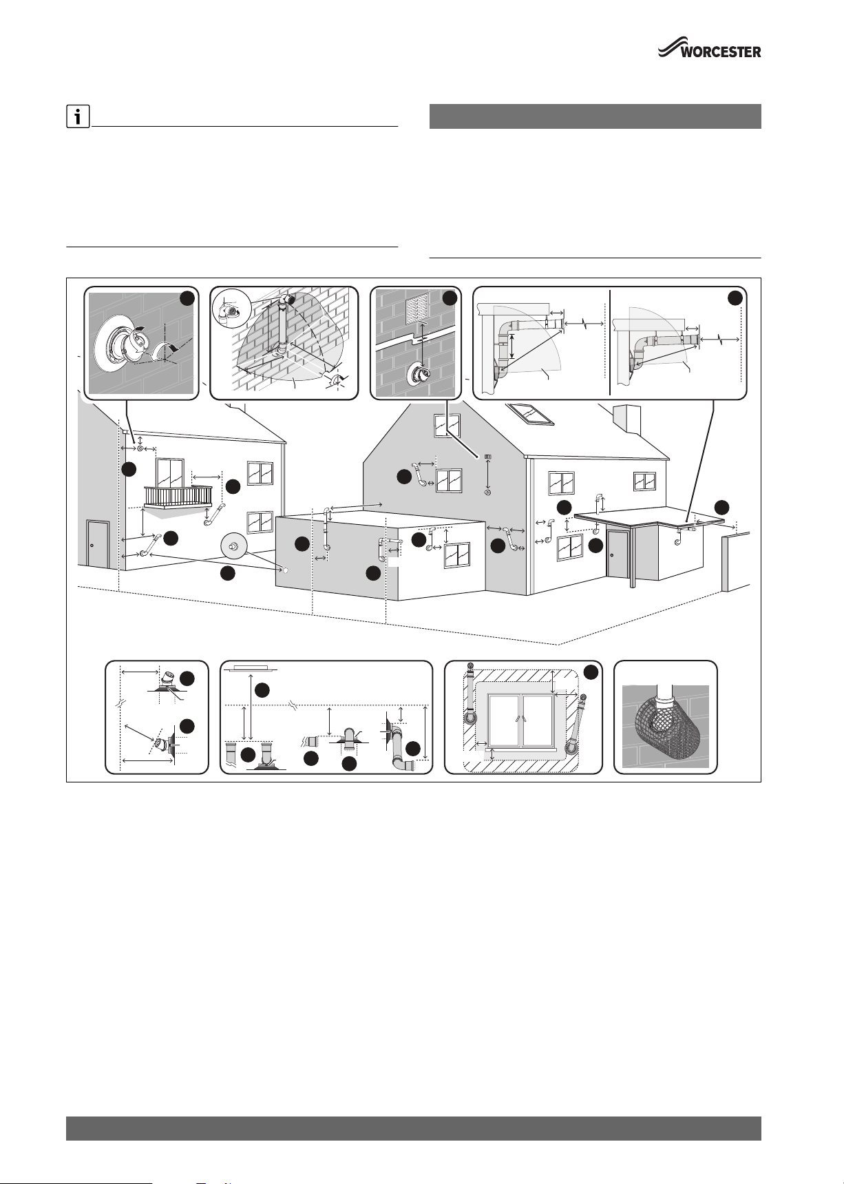
4.4.5 Plume re-direct and plume management terminal positions
Maximum and minimum plume management lengths:
▶ A minimum distance of 500mm must be maintained between the
plume management outlet and the flue air intake.
▶ The maximum plume management length is 4.5 metres for the
appliances detailed on the front of this manual.
▶ The 45° bend is equivalent to 0.75 metres of straight plume
management and the 90° bend is equivalent to 1.5 metres.
NOTICE:
▶ All measurements are the minimum clearances required.
▶ Refer to “Horizontal flue terminal positions” for all concentric flue
terminal positions unless the flue position is specified in figure 28
“Plume re-direct and plume management terminal positions”.
▶ Terminals must be positioned so to avoid combustion products
entering the building.
▶ Support the flue at approximately one metre intervals and at a change
of direction, use suitable brackets and fittings.
180°
±80°
200
300
2
200
300
150
300
600
BOUNDARY LINE
300
1
150
9
BOUNDARY LINE
2
TOP
3
TOP
200
1200
±45°
11
12
2000
600
0
0
5
0
5
6
5
5
0
0
EXCLUSION ZONE
8
OPENING
OPPOSITE
300
7
TOP
0
±80°
600
300
300
BOUNDARY LINE
6
600
5
600
300
10
10
300
150
1,500
150
4
300
1500
300
13
≥140
0
0
≥5
EXCLUSION ZONE
25
25
150
100
14
200
600
15
300
100
00
≥5
EXCLUSION ZONE
7
10
300
150
TOP
8
300
9
150
FLUE TERMINAL GUARD
7 716 191 176
0010021676-001
Fig. 28 Plume re-direct and plume management terminal positions
22
Worcester 2000 – 6 721 814 551 (2019/09)

Pre-Installation
Key to figure 28 - Plume re-direction terminal positions:
[1] This feature allows some basic plume re-direction options on a
standard telescopic horizontal flue terminal.
300mm minimum clearances to a opening e.g. window.
However the minimum clearances to an opening in the direction
that the plume management is facing, must be increased to
1,500mm.
Where the flue is less than 150mm to a drainpipe and plume
redirection is used the deflector should not be directed towards
the drainpipe.
[2] 300mm adjacent to a boundary line, unless it will cause a
nuisance. BS 5440: Part 1 recommends that care is taken when
siting terminal in relation to surfaces or boundary lines.
[3] Where the flow of products of combustion is not at right angles to
the boundary, the 600mm dimension may be measured in the
direction of flow as long as the terminal is not less than 300mm
from the boundary.
[4] When redirecting the flue discharge the terminal end must be at
least 1,500mm from any opening in the direction of the discharge
to prevent combustion products from entering the building.
Key to figure 28 - Plume management terminal positions:
[5] 600mm distance facing a surface or a boundary line, unless it will
cause a nuisance. BS 5440:Part 1 recommends that care is taken
when siting a terminal in relation to surfaces or boundary lines.
[6] Proximity of flue duct outlet to boundaries, 2000mm distance to
an opening in adjacent building facing a terminal. BS 5440: Part
1 recommends that care is taken when siting terminal in relation
to boundary lines.
[7] 300mm adjacent to a boundary line, unless it will cause a
nuisance. BS 5440: Part 1 recommends that care is taken when
siting terminal in relation to surfaces or boundary lines.
[8] 300mm distance from a boundary line to the air intake as long as
the exhaust terminal faces away from the boundary line. The
exhaust terminal must have a minimum 300mm clearance to a
surface below and there must be at least 600mm clearance when
measured horizontally in a straight line from the exhaust terminal
to any other surface.
[9] Plume Management kit air intake can be reduced to 150mm
providing the flue exhaust outlet is no less than 300mm adjacent
to a boundary line.
[10] Above, below and either side of an opening door, air vent or
opening window.
Using a Plume Management kit the air intake measurement can be
reduced to 150mm providing the flue exhaust outlet has a
300mm clearance.
[11] Below balcony or overhang. The air intake clearance can be
reduced to 150mm providing the flue exhaust outlet has a
200mm clearance.
[12] 1,200mm between terminals facing each other
1)
.
[13] Internal/external corners. The air intake clearance can be reduced
to 150mm providing the flue exhaust outlet has a 300mm
clearance.
[14] Clearances no less than 200mm from the lowest point of the
balcony or overhang.
[15] If a plume management kit is installed within the confines of a
carport or other covered, partially enclosed extension, then the
exhaust terminal must be positioned at least 1200mm away from
any opening into the building which is sited within the footprint of
the carport.
If the exhaust terminal is extended at least 300mm beyond the
footprint of the carport then the distance from the terminal to an
opening within the carport can be reduced to 600mm.
The exhaust terminal can also be routed though the roof of the
carport providing 25mm clearance is provided around the flue
pipe to any flammable material and that it extends at least 300mm
above the roof.
The air intake must have a minimum 150mm clearance to any
opening in the building in order to ensure the integrity of the
structure is maintained. If the exhaust terminates within the
footprint of the carport then the carport must have at least 2 sides
completely open. If the exhaust terminates at least 300mm
beyond the footprint of the carport then the carport must have at
least one completely open side. The exhaust terminal must be
positioned to ensure that plume will not cause nuisance or
damage to vehicles and that minimum clear distances in front of
the terminal will not be impeded by vehicles.
Note:
▶ Installations in car ports are not recommended.
▶ The flue cannot be lower than 1,000mm from the top of a light well
due to the build up of combustion products.
▶ Dimensions from a flue terminal to a fanned air inlet to be determined
by the ventilation equipment manufacturer.
▶ Plume kits running horizontally must have at least a 3° fall back to the
appliance for proper disposal of condensate, except or the initial
horizontal run from the terminal.
The initial plume kit horizontal run will have at least a 10° fall back to
the appliance, due to the terminal elbow design, for proper disposal
of the condensate.
1) 600mm in case two plume management kits are used on opposing terminals.
Each terminal should use a minimum length of 500mm plume management.
Worcester 2000 – 6 721 814 551 (2019/09)
23
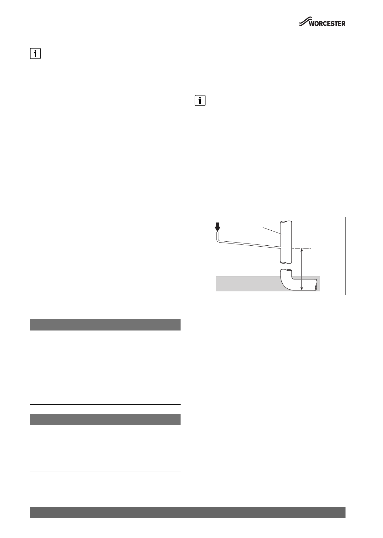
Pre-Installation
4.5 Condensate discharge
Full details on condensate discharge.
▶ Follow the latest version of BS6798 and HHIC guidance.
For correct installation and trouble free operation of the appliance the
following advice should be followed:
1. It is a requirement that the condensate drain is installed
internally.
2. If external disposal is the only means of condensate discharge,
then the CondenseSure siphon or a condensate pump must be
fitted.
3. All condensate pipe work must ‘fall’ from the appliance by a minimum
of 3° (52mm per metre) to ensure adequate condensate flow.
4. The pipe work route must allow air to be supplied back to the
appliance for correct operation.
5. Connection to a rainwater down pipe must include an air break.
Also:
• Assessment of the risk of the condensate pipe freezing must be
carried out and appropriate precautions taken where necessary.
This must take into account the specific site conditions.
• The condensate pipe work connected to the condensate drain outlet
on the appliance should have a minimum internal diameter (ID) of
19mm.
• Keep external pipe work as short as possible.
Further precautions against freezing must be taken if external pipe
runs exceed 3m.
• External pipe work should have a minimum internal diameter (ID) of
30mm.
• Minimise the number of bends and connectors.
• Remove burrs after cutting pipe.
• Remove surplus solvent from the interior of the pipe.
• The condensate pipe work shall be run in standard drainpipe
material, e.g. poly(vinyl chloride) (PVC), unplasticised (vinyl
chloride) (PVC-U), acrylonitrilebutadiene.styrene (ABS),
polypropylene (PP) or chlorinated poly(vinyl chloride) (PVC.C).
4.5.1 Condensate pipe work
NOTICE:
General consideration
▶ Where a new or replacement appliance is being installed, access to
an internal “gravity discharge” point should be one of the factors
considered in determining appliance location.
▶ Condensate pipe connection at the appliance:
The condensate pipe must have a nominally outside diameter of
22mm plastic pipe.
▶ Ensure there are no blockages in the pipe run.
▶ Ensure that the discharge method for the installation can effectively
handle the condensate waste from the appliance.
4.5.2 Condensate production
When the appliance is in operation it can produce between 1 to 2 litres
of condensation per hour.
This discharge is a constant drip feed during the production of
condensate and does not release in frequent large volume discharges
repeatedly.
4.5.3 Internal connections
Good Practice
▶ The following guidance indicates the good practices that must be
maintained for the Installation and Maintenance of a product.
Soil stack connection
Figure 29
In order to minimise risk of freezing during prolonged cold spells, the
following methods of installing condensate drainage pipe should be
adopted.
Wherever possible, the condensate drainage pipe should be routed and
terminated so that the condensate drains away from the appliance under
gravity to a suitable internal foul water discharge point such as an
internal soil and vent stack. A suitable permanent connection to the foul
waste pipe should be used.
1
2
3
0010012746-001
Fig. 29 Disposal to soil vent stack
[1] Condensate discharge from appliance
[2] Soil and vent stack
[3] Minimum 450mm and up to 3 storeys
NOTICE:
Unheated internal areas.
The condensate discharge may freeze in areas during prolonged cold
temperatures.
▶ Internal pipe runs in unheated areas such as lofts, basements and
garages should be treated as external runs and consideration should
be given to using a CondenseSure siphon.
24
Worcester 2000 – 6 721 814 551 (2019/09)
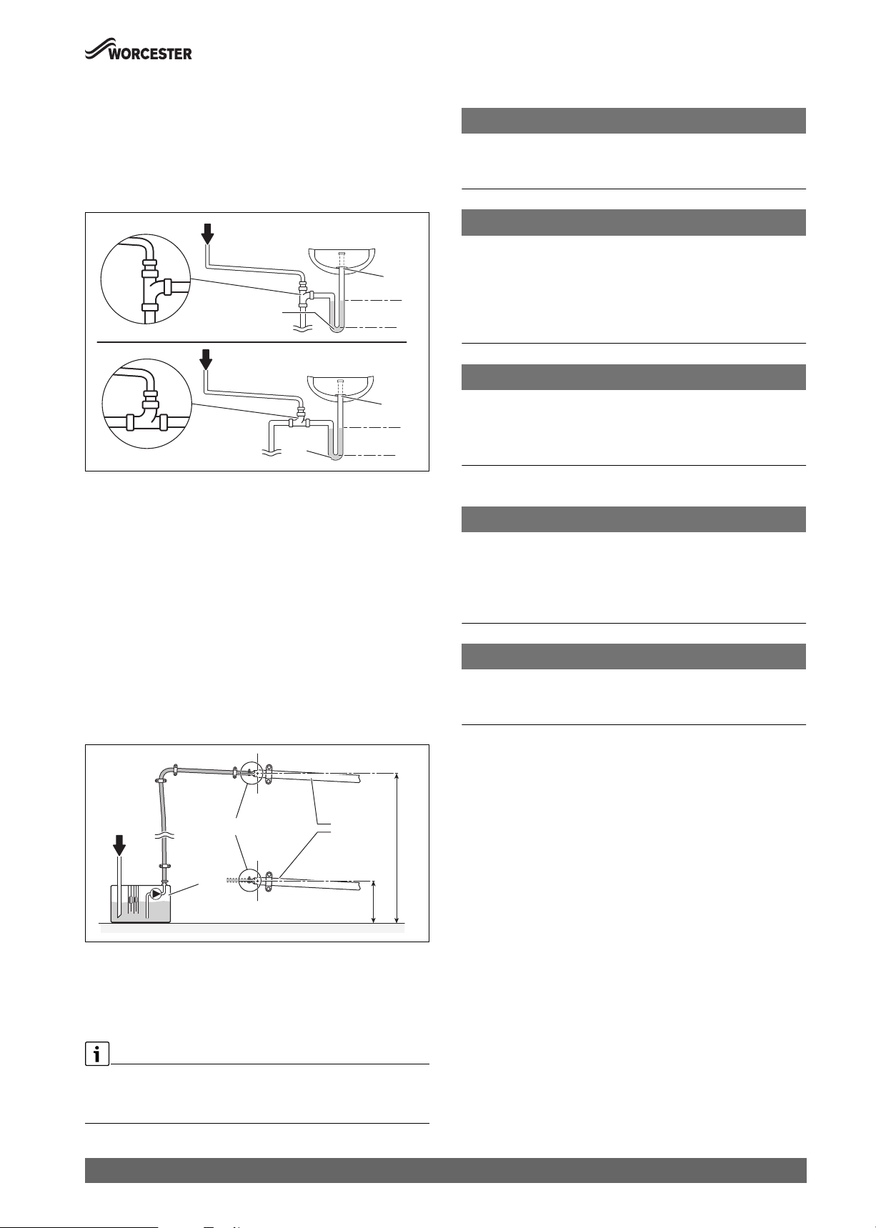
Pre-Installation
Waste pipe connection
Figure 30
Alternatively if the first option is not possible an internal kitchen,
bathroom or washing machine waste pipe etc. can be used.
Ensure that the condensate drain pipe is connected “down stream” of
the waste trap and that the condensate drain enters into the top of the
pipe using a swept tee.
1
5
6
75mm
min.
1
5
75mm
Max.
C
min.
0010012767-001
6
Fig. 30 Waste pipe disposal
[1] Condensate discharge from appliance
[5] Visible air break at plug hole
[6] 75mm sink waste trap
Condensate pump
Figure 31
Where direct connection to a “gravity discharge” pipe work is not
physically possible, or where very long internal runs would be required to
reach a suitable discharge point, condensate should be removed using a
proprietary condensate pump, of a specification recommended by the
condensate pump manufacturer.
• The pump outlet should discharge to a suitable “gravity discharge”
outlet.
– The condensate then flows, by gravity, through the 22mm plastic
pipe to the condensate discharge point.
8
1
7
Fig. 31 Condensate pump example
[1] Condensate discharge from appliance
[7] Condensate pump
[8] Pipe work transition
[C] Gravity discharge pipe work
Proprietary condensate pump
▶ Ensure minimum and maximum pump lifting heights are followed as
per condensate pump manufacturers instructions.
Min.
0010023656-001
4.5.4 External connections
NOTICE:
Risk of condensate discharge freezing
▶ No external disposal of condensate unless the CondenseSure
siphon or a condensate pump is fitted.
NOTICE:
Rainwater down pipe or external drain disposal
Untreated condensate must not be allowed to flow into streams or rivers
▶ A rainwater down pipe or an external drain shall only be used for
condensate disposal if the down pipe or external drain is connected
to a combined foul and rainwater drainage system
▶ Refer to BS 6798 for more information on condensate disposal
NOTICE:
Grey water recovery system
Contamination of recovered water
▶ Condensate disposal shall not be allowed into a grey water recovery
system that is intended for re-use
External disposal considerations
NOTICE:
Freezing conditions
Frozen condensate will block the condensate drain pipe and stop the
appliance from running
▶ Pipe lengths should be kept to a minimum and the routed as vertically
as possible.
NOTICE:
Condensate waste disposal
▶ Care should be taken when siting a soak-away to avoid causing
damage to existing services and building footings.
If no other discharge method is possible then the use of an externally run
condensate drainage pipe terminating at a suitable foul water discharge
point, or purpose-designed soak away, may be considered. If this
method is chosen then the following measures should be adopted:
▶ A CondensSure external siphon accessory (part number:
7716192746) or third party condensate pump must be used.
▶ The external run be kept as short as possible and ideally should not
exceed three metres.
Additional precaution against freezing must be taken if the external
pipe run does exceed three metres.
▶ The pipe should be run internally as far as possible before going
externally and the pipe diameter should be increased to a minimum
internal diameter (ID) of 30mm before it passes through the wall to
the exterior. The pipe should be insulated externally using suitable
waterproof and weather resistant insulation.
▶ The hole through the wall for the condensate pipe should be sealed to
the building fabric on the internal and external face using a suitable
building material.
▶ The external pipe should take the shortest and least exposed route to
the discharge point, and should "fall" as steeply as possible away
from the appliance, with no horizontal runs in which condensate
might stand.
Worcester 2000 – 6 721 814 551 (2019/09)
25
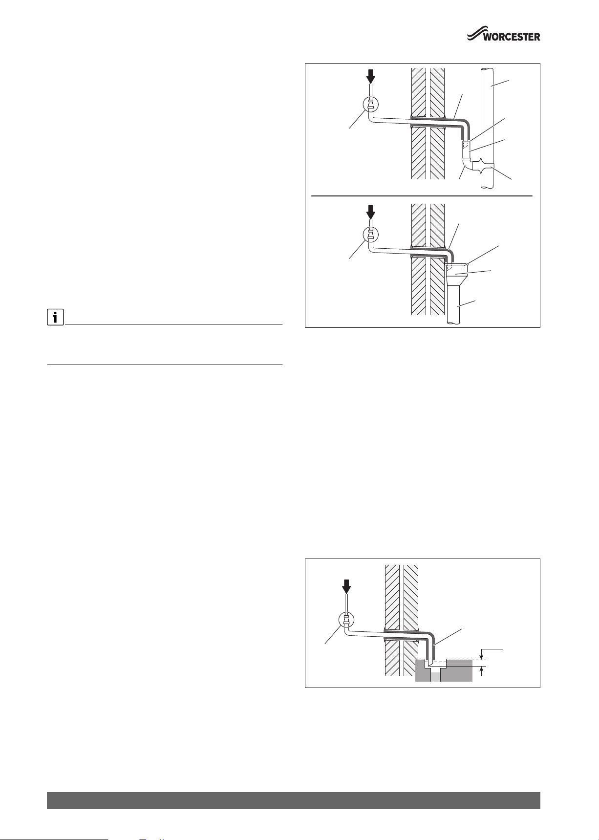
Pre-Installation
▶ The use of fittings, elbows etc. should be kept to a minimum and any
internal burrs on cut pipe work should be removed so that the internal
pipe section is as smooth as possible.
▶ All external pipe drainage will be improved if the end is cut at 45° as
opposed to a straight cut.
▶ In situations where there are likely to be extremes of temperature or
exposure, the use of a proprietary trace-heating system for external
pipe work, incorporating an external frost thermostat, should be
considered. All other guidance above and the instructions for the
trace heating system, should be closely followed.
▶ As well as trace heating, other methods for protecting pipe work that
are run externally should be considered to prevent freezing during
prolonged periods.
– Insulation materials can be used, these should be of class “O”
grade with an outer coating that is weather proof and have a UV
resistant finish. A minimum of 19mm thick insulation is
recommended for 32mm external pipes.
– The use of a drain cover (such as those to prevent leaf blockage)
may offer further protection from wind chill.
– An air break on the external pipe work can reduce the risk of the
appliance being inoperable due to the blocking and backing up of
the condensate.
1
10
9
11
8
14
12
13
1
9
20
8
12
10
Good Practice
▶ The following guidance indicates the good practices that must be
maintained for the Installation and Maintenance of a product.
Rain water down pipe with external air break
Figure 32
• Refer to following example to dispose of condensate to a rain water
down pipe.
• An air break or rain water hopper must be utilised, between the
appliance condensate outlet and the drainpipe, outside the property,
to avoid flooding of the appliance should the downpipe become
obstructed.
0010012784-002
Fig. 32 Disposal into rain water down pipe
[1] Condensate discharge from appliance
[8] Pipe work transition
[9] Insulate and increase pipe size
[10] External rain water pipe to foul water
[11] External air break
[12] Air gap
[13] Strap-on fitting
[14] 43mm 90° male/female bend
[20] Rain water hopper
Open drain or gully
Figure 33
Where the pipe terminates over an open drain or gully:
• Refer to following example to dispose of condensate to an open drain
or gully.
• The pipe should terminate below the grating level, but above water
level, in order to minimise “wind chill” at the open end.
• The use of a drain cover (such as those used to prevent blockage by
leaves) may offer further protection from wind chill.
1
26
8
Fig. 33 Disposal to open drain or gully
[1] Condensate discharge from appliance
[8] Pipe work transition
[9] Insulate and increase pipe size
Worcester 2000 – 6 721 814 551 (2019/09)
9
25mm min.
0010023655-002
 Loading...