


Worcester Greenstar HIU E
Table of contents
 Loading...
Bosch Worcester Greenstar HIU E, Worcester Greenstar HIU, Worcester Greenstar HIU E Plus, Worcester Greenstar HIU KE Plus Installation And Maintenance Instructions Manual
Installation and maintenance instructions
Heat Interface Unit
Greenstar HIU, HIU E, HIU E Plus & HIU KE Plus
6720808928-00.1Wo
For connection to a district heating system supplying heating and domestic hot water
6 720 808 928 (2017/06) UK & IE

Contents
Contents
1 Key to symbols and safety instructions . . . . . . . . . . . . . . . . . . . 4
1.1 Key to symbols . . . . . . . . . . . . . . . . . . . . . . . . . . . . . . . . . 4
1.2 General safety instructions . . . . . . . . . . . . . . . . . . . . . . . . 4
2 Appliance information . . . . . . . . . . . . . . . . . . . . . . . . . . . . . . . . . 6
2.1 General information . . . . . . . . . . . . . . . . . . . . . . . . . . . . . 6
2.2 Intended use . . . . . . . . . . . . . . . . . . . . . . . . . . . . . . . . . . . 7
2.3 Misuse . . . . . . . . . . . . . . . . . . . . . . . . . . . . . . . . . . . . . . . . 7
2.4 Declaration of conformity . . . . . . . . . . . . . . . . . . . . . . . . . 7
2.5 Type plate . . . . . . . . . . . . . . . . . . . . . . . . . . . . . . . . . . . . . 7
2.6 Standard delivery . . . . . . . . . . . . . . . . . . . . . . . . . . . . . . . 8
2.7 Appliance dimensions and hydraulic connections . . . . . 8
2.8 Internal layout . . . . . . . . . . . . . . . . . . . . . . . . . . . . . . . . . . 9
2.9 Electrical schematic . . . . . . . . . . . . . . . . . . . . . . . . . . . 10
2.10 Designation of components . . . . . . . . . . . . . . . . . . . . . 12
2.11 Appliance information . . . . . . . . . . . . . . . . . . . . . . . . . . 14
2.12 Function Schematic . . . . . . . . . . . . . . . . . . . . . . . . . . . 16
3 Regulations . . . . . . . . . . . . . . . . . . . . . . . . . . . . . . . . . . . . . . . . 17
3.1 General . . . . . . . . . . . . . . . . . . . . . . . . . . . . . . . . . . . . . 17
3.2 Standards and Guidelines . . . . . . . . . . . . . . . . . . . . . . . 17
3.3 Inspection and maintenance . . . . . . . . . . . . . . . . . . . . 17
4 Pre-installation requirements . . . . . . . . . . . . . . . . . . . . . . . . . 17
4.1 General . . . . . . . . . . . . . . . . . . . . . . . . . . . . . . . . . . . . . 17
4.2 System preparation . . . . . . . . . . . . . . . . . . . . . . . . . . . . 17
4.3 Domestic water supply . . . . . . . . . . . . . . . . . . . . . . . . . 18
4.4 Pressure relief pipe work . . . . . . . . . . . . . . . . . . . . . . . 18
4.5 Cleaning primary system . . . . . . . . . . . . . . . . . . . . . . . 19
4.6 Appliance locations and clearances . . . . . . . . . . . . . . . 19
4.6.1 Location . . . . . . . . . . . . . . . . . . . . . . . . . . . . . . . . . . . . . 19
4.6.2 Rooms containing a bath or a shower . . . . . . . . . . . . . 19
4.6.3 Installation and maintenance Clearances . . . . . . . . . . 19
4.6.4 Compartment clearances . . . . . . . . . . . . . . . . . . . . . . . 20
4.7 Example layouts . . . . . . . . . . . . . . . . . . . . . . . . . . . . . . 20
4.7.1 Unmixed central heating with radiators . . . . . . . . . . . . 20
4.7.2 Unmixed central heating with under-floor . . . . . . . . . . 21
4.8 Mounting frame . . . . . . . . . . . . . . . . . . . . . . . . . . . . . . . 22
5 Installation . . . . . . . . . . . . . . . . . . . . . . . . . . . . . . . . . . . . . . . . . 22
5.1 Support bracket and mounting frame fitting . . . . . . . . 22
5.1.1 Wall mounting template . . . . . . . . . . . . . . . . . . . . . . . . 22
5.1.2 Fitting support bracket and mounting rail . . . . . . . . . . 23
5.1.3 Example pipe-work installation. . . . . . . . . . . . . . . . . . . 23
5.1.4 Fitting the filling link assembly . . . . . . . . . . . . . . . . . . . 23
5.1.5 Fitting an external filling link (not supplied with appliance)
. . . . . . . . . . . . . . . . . . . . . . . . . . . . . . . . . . . . . . . . . . . . . 24
5.1.6 Flushing valve accessory installation . . . . . . . . . . . . . . 24
5.1.7 Flow regulating valve (not supplied with appliance) . . 25
5.1.8 Hydraulic connections on mounting frame . . . . . . . . . 25
5.2 Hanging the appliance . . . . . . . . . . . . . . . . . . . . . . . . . . 25
5.3 Electrical . . . . . . . . . . . . . . . . . . . . . . . . . . . . . . . . . . . . 26
5.3.1 Pre wired mains cable . . . . . . . . . . . . . . . . . . . . . . . . . . 26
5.3.2 Installer connections . . . . . . . . . . . . . . . . . . . . . . . . . . . 27
5.3.3 Access to electrical connections: . . . . . . . . . . . . . . . . . 27
5.3.4 Cable retainer clamps . . . . . . . . . . . . . . . . . . . . . . . . . . . 28
5.4 Frost protection . . . . . . . . . . . . . . . . . . . . . . . . . . . . . . . 28
5.5 By-pass function . . . . . . . . . . . . . . . . . . . . . . . . . . . . . . . 29
5.6 Limit return temperature . . . . . . . . . . . . . . . . . . . . . . . . 29
6 Commissioning . . . . . . . . . . . . . . . . . . . . . . . . . . . . . . . . . . . . . . 30
6.1 Cleaning the primary circuit . . . . . . . . . . . . . . . . . . . . . . 30
6.2 Flushing kit accessory . . . . . . . . . . . . . . . . . . . . . . . . . . 30
6.3 Filling and venting the unit . . . . . . . . . . . . . . . . . . . . . . . 30
6.3.1 Integral keyless filling link . . . . . . . . . . . . . . . . . . . . . . . . 30
6.3.2 External filling link (not supplied with appliance) . . . . . 31
6.4 Control unit . . . . . . . . . . . . . . . . . . . . . . . . . . . . . . . . . . . 31
6.4.1 Control unit LED Indicators . . . . . . . . . . . . . . . . . . . . . . 31
6.4.2 Domestic hot water rotary switch . . . . . . . . . . . . . . . . . 32
6.4.3 Central heating rotary switch . . . . . . . . . . . . . . . . . . . . . 32
6.5 Control valve status indication . . . . . . . . . . . . . . . . . . . . 33
6.6 Central heating circulation pump . . . . . . . . . . . . . . . . . . 33
6.6.1 Pump key lock function . . . . . . . . . . . . . . . . . . . . . . . . . 33
6.6.2 Pump operational status and view pump curve setting 33
6.6.3 Available hydraulic pressure . . . . . . . . . . . . . . . . . . . . . 34
6.6.4 Central heating circulation pump Characteristics . . . . 34
6.6.5 Pump curve adjustment . . . . . . . . . . . . . . . . . . . . . . . . . 35
6.7 Sense II (EMS controller) configuration . . . . . . . . . . . . 35
6.7.1 Operating the service menu . . . . . . . . . . . . . . . . . . . . . . 35
6.7.2 Central heating settings - Outdoor temperature or Room
temperature compensated control . . . . . . . . . . . . . . . . 36
6.7.3 Heat Interface Unit settings . . . . . . . . . . . . . . . . . . . . . . 36
6.7.4 Electronic by-pass function setup . . . . . . . . . . . . . . . . . 36
6.7.5 Floor drying function . . . . . . . . . . . . . . . . . . . . . . . . . . . 37
6.8 Integral heat meter (if fitted) . . . . . . . . . . . . . . . . . . . . . 38
6.9 Water quality . . . . . . . . . . . . . . . . . . . . . . . . . . . . . . . . . . 40
6.9.1 Typical for District heating water . . . . . . . . . . . . . . . . . . 40
6.9.2 Domestic hot water for copper brazed plate heat
exchangers . . . . . . . . . . . . . . . . . . . . . . . . . . . . . . . . . . . 41
6.10 Domestic hot water performance chart . . . . . . . . . . . . . 42
6.11 Central heating performance charts . . . . . . . . . . . . . . . 44
6.11.1 15kW & 7.5kW . . . . . . . . . . . . . . . . . . . . . . . . . . . . . . . . 44
6.11.2 5kW & 3.5kW . . . . . . . . . . . . . . . . . . . . . . . . . . . . . . . . . 46
6.12 Testing . . . . . . . . . . . . . . . . . . . . . . . . . . . . . . . . . . . . . . . 47
6.13 Commissioning checklist . . . . . . . . . . . . . . . . . . . . . . . . 48
6.14 Fitting the cover . . . . . . . . . . . . . . . . . . . . . . . . . . . . . . . 50
6.15 Hand over . . . . . . . . . . . . . . . . . . . . . . . . . . . . . . . . . . . . 50
6.16 Appliance guarantee . . . . . . . . . . . . . . . . . . . . . . . . . . . . 50
6.16.1 Guarantee registration . . . . . . . . . . . . . . . . . . . . . . . . . . 50
7 Inspection and maintenance . . . . . . . . . . . . . . . . . . . . . . . . . . . 51
7.1 Cleaning the district filter . . . . . . . . . . . . . . . . . . . . . . . . 51
7.1.1 Removing the cover . . . . . . . . . . . . . . . . . . . . . . . . . . . . 51
7.1.2 Draining the appliance . . . . . . . . . . . . . . . . . . . . . . . . . . 51
7.1.3 Filter removal . . . . . . . . . . . . . . . . . . . . . . . . . . . . . . . . . 51
7.2 Inspection record . . . . . . . . . . . . . . . . . . . . . . . . . . . . . . 52
8 Replacement of parts . . . . . . . . . . . . . . . . . . . . . . . . . . . . . . . . . 54
8.1 Draining the appliance . . . . . . . . . . . . . . . . . . . . . . . . . . 54
8.2 Plate heat exchanger . . . . . . . . . . . . . . . . . . . . . . . . . . . 54
8.3 Control valves . . . . . . . . . . . . . . . . . . . . . . . . . . . . . . . . . 55
6 720 808 928 (2017/06)2

8.4 Differential pressure control valve . . . . . . . . . . . . . . . . 55
8.5 Circulating pump . . . . . . . . . . . . . . . . . . . . . . . . . . . . . . 55
8.6 Heat meter . . . . . . . . . . . . . . . . . . . . . . . . . . . . . . . . . . . 56
8.7 Expansion vessel . . . . . . . . . . . . . . . . . . . . . . . . . . . . . . 56
8.8 Domestic hot water NTC sensor and safety valve . . . . 56
8.9 Flow turbine, flow regulator assembly and filter . . . . . 57
8.10 Summer by-pass (if fitted) . . . . . . . . . . . . . . . . . . . . . . 57
8.11 District and central heating NTC sensors . . . . . . . . . . . 57
8.12 Control unit . . . . . . . . . . . . . . . . . . . . . . . . . . . . . . . . . . 58
9 Fault finding and diagnostics . . . . . . . . . . . . . . . . . . . . . . . . . . 59
9.1 Central heating trouble shooting guide . . . . . . . . . . . . 59
9.2 Domestic hot water trouble shooting guide . . . . . . . . . 60
9.3 HIU Control unit LED indications . . . . . . . . . . . . . . . . . 61
9.4 Control valve fault indication . . . . . . . . . . . . . . . . . . . . 62
9.4.1 Action of control valve during an error . . . . . . . . . . . . . 62
9.4.2 Control valve calibration . . . . . . . . . . . . . . . . . . . . . . . . 62
9.5 Circulating pump fault indication . . . . . . . . . . . . . . . . . 62
9.6 Sense II (EMS controller) Diagnosis menu . . . . . . . . . . 63
9.6.1 Operating the service menu . . . . . . . . . . . . . . . . . . . . . 63
9.6.2 Heat Interface Unit diagnosis menu . . . . . . . . . . . . . . . 63
9.6.3 Heat Interface Unit diagnosis functions . . . . . . . . . . . . 63
9.6.4 Heat Interface Unit function test menu . . . . . . . . . . . . . 64
9.7 Central heating pump test . . . . . . . . . . . . . . . . . . . . . . . 64
9.8 Heat meter (if fitted) . . . . . . . . . . . . . . . . . . . . . . . . . . . 64
9.9 Component resistance characteristics . . . . . . . . . . . . . 64
9.9.1 Flow/return temperature NTC sensors . . . . . . . . . . . . . 64
9.9.2 DHW NTC wet sensor . . . . . . . . . . . . . . . . . . . . . . . . . . . 64
9.9.3 Outdoor weather compensation sensor . . . . . . . . . . . . 64
Contents
6 720 808 928 (2017/06) 3
Key to symbols and safety instructions
1
1 Key to symbols and safety instructions
1.1 Key to symbols
Warnings
List entries, first and second levels
• A single component/item
• A component/list, made up of multiple parts/items.
– Sub component or sublist of main component/list.
–etc.
Warnings in this document are identified by a warning
triangle printed against a grey background.
Keywords at the start of a warning indicate the type and
seriousness of the ensuing risk if measures to prevent
the risk are not taken.
The following keywords are defined and can be used in this document:
• NOTICE indicates a situation that could result in damage to property
or equipment.
• CAUTION indicates a situation that could result in minor to medium
injury.
• WARNING indicates a situation that could result in severe injury or
death.
• DANGER indicates a situation that will result in severe injury or
death.
Important information
This symbol indicates important information where
there is no risk to people or property.
Additional symbols
Symbol Meaning
a numbered step in an action sequence
a step in an action sequence
a reference to a related part in the document or to other
related documents
a reference number to identify or refer to a part or item
a list entry
a list entry (second level)
Table 1 Symbols
Examples of additional symbols used
A numbered step in an action sequence
A sequence of numbered steps or actions carried out in a specific order
to complete a task.
1. First action
2. Second action
3. Third action
etc.
A step in an action sequence
A sequence of defined actions or steps carried out in order to complete
a task.
▶Action
▶Next action
▶etc
A reference to a related part in the document or to other related
documents.
To refer the reader to a specific figure/table/section within the manual.
e.g. figure 1.
A reference number to identify or refer to a part or item.
In a related figure, items or parts identified by a sequential number.
1.2 General safety instructions
Follow these guidelines
▶ Country-specific regulations and standards must be observed when
installing the appliance.
▶ The local regulations and requirements for the electrical connection
of the power supply.
▶ The regulations and standards relating to the safety equipment of the
heating system.
▶ Read any installation instructions (Heat interface unit, heating
controls, etc.) carefully before starting the installation.
▶ Observe the safety instructions and warnings.
▶ Observe national and regional regulations, technical rules and
guidelines.
▶ Record all work carried out.
Risk of electrical shock
▶ Any electrical work or maintenance must only be carried out by
qualified/registered person.
▶ Before carrying out any work on electrical components, isolate them
from the power supply (230 V AC) (fuse, circuit breaker) and secure
against unintentional reconnection.
Appliance operation
This appliance can be used by children aged from 8 years
and above and persons with reduced physical, sensory or
mental capabilities or lack of experience and knowledge, if
they have been given supervision or instruction concerning
the use of the appliance, in a safe way, and understand the
hazards involved.
Children shall not play with the appliance.
Cleaning and user maintenance shall not be made by
children without supervision.
Important handling instructions
Care should be taken when transporting, lifting and carrying the
appliance.
▶ Use a means of transport suitable for handling appliances (e.g. sack
truck with strap, stair climbing or step trolley).
▶ When handling appliances, secure them against a fall.
▶ Let only trained personnel undertake the handling.
▶ The correct method for handling heavy objects should be strictly
observed, at all times.
General handling guidelines
▶ Only remove packaging at the time of the final installation.
▶ Never lift or carry the appliance on your own.
▶ Never lift or carry packages by the shipping straps.
▶ During handling and unpacking, wear safety gloves to prevent
injuries to your hands through sharp-edged appliance components.
▶ Dispose of packaging materials appropriately.
6 720 808 928 (2017/06)4
Key to symbols and safety instructions
Packaging
The following points should be observed during unpacking:
• Check the delivery immediately upon receipt for completeness and
transport damage
• In the event of transport damage, the delivery should only be
accepted conditionally
• Do not use damaged components for assembly
• The first fix rail can be removed from the side of the carton via a
perforated flap so that it can be fitted without having to remove the
rest of the appliance and cover from the packaging. This will reduce
the risk of damage to the rest of the appliance whilst the system is
being commissioned. The remainder of the appliance will remain in
the packaging and can be stored safely until needed.
• Carefully unpack the unit
• Ensure that all packaging material is removed and the unit is free from
all materials that may prevent the unit from operating correctly
Siting and installation
Correct siting, assembly and installation of the individual components
are the fundamental requirements for safe and economical operation of
the appliance.
▶ Only trained contractors are to site and install the appliance and its
components.
▶ The appliance must only be installed in rooms and locations that
meet the manufactures requirements.
Commissioning
▶ The appliance and the components must only be commissioned by a
competent person.
▶ Check all connections for leakages prior to starting up the heating
system.
▶ All fixings and fittings must be checked and tightened if required after
the unit has been installed.
Risk of damage due to operator error
Operator errors can result in injury and damage to property.
▶ Ensure that only personnel who can operate this appliance correctly
have access to it.
Inspection, maintenance and repairs
▶ Inspection, maintenance and repairs must only be carried out by
competent persons.
▶ Use only original spare parts from the manufacturer. The
manufacturer can assume no liability for damage caused by spare
parts not supplied by the manufacturer.
Electrical work
Electrical work must only be carried out by a qualified electrician:
▶ Before starting electrical work;
– Ensure that the electricity supply is safely isolated and secure to
prevent inadvertent re-connection.
– Information on safe isolation can be found in the Health and
Safety Executive Guidance HSG85.
– Using test equipment approved to GS38 confirm that the
electricity supply is disconnected.
▶ Refer to the manufacturer’s information when installing other
components with Worcester equipment within the system.
Heat Exchanger
The unit contains copper-brazed stainless steel heat exchangers.
Please ensure the system complies with the requirements in
BS EN 12502 Part 1 and 2 to avoid any damage caused by corrosion.
Danger of burns and scalds
▶ Surfaces of individual components, connections and leaking water
can be very hot and cause severe burns and scalds.
▶ Do not touch hot surfaces.
▶ Caution should be taken not to touch any leaking water or drained
system water unless the temperature is known and safe.
Leakage
If leaks are observed:
▶ Immediately close all isolation valves.
▶ Ensure all leaks are repaired by a suitably qualified professional.
CAUTION: The district heating side of the appliance can
be operated with high pressure and high temperature
systems.
▶ Please apply extreme caution and wear the
appropriate safety equipment (PPE) when working
on suspected leaks.
NOTICE: The pressure differential across the primary
circuit of the heat interface unit must not exceed 80kPa
(800mbar) on units without a DPCV (differential
pressure control valve) as standard.
For units with internal DPCV (differential pressure
control valve) fitted, the maximum differential pressure
is 400kPa (4000mbar).
▶ A suitable means of control should be installed to
limit the differential pressure if the system design is
expected to exceed the limits above (depending on
the HIU model).
Instructing the customer
When handing over, instruct the user how to operate the heating system
and inform them about its operating conditions.
▶ Explain how to operate the heating system and draw the user's
attention to any safety-relevant action.
▶ Explain that modifications and repairs must only be carried out by an
authorised contractor.
▶ Hand customers the appliance documentation for safekeeping.
6 720 808 928 (2017/06) 5
Appliance information
2 Appliance information
2.1 General information
Model matrix
2)
1)
Model
Heat meter
Differential pressure control valve
Summer by-pass
Keyless filling link assembly
Flushing valve
Vertical pipe kit
Heat meter adaptor kit
Domestic hot water output (KW)
Domestic hot water flow rate (l/m)
Flow regulator colour
HIU KE Plus with heat meter Yes Yes Yes Yes Accessory Accessory No 58.6 21 Red 15
HIU KE Plus No Yes Yes Yes Accessory Accessory Accessory 58.6 21 Red 15
HIU E Plus with heat meter Yes Yes Yes Yes Accessory Accessory No 39.1 14 Pink 15
HIU E Plus No Yes Yes Yes Accessory Accessory Accessory 39.1 14 Pink 15
HIU E with heat meter Yes Yes Accessory Yes Accessory Accessory No 39.1 14 Pink 15
HIU E No Yes Accessory Yes Accessory Accessory Accessory 39.1 14 Pink 15
HIU with heat meter Yes Accessory Accessory Yes Accessory Accessory No 39.1 14 Pink 15
HIU No Accessory Accessory Yes Accessory Accessory Accessory 39.1 14 Pink 15
Table 2 Model matrix
1) Domestic hot water output values are for a temperature rise of 40K.
2) Domestic how water flow rate values are for a temperature rise of 40K.
Main Features
• Easy to install with minimal installation space required.
• Internally insulated to minimise heat loss.
• Provides domestic hot water and central heating to properties.
• Hydraulic system separation with two heat exchangers.
• Domestic hot water demands take priority over central heating demands.
• The domestic hot water plate heat exchanger temperature is optimised to reduce the risk of lime scale formation.
• The electronic control unit provides fully modulated central heating and domestic hot water temperature control.
• Temperature controlled primary heating flow, via a by-pass valve, ensures heat is immediately available when domestic hot water is required.
• Low return temperature in the primary circuit maximises efficiency of the system.
• The appliance can be supplied with or without a heat meter fitted.
• Installation pipe work can be routed down behind the back of the HIU.
– Pre-plumbing kit available
Central heating output (kW)
6 720 808 928 (2017/06)6
Appliance information
6720808928-46.1Wo
2
0086
1
6720810422-03.1Wo
1
2.2 Intended use
The appliance provides domestic hot water and central heating to
properties that are serviced from district heating or central boiler plants.
The appliance consists of two heat exchangers, one for the domestic hot
water providing instant hot water at a safe regulated temperature and
the second for central heating. The appliance is indirect so the primary
heating circuit is hydraulically separated from the property central
heating by the second plate heat exchanger. Domestic hot water takes
priority over the central heating demand.
This appliance must only be used as a source of heating and hot water in
a sealed system.
Refer to the details on the type plate and the specifications to ensure
correct use of this appliance.
2.3 Misuse
Appliance must be used as per the intended use statement. Operation
outside the parameters of the intended use is considered misuse and
could cause harm to people and damage to property.
Using the appliance outside of its intended use may also invalidate the
manufacturer's guarantee.
2.4 Declaration of conformity
This product, in design and operation, conforms to the European
Directives and supplementary national requirements.
Compliance is demonstrated by the CE marking.
You can request the declaration of conformity for the product. To do so,
send your request to the address on the back of the manual.
The appliance is tested to the relevant clauses of the following
standards: EN60335,EN62233,EN55014 and EN61000.
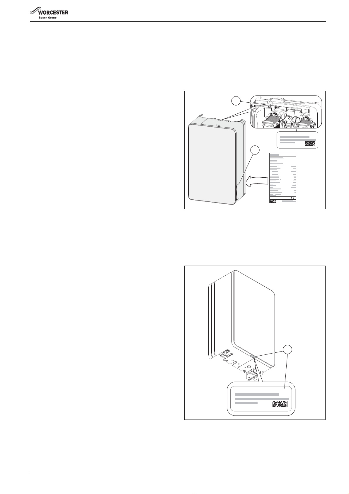
2.5 Type plate
Refer to figure 1
The type plate contains information on device performance, the
registration data and the serial number. This is located inside the
appliance cover [2].
There is an addition data label [1] which also has the registration data
and the serial number. This is located on the back plate behind the
control unit.
Fig. 1 Type plate location
Customer identification of the appliance
Refer to figure 2
The customer can easily identify the appliance as there is also a
additional data label [1.] This contains information of the appliance
model and serial number and is located on the bottom centre of the
cover panel.
Fig. 2 Customer data label
6 720 808 928 (2017/06) 7
Appliance information
6720808928-03.1Wo
263
1 2 3 4 5 6
7
440
270
390
18
19
18
65 65 65 65 65
40
127 50
79
700
582
37
81
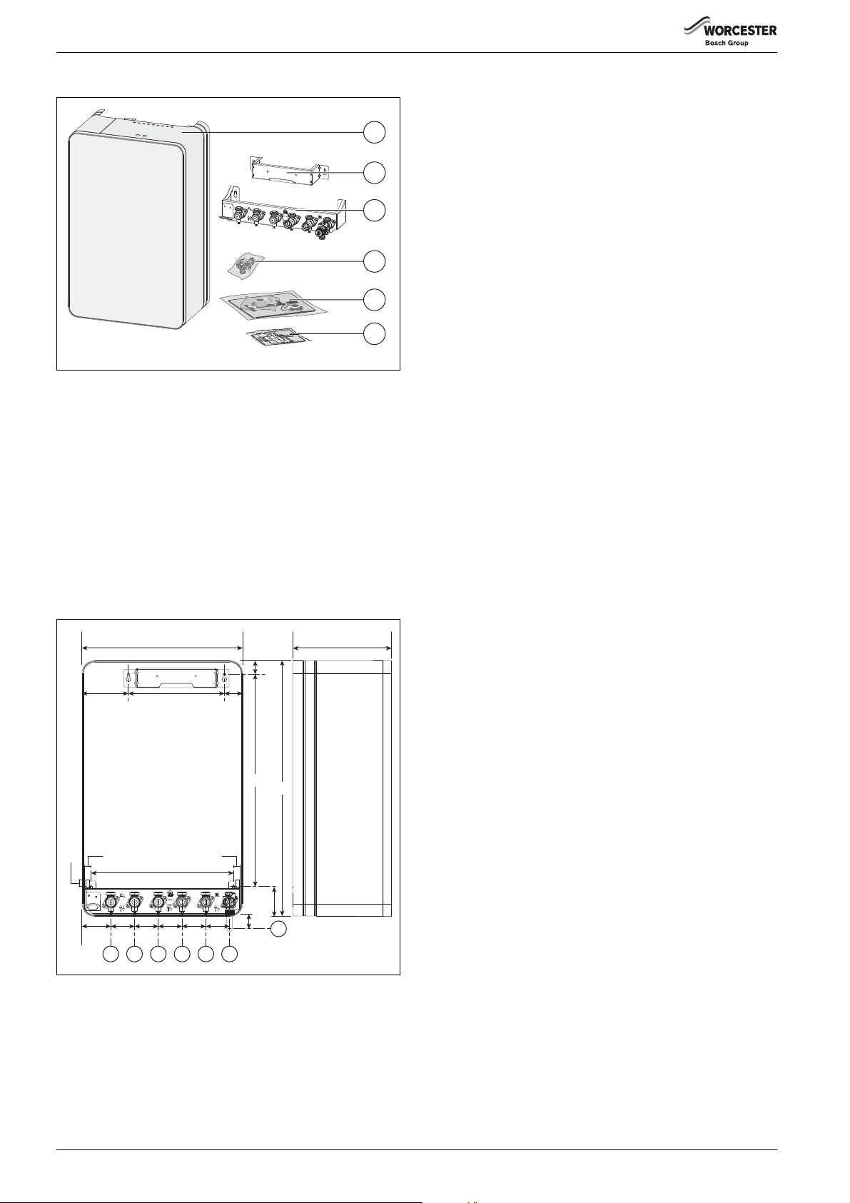
2.6 Standard delivery
Fig. 3 Standard package contents
[1] Heat Interface Unit
[2] Support bracket
[3] Mounting frame
[4] Filling link assembly
[5] Fittings and literature pack:
- Installation and Maintenance Instructions
- User Instructions
- Wall mounting template
- Sealing pack
- Compression fittings
- Pressure Relief Valve installer connection elbow
[6] Pre-payment scheme kit
1
2
3
4
5
6
6720808928-07.1Wo
2.7 Appliance dimensions and hydraulic connections
Fig. 4 Casing dimensions and hydraulic connections
[1] Cold mains inlet (22mm)
[2] Domestic Hot Water outlet (22mm)
[3] District heating supply (22mm)
[4] District heating return (22mm)
[5] Central heating flow (22mm)
[6] Central heating return (22mm)
[7] Pressure relief valve (15mm)
6 720 808 928 (2017/06)8
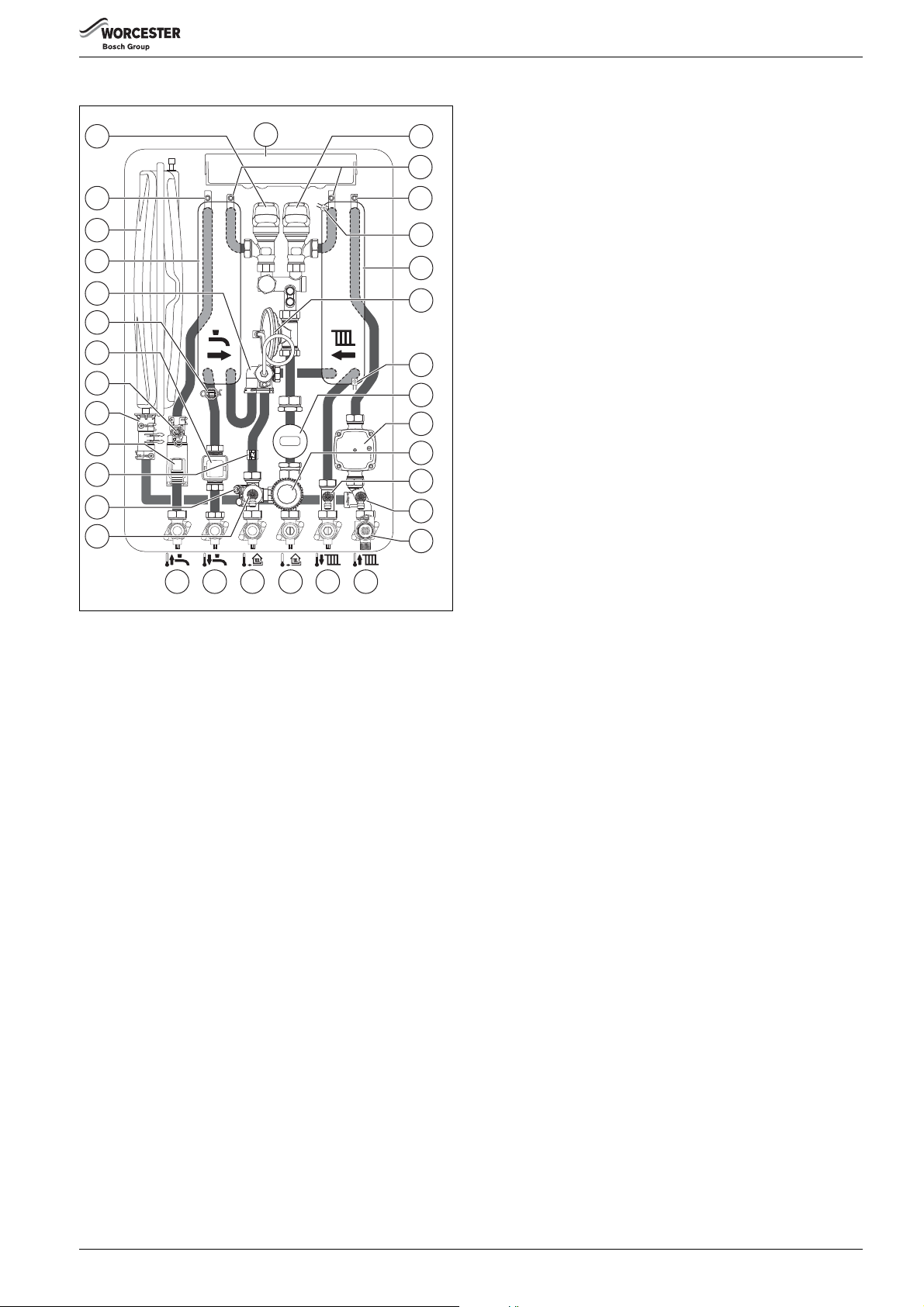
2.8 Internal layout
1
2
33
32
31
30
29
28
27
26
25
24
23
22
21
20 19 18
Fig. 5 Example HIU KE Plus with heat meter
17 16
3
4
5
6
7
8
9
10
11
12
13
14
15
Appliance information
[1] Domestic Hot Water control valve
[2] Control unit
[3] Central heating control valve
[4] Manual air vent (district heating)
[5] Manual air vent (central heating)
[6] Return sensor NTC (district heating)
[7] Plate heat exchanger (central heating)
[8] Differential pressure control valve (if fitted, Table 2, Model
matrix for standard component or accessory)
[9] Flow sensor NTC (central heating)
[10] Heat meter (if fitted, Table 2, Model matrix for standard
component or accessory)
[11] Central heating circulating pump
[12] By-pass valve (if fitted, Table 2, Model matrix for standard
component or accessory)
[13] Drain point (central heating flow)
[14] Drain point (central heating return)
[15] Pressure relief valve (central heating)
[16] Central heating return connection
[17] Central heating flow connection
[18] District heating return connection
[19] District heating supply connection
[20] Domestic Hot Water outlet connection
[21] Cold mains inlet connection
[22] Filter and drain point (district heating)
[23] Heat meter flow sensor connection point
[24] Supply sensor NTC (district heating)
[25] Flow turbine and flow regulator
[26] Expansion vessel connection point
6720808928-01.2Wo
[27] Domestic Hot Water pressure relief valve
[28] Domestic Hot Water safety valve
[29] Domestic Hot Water outlet sensor NTC
[30] Manifold (district heating)
[31] Plate heat exchanger (Domestic Hot Water)
[32] Expansion vessel
[33] Manual air vent (Domestic Hot Water)
6 720 808 928 (2017/06) 9

Appliance information
6720808928-14.1Wo
2
18
17
16
11
12
15 14
13
10
6
7
4
3
5
1
9
8
1
5
3
2
4
M
LR
L
120/230 VAC
PW2PW1
N
14 N
14 N
2.9 Electrical schematic
Fig. 6 Electrical schematic
[1] Control unit
[2] Low voltage connections (rear in service position)
[3] 230V connections (rear in service position)
[4] Low voltage connections (front in service position)
[5] 230V connections (front in service position)
[6] Sense II connection
[7] Outdoor weather sensor
[8] 230V external control system
[9] Limiter connection (pre-wired link) remove link to connect limit
thermostat (for under-floor heating circuit protection)
[10] Mains 230V supply
[11] Circulating pump
[12] Flow sensor NTC (central heating)
[13] Return sensor NTC (district heating)
[14] Central heating control valve
[15] Domestic Hot Water control valve
[16] Supply sensor NTC (district heating)
[17] Domestic Hot Water outlet sensor NTC
[18] Flow turbine
[M] Provision for heat meter M-Bus connection
6 720 808 928 (2017/06)10

Control unit connections
63 N
4321
21
4321
4321
21
21
21
21
BUS
EMS
21
21
PW1
14 N
21
Component connections Installer connections
Connections/
Symbol
Function
Circulation pump
• Live output [Brown]
• Neutral output [Blue]
• Earth output [Green/Yellow]
Flow turbine connection
• Red [4]
•-
• Yellow [2]
• Black [1]
Flow sensor NTC (district heating)
• White [2]
• White [1]
Connections/
Symbol
LR L
230V
OUT
LN
230V
IN
LN
Function
Limiter thermostat (under-floor safety cut-off)
•Potential free
230 V feed to external controls modules
• Live output [L]
• Neutral output [N]
• Earth output [ ]
230 V supply to the appliance
• Live input [L]
• Neutral input [N]
• Earth input [ ]
Not used
Domestic Hot Water sensor NTC
• Blue [2]
21
• Blue [1]
Central heating control valve
Sense II connection
• Not polarity sensitive
• Brown [4]
• Black [3]
• White [2]
• Yellow [1]
Outdoor temperature sensor
• Not polarity sensitive
Domestic Hot Water control valve
• Blue [4]
• Green [3]
• Grey [2]
• Red [1]
Flow sensor NTC (central heating)
• Yellow [2]
• Yellow [1]
Return sensor NTC (district heating)
• Green [2]
• Green [1]
LR
14 N
120/230 VAC
L
PW2
N
Not used
230 V feed to external time and temperature
control
• Switch live demand input [LR]
• Live output [L]
• Neutral output [N]
• Earth output [ ]
Not used
Not used
Appliance information
Not used
Control panel fuse
Table 4
Table 3
6 720 808 928 (2017/06) 11

Appliance information
6720808928-02.2Wo
1
2
7
3
6
5
4
3
8
9
39
38
10
11
13
14
32
31
27
28
15
12
16
17
19
18
20
22
23
30
29
25
24
26
21
36
37
35
33
34
2.10 Designation of components
Fig. 7 Designation of components
6 720 808 928 (2017/06)12

Legend to Figure 7, Designation of components:
[1] Control unit
[2] Manual air vent (Domestic Hot Water)
[3] Manual air vent (district heating)
[4] Domestic Hot Water control valve
[5] Central heating control valve
[6] Return sensor NTC (district heating)
[7] Manual air vent (central heating)
[8] Plate heat exchanger (central heating)
[9] Flow sensor NTC (central heating)
[10] Circulating pump
[11] Drain point (central heating return)
[12] Central heating return connection
[13] Pressure relief valve (central heating)
[14] Pressure relief valve installer connection elbow
[15] Central heating flow connection
[16] Keyless filling link assembly
[17] District heating return connection
[18] Summer by-pass valve ( Table 2, Model matrix for standard component or accessory)
[19] District heating supply
[20] Filter and drain point (district heating)
[21] Heat meter flow sensor point
[22] Domestic Hot Water outlet
[23] Supply sensor NTC (district heating)
[24] Cold mains inlet
[25] Optional position for pressure gauge (pressure gauge can be moved from position [28] here)
[26] Domestic Hot Water safety valve
[27] Domestic flow turbine and flow regulator
[28] Pressure gauge
[29] Domestic Hot Water outlet sensor NTC
[30] Expansion vessel connector
[31] Domestic pressure relief valve
[32] Differential pressure control valve capillary connection onto manifold
[33] Manifold (district heating)
[34] Differential pressure control valve ( Table 2, Model matrix for standard component or accessory)
[35] Plate heat exchanger (Domestic Hot Water)
[36] Expansion vessel (Schrader valve located top, right hand side towards the back)
[37] Schrader valve access point
[38] Heat meter display (part of heat meter accessory), ( Table 2, Model matrix for standard component or accessory)
[39] Heat meter sensor (part of heat meter accessory), ( Table 2, Model matrix for standard component or accessory)
Appliance information
6 720 808 928 (2017/06) 13
Appliance information
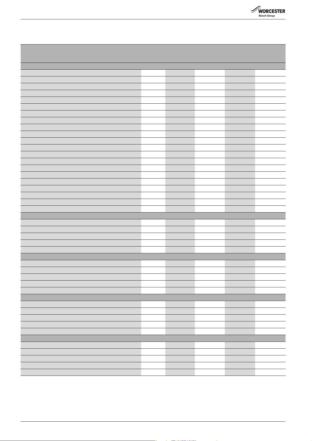
2.11 Appliance information
Technical data
HIU KE plus
with heat
Description Units HIU KE plus
meter
HIU E Plus
General
Height mm 700 700 700 700
Width mm 440 440 440 440
Depth mm 270 270 270 270
Total unit weight (lift weight) kg 33 33 31 31
Packaged unit weight kg 36 36 34 34
Minimum inlet pressure to achieve nominal DHW flow rate bar 2.0 2.0 1.5 1.5
Nominal output to domestic hot water
1)
kW 58.6 58.6 39.1 39.1
Output range to central heating kW 1.5 - 15 1.5 - 15 1.5 - 15 1.5 - 15
Maximum flow temperature secondary heating °C 80 80 80 80
Maximum flow temperature DHW °C 60 60 60 60
District heating flow and return connections (compression) mm 22 22 22 22
Secondary heating flow and return connections (compression) mm 22 22 22 22
Cold feed and DHW connections (compression) mm 15 15 15 15
Pressure relief valve connection mm 15 15 15 15
Maximum district limited flow rate with integrated DPCV l/s 0.38 0.38 0.355 0.355
Maximum working pressure district heating side bar 10 10 10 10
Pressure relief valve setting secondary heating side bar 3333
Maximum working pressure domestic hot water side bar 10 10 10 10
pH value (district water supply), approximate 7-9 7-9 7-9 7-9
Expansion vessel l 55 55
Expansion vessel charge bar 0.75 0.75 0.75 0.75
District Temperature (80°C)
Primary flow rate l/s 0.24 0.24 0.16 0.16
Primary return temperature °C 21.1 21.1 22.2 22.2
Primary pressure drop kPa 41.3 56.4 19.9 26.8
DHW output (50°C @ 40K rise) kW 58.6 58.6 39.1 39.1
DHW flow rate (50°C @ 40K rise) l/min 21 21 14 14
District Temperature (70°C)
Primary flow rate l/s 0.25 0.25 0.17 0.17
Primary return temperature °C 20.8 20.8 21.8 21.8
Primary pressure drop at 65/21 kPa 45.1 61.5 21.8 29.4
DHW output (45°C @ 35K rise) kW 51.3 51.3 34.2 34.2
DHW flow rate (45°C @ 35K rise) l/min 21 21 14 14
District Temperature (65°C)
Primary flow rate l/s 0.23 0.23 0.16 0.16
Primary return temperature °C 18.6 18.6 19.5 19.5
Primary pressure drop kPa 37.4 51.0 17.9 24.2
DHW output (40°C @ 30K rise) kW 44.0 44.0 29.3 29.3
DHW flow rate (40°C @ 30K rise) l/min 21 21 14 14
Electrical
Electrical power supply voltage AC...V 230 230 230 230
Frequency Hz 50 50 50 50
Maximum power consumption W 41.3 41.3 41.3 41.3
Standby power consumption W 3.1 3.1 3.1 3.1
Appliance protection rating IP X4D 40 X4D 40
Table 5
1) Nominal output to domestic hot water values are for a temperature rise of 40K.
HIU E Plus with
heat meter
6 720 808 928 (2017/06)14
Appliance information
Description Units HIU E
HIU E with
heat meter
HIU
HIU with heat
meter
General
Height mm 700 700 700 700
Width mm 440 440 440 440
Depth mm 270 270 270 270
Total unit weight (lift weight) kg 31 31 31 31
Packaged unit weight kg 34 34 34 34
Minimum inlet pressure to achieve nominal DHW flow rate bar 1.5 1.5 1.5 1.5
Nominal output to domestic hot water
1)
kW 39.1 39.1 39.1 39.1
Output range to central heating kW 1.5 - 15 1.5 - 15 1.5 - 15 1.5 - 15
Maximum flow temperature secondary heating °C 80 80 80 80
Maximum flow temperature DHW °C 60 60 60 60
District heating flow and return connections (compression) mm 22 22 22 22
Secondary heating flow and return connections (compression) mm 22 22 22 22
Cold feed and DHW connections (compression) mm 15 15 15 15
Pressure relief valve connection mm 15 15 15 15
Maximum district limited flow rate with integrated DPCV l/s 0.355 0.355 N/A N/A
Maximum working pressure district heating side bar 10 10 10 10
Pressure relief valve setting secondary heating side bar 3333
Maximum working pressure domestic hot water side bar 10 10 10 10
pH value (district water supply), approximate 7-9 7-9 7-9 7-9
Expansion vessel l 5555
Expansion vessel charge bar 0.75 0.75 0.75 0.75
District Temperature (80°C)
Primary flow rate l/s 0.16 0.16 0.16 0.16
Primary return temperature °C 22.2 22.2 22.2 22.2
Primary pressure drop kPa 19.9 26.8 12.1 19.1
DHW output (50°C @ 40K rise) kW 39.1 39.1 39.1 39.1
DHW flow rate (50°C @ 40K rise) l/min 14 14 14 14
District Temperature (70°C)
Primary flow rate l/s 0.17 0.17 0.17 0.17
Primary return temperature °C 21.8 21.8 21.8 21.8
Primary pressure drop kPa 21.8 29.4 13.3 20.9
DHW output (45°C @ 35K rise) kW 34.2 34.2 34.2 34.2
DHW flow rate (45°C @ 35K rise) l/min 14 14 14 14
District Temperature (65°C)
Primary flow rate l/s 0.16 0.16 0.16 0.16
Primary return temperature °C 19.5 19.5 19.5 19.5
Primary pressure drop kPa 17.9 24.2 11.0 17.3
DHW output (40°C @ 30K rise) kW 29.3 29.3 29.3 29.3
DHW flow rate (40°C @ 30K rise) l/min 14 14 14 14
Electrical
Electrical power supply voltage AC...V 230 230 230 230
Frequency Hz 50 50 50 50
Max. power consumption W 41.3 41.3 41.3 41.3
Standby power consumption W 3.1 3.1 3.1 3.1
Appliance protection rating IP X4D 40 X4D 40
Table 6
1) Nominal output to domestic hot water values are for a temperature rise of 40K.
6 720 808 928 (2017/06) 15
Appliance information
6720808928-18.1Wo
11
10
5
416
317
2
6
7
12
1
9
13
14
15
8
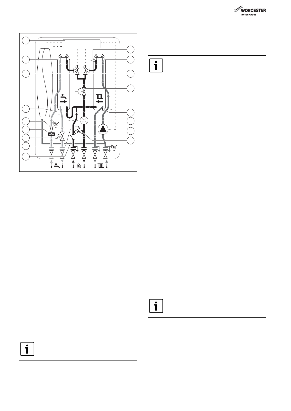
2.12 Function Schematic
Fig. 8 Function schematic
[1] Control unit
[2] Return sensor NTC (district heating)
[3] Central heating plate heat exchanger
[4] Central heating control valve
[5] Differential pressure control valve (if fitted)
[6] Flow sensor NTC (central heating)
[7] Heat meter (if fitted)
[8] Circulating pump
[9] Summer by-pass valve (if fitted)
[10] Heat meter flow sensor connection point
[11] Supply sensor NTC (district heating)
[12] Domestic Hot Water safety valve
[13] Flow turbine
[14] Flow regulator
[15] Domestic Hot Water outlet sensor NTC
[16] Domestic Hot Water control valve
[17] Domestic Hot Water plate heat exchanger
System description
If a summer by-pass valve [9] is fitted; in stand-by mode, the district
supply water flows from the district heating main, via the thermostatic
by-pass valve, therefore ensuring that hot water at 45 °C - 50 °C is
immediately available at the heat interface unit. This ensures a fast
warm-up of hot water at the tap, often referred to as keep hot function.
The above function is also available on a Sense II without the need for a
by-pass valve [9]. In this case, the domestic hot water control valve [16]
modulates to maintain 0 °C -60 °C at the primary water side of the heat
interface unit, depending on the temperature set for the by-pass
function in the controller settings menu.
The electronic control unit [1] provides fully modulated heating and hot
water control between maximum and minimum heat output. There are
two LEDs located on the top of the control unit [1] (visible through two
viewing holes in the top of the case). These indicate operating modes
and fault conditions.
Control unit LED indicators
▶ When an obstruction e.g. a shelf is positioned above
the unit it may be difficult to see the LED indicators.
If a hot water tap is opened, the flow turbine [13] is activated, the
central heating control valve [4] remains closed and the domestic hot
water control valve [16] modulates, allowing district supply water to
flow through the domestic hot water heat exchanger [18] to maintain
the pre-set hot water outlet temperature, which is measured using a NTC
sensor[15].
A domestic hot water safety shut-off valve [12] is provided in order to
interrupt the hot water flow to the tap in the event of excessive hot water
temperatures due to a failure condition. The domestic hot water outlet
temperature is adjustable between 30 °C - 60 °C on the heat interface
unit control unit [1].
During a central heating demand, the domestic hot water control valve
[16] remains closed and the central heating control valve [4]
modulates, allowing district water to flow through the central heating
heat exchanger [3] to maintain the pre-set central heating flow
temperature which is measured using a NTC sensor [6]. A low energy
self regulating pump [8] is used to provide water circulation through the
central heating circuit. The central heating flow temperature is
adjustable between 30 °C - 80 °C on the heat interface unit control [1].
The district heating return temperature is measured using a NTC sensor
[2].The control unit [1] will automatically modulate the central heating
delivery to ensure low return temperatures back to the district network.
The district return temperature will be kept below the central heating
flow temperature. This function prevents the HIU working in case the
district flow and return connections are reversed.
The default district heating return temperature limit is 50 °C, this can
only be adjusted with a Sense II.
If a Sense II is not used as a permanent device within the customers
property for controlling the system, it is possible to connect a Sense II to
the HIU control unit during commissioning only, in order to a set the
maximum allowable return temperature.
The heat interface unit can operate up to a supply differential pressure of
80kPa (800mbar). For supply differential pressures above 80kPa
(800mbar), a differential pressure control valve [5] should be fitted.
This provides a controlled differential pressure of 30kPa (300 mbar)
across the heat interface unit as the supply differential pressure varies
up to a maximum of 400kPa (4000mbar), the Worcester KE Plus, E Plus
and E HIU’s incorporate a DPCV as standard.
Worcester KE Plus with by-pass valve
▶ The maximum supply differential pressure is 400kPa
(4000mbar)
Electronic keep hot function
▶ This function will allow a small amount of district
water to flow through the heat meter.
6 720 808 928 (2017/06)16
Regulations
3Regulations
3.1 General
The special rules must be followed for buildings where the appliance is
installed.
The installation and maintenance of the unit must be performed by a
qualified person in accordance with regulations and rules of the local
area where installation is to take place.
3.2 Standards and Guidelines
Observe all rules, regulation, standard and guidelines
applicable to the installation and operation of the
appliance in your country.
When installing and operating, please refer to country-specific
regulations and standards, note in particular:
▶ The local standards and regulations on the installation conditions.
▶ The provision for the electrical connection to the power supply.
▶ The standards and regulations relating to the safety equipment of the
water heating system.
▶ The standards and regulations relating to the connection of drinking
water.
3.3 Inspection and maintenance
The heating system should be inspected regularly for the following
reasons:
• To achieve and maintain a high efficiency.
• To ensure operational safety.
The recommendation from BSRIA BG62/2015 is a maintenance check
every 3 years should be sufficient.
4.2 System preparation
Water system and pipe-work
• Any plastic pipe-work used on the central heating system must have
a polymeric oxygen barrier coating and at least 1000mm length of
copper or steel pipe connected to the appliance.
• Plastic pipe-work used for under-floor heating must be correctly
controlled and must not exceed the under-floor manufacturers’
specifications.
– With a single under-floor heating zone this may be able to be
controlled by the HIU provided the under-floor heating design
does not exceed the hydraulic capacity of the HIU internal
circulating pump, refer to section 6.6, Central heating circulation
pump.
• The district circuit is completely separated from the central heating
circuit by the use of a plate heat exchanger. However, in order to
protect the under-floor circuit in the event of a failure condition, a
limiter thermostat must be fitted onto the flow pipe to the under-floor
circuit and wired into the control unit ( figure 6). This switches off
the central heating pump in the event of an over temperature
condition.
• A single under-floor heating circuit can be controlled without the
need for an external mixing valve.
The switching point of the limiter thermostat, and if
fitted a thermostatic blending valve must be set at the
temperature set point + 10K for the under-floor heating
circuit.
The minimum flow temperature of the appliance is 30 °C.
NOTICE: Risk of system damage!
Damage to the system caused by a lack of, or insufficient
cleaning and servicing.
▶ Ensure that the heating system is inspected regularly
by an authorised heating engineer.
▶ Carry out any repairs immediately to avoid any
damage to the system.
4 Pre-installation requirements
4.1 General
NOTICE: Differential pressures above 80kPa
(800mbar) when no internal DPCV is fitted.
High differential pressure could affect the performance
of some components in the unit.
▶ Fit a differential pressure control valve to protect the
unit.
▶ The maximum allowable supply differential pressure
when the internal differential pressure control valve
is fitted is 400kPa (4000mbar).
It is recommended to insulate all service pipe work to the
heat interface unit in order to reduce heat losses and
improve system efficiency.
NOTICE: Under-floor heating circuits.
Damage caused by excessive flow temperature.
▶ Ensure the flow temperature does not exceed the
requirements of the under-floor heating circuit
manufacturer.
Secondary circuit/connections/valves
• All system connections, taps and mixing valves must be capable of
sustaining a pressure of 3 bar.
• Radiator valves should conform to local regulations.
• A thermostatic radiator valve (TRV) must be fitted to radiators in all
rooms except the room with the room thermostat. This must be fitted
with lock-shield valves and left open.
• Drain cocks are required at all the lowest points on the system.
• Air vents are required at all high points on the system.
6 720 808 928 (2017/06) 17
Pre-installation requirements
1
2
3
4
2
3
4
1
2
6720646608-123.1Wo
4.3 Domestic water supply
Use in hard water areas
Normally there is no need for water treatment to prevent scale formation
as the maximum temperature of the DHW heat exchanger is limited by
the electronic control.
In areas where temporary water hardness exceeds 200 ppm,
consideration may need to be given to the fitting of a scale prevention
device. In such circumstances, the advice of the local water authority
should be sought.
Showers/bidets:
• Ensure that the shower is suitable for use with mains water pressure.
• If a shower head can be immersed in water or comes closer than
25mm from the top edge of a bath or shower tray spill over level then
an anti-siphon device must be fitted to the shower hose.
• Bidets with direct hot and cold mains water can be used (with the
approval of the local water authority) and must be the over rim
flushing type with shrouded outlets to prevent the fitting of hand held
sprays.
Water mains pressure
• Minimum inlet pressure to achieve nominal DHW flow rate
– 58.6kW units - 2.0 bar
– 39.1kW units - 1.5 bar
• Maximum mains fed water pressure 10 bar.
– If necessary fit a pressure reducing valve.
• Where the mains water supply has a non-return, back flow
prevention valve fitted, a mini expansion vessel should be connected
to the mains water inlet pipe between the non-return valve and the
appliance.
NOTICE: Risk of damage to household appliances!
Non-return, back flow prevention devices (including
those associated with water meters) fitted to the mains
water supply can cause a pressure build up which could
damage the appliance and other household appliances.
▶ Fit a mini expansion between the non-return valve,
back flow prevention device.
4.4 Pressure relief pipe work
WARNING: Risk of scalding!
Injury if discharge pipe is not routed correctly.
▶ The pressure relief valve is a safety device for the
appliance and if activated may discharge boiling
water or steam through the relief valve drain pipe.
▶ Care should be taken when siting the outlet pipe so
that it does not cause an obstruction or discharge
above a window, entrance or other public access
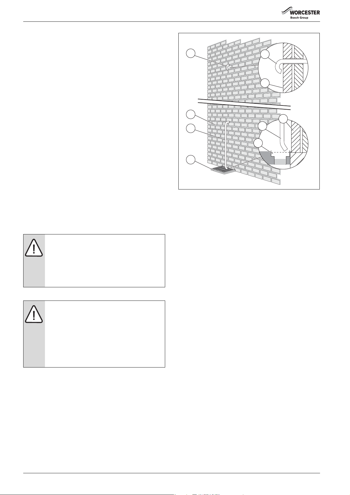
Refer to figure 9
• The pressure relief drain pipe [1] and [3] from the appliance should
be at least 15mm diameter copper pipe and run downwards to a safe
point of discharge, away from any electrical equipment or other
hazard, preferably to an external drain or soak away.
• Pipe [1] should be finished with a partial bend, near the outlet to face
the external wall (as shown) to help prevent freezing.
where it could cause a hazard.
Fig. 9 Pressure relief pipe-work external routing
[1] Outlet facing external wall
[2] External wall
[3] Outlet to external drain
[4] External drain
Internal PRV discharge
The PRV discharge pipe may terminate internally to a safe position such
as a waste pipe or soil pipe, provided that the following conditions are
met:
• The material used must be capable of taking the maximum
temperature provided by the District Heating primary flow.
• The discharge must be directly or indirectly visible and will not
discharge onto the occupants of the premises or onto any electrical
wiring or components. An example of "directly" is a tundish and
"indirectly" an audible indication of pressure loss.
• There is a continual fall towards the discharge point from the HIU.
• Where a tundish is used, a suitable trap is installed to protect against
foul smells entering into the living areas, whilst ensuring no undue
resistance to the discharge. An example would be a washing m achine
trap with upstand.
• For the higher district flow temperatures above 85 °C, It is
recommended to use the Hotun Hiflo tundish manufactured by RA
Tech UK. Guidance on this product can be found at http://
hutun.co.uk.
– We would also recommend that the Hotun Shield is used in
conjunction with the Hotun Hiflo on HIU installations. The Hotun
Hiflo tundish can also be used for providing a visual indicator
which will allow connection of a PRV directly into internal waste
pipes or soil stacks.
6 720 808 928 (2017/06)18
4.5 Cleaning primary system
6720646608-124.5Wo
2*
1
2
1
2
2
1
600mm
600mm
600mm
2250mm
2250mm
2*
†
†
†
6720808928-26.1Wo
NOTICE: Risk of damage to system or appliance!
Debris from the system can damage the appliance and
reduce efficiency. Failure to comply with the guidelines
for the use of water treatment with the appliance will
invalidate the appliance guarantee.
▶ Before installation, ensure that the central heating
system is cleaned and thoroughly flushed in
accordance to the standards and guidelines of the
country of installation.
4.6 Appliance locations and clearances
4.6.1 Location
• Follow local regulations for the location within the property that the
appliance is to be installed.
• This appliance is only suitable for installing internally within a
property at a suitable location onto a fixed rigid surface at least the
same size as the appliance and capable of supporting the appliance
weight.
• The appliance is not suitable for external installation.
No surface protection is required against heat transfer
from the appliance.
Pre-installation requirements
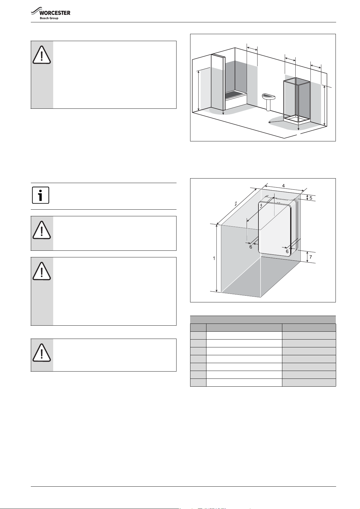
Fig. 10 Installations in rooms containing a bath or a shower
[2*] Without the end wall, zone 2 must extend 600mm from the bath.
[†] Radius 600mm.
4.6.3 Installation and maintenance Clearances
NOTICE: Appliance damage.
Damage caused by extreme temperatures.
▶ Ensure the ambient temperature is above 2 °C and
below 30 °C.
NOTICE: System damage.
Very cold t empera tures c an cause the heating system to
freeze, if there is a power failure or a fault in the system
the units frost protection function ( section 5.4
be compromised.
▶ Do not fit the appliance in areas with no heat
emitters, e.g. garage.
▶ Drain the central heating system if it is to be shut
down for an extended period.
4.6.2 Rooms containing a bath or a shower
NOTICE: Risk of electric shock
▶ Any switch or appliance control using mains
electricity must not be within reach of a person using
the bath or shower.
• In all cases the installation must be in accordance with the latest
amendments to the latest edition of the IET Wiring Regulations
(BS7671).
• The IP rating of the appliance.
– Units without internal heat meter, IPX4D.
The IP rating of the appliance allows it to be installed in, and
outside of, zone 2.
– Unit with internal heat meter, IP40.
The IP rating of the appliance dictates that it must be installed
outside of zone 2.
• Circuit breaking devices should be used in accordance with the
regulations.
• The diagram is for guidance only.
) will
Fig. 11 Minimum installation and maintenance clearances
Minimum Installation and Maintenance clearances
Description Dimensions (mm)
1 Overall clearance height 930
2 Overall clearance depth 870
3 In front of appliance 600
4 Overall clearance width 450
5 Above the appliance 30
6 Either side of appliance 5
7Below the appliance 200
6 720 808 928 (2017/06) 19
Pre-installation requirements
6720808928-39.1Wo
6720808928-47.1Wo
EMS
21
21
6720808928-49.1Wo
LR
L
120/230 VAC
N
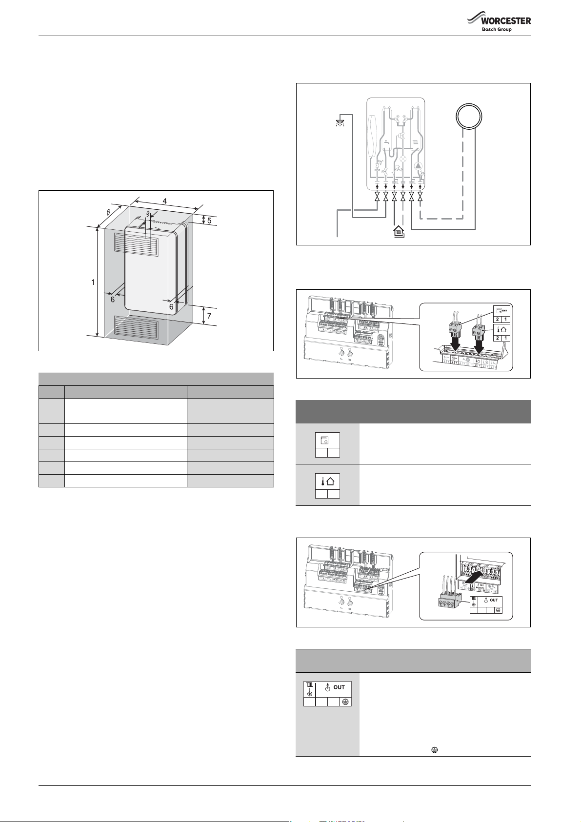
4.6.4 Compartment clearances
If the appliance is to be fitted in a compartment, the following minimum
clearances for the compartment dimensions apply. This is in addition to
the normal installation and servicing clearances.
• All service pipe work to the heat interface unit MUST be insulated
when installed within a ventilated compartment.
• If the ambient temperature within the compartment exceeds 30 °C
then it is recommended to make provision for ventilation.
– Ventilation openings must be provided at the front of the
compartment at the lower and upper positions. Each opening
must have a minimum size of 300mm by 80mm, 240cm
2
free
area.
4.7 Example layouts
4.7.1 Unmixed central heating with radiators
Fig. 13
Option 1: Control of radiator heating system with Sense II (EMS controller) example
Fig. 12 Minimum compartment clearances
Minimum Installation and Maintenance clearances
Description Dimensions (mm)
1 Compartment height 930
4 Compartment width 450
5 Above the appliance 30
6 Either side of appliance 5
7 Below the appliance 200
8 Compartment depth 290
9 Appliance to removable door 20
Fig. 14
Connections/
Symbol
Function
Sense II connection
• EMS2 Room control
– Not polarity sensitive
Outdoor temperature sensor
• Not polarity sensitive
Option 2: Control of radiator heating system with 230V programmable room thermostat example
Fig. 15
Connections/
Symbol
Function
230 V feed to external time and temperature
control
• 230V programmable room thermostat
LR
120/230 VAC
N
L
– Switch live demand input [LR]
– Live output [L]
– Neutral output [N]
– Earth output [ ]
6 720 808 928 (2017/06)20
Pre-installation requirements
6720808928-40.1Wo
T
LR L
21
6720808928-52.1Wo
LR
L
120/230 VAC
N
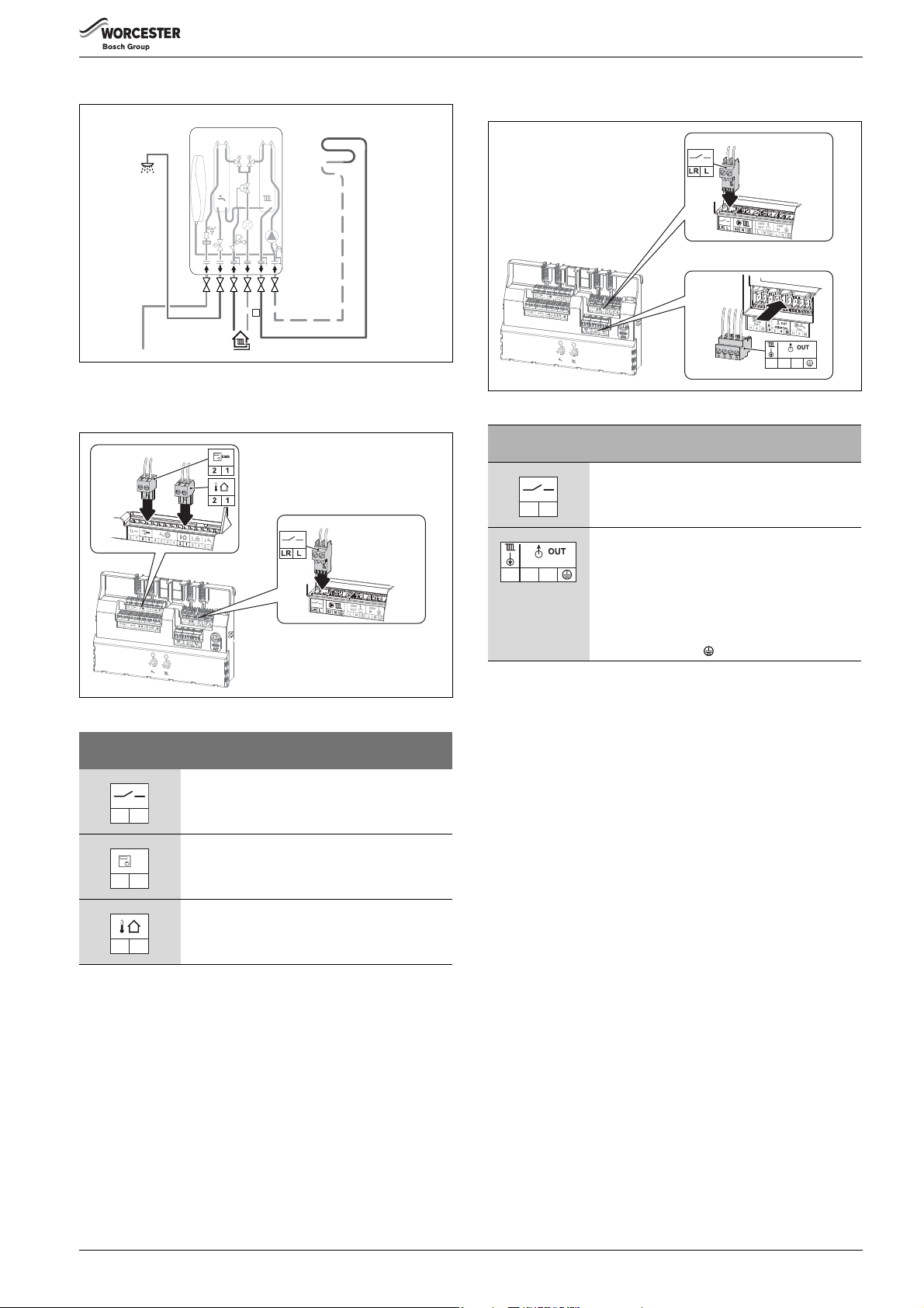
4.7.2 Unmixed central heating with under-floor
Fig. 16
Option 1: Control of under-floor with Sense II (EMS controller) example
Option 2: Control of under-floor with 230V programmable room thermostat example
Fig. 18
Connections/
Symbol
Function
Limiter thermostat (under-floor safety cut-off)
•Potential free
LR L
230 V feed to external time and temperature
control
• 230V programmable room thermostat
LR
120/230 VAC
N
L
– Switch live demand input [LR]
– Live output [L]
– Neutral output [N]
– Earth output [ ]
Fig. 17
Connections/
Symbol Function
Limiter thermostat (under-floor safety cut-off)
• Potential free
Sense II connection
EMS
21
• EMS2 Room control
– Not polarity sensitive
Outdoor temperature sensor
• Not polarity sensitive
6720808928-50.1Wo
6 720 808 928 (2017/06) 21
Loading...